Article

A Simplified Calculation Method of Seepage Flux for Slope-Wall Rock-Fill Dams with a Horizontal Blanket

1
State Key Laboratory of Hydrology-Water Resources and Hydraulic Engineering, Hohai University, Nanjing 210098, China
2
College of Water Conservancy and Hydropower Engineering, Hohai University, Nanjing 210098, China
*
Author to whom correspondence should be addressed.
Appl. Sci. 2020, 10(11), 3848; https://doi.org/10.3390/app10113848
Submission received: 1 May 2020 / Revised: 28 May 2020 / Accepted: 30 May 2020 / Published: 1 June 2020

Abstract

:
Seepage flux is very important in many hydraulic projects such as in the upper reservoir of a pumped storage power station because of its effect on economic benefits. However, upper reservoirs with a relatively high altitude are generally located above the groundwater level; thus, their leakage is difficult to estimate accurately. Here, using steady seepage theory and Darcy’s law, we propose a simplified calculation method to estimate the leakage of slope-wall rock-fill dams with a horizontal blanket. Using a one-dimensional governing equation for unsaturated seepage flows with the assumption of porous continuous media, formulas are derived for calculating the seepage flux of the dam in a steady state with different groundwater levels, which are mainly divided into two situations: those that are lower or higher than the bottom of the horizontal blanket. Then, two engineering examples are developed to assess the proposed method; the relative errors between the analytical results and numerical results are less than 10%. The results obtained from other analytical methods introduced by other researchers are also compared with our numerical results. The comparison results show that the proposed method is reliable and can be used for the estimation of reservoir leakage in situations where rapid results are needed, such as benefit assessments and safety evaluations.

1. Introduction

Rock-fill dams account for a large proportion of dams, due to their convenient supply of materials and few geological condition requirements. Considering the construction characteristics and operation mechanisms of rock-fill dams, their main failure modes can be divided into overtopping, slope stability, and seepage failures. Seepage failure is the main cause of rock-fill dam failure besides overtopping failures. Serious seepage failure not only affects the safe operation and economic benefits of reservoirs, but also threatens the safety of people’s lives and property in the downstream area. Therefore, it is of great significance to calculate and analyze the seepage of earth rock dams.
Theoretically speaking, the seepage calculation of a rock-fill dam involves solving a basic seepage equation with known definite conditions (initial conditions and boundary conditions) to obtain the seepage elements of dams, such as seepage flux, which is an important indicator for the state of dams during their operating period. Accordingly, many methods, such as numerical methods and analytical methods, have been employed to calculate the seepage flux of rock-fill dams.
Numerical methods can be used to calculate the leakage of rock-fill dams with homogeneous, heterogeneous, isotropic, anisotropic, or complex boundary conditions. At present, the most accurate numerical methods for seepage analysis include the finite element method [1,2,3,4], the finite difference method [5,6,7,8], and the boundary element method [9,10,11,12]. Hu and Li [13] numerically studied the seepage characteristics of a face rock-fill dam with different geomembrane defects and reservoir water levels, and the infiltration line was obtained. Molla [14] established a 2D finite element model of an embankment dam with an added vertical sheet pile, in order to study the effect of shapes and location of the sheet pile on the total seepage discharge and velocities. Calamak, et al. [15] investigated the steady-state seepage through a homogeneous and simple zoned earthen dam using the finite-element method, subsequently researched the characteristics of blanket, chimney, and toe drains. Based on the generalized equivalent continuum model, Chen, et al. [16] established a finite element model of a high face rock-fill dam under complex hydraulic conditions and then analyzed the seepage characteristics in the dam area, including the seepage flux, seepage gradient, etc. Additionally, many studies have combined random field concepts with finite element methods to perform Monte Carlo simulations of seepage problem [17,18,19,20,21,22,23].
Analytical methods are also employed to solve seepage problems based on Darcy’s law and some assumptions of rock-fill dams to ensure their simplification and intelligibility compared to numerical simulation. Slope-wall dams with horizontal blankets are usually divided into the following two sections during the derivation of seepage flux using an analytical method: One is leakage of the dam body—that is, seepage through the slope wall; the other is leakage of the dam foundation—that is, seepage through the horizontal blanket and the foundation below. Many studies on analytical methods for leakage calculation have been carried out by various researchers [24,25,26]. In the early stage of research, Bennett [27] pioneered a study of seepage flux through an equal thickness blanket, a curved blanket (approximate triangle), and a combination of natural and artificial blankets of slope-wall dams. After that, inspired by the segmentation method, Uginchus [28] divided a slope-wall dam into three sections to calculate the seepage flow, but the head loss at the inlet was not considered. Subsequently, the head loss at the inlet was taken into consideration, and a complete formula for an equal thickness blanket was developed under the conditions that the blanket length is greater than the foundation thickness [29]. Changxi [30] derived a calculation formula for the seepage flux of slope-wall dams based on the assumptions that the variation of head loss underneath the blanket is linear; the drag coefficient was determined by taking the average value of the seepage flux of the foundation, but this calculation formula cannot apply to longer or more permeable blankets. Besides, the U.S.B.R. [31] recommended an analytical method to estimate the seepage through dam foundation, considering the blanket to be impermeable; Casinader R and Rome G [32] approximated the shape of the concrete face as a triangle and derived a formula for calculating seepage through the dam body; Wang [33] computed the dam leakage mainly based on the subsection method and Darcy’ law. Furthermore, some scholars used the conformal transformation method to establish a mathematical model and derive a series of seepage calculation formulas for approximating the seepage flux of a rock-fill dam, though this method is complicated to apply in practice [34,35,36,37]. In addition, Yoshitake, et al. [38] demonstrated an analytical solution for a triangular blanket and a resultant solution for seepage discharge by introducing a modified Bessel function of the first orders, 0 and 1. Deng, et al. [39] proposed a simple calculation method to generalize the steady-state seepage of rock-fill dams with thin impervious elements, from which the seepage flux and apparent overall value of the permeability coefficient for impervious elements could be obtained.
However, the above studies mainly focus on dams with higher groundwater levels; little attention has been paid to dams located at a higher altitude and with a lower groundwater level. In addition, the existing methods for calculating leakage are relatively complicated to assess the benefits and evaluate the safety of dams. Thus, a more simplified calculation method of leakage is required.
In this study, based on Darcy’s law and the assumption of porous continuous media, a simplified calculation method is proposed to estimate the seepage flux of slope-wall rock-fill dams with a horizontal blanket in a steady state. The proposed method considers the influence of dams with different groundwater levels. Finally, two engineering examples are used to validate the proposed method by comparing the results of the proposed method with those of other analytical methods and a numerical method.

2. Methods

2.1. Assumption

In order to analyze the dam seepage effectively, several assumptions were made:
(1)
The groundwater level remains stable and the seepage process is in a steady state all the time.
(2)
The seepage behavior follows Darcy’s law.
(3)
Cracks in the horizontal blanket and slope wall are ignored.
(4)
Hysteresis in the soil–water characteristics is not considered.
(5)
The rock, soil, and water are not compressible, and the pore size and porosity of the soil remain unchanged during infiltration.
(6)
When there is water downstream, it is assumed that the seepage point, which is the intersection of the phreatic line and dam slope downstream, is flush with the downstream water level.
(7)
The horizontal blanket and slope wall are thin enough to assume that their hydraulic gradients along the seepage path remain constant.

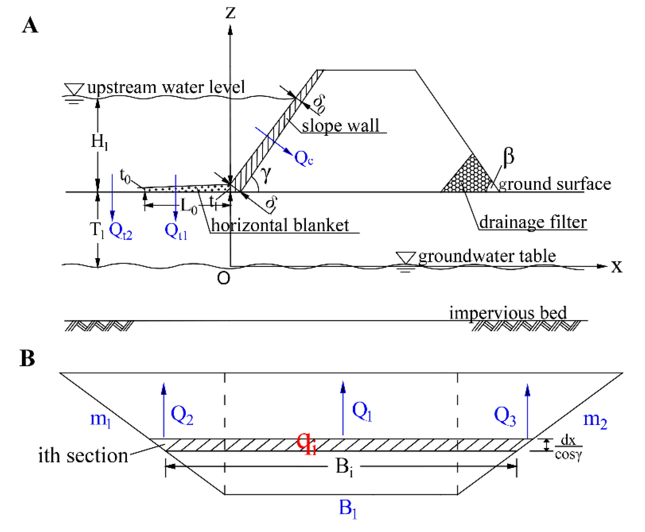
2.2. Mathematical Formulation

The simplified calculation method for estimating the seepage flux of slope-wall rock-fill dams is mainly divided into two situations: a groundwater level that is lower or higher than the bottom of the horizontal blanket.

2.2.1. Dams with a Low Groundwater Level

When the groundwater level is lower than the horizontal blanket, there is no direct hydraulic connection between the groundwater and reservoir water. Moreover, the permeability of the slope wall and horizontal blanket are usually much lower than those of the dam body and dam foundation. Under this situation, the slope wall and horizontal blanket are generally saturated, while the dam foundation under the horizontal blanket and the dam body behind the slope wall are unsaturated. Hence, it is assumed that the seepage directions are orthogonal to the slope wall and the horizontal blanket, as shown in Figure 1A. The total leakage of the dam is mainly divided into two parts for calculations: One is seepage through the slope wall; the other is seepage through the horizontal blanket.
The coordinate system for a typical cross-section of the dam is established in Figure 1A, with the groundwater level as the x-axis whose positive direction extends from upstream to downstream, where the z-axis is a positive direction from a low elevation to a higher elevation, and point O is the origin.
The symbols depicted in Figure 1A are defined as follows: the water level upstream is H 1 (above the ground surface), the thicknesses of the slope wall at height H 1 and the bottom are δ 0 and δ 1 , respectively, the thicknesses of the upstream and downstream end of the blanket are t 0 and t 1 , respectively, the blanket length is L 0 , the depth from the ground surface to the groundwater table is T 1 , and the angles of the dam slope upstream and downstream are γ and β , respectively.

Seepage through the Slope Wall

The slope wall is divided into n sections for calculation, which can be seen in Figure 1B. Based on Darcy’s law, leakage q i through the i t h section of the slope wall can be computed as:
q i = K A J = K c B i d x c o s γ · H 1 x t a n γ δ 1 ( δ 1 δ 0 ) t a n γ H 1 x
where K c and B i are the permeability coefficient and width of slope of the wall, respectively, and x denotes the horizontal distance between the ith section of the slope wall and point O.
Under three-dimensional conditions, the front view of the slope wall is simplified as shown in Figure 1B. The leakage through the middle part is Q 1 , and the leakage through both sides is Q 2 and Q 3 , respectively. The bottom width of the slope wall is B 1 , and the slope coefficients on both sides are m 1 and m 2 , respectively.
The total leakage Q c of the dam body can be calculated by integrating Equation (1) in the ( 0 , H 1 t a n γ ) interval:
Q c = Q 1 + Q 2 + Q 3 = K c B 1 H 1 ( δ 1 δ 0 ) s i n γ [ H 1 + δ 0 H 1 δ 1 δ 0 l n ( δ 1 δ 0 ) ] + ( m 1 + m 2 ) K c H 1 ( δ 1 δ 0 ) s i n 2 γ [ H 1 2 2 + δ 0 H 1 2 δ 1 δ 0 + δ 0 δ 1 H 1 2 ( δ 1 δ 0 ) 2 l n ( δ 1 δ 0 ) ] .
When the slope wall is of equal thickness δ , the total leakage Q c of the dam body can be rewritten as:
  Q c = K c B 1 H 1 2 2 δ s i n γ + ( m 1 + m 2 ) K c H 1 3 6 δ s i n 2 γ .

Seepage through the Horizontal Blanket

When the groundwater level is too low to affect the seepage field of the foundation below, and the permeability of the unsaturated area is lower than that of the saturated area of the foundation, it is assumed that the water flows vertically through blanket and foundation below. Leakage of the dam foundation includes leakage Q t 1 through the horizontal blanket and infiltration Q t 2 of the dam foundation through the riverbed surface at the front end of the blanket, as shown in Figure 1A.
(1) Leakage Q t 1 through the horizontal blanket
The blanket is divided into n calculation sections, so leakage q j of the j t h section can be expressed as:
q j = K A J = K t B t d x H 1 t 0 + L 0 + x L 0 ( t 1 t 0 ) ,
where K t is the permeability coefficient of the blanket, and B t denotes the width of the blanket leakage area.
Total leakage Q t 1 through the blanket can be calculated by integrating Equation (4) in the ( L , 0 ) interval:
Q t 1 = K t B t H 1 L 0 t 1 t 0 ln ( t 1 t 0 ) .
When the blanket is of equal thickness t , the total leakage Q t 1 through the blanket can be rewritten as
Q t 1 = K t B t H 1 L 0 t .
(2) Infiltration Q t 2 of the foundation through the riverbed surface at the front of the blanket
The Richards equation governing one-dimensional vertical flow in unsaturated soils can be written in the following form:
z [ K ( ψ ) ( ψ + z ) z ] = θ t ,
where K ( ψ ) is the unsaturated hydraulic conductivity, which is a function of the pressure head ψ (negative for unsaturated flow), θ is moisture content, t is the time, and z denotes the vertical coordinate pointing upwards.
Since this is a steady-state seepage process, Equation (7) can be simplified as:
z [ K ( ψ ) ( ψ + z ) z ] = 0 .
To linearize Equation (8), the soil water characteristic curve and hydraulic conductivity function of unsaturated soil are described by the Gardner–Russo model as follows [40]:
K ( ψ ) = K s e α ψ
θ ( ψ ) = θ r + ( θ s θ r ) e α ψ ,
where K s is the saturated hydraulic conductivity, α is the soil parameter related to the pore size distribution, θ r is residual moisture content, and θ s denotes the saturated moisture content.
Using the two constitutive relations above, Equation (8) can be transformed into the following linearized governing equation:
z [ K s e α ψ ( ψ z + 1 ) ] = 0 .
A particular solution to Equation (10) requires two boundary conditions:
  • At the steady ground water table, ψ 0 = 0 , the boundary condition can be written as
    K ( ψ 0 ) | z = 0 = K s .
  • The surface boundary is controlled by pore water pressure (which is the upstream water level H 1 constantly):
    K ( ψ s ) | z = T 1 = K s e α H 1 .
The solution for Equation (10) with the boundary conditions of Equation (11) and Equation (12) is:
ψ = 1 α ln ( e α H 1 1 1 e T 1 e α z + 1 e α H 1 T 1 1 e T 1 ) .
By substituting Equation (13) into Equation (9b), the total amount of soil infiltration Q t 2 can be calculated as:
Q t 2 = A s 0 T 1 ( θ ( ψ ) θ 0 ) d z       = A s { [ θ r θ 0 + ( θ s θ r ) 1 e α H 1 T 1 1 e T 1 ] T 1 e α H 1 1 α ( 1 e T 1 ) ( e α T 1 1 ) } ,
where θ 0 is the initial moisture content, and A s is the leakage area of the dam foundation at the front of blanket.
Consequently, the total leakage Q t o t a l can be obtained by adding Equation (3), Equation (6), and Equation (14):
Q t o t a l = Q c + Q t 1 + Q t 2 .

2.2.2. Dams with a High Groundwater Level

When the groundwater level is at/or higher than the horizontal blanket, the dam foundation and dam body below the phreatic line are in a saturated state.
The coordinate system and head distribution for a typical cross-section of the dam is established in Figure 2A, with the impervious bed as the x-axis positive to the right and the z-axis in the positive direction from low to high elevation, with point O as the origin.
The symbols are also depicted in Figure 2A and defined as follows: The water level downstream is H 2 above the ground surface, the thicknesses of the slope wall and blanket are δ and t , respectively, the depth of the permeable foundation is T, the horizontal distance from the bottom of the slope wall to the beginning of the filter is L 1 , the head losses at the upstream and downstream ends of the blanket are Δ h 0 and Δ h 1 , respectively, and the water level behind the slope wall is h 1 . The other symbols are the same as those described in Section 2.2.1.
Considering the seepage of the layered soil, the equivalent permeability coefficients of the foundation are [41]:
K y ¯ = i = 1 n l i i = 1 n l i K i
K x ¯ = i = 1 n l i K i i = 1 n l i
where l i is the thickness of the i t h layer, and K i is the permeability coefficient of the i - t h layer.
The seepage flux of the slope-wall rock-fill dam with a horizontal blanket is calculated by the subsection method, taking the slope wall and blanket (including the foundation under the blanket) as section I and the dam body behind slope wall and the foundation under the dam body as section II, which can be seen in Figure 2A.

Seepage Flux q 1 Per Unit Width through Section I

(1)
Seepage flux q i per unit width of the foundation passing through the vertical section at the end of the blanket
If the ratio of the foundation permeability coefficient K x ¯ to blanket K t is greater than 10, it is assumed that the water flow is vertical through the horizontal blanket and horizontal through the dam foundation [27].
Seepage flux through the blanket with d x -length is written as:
d q t = K t Δ h t d x .
The increment of the d x -length foundation seepage flux is
d q = K x ¯ T d 2 ( Δ h ) d x 2 d x .
The seepage differential equation for the blanket can be obtained as follows by equating Equation (17) with Equation (18):
d 2 ( Δ h ) d x 2 = a 1 2 Δ h ,
where a 1 = K t K x ¯ T t .
The boundary conditions are expressed as:
{ Δ h = Δ h 0               x = L 0 Δ h = Δ h 1                   x = 0 .
The general solution of Equation (19) subjected to the boundary conditions given by Equation (20) is:
Δ h = 1 s h ( a 1 L 0 ) { Δ h 1 s h [ a 1 ( L 0 + x ) ] Δ h 0 s h ( a 1 x ) } .  
The seepage gradient of the foundation can be written as:
J = a 1 s h ( a 1 L 0 ) { Δ h 1 c h [ a 1 ( L 0 + x ) ] Δ h 0 c h ( a 1 x ) } .
Therefore, the seepage flux at the front end of the blanket can be deduced:
q 0 = K x ¯ T J x = L 0 = a 1 K x ¯ T s h ( a 1 L 0 ) [ Δ h 1 Δ h 0 c h ( a 1 L 0 ) ] ,
which can also be written as:
q 0 = K x ¯ Δ h 0 ζ ,
where ζ = 0.44 .
Δ h 0 can be obtained by equating Equation (23) with Equation (24):
Δ h 0 = a 1 ζ T Δ h 1 a 1 ζ T c h ( a 1 L 0 ) + s h ( a 1 L 0 ) .
The seepage gradient of the foundation at x = 0 is calculated as:
J x = 0 = a 1 Δ h 1 a 1 ζ T t h ( a 1 L 0 ) + 1 a 1 ζ T + t h ( a 1 L 0 ) .
The equivalent length of the blanket can be expressed as:
L e = Δ h 1 J x = 0 = a 1 ζ T + t h ( a 1 L 0 ) a 1 + a 1 2 ζ T t h ( a 1 L 0 ) .
Δ h 1 can also be approximately given as:
Δ h 1 = H 1 [ 1 + H 1 H 2 ( L e + L ) t a n γ ] h 1 ,
where L = L 1 + 0.44 T .
Consequently, the seepage flux per unit width q 1 of the foundation passing through the vertical section at the end of the blanket is derived as:
q 1 = K x ¯ T J x = 0 = i = 1 n l i K i a 1 { H 1 [ 1 + H 1 H 2 ( L e + L ) t a n γ ] h 1 } a 1 ζ T t h ( a 1 L 0 ) + 1 a 1 ζ T + t h ( a 1 L 0 ) .
(2)
The seepage flux q c per unit width through the slope wall
Assuming that the head loss of the slope wall is linear, the seepage flux q 1 through the i t h section of the slope wall can be computed as:
q i = { K c d x c o s γ Δ h 1 + H 1 Δ h 1 h 1 h 1 x t a n γ δ         ( 0 < x h 1 t a n γ ) K c d x c o s γ H 1 x t a n γ δ                                 ( h 1 t a n γ < x H 1 t a n γ ) .
The total seepage flux of the slope wall per unit width can be calculated by integrating and combining Equation (30):
q c = K c 2 δ s i n γ [ ( Δ h 1 H 1 ) h 1 + H 1 2 ] .
Under three-dimensional conditions, the front view of the slope wall is simplified as shown in Figure 2B. The total seepage flux Q c of the slope wall is written as:
Q c = K c B 1 2 δ s i n γ [ H 1 2 H 1 h 1 + h 1 Δ h 1 ] + K c ( m 1 + m 2 ) 6 δ s i n 2 γ [ h 1 2 Δ h 1 H 1 h 1 2 + H 1 3 ] .
(3)
The seepage flux q 2 per unit width through Section II is calculated as:
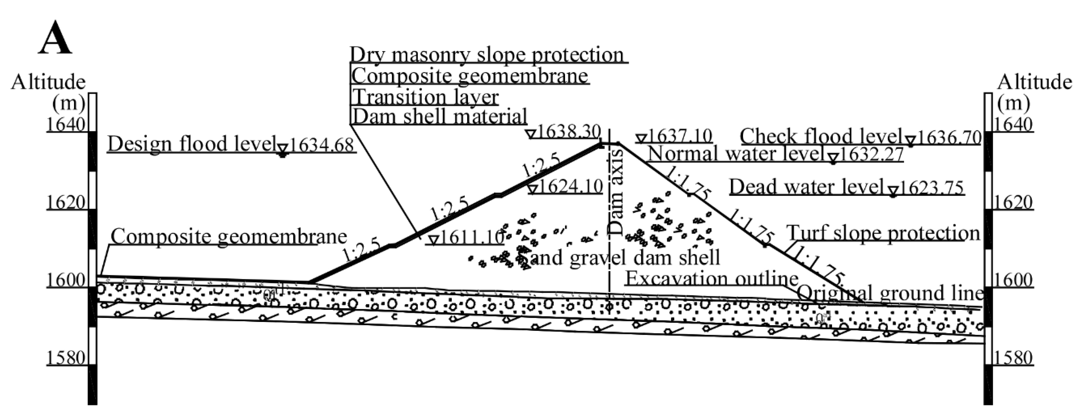
q 2 = K b ( h 1 2 H 2 2 ) 2 L 1 + K x ¯ ( h 1 H 2 ) T L 1 + 0.44 T ,
where K b denotes the permeability coefficient of the dam body.
Since the seepage flux through Section I is equal to that through Section II, the continuity condition at the interface is written as:
q 2 = q c + q 1 .
h 1 can be derived by trial calculations of Equation (34); then, the total seepage flux Q t o t a l can be obtained by substituting h 1 into Equation (35):
Q t o t a l = q 1 B t + Q c ,
where B t is the width of the horizontal blanket.

3. Case Studies

Corresponding to the above two situations, the leakage of two engineering examples is calculated. The numerical results of the two engineering examples are also obtained to verify the proposed method.

3.1. Dams with a Low Groundwater Level

The Fukang pumped storage power station under construction is located in Fukang City, Xinjiang, China. Its lower reservoir is located in the main stream of Baiyang River, with one main dam and one embankment dam for sediment storage, forming an independent lower reservoir between the main dam and the embankment dam. The embankment dam is a composite geomembrane slope-wall rock-fill dam, with a crest elevation of 1815 m, a crest width of 8 m, and upstream and downstream comprehensive slope ratios of about 1:3 and 1:2, respectively. The ground surface elevation of the dam is 1795.8 m. As an anti-seepage material, the slope wall and blanket adopt a compound geomembrane made of two fabrics with a membrane. (500 g/1 mm/500 g).
Two calculation conditions according to the dam design information provided by the Design Institute [42,43] are listed as follows. The design flood level is 1807.43 m, and the corresponding water level downstream is 1775 m; the check flood level is 1812.5 m, and the corresponding water level downstream is 1775 m. A typical cross section and dam axis section of the embankment dam are shown in Figure 3, and the permeability coefficients of the materials are listed in Table 1.

3.1.1. Numerical Simulation

Here, according to the topographic conditions and geological survey data of the Fukang pumped storage power station, the finite element mesh model is established to calculate the seepage field of the reservoir using the finite element method. A model of the whole dam, with 102,332 superelements and 108,074 nodes in total, is shown in Figure 4a. The size of the whole dam model is 700 m along the water flow direction and 860 m in the other horizontal direction.
After the three-dimensional finite element calculations, considering steady seepage under two calculation conditions (the design flood level and check flood level conditions), the potential distributions of the seepage field and seepage flux during the operational period are obtained as shown in Figure 5 and Table 2. Figure 5 reveals that the saturation surface is almost coincident with the groundwater line, which is lower than the horizontal blanket, and a section of unsaturated soil is formed between the river surface and groundwater line.

3.1.2. Proposed Calculation Method

According to the engineering design information, the values of the variables needed for calculations are depicted in Figure 6.
We conclude the following:
t = 1   mm ,   δ = 1   mm ,   γ = 16.29 ,   m 1 = 0.82 ,   m 2 = 0.52 ,   L 0 = 142.54   m , B t = 205.26   m
H 1 = u p s t r e a m   w a t e r   l e v e l 1795.8   m .
By substituting the above values into Equation (15), the seepage flux of the Fukang slope-wall rock-fill dam can be calculated as shown in Table 2.

3.1.3. Comparison between the Calculation Results

In order to calculate the seepage through dams with a low groundwater level, a limited number of analytical methods were introduced by several scholars. The USBR code [31] recommends the following method to estimate seepage through the dam foundation:
Q t = K x ¯ B T H 1 L 0 + δ + 0.43 T .
Casinader R and Rome G [32] approximated the profile of the concrete face as a triangle and derived a formula for calculating seepage through the dam body as follows:
Q c = K c L c H 1 2 6 δ s i n γ ,
where L c is the crest length.
Fu et al. [44] proposed a simple method for dam body leakage calculations as follows:
Q c = 1 n K c H n 2 2 δ s i n γ L n .
where L n is the length of the panel, and H n is the maximum head of the panel.
Gang et al. [39] also proposed a leakage calculation method for the dam body, which can be applied to different shapes of the slope wall. The formula is presented as:
Q c = l l o w e s t l H 1 K c H ( l ) δ W X ( l ) d l
H ( l ) = { H 1 z       z > H 2   H 1 H 2       z < H 2 .    
To evaluate the application of the proposed method for engineering applications, the relative error (RE) and root mean squared error (RMSE) are introduced as:
RE = O i S i S i × 100 %
RMSE = 1 n i = 1 n ( O i S i ) 2 ,
where n is the number of data, and O i and S i are the analytical results and numerical results under different calculation conditions.
Comparisons between these analytical results (using the above methods to calculate the seepage flux of the Fukang pumped storage power station) and the numerical results are shown in Table 2.
It can be observed from Table 2 that the analytical results obtained by the proposed method are slightly larger than the numerical results, but their relative errors are less than 5%, which is acceptable. Small discrepancies may be caused by simplification of the slope wall and horizontal blanket and the assumptions of the vertical downward seepage direction in the proposed method. In contrast, the numerical method can simulate a more complicated and realistic seepage path.
In addition, compared to the proposed method, the USBR method is relatively unreliable due to to its large RMSE and RE, as this method considers the blanket to be impermeable and the seepage direction of the dam foundation to be horizontal when the groundwater is low, which does not accord with reality. The results of the Deng Gang method provide as good an estimation as the proposed method. Nevertheless, there are few distinctions between these methods, since the shape of the slope wall is simplified in the proposed method. The results obtained using Casinader method differ significantly with the numerical results, as the Casinader method approximates the shape of the slope wall as a triangle, which means that the area of maximum water head only appears at the vertex of the triangle in the seepage calculations. The Chunjiang Fu method also suffers from instability, since this method regards the water head of each point on the slope wall as the maximum head. Thus, when there is a low water level, the seepage calculations are comparatively accurate. As the water level rises, the maximum water head and the errors also become larger.
To conclude, the above analysis indicates that the proposed simplified calculation method is reasonably accurate and is reliable for engineering applications.

3.2. Dams with High Groundwater Level

The Shangmo reservoir which is a small-scale project mainly for urban water supply and flood control, is located on the Jinjiahe River to the west of Tianshui city. The dam of the Shangmo reservoir is a composite geomembrane slope-wall rock-fill dam with a crest width of 6 m, a crest length of 202.8 m, and a crest elevation of 1637.1 m. The ground surface elevation of the dam is 1600 m, and the upstream and downstream comprehensive slope ratios are about 1:2.5 and 1:1.75, respectively. A composite geomembrane two fabrics with a membrane (250 g/1 mm/250 g) is laid on the dam slope upstream of the dam body and riverbed surface.
According to the dam design information provided by the Design Institute [45,46], two calculation conditions are listed. The normal water level is 1632.21 m, and the corresponding water level downstream is 1603.19 m; the designed flood level is 1634.68 m, and the corresponding water level downstream is 1603.19 m.
Typical cross section and dam axis sections of the Shangmo dam are shown in Figure 7, and the permeability coefficients of the materials are listed in Table 3.

3.2.1. Numerical Simulation

Here, according to the topographic conditions and geological survey data of the Shangmo reservoir, two models are established to calculate the seepage field of the reservoir using the finite element method. The finite element mesh model of the whole dam, with 81,352 superelements and 886,688 nodes in total, is shown in Figure 8a. The size of the whole dam model is 2000 m along the water flow direction and 800 m in the other horizontal direction.
After the three-dimensional finite element calculations, considering steady seepage under two calculation conditions (a normal level and the designed flood level conditions), the potential distribution of the seepage field and seepage flux during the operational period are obtained as shown in Figure 9 and Table 4. Figure 9 reveals that the dam foundation and dam body below the phreatic line are in a saturated state.

3.2.2. Proposed Calculation Method

The values of the variables needed according to the engineering design information are provided in Figure 10. We can conclude that:
K x ¯ = 5.64 × 10 6   m · s 1 , T = 149.07   m ,   L 0 = 1687   m ,   L 1 = 200 H 2 t a n β ,   t = 1   mm , δ = 1   mm ; γ = 25.52 ° ,   β = 33.12 ° ,   B 1 = 141.60   m ,   m 1 = 0.43 ,   m 2 = 0.25 ; H 2 = d o w n s t r e a m   w a t e r   l e v e l 1600   m ,   H 1 = u p s t r e a m   w a t e r   l e v e l 1600   m .
By substituting the above values of variables into Equation (35), the seepage flux of the Shangmo slope-wall rock-fill dam can be calculated as shown in Table 4.

3.2.3. Comparison between the Calculation Results

In order to calculate the seepage through dams with a high groundwater level, several analytical methods were introduced by several scholars, as shown below.
Аравин В.И. and Нумерoв С.Н. [47] proposed a method to estimate the seepage per width through a dam as follows:
q c = K c ( 1 + c o t 2 γ ) ( H 1 2 H 2 2 ) 2 δ
q t = K x ¯ α ( H 1 H 2 ) ( T t ) t h ( α L 0 ) , α = K t K x ¯ t ( T t ) .
Wang [33] computed dam leakage based on the subsection method:
q c = K c ( H 1 2 h 1 2 ) 2 δ s i n γ
q t = K x ¯ K t T t c t h ( A L 0 ) ( H 1 h 1 ) , A = K t K x ¯ T t
q 2 = K b ( h 1 2 H 2 2 ) 2 L 1 + K x ¯ ( h 1 H 2 ) T L + 0.44 T .
Table 4 shows the comparison results obtained from our proposed method, Аравин В.И. and Нумерoв С.Н.’s method, Wang’s method, Gang’s method, and the numerical method. Table 4 shows that the analytical results obtained from the proposed method are slightly different from those of the numerical results, but their relative errors are less than 5%, which is acceptable.
The small differences between these models are due to the following reasons: (1) the dam foundation and the shapes of the slope wall and blanket are simplified in the proposed method, while those simulated by the numerical method are more precise and closer to reality; (2) the water flow direction in the proposed method is also simplified compared to the numerical simulation; (3) the pore water pressure might become negative in the area of the slope wall that is higher than the reservoir water level, and its distribution will be more complex as well, which is difficult to achieve using an analytical method.
In addition, compared to the proposed method, Аравин В.И. and Нумерoв С.Н.’s method is a conservative seepage calculation approach, whose results are clearly different from those of the numerical results because Аравин В.И. and Нумерoв С.Н.’s method does not consider the head loss of the dam body and a relatively large hydraulic gradient may be concentrated in the slope wall, which may lead to large errors and uneconomical designs. Wang’s method performs well for seepage calculations of the dam body but poorly in seepage calculations of the dam foundation, as it ignores seepage through areas higher than the water level behind the slope wall. Gang’s method provide a good estimation of dam body seepage that can suit any slope wall shape, but the formula does not account for head loss of the dam body.
The results indicate that the proposed method provides a good estimation compared to the numerical method and some other analytical methods introduced by scholars. The proposed method offers high precision under high groundwater level conditions and can be applied to engineering analyses.

4. Conclusions

This study proposed a simplified calculation method for estimating the leakage of a slope-wall rock-fill dam with a horizontal blanket in a steady state, mainly based on Darcy’s law and the assumption of porous continuous media. The proposed method is available for dams with different water levels. Moreover, the shapes of the slope wall and blanket, dam height, and dam slope ratios are considered in the proposed method.
Subsequently, two engineering examples in this study are used to investigate the accuracy of the proposed method. The results obtained from the proposed method are in agreement with those of the numerical method, and the relative errors between them are less than 5%, which is acceptable. This result illustrates that the proposed method is capable of dam seepage estimation and can be used in initial dam designs. The analytical methods introduced by other researchers were also compared with the numerical results. Some of these methods are comparatively unreliable, as there are considerable discrepancies between their results and the numerical results, which may lead to uneconomical designs.
Ultimately, the proposed method can estimate and predict the seepage flux of embankment dams with adequate accuracy and rapidity and could be applied to practical engineering. On the one hand, seepage estimation using the proposed method could be employed to demonstrate the performance of seepage prevention measures for dams in the initial stages of dam design and is more convenient than the numerical simulations used in the past. On the other hand, estimations can be used approximately for safety evaluations and benefit assessments to avoid uneconomical dam designs during the initial feasibility research into dam construction.

Author Contributions

Conceptualization, G.L. and Z.S.; formal analysis, G.L.; funding acquisition, Z.S.; validation G.L.; writing—original draft, G.L.; writing—review and editing, Z.S. and C.Y. All authors have read and agreed to the published version of the manuscript.

Funding

This work was funded by the Project of the National Natural Science Foundation of China/Yalong River Joint Fund [U1765205], the Priority Academic Program Development of Jiangsu Higher Education Institutions [YS11001], and the Fundamental Research Funds for the Central Universities [20188630X14].

Conflicts of Interest

The authors declare no conflict of interest.

References

  1. Li, M.-C.; Guo, X.-Y.; Shi, J.; Zhu, Z.-B. Seepage and stress analysis of anti-seepage structures constructed with different concrete materials in an RCC gravity dam. Water Sci. Eng. 2015, 8, 326–334. [Google Scholar] [CrossRef] [Green Version]
  2. Pedroso, D.M. A solution to transient seepage in unsaturated porous media. Comput. Methods Appl. Mech. Eng. 2015, 285, 791–816. [Google Scholar] [CrossRef] [Green Version]
  3. Fu, J.F.; Sheng, J.I.N. A study on unsteady seepage flow through dam. J. Hydrodyn. 2009, 4, 499–504. [Google Scholar] [CrossRef]
  4. Athani, S.S.; Solanki, C.; Dodagoudar, G. Seepage and stability analyses of earth dam using finite element method. Aquat. Procedia 2015, 4, 876–883. [Google Scholar] [CrossRef]
  5. Fukuchi, T. Numerical analyses of steady-state seepage problems using the interpolation finite difference method. Soils Found. 2016, 56, 608–626. [Google Scholar] [CrossRef]
  6. Lee, S.S.; Yamashita, T. Finite-Difference Method Three-Dimensional Model for Seepage Analysis Through Fordyce DAM. In Advances in Geosciences: Volume 6: Hydrological Science (HS); World Scientific: Singapore, 2007; pp. 171–180. [Google Scholar] [CrossRef]
  7. Rohaninejad, M.; Zarghami, M. Combining Monte Carlo and finite difference methods for effective simulation of dam behavior. Adv. Eng. Softw. 2012, 45, 197–202. [Google Scholar] [CrossRef]
  8. Hansen, D.; Roshanfekr, A. Assessment of potential for seepage-induced unraveling failure of flow-through rockfill dams. Int. J. Geomech. 2012, 12, 560–573. [Google Scholar] [CrossRef]
  9. Chang, C.S. Boundary element method in drawdown seepage analysis for earth dams. J. Comput. Civ. Eng. 1987, 1, 83–98. [Google Scholar] [CrossRef]
  10. Sánchez-Sesma, F.J.; Arellano-Guzmán, M.; Pérez-Gavilán, J.J.; Suarez, M.; Marengo-Mogollón, H.; Chaillat, S.; Jaramillo, J.D.; Gómez, J.; Iturrarán-Viveros, U.; Rodríguez-Castellanos, A. Seismic response of three-dimensional rockfill dams using the Indirect Boundary Element Method. In Proceedings of IOP Conference Series: Materials Science and Engineering; IOPscience: London, UK, 2010; p. 012167. [Google Scholar]
  11. Abou-Seeda, H.M. Nonlinear Seismic Response of Dams Using a Coupled Boundary Element-Finite Element Formulation; Rice University: Houston, TX, USA, 1996. [Google Scholar]
  12. Kai, C.; De-gao, Z.; Xian-jing, K.; Jing-mao, L. Novel nonlinear polygon scaled boundary finite element method and its application. J. Zhejiang Univ. (Eng. Sci.) 2017, 51, 1996–2004. [Google Scholar] [CrossRef]
  13. Hu, J.; Li, C. Numerical simulation of seepage stability of slab dam with sudden drop of reservoir water level based on face plate defect. Chin. J. Geol. Hazard Control 2019, 30, 129–136. [Google Scholar]
  14. Molla, D.A.E. Seepage through homogeneous earth dams provided with a vertical sheet pile and formed on impervious foundation. Ain Shams Eng. J. 2019, 10. [Google Scholar] [CrossRef]
  15. Calamak, M.; Yilmaz, A.N.; Yanmaz, A.M. Performance Evaluation of Internal Drains of Earthen Dams. J. Perform. Constr. Facil. 2018, 32, 10. [Google Scholar] [CrossRef]
  16. Chen, S.; He, Q.; Cao, J. Seepage simulation of high concrete-faced rockfill dams based on generalized equivalent continuum model. Water Sci. Eng. 2018, 11, 250–257. [Google Scholar] [CrossRef]
  17. Fenton, G.A.; Griffiths, D. Statistics of block conductivity through a simple bounded stochastic medium. Water Resour. Res. 1993, 29, 1825–1830. [Google Scholar] [CrossRef] [Green Version]
  18. Griffiths, D.; Fenton, G.A. Seepage beneath water retaining structures founded on spatially random soil. Geotechnique 1993, 43, 577–587. [Google Scholar] [CrossRef] [Green Version]
  19. Fenton, G.A.; Griffiths, D. Statistics of free surface flow through stochastic earth dam. J. Geotech. Eng. 1996, 122, 427–436. [Google Scholar] [CrossRef]
  20. Fenton, G.A.; Griffiths, D. Extreme hydraulic gradient statistics in stochastic earth dam. J. Geotech. Geoenviron. Eng. 1997, 123, 995–1000. [Google Scholar] [CrossRef] [Green Version]
  21. Gui, S.; Zhang, R.; Turner, J.P.; Xue, X. Probabilistic slope stability analysis with stochastic soil hydraulic conductivity. J. Geotech. Geoenviron. Eng. 2000, 126, 1–9. [Google Scholar] [CrossRef]
  22. Srivastava, A.; Babu, G.S.; Haldar, S. Influence of spatial variability of permeability property on steady state seepage flow and slope stability analysis. Eng. Geol. 2010, 110, 93–101. [Google Scholar] [CrossRef]
  23. Cho, S.E. Probabilistic analysis of seepage that considers the spatial variability of permeability for an embankment on soil foundation. Eng. Geol. 2012, 133, 30–39. [Google Scholar] [CrossRef]
  24. Chahar, B.R. Determination of length of a horizontal drain in homogeneous earth dams. J. Irrig. Drain. Eng. 2004, 130, 530–536. [Google Scholar] [CrossRef]
  25. Abdul Hussain, I.A.; Kashyap, D.; Hari Prasad, K. Seepage modeling assisted optimal design of a homogeneous earth dam: Procedure evolution. J. Irrig. Drain. Eng. 2007, 133, 116–130. [Google Scholar] [CrossRef]
  26. Fakhari, A.; Ghanbari, A. Note: A simple method for calculating the seepage from earth dams with clay core. J. Geoengin. 2013, 8, 27–32. [Google Scholar] [CrossRef]
  27. Bennett, P.T. The effect of blankets on seepage through pervious foundation. Trans. ASCE 1945, 111, 215–228. [Google Scholar]
  28. Uginchus, A. Seepage through Earth Dams.(Raschet Filtratsii Cherez Zemlyanye Plotiny); Israel Program for Scientific Translations: Jerusalem, Israel, 1966. [Google Scholar]
  29. Chugayev, P.P. Subsurface Loops in Hydraulic Engineering Structures: Design of the Subsurface Portion of the Dam on a Non-Rock Foundation (in Russian); Energy: Saint Petersburg, Russia, 1974. [Google Scholar]
  30. Changxi, M. Computation of seepage through earth dams with upstream blanket and sloping core (in Chinese). J. Hydraul. Eng. 1963, 1, 26–43. [Google Scholar] [CrossRef]
  31. U.S.B.R. Embankment Dams. In Chapter 5 Seepage Analysis; U.S. Department of the Interior, Bureau of Reclamation: Washington, DC, USA, 1987. [Google Scholar]
  32. Casinader, R.; Rome, G. Estimation of leakage through upstream concrete facings of rockfill dams. In Proceedings of the 16th International Congress on Large Dams, San Francisco, CA, USA, 13–17 June 1988. [Google Scholar]
  33. Wang, S. Theories and Methods of Hydraulic Design; China Water & Power Press: Beijing, China, 2000. [Google Scholar]
  34. Rezk, M.A.E.-R.M.; Senoon, A.E.-A.A.A. Analytical solution of seepage through earth dam with an internal core. Alex. Eng. J. 2011, 50, 111–115. [Google Scholar] [CrossRef] [Green Version]
  35. Kacimov, A.; Al-Maktoumi, A.; Obnosov, Y.V. Seepage through earth dam with clay core and toe drain: The Casagrande–Numerov analytical legacy revisited. ISH J. Hydraul. Eng. 2019. [Google Scholar] [CrossRef]
  36. Haitao, M. Study on Seepage Control Calculation Method and Anti-Seepage Measures of Earth-Rock Dam on the Infinite Deep Pervious Foundation (in Chinese); Xinjiang Agricultural University: Urumchi, China, 2010. [Google Scholar]
  37. Baozhong, Z. Seepage calculation of earth dam with impervious blanket and inclined wall on infinite deep permeable foundation (in Chinese). J. Hydraul. Eng. 1981, 5, 61–68. [Google Scholar] [CrossRef]
  38. Yoshitake, Y.; Kobayashi, N.; Fujihara, M.; Nishiyama, T. An analytical solution of seepage discharge from a reservoir of embankment dam with triangular soil blanket and its applicability. Trans. Jpn. Soc. Irrig. Drain. Rural Eng. 2011, 79, 109–115. [Google Scholar] [CrossRef]
  39. Deng, G.; Cao, K.; Chen, R.; Zhang, X.; Yin, Q.; Zhou, H. A simple approach to evaluating leakage through thin impervious element of high embankment dams. Environ. Earth Sci. 2018, 77, 25. [Google Scholar] [CrossRef]
  40. Gardner, W. Some steady-state solutions of the unsaturated moisture flow equation with application to evaporation from a water table. Soil Sci. 1958, 85, 228–232. [Google Scholar] [CrossRef]
  41. Polubarinova-Koch, P.I. Theory of Ground Water Movement; Princeton University Press: Princeton, NJ, USA, 1962. [Google Scholar]
  42. Cui, B.; Kong, D.; Jia, W.; Yu, S. General layout and building design of Fukang Pumped Storage Power Station (in Chinese). In Proceedings of the China Society for Hydropower Engineering, Beijing, China, 19–21 May 2015; 2015; pp. 130–135. [Google Scholar]
  43. Ouyang, M.; Mu, Z. Analysis on Flood Impact Assessment of Fukang Pumped Storage Power Station Project. China Water Power Electrif. 2018, 33–37. [Google Scholar] [CrossRef]
  44. Fu, C.; Li, J.; Wang, Y. Research on seepage monitoring indicators for the reservoir basin of pumped storage power station. Dam Safe. 2011, 12–14, 18. [Google Scholar]
  45. Su, J. Study on the risk mitigation and reinforcement scheme for the flood cavern of the Shangmao water source project (in Chinese). Gansu Water Resource. Hydropower Technol. 2011, 47, 8–9, 20. [Google Scholar]
  46. Wang, Y. Shangma water source project of Tianshui city (in Chinese). Water Wastewater Eng. 2011, 49, 117. [Google Scholar] [CrossRef]
  47. Аравин, В.И.; Нумерoв, С.Н. Seepage Calculation of Hydraulic Structure (in Russian); USSR National Architectural Engineering and Architectural Art: Saint Petersburg, Russia, 1955. [Google Scholar]
Figure 1. Layouts generalization of the slope-wall dam with a horizontal blanket (low groundwater level): (A) a typical cross section of the dam; (B) front view of the simplified slope wall.
Applsci 10 03848 g001
Figure 2. Layout generalization of the slope-wall dam with a horizontal blanket (high groundwater level): (A) a typical cross section of the dam; (B) front view of the simplified slope wall.
Applsci 10 03848 g002
Figure 3. Sections of the embankment dam for sediment storage: (A) a typical cross section; (B) the dam axis section.
Applsci 10 03848 g003
Figure 4. Finite element mesh models. (a) The whole dam. (b) The compound geomembrane.
Applsci 10 03848 g004
Figure 5. Potential distributions of the seepage field at a typical cross-section of the dam body: (a) in the designed flood level condition; (b) in the check flood level condition.
Applsci 10 03848 g005
Figure 6. Simplified calculation diagrams: (A) a typical cross section of the embankment dam; (B) front view of the simplified slope wall.
Applsci 10 03848 g006
Figure 7. Sections of the Shangmo dam: (A) a typical cross section; (B) the dam axis section.
Applsci 10 03848 g007aApplsci 10 03848 g007b
Figure 8. Finite element mesh models: (a) the whole dam; (b) the compound geomembrane.
Applsci 10 03848 g008
Figure 9. Potential distributions of the seepage field at a typical cross-section of the dam body: (a) in normal water level conditions; (b) in the designed flood level conditions.
Applsci 10 03848 g009
Figure 10. Simplified calculation diagrams: (A) a typical cross section of the Shangmo dam; (B) a front view of the simplified slope wall.
Applsci 10 03848 g010
Table 1. Permeability coefficients of the materials in each area.
PositionMaterial PartitionPermeability Coefficient (cm/s)
Foundationsand gravel (upper)4.00 × 10⁻³
sand gravel (lower)1.50 × 10⁻²
strong weathered rock1.00 × 10−4
week weathered rock1.00 × 10−5
overburden1.35 × 10−2
DamComposite geomembrane1.00 × 10−8
Main rock-fill (dam body)1.00 × 10⁻¹
cushion material5.00 × 10−2
berm1.35 × 10−2
Table 2. Comparison of the calculated results between the calculation method and the numerical simulation for the Fukang composite geomembrane slope-wall rock-fill dam.
PositionsMethodsDesign Flood LevelCheck Flood LevelRMSE
Leakage
(m3·d−1)
RE (%)Leakage
(m3·d−1)
RE (%)
Blanket Q t Proposed
method
2716.464.203896.644.36138.73
USBR
method
3173.7121.74021.827.71449.51
Numerical
method
2606.97/3733.84//
Slope wall Q c Proposed
method
364.174.79777.594.9128.30
Casinader
method
208.4740.0755.501.9398.84
Chunjiang Fu
method
304.4912.381275.0772.02378.73
Deng Gang
method
359.933.57761.832.7817.02
Numerical
method
347.52/741.20//
Total Q t o t a l Proposed
method
3080.637.924674.236.84265.19
Numerical
method
2854.49/4375.04//
Table 3. Permeability coefficient of the materials in each area.
PositionMaterial PartitionPermeability Coefficient (cm/s)
FoundationStrong permeable layer
100Lu ≤ q
2.0 × 10⁻³
Medium permeable layer
10Lu ≤ q < 100Lu
3.0 × 10⁻⁴
Weak permeable layer
5Lu ≤ q < 10Lu
5.0 × 10⁻⁵
Relative impermeable layer
q < 5Lu
2.0 × 10⁻⁵
DamComposite geomembrane1.0 × 10−9
Dam body2.0 × 10−1
Concrete slab1.0 × 10−7
Table 4. Comparison of the calculated results between the calculation method and numerical simulation for the Shangmo composite geomembrane slope-wall rock-fill dam.
PositionsMethodsNormal Water LevelDesign Flood LevelRMSE
Leakage
(m3·d−1)
RE (%)Leakage
(m3·d−1)
RE (%)
Blanket Q t Proposed method1013.841.621097.283.6129.41
Аравин В.И., Нумерoв С.Н.’s
method
1029.463.191117.085.4946.84
Wang’s method1027.402.981114.955.2944.83
Numerical method997.68/1058.95//
Slope wall Q c Proposed method265.93−1.59313.19−2.145.72
Gang’s method277.112.55332.383.869.99
Аравин В.И., Нумерoв С.Н.’s
method
1344.15397.411461.51351.171108.21
Shixia Wang’s method298.7010.54324.781.4820.41
Numerical method270.23/320.04//
Total Q t o t a l Proposed method1209.6−4.601356.481.6344.20
Аравин В.И., Нумерoв С.Н.’s
method
2373.6187.212578.5986.991153.61
Wang’s method1326.114.591439.734.4059.48
Numerical method1267.91/1378.99//

