Abstract
The German Smart Meter Gateway (SMGW) infrastructure enables digital access to metering data and distributed energy resources by external parties. There are, however, various restrictions in order to guarantee the privacy of consumers, and strong security requirements. Furthermore, in the current state of development, there are still several challenges to overcome in order to implement demand side management (DSM) measures. In this paper, we present a prototype enabling DSM measures within the SMGW infrastructure, using the smart grid traffic light concept. The prototype implements an automated decentralized energy management system (EMS) that optimally controls an electric vehicle charging station. In the development of this prototype, we did not only evaluate five of the seven available SMGW devices, but also push the limits of the infrastructure itself. The experiments demonstrated the successful implementation of the intended DSM measure by the EMS. Even though there are technical guidelines standardizing the functionality of SMGWs, our evaluation shows that there are substantial differences between the individual SMGW devices.
1. Introduction
As renewable energy sources become increasingly important in the face of climate change, the challenges accompanied by their volatile energy supply, primarily the potential imbalance between energy supply and demand, must be addressed. Furthermore, the transition to electric mobility poses additional difficulties, especially in the context of high power chargers. Therefore, in order to facilitate the balance between energy supply and demand, and guarantee the safe operation of the electrical grid, the wide-spread implementation of demand side management (DSM) measures is required. One issue in this context is the communication with distributed energy resources (DERs), such as combined heat and power plants, battery storage systems, and electric vehicle (EV) charging stations. In Germany, the so-called Smart Meter Gateways (SMGWs) play a crucial role in enabling DSM measures by allowing bidirectional communication with DERs.
In 2009 the EU directive 2009/72 EC [1] was passed. It constitutes the compulsory rollout of a smart metering infrastructure for the individual members of the EU, in case of a positive macroeconomic assessment. For Germany, this assessment was released with a positive result [2] in 2013. Three years later, in 2016, the German Act on the Digitization of the Energy Transition (“Gesetz zur Digitalisierung der Energiewende”) [3] was passed, which introduced the new German Metering Point Operation Law (“Messstellenbetriebsgesetz,” MsbG). The MsbG defines regulations for the compulsory rollout of intelligent metering systems (“Intelligente Messsysteme,” iMSys) [4]. Per the definition, an iMSys consists of two elements, a metering device providing certain interfaces (“Moderne Messeinrichtung,” mME) and a SMGW [4]. By law (§30 MsbG), the rollout starts with the availability of iMSys from at least three independent manufacturers fulfilling all defined requirements. As of February 2020, this condition is officially met [5]. SMGWs bridge the gap between local devices, that is, metering devices and DERs, and external entities that require access to these, e.g., for billing. To achieve this, the SMGWs provide interfaces in three distinguished communication networks, and functionality for processing metering data. Which information can be accessed and how it is communicated depends on the configuration of the SMGW [6].
This paper presents a prototype integrating an automated decentralized energy management system (EMS)—a core component for controlling DERs in smart buildings and smart factories—into the German SMGW infrastructure. With the prototype we aim to answer the following three research questions focusing on the German SMGW as novel communication platform:
- How can DSM via a decentralized EMS be implemented within the German SMGW infrastructure, and which design choices have to be made?
- To which extent does the SMGW infrastructure protect private data when integrating an EMS?
- Where does standardization hinder or support the integration of EMS into the SMGW infrastructure?
Given these questions, please note that the goal of the prototype is not the proposal or investigation of novel DSM schemes. Building upon the findings presented in this paper, it is possible to implement any DSM approach. Hence, we test whether requests are executed rather than providing a quantitative analysis. Besides an iMSys the prototype comprises a charging station for electric vehicles (EV), an automated EMS which optimizes local energy flows, and a demand side manager (DSMgr). Detailed information on the communication architecture and the implementation of both the EMS and the DSMgr is given in this paper. A link to the source code of the individual components can be found in the reference to supplementary materials at the end of the paper. The presented architecture is by no means restricted to EVs, additional DERs could be added. Furthermore, challenges in the correct configuration of SMGWs are outlined. Overall, we investigate and demonstrate how the SMGW infrastructure can be used to exploit the flexibility of DERs in the electrical grid. In the development of the prototype, we worked closely with multiple manufacturers and a provider of software for the SMGW administration. That cooperation was crucial to solve various software and configuration issues on all sides, as we were some of the first to test these functionalities. Hence, the presented results reflect the current state-of-the-art with respect to implementing SMGW-based DSM.
The paper is structured as follows. Section 2 presents related work on the field, focusing on the implementation of DSM using the German SMGW infrastructure. The basic functionality provided by SMGWs is outlined in Section 3. Given these fundamentals, Section 4 presents the implemented prototype. Insights gained from the implementation are presented and discussed in Section 5. Finally, a conclusion is given in Section 6.
2. Related Work
Considering advanced metering and the advanced metering infrastructure (AMI), the iMSys is the German version of an advanced meter. Both central functionalities of advanced meters, collecting measurements and providing a communication interface (cf. [7]), are provided by the iMSys. In general, security is an important subject in the context of advanced metering. For instance, the management of cryptographic keys is surveyed in [7], and a theoretical framework for evaluating the topological vulnerabilities of meshed AMI communication networks is presented in [8]. In contrast to other advanced metering systems, the iMSys is heavily regulated and secured. In [8], the authors state that advanced metering devices are, in general, physically unprotected, and that the use of a public-key-infrastructure (PKI) is rare. The SMGW, however, has specific requirements to protect the device itself and detect attempts of manipulation. In particular, the requirements with respect to security and privacy are specified in [9,10] and every released iMSys has a certificate from the German Federal Office for Information Security (“Bundesamt für Sicherheit in der Informationstechnik,” BSI) stating that it satisfies all these requirements. Furthermore, there are very strict requirements with respect to the Smart Meter Public-Key-Infrastructure (SM-PKI), which are combined with restrictive data access permissions. Hence, these aspects have to be considered when implementing DSM with iMSys. As, in this paper, we focus on the technical integration, SMGW related publications are the ones mainly considered in the remainder of this section. Even though the diverse technical guidelines specifying the requirements for the German SMGWs and related roles associated with the infrastructure were published years ago, e.g., the core document BSI TR-03109-1 [6] in the year 2013, all of the infrastructure is still, to this day, under heavy development. This may be one of the driving factors for recent proposals of alternative approaches to iMSys, e.g., on the basis of existing technologies [11,12]. In the past, the BSI has published [13] and updated [14] an assessment of the functionality implemented by the commercially available SMGWs. The document also outlines possible applications of SMGWs in the fields of sub-metering, smart grids, smart mobility, and smart homes. Overall, the updated assessment was the basis for the start of the SMGW rollout in 2020.

Table 1.
Related scientific work based on Smart Meter Gateways (SMGWs).
Table 1.
Related scientific work based on Smart Meter Gateways (SMGWs).
| Reference | Focus | Details |
|---|---|---|
| [15] | Use cases | Use cases for the utilization of the SMGW infrastructure. |
| [16] | Data acquisition | Concept and simulative evaluation using data acquired from smart meters for more exact calculations of power flows in electrical grids. |
| [17] | Framework | Framework jOSEF for communication experiments, including a simulator for smart meters, a minimal software implementation of an SMGW and an implementation of an external market participant. |
| [18] | Control box | Test of communication between SMGW, DSMgr and control box translating signals from the DSMgr to the DER specific protocols. |
| [19] | Control box | Analysis of response times, testing different communication technologies, such as 2G and 4G. |
| [20] | Control box | Demonstration of the utilization of a control box implementing IEC 61850 to operate DERs, but without SMGWs. |
| [21] | Control box | DSMgr directly controls DERs based on the BDEW smart grid traffic light concept [22]. |
| [23] | Control box | Integration of a commercial platform for the development of energy management solutions into the SMGW infrastructure; the functionality of a control box was implemented and tested, i.e., no automated or optimized control of the DERs. |
| [24] | Market | Platform for trading flexibility considering iMSys. |
| [25] | EMS | Extension of the home automation system OpenHAB to interact with SMGWs, and pose as one or multiple endpoints for control signals from a DSMgr; no further details with respect to DSM are given. |
| [26] | EMS | Options for integrating automated EMS into the SMGW infrastructure based on the various official technical specifications and requirements. |
Although AMI in general is a broadly researched topic, scientific work considering the German SMGW infrastructure in particular is rather rare and the majority of publications are only available in German. Table 1 provides a brief overview of the available related work. Most work focuses on control boxes and therefore the direct control of DERs by a DSMgr. When an EMS is used instead, the flexibility of the DERs can be abstracted and direct access avoided. This is viable, since, in general, the DSMgr needs a certain aggregated response in load rather than access to a specific DER (cf. the implementation of the red traffic light phase in [27], where even in a red phase the EMS keeps control of the DERs). Only in [23,25,26] are EMSs considered. However, even though the authors of [23] speak of an EMS, only a control box is implemented and tested. Furthermore, in [25] no DSM specific details are provided, and in [26] only the results of a theoretical analysis are presented.
3. Smart Metering in Germany
In this section, we explain the overall architecture, functionalities and key entities of the German smart metering approach. We highlight functionalities provided for value-added services and give insights into security aspects.
3.1. Overall Architecture and Requirements
There are three basic functionalities provided by iMSys: firstly, the reception, processing, and transmission of meter data to authorized entities; secondly, the visualization of meter data for consumers and service technicians; and thirdly, communication interfaces for the implementation of value-added services, such as smart grid applications like demand response. Demand response usually requires forwarding of control and switching instructions to DERs. As DERs often do not implement the required interfaces to communicate within the SMGW infrastructure, additional local communication units need to be integrated. These units can be systems like control boxes, which only forward and translate messages between different protocols, or automated EMS, which optimize the usage of energy. Using a security-by-design approach, the BSI comprehensively defined restrictions that need to be satisfied by each iMSys, and especially each SMGW. Since the presented prototype falls under the category of value-added services, we focus on the technical regulations relevant for such services.
In the already introduced MsbG, the competence to define technical requirements for the iMSys is delegated to the BSI. An iMSys is formed by the combination of an mME measuring data, and an SMGW processing and transmitting the data. Inside the SMGW, there is a separate device called security module which is responsible for all cryptographic functions. While the MsbG regulates the iMSys from a legal standpoint, the BSI translates the law into technical requirements that also include security aspects. Doing so, the BSI published two common criteria protection profiles [9,10], and the technical guideline “BSI TR-03109” [28]. The technical guideline is composed of five related sub-guidelines (“BSI TR-03109-x”) and several no-less important appendices and erratas to further specify and correct the sub-guidelines. Special emphasis is given to Part 1 [6] and Part 4 [29], and additional specifications of the certificate policy [30]. Part 1 of the guidelines describes the technical requirements that SMGWs need to fulfill. Part 4 and the certificate policy regulate the SM-PKI. In order to be used in the SMGW infrastructure, the SMGW and the security module need a certification by the BSI according to the respective protection profile. For the first generation of SMGWs it is not mandatory to implement all of the technical features listed in the TR-03109-1 [6] in order to get certified. Instead, an appendix to the technical guideline by the BSI bundles a selection of features in so-called “device profiles” which need to be present [31]. These device profiles are use specific. However, right now there is only a single device profile called “SMGW_G1_BASIS” [31]. A more detailed overview of the overall architecture and regulation in the SMGW ecosystem is provided in [26].
3.2. Network Architecture and Key Entities
To implement the stated functions, the SMGW works as a mediator between three different communication networks [6]. Figure 1 depicts a condensed overview of the different networks and authorized roles within the SMGW infrastructure. The home area network (HAN) is the communication network on the consumer side. Within this network are DERs, control boxes, and EMSs, which are collectively called the “controllable local system” (CLS) in the SMGW infrastructure. In the HAN, the SMGW provides meter data to the consumer and diagnostic information to the service technician. The local metrological network (LMN) contains all connected metering devices. Finally, the wide area network (WAN) is used for all communication with the “Smart Meter Gateway administrator” (GWA), and the “external market participants” (EMP).
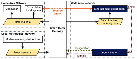
Figure 1.
Communication in the local metrological network (LMN), home area network (HAN), and wide area network (WAN) based on [6,26].
The Smart Meter Gateway administrator (GWA) acts as a trustworthy authority for the SMGW. Each SMGW is assigned to one GWA. Only the GWA is authorized to configure the SMGW and perform administrative functions such as software updates. In order to perform these functions, the GWA can securely communicate with the SMGW using the “management channel”. This channel can be established using the so-called “wake-up service”. All other communication partners of the SMGW in the WAN are external market participants (EMPs). One must distinguish between active and passive EMPs. While the passive EMP only receives metering data, the active EMP (aEMP) is authorized to communicate with one or more CLS in the HAN, using the transparent data tunnel provided by the SMGW. Therefore, the DSMgr is acting in the role of an aEMP. Consumers are the legal entities or natural persons whose consumption is metered. The SMGW is able to distinguish between multiple consumers, in order to preserve their privacy. Each consumer is the owner of their individual meter data and can retrieve them at a designated interface from the SMGW or metering device. For maintenance and to perform diagnostics, the service technician has local access to the SMGW via the HAN interface.
The roles within the SMGW architecture are distinct from the defined market roles within the energy economy. While most of the traditional market roles will act as EMPs in the SMGW infrastructure, e.g., energy suppliers, the role of the metering point operator faces new regulations and requirements. The metering point operator has to equip and operate the iMSys according to the regulations and will, in most cases, act as the GWA.
3.3. Configuration of SMGWs
The functionality described in the technical guidelines is divided into network (i.e., LMN, HAN, or WAN) specific use cases. Furthermore, communication scenarios are specified as implementations of the use cases, where each communication scenario defines specific requirements. An exemplary WAN use case is “administration and configuration”, which is executed by the WAN communication scenario “management”. Furthermore, tariff use cases (“Tarifanwendungsfall”, TAF) define rules that specify which data are measured, the time of measurement, how this data are processed, when they are transmitted, and whom they are sent to. TAF2, for example, reflects a variable time-based tariff. In order to set up all these parameters, there are several types of configuration profiles. WAN and HAN communication profiles define the parameters for the communication with the SMGW in the corresponding communication networks. They also reference a specific communication scenario. Meter profiles configure the communication with metering devices. The processing of meter data is set up in evaluation profiles, which each specify one of the available tariff use cases and comprise data transmission specification. Finally, proxy profiles link WAN and HAN communication profiles to determine which DERs and EMPs are able to use the transparent data tunnel between HAN and WAN [6].
3.4. Secure Bidirectional Communication for Value-Added Services
The transparent data tunnel enables the use of services other than the transmission of meter data to the EMP, and configuration by the GWA. It is the core for designing value-added services, such as smart grid applications. By providing the transparent data tunnel, that is, a secure and bidirectional communication channel, the SMGW acts as mediator between CLS in the HAN and aEMP in the WAN. The utilization of this function distinguishes the active EMP from the passive EMP. The passive EMP only receives meter data and is not allowed to communicate via the transparent data tunnel. There are three HAN communication scenarios (“HAN-Kommunikationsszenario”, HKSs), HKS3, HKS4, and HKS5, for the communication between a CLS and an aEMP.
Each scenario differs in who is responsible for the initiation of the transparent data tunnel. The different steps required are depicted in Figure 2. To configure and establish the transparent data tunnel via the SMGW, a communication profile is required for each CLS and aEMP. The communication profile consists of several parameters, including the IP address and port, the communication scenario, the physical interface of the SMGW, the TLS certificate of the communication partner, and time specifications, such as the maximum duration of the connection. It must be added that the connection must not last longer than 48 h; otherwise the SMGW must reject the communication profile [6]. This means that the transparent data tunnel has to be reestablished at least every second day. Furthermore, a proxy profile is required for all of the HKS3–5. The proxy profile references the HAN and WAN communication profiles and specifies further information depending on the scenario if necessary. A transparent data tunnel may only be established to the end points referenced in the proxy profile and specified in the communication profile. Because of the overall importance for the prototype, in the following, HKS3–5 are described in more detail:
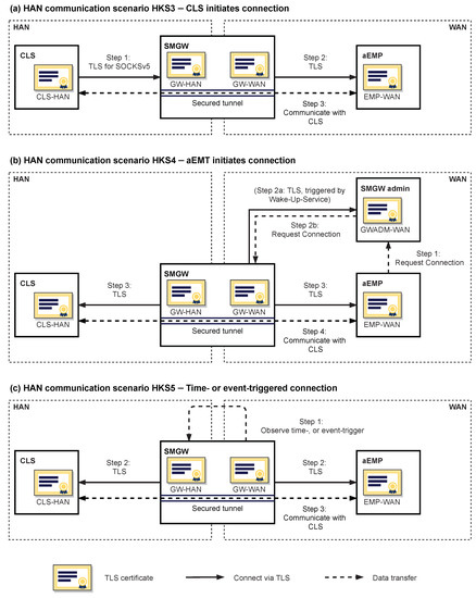
Figure 2.
The three relevant HAN communication scenarios for integrating a decentralized energy management system (EMS), based on [6]. The major difference lies in who initiates the secured communication via the transparent tunnel.
- HAN Communication Scenario HKS3: In HKS3 the CLS initiates the transparent data tunnel using the SOCKSv5 protocol. It implements a proxy server application in which the CLS as client requests the SMGW (the proxy server) to connect to the aEMP. The “TLS for SOCKSv5“ protocol is used for authentication. The complete TLS communication is thus embedded in SOCKSv5 messages. In the WAN the SMGW acts as a TLS client, the aEMP as a TLS server. There are several conditions that need to be met before a connection is established. Firstly, the SMGW must be configured using a communication and proxy profile. Secondly, the parameters of the connection request must match a configured proxy profile; that is, only the CLS referenced in the configuration can request a data tunnel, and it can only connect to an aEMP specified in the profile. Thirdly, a connection is only established if both CLS and aEMP have valid TLS certificates that meet the corresponding SM-PKI requirements and technical guidelines [29,30]. Lastly, the SMGW must possess a HAN and a WAN TLS certificate with the corresponding private keys.
- HAN Communication Scenario HKS4: In HKS4 the aEMP initiates the connection. Since only the GWA is able to contact the SMGW from the WAN, the aEMP needs the help of the GWA to get a connection established. Hence, in the first step, the aEMP contacts the GWA. It is, however, worth noting that there is no standardized interface for contacting the GWA. If the SMGW is not currently connected to the GWA, the wake-up service is used to initiate a TLS connection. Once the SMGW is connected, meaning a “management-channel” is established, the GWA sends the command to establish the transparent data tunnel. The command references the proxy profile which contains the connection parameters for the aEMP and CLS. The SMGW acts as a TLS client in the HAN and in the WAN, and initiates the TLS connections. In this communication scenario, both CLS and aEMP must act as TLS servers and listen for connections. A requirement regarding encrypted communication is that SMGW (for both HAN and WAN interface), aEMP, and CLS have TLS certificates from the SM-PKI and corresponding private keys.
- HAN Communication Scenario HKS5: In the HKS5 the SMGW initiates the channel. The initiation is triggered by time or another event. Once triggered, the SMGW establishes two TLS channels, one to the CLS and one to the aEMP, according to the respective communication profiles. Here, again, the SMGW connects to the CLS and the aEMP as a TLS client. Hence, the data tunnel is established analogously to HKS4.
3.5. Secure Communication within the SMGW Architecture
Not only do the technical requirements have to be considered when integrating an EMS into the SMGW infrastructure, but the extensive security requirements must be as well. The respective specifications are presented shortly and the implications for the prototype are further highlighted. For the SMGW and the security module, the protection profiles defined in [9,10] determine security requirements. The overall communication infrastructure in the WAN underlies the SM-PKI defined in [29,30]. While in [29] the architecture of the SM-PKI and the design of the used certificates within the PKI is illustrated, in [30] all requirements are specified that institutions participating in the SM-PKI have to satisfy according to their roles. The overall architecture consists of three hierarchical layers: The root-certification authority (CA) as trust anchor, the sub-CA as issuer of certificates for end users, and, as the last layer, the SMGW, GWA, and EMP as end users with role specific certificates. Certificates issued to end users are used to guarantee secure communication, integrity, and data privacy. Therefore, the issued certificate set for each end user consists of three certificates with different purposes: the TLS certificate for secured communication, the encryption certificate for information encryption independent of TLS, and the signature certificate to verify integrity independent of TLS authentication. While the three certificates together are needed for most WAN use cases, only the TLS certification is needed for the transparent data tunnel. Additionally, for the SMGW there are two types of certificate triplets. Firstly, during the manufacturing process of the SMGW, so-called quality seal certificates (“Gütesiegelzertifikate”) are stored on the security module. Secondly, to put the SMGW in a productive mode, those certificates have to be replaced with new ones issued from the respective sub-CA for the role SMGW.
Requirements for issuing certificates in the SM-PKI are defined by [30], including technical, personnel, and organizational aspects. The policy distinguishes active and passive EMPs, with higher security requirements for aEMPs. As a comprehensive analysis of all requirements according to all roles surpasses the scope of this paper, we only discuss the most important regulations for companies acting as aEMP in Section 3.6. Additionally, the TR-03109-3 [32] has to be considered, as it technically specifies the cryptographic functions referenced in [29,30]. While the SM-PKI does not cover communication in the HAN, the cryptographic requirements in [32] encompass HAN and WAN communication. Particularly, the use of a selection of elliptic curves and a restriction to five specific cipher suites for the TLS handshake is mandatory. For testing purposes, the BSI defines a second version of the SM-PKI, the so-called SM-Test-PKI with less restrictive security requirements. This SM-Test-PKI can be used to verify the technical compatibility of systems with the SM-PKI.
3.6. Requirements for (Active) EMPs
In order to communicate with DERs located in the HAN, DSMgrs must be certified aEMPs and therefore obtain SM-PKI certificates. The requirements can mainly be summarized as safety requirements for the participation in the SM-PKI. The certification proves that all defined security requirements of the document “Certificate Policy of the Smart Metering PKI” published by the BSI are fulfilled [30]. This includes the employment of an information security management system certified according to ISO/IEC 27001. Furthermore, all private and public keys must be created and stored in a security level 2 cryptography module. Requirements with respect to the security level of cryptography modules are specified in the BSI document “Key Lifecycle Security Requirements” [33]. The cryptography module must also be used for all cryptographic algorithms involved in the communication. Before a company can participate as an aEMP in the SM-PKI, both requirements need to be fulfilled and proof has to be provided to the sub-CA. Only then the sub-CA is authorized to issue signed certificates [30] which are necessary to communicate with the SMGW, in the WAN.
For companies that want to control end devices via the SMGW infrastructure, but are not willing to take the risk of implementing the necessary requirements themselves, there is the alternative option of utilizing a CLS management system. There are already several companies offering the service of an end-to-end communication between WAN and HAN without the need for users to implement the requirements of TR-03109. Providers of CLS management systems take care of all of the communication falling under the TR-03109. To bridge the gap between WAN and HAN, they provide interfaces in both communication networks, which then are no longer part of the regulation. In the WAN, they provide a head-end-system with which the backend of the DSMgr can communicate. This head-end-system implements all regulations and forwards the communication via the SMGW to a local control box or EMS, also provided by the CLS management provider. The device in the HAN forwards the communication to the actual endpoint targeted by the DSMgr; e.g., a DER. This final communication link between DER and CLS is again not touched by the regulation of the TR-03109. Hence, the DSMgr does not need to care about communication regulations at all. Such a setup, using a CLS management system, is outlined in Figure 3. The communication nodes provided by the CLS management are highlighted in purple.
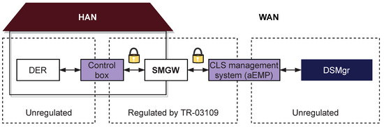
Figure 3.
Controllable local system (CLS) management systems encapsulate SMGW-specific requirements and provide interfaces for DSMgrs that offer a direct communication channel to control boxes.
4. Methodology and Prototype Implementation
In this section we outline the methodology involved in the presented research. The core component for answering the research questions in a practical context is a prototype integrating an automated, decentralized EMS, which controls DERs according to a smart grid traffic light based DSM, into the SMGW infrastructure. In particular, we chose to integrate an electric vehicle charging station and EVs into such a local EMS, as they offer a high potential for increasing grid stability. Since our primary goal was the demonstration of the integration into the SMGW infrastructure, we abstained from adding further DERs. Nevertheless, more DERs could easily be added and managed by the local EMS due to the versatility of the presented architecture described in Section 4.8. Please see the Supplementary Materials provided with this paper for the source code of the implemented prototype, which is described in detail in this section. The key functionality of SMGWs used by this prototype is the provision of a transparent data tunnel for secure and bidirectional communication.
4.1. Evaluation Process and Validation Criteria
The prototype connects the widely researched topic of DSM with the newly introduced SMGW infrastructure, which is becoming an integral part of the energy regulation in Germany. In order to answer the posed research questions, it is necessary to successfully implement and test a DSM approach based on the exploitation of flexibility provided by a decentralized EMS. As stated before, it is neither our goal to propose novel DSM approaches or control algorithms, nor to evaluate their performance. Instead, we provide an analysis of the functionality of these novel communication devices in the context of EMS-enabled DSM. The criteria presented in Table 2 determine whether we consider the prototype to work as intended or not.
Table 2.
Criteria determining whether the prototype works as intended.
The above criteria are specific to the combination of SMGW and HKS. Theoretically, for each SMGW three HKSs can be implemented and evaluated, given the SMGW supports the respective HKS. The prototype is validated step by step based on the criteria, as outlined in the following:
- Configuration
- 1.1.
- Send request for adding new HAN communication profile from GWA to SMGW.
- 1.2.
- Send request for adding new WAN communication profile from GWA to SMGW.
- 2.3.
- Send request for adding new proxy profile from GWA to SMGW.
- Communication
- 2.1.
- Physical setup for connectivity of all components.
- 2.2.
- Align communication infrastructure and configuration profiles (e.g., IP addresses).
- 2.3.
- Start systems of EMS and aEMP.
- 2.4.
- Set the grid state to green.
- 2.5.
- Establish communication utilizing the respective HKS.
- 2.6.
- Validate network traffic.
- Steering by aEMP and control by EMS
- 3.1.
- Connect electric vehicle to charging station.
- 3.2.
- Request charging process via user interface.
- 3.3.
- Validate if charging power is as expected regarding grid state and time-variable prices.
- 3.4.
- Change grid state to yellow.
- 3.5.
- Validate if charging power is as expected regarding grid state and time-variable prices.
- 3.6.
- Change grid state to red.
- 3.7.
- Validate if charging power is as expected regarding grid state and time-variable prices.
- 3.8.
- Stop charging process via user interface.
- Evaluate success
It is worth noting that the prototype implementation and the physical setup can be used with different SMGWs with only minor adjustments such as updated IP addresses. An evaluation run is labeled a success when all steps are performed without errors.
4.2. Overall Prototype Concept
Given the general methodology, now the actual implementation is described independently of the SMGW. Figure 4 shows a schematic overview of the system landscape of the implemented prototype. In our prototype, the EMS uses a heuristic to solve an optimization problem with respect to global incentives in the form of a time-variable electricity tariff, and restrictions received from the aEMP. We decided to consider an EV charging station, since EVs are one major source of flexibility, and are becoming increasingly popular. They are also explicitly named in § 14a of the German Energy Industry Act (“Energiewirtschaftsgesetz,” EnWG) to be considered as consumption devices that can be controlled in a grid-supportive manner. In order to allow the decentralized EMS and the aEMP to communicate with each other, the bidirectional transparent data tunnel provided by the intermediary SMGW is used. Hence, to realize the transmission of the incentives or restrictions, first of all, the communication has to be implemented in a way complying with all the requirements outlined in the previous section. This includes the configuration of the SMGW via the GWA, and the setup of all components in the prototype. Moreover, communication needs to comply with the rules of the SM-PKI.
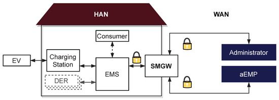
Figure 4.
Outline of the implemented prototype: The decentralized energy management system performs an optimization which is (i) motivated by a dynamic electricity tariff and a potential maximum power limit dynamically received from an active external market participant (aEMP) via the SMGW, and (ii) restricted by consumer inputs representing degrees of freedom for the optimization.
With respect to DSM, we combined two different approaches for the exploitation of flexibility (cf. [34]). Firstly, by implementing quota-based DSM measures, there is no need for generating and communicating a model for flexibility. A quota, in the context of DSM, restricts the maximum consumption (or feed in) to a specified power level (cf. [27,35]). The exact usable power is derived from the traffic light phase given by the smart grid traffic light concept. Secondly, a dynamic electricity tariff is implemented to allow an indirect exploitation of flexibility. Taking a time-of-use electricity tariff into consideration, the EMS determines an economically optimal charging strategy. Both the exact restriction of consumption and the time-variable electricity prices are provided by the aEMP. The charging strategy is determined, taking into consideration the time period available for charging, the requested energy, and the maximally available charging capacity. Requested energy and the time frame of availability are inputs that can be set by the consumer for each charging session via a web interface. The charging station integrated into the prototype is a KeContact P30 c-series from Keba AG. We implemented the prototype and tested the interactions between all components; i.e., EV, charging station, EMS, SMGW, aEMP, consumer interface, and SMGW administrator. Furthermore, we tested multiple SMGW products from different manufacturers. The GWA software was developed by Robotron Datenbank-Software GmbH, and provided as a service running on their own servers. The EMS and the server of the aEMP are implemented as parts of the prototype presented in this paper. Each of these two systems ran on a dedicated Raspberry Pi 3b+. The prototype has been tested with a Smart EQ fortwo and a Tesla Model 3. To be able to evaluate the prototype with different devices, our prototype setup includes a total of seven SMGWs from five different manufacturers. The five manufacturers of the SMGWs are Devolo AG/Kiwigrid GmbH (cooperation), EMH metering GmbH and Co. KG, Landis + Gyr AG, Power Plus Communications AG (PPC), and Theben AG. The PPC SMGW was the first to receive a certification according the SMGW Protection Profile BSI-CC-PP-0073 in December 2018, followed by Sagemcom Dr. Neuhaus in September 2019, and EMH metering in December 2019. All other SMGWs, as of March 2020, are still undergoing certification.
4.3. Integration into the SM-PKI and Configuration of the SMGWs
For the secure communication within the SMGW infrastructure, an integration into the SM-Test-PKI is required as described in Section 3.5. For the prototype setup, a sub-CA signed by the T-Systems’ test-root-CA is utilized. This sub-CA signs GWA certificates, aEMP certificates, and the certificates of the SMGWs. The aEMP certificate contains the elliptic curve public key and uses the “BrainpoolP256r1” elliptic curve domain parameter. Communication in the HAN is outside the scope of the SM-PKI regulation, but several cryptographic requirements must be met by the certificates of the CLS. The HAN certificates are also elliptic curve cryptography certificates generated using NIST P-256 and are self-signed.
In order to initiate the transparent data tunnel and successfully establish a communication channel, it is necessary to configure the SMGW with certain configuration profiles introduced in Section 3.3. During production, each SMGW is initialized with the help of an initial configuration file specifying a GWA and the quality seal certificates. To put the SMGW into productive operation, these initial certificates must be replaced with new certificates created according to [29]. Only then, the necessary configuration profiles can be transmitted to the SMGW.
For the two communication end points, the EMS and the aEMP, a HAN and a WAN communication profile are required [6]. In the HAN communication profile, the most important parameters are the certificates, the specification of one of HKS3–5, and the address as a uniform resource identifier; i.e., a string defining protocol, IP address, and port. The WAN communication profile uses similar parameters, but with a WAN communication scenario instead. The defined WAN communication scenario for the transparent data tunnel is “Info-Report” [6]. Finally, a proxy profile references both communication profiles, and adds specific parameters depending on the HKS (see [6] for more details). While the syntax of the configuration profiles is the same among all manufacturers, the semantics can differ. One example is the specification of the address of the communication endpoint. Some SMGWs require the specification of a protocol, while others do not require this information. Furthermore, the communication scenario descriptions in the WAN communication profile are not identical. While some manufacturers require the “Info-Report” described in TR-03109, others require the specification of a custom WAN-CLS scenario, which is not a part of the TR-03109. Additionally, the implementation of proxy and communication profiles can deviate from the TR-03109, and instead follow the specifications “Smart Meter Gateway: Functional Features” [36] released by the Forum Grid Technology/Grid Operation (“Forum Netztechnik/Netzbetrieb,” FNN). In summary, many specifications of the technical guidelines are implemented in the individual devices, but different devices can produce quite different results, which also may deviate from the TR-03109.
4.4. Establishing a Transparent Data Tunnel
In addition to the physical setup, the systems of the aEMP and the EMS must be implemented. Both systems are developed and implemented in different versions for each of HKS3–5. The applications are implemented in Python using the module pyOpenSSL for operating TLS. PyOpenSSL is a wrapper for using the popular OpenSSL library. The free software implements the TLS protocol and a variety of cryptographic functions. For the aEMP, in all three scenarios, HKS3–5, a TLS server must be present. The aEMP communicates with the SMGW via the protocol TLS1.2 using cipher suite “TLS_ECDHE_ECDSA_WITH_AES_128_CBC_SHA256”. The certificates signed by the sub-CA, and the sub-CA certificate to authorize the certificate chain, must be secured in the system of the aEMP. Regarding the EMS, while HKS4 and HKS5 both also require a TLS server, HKS3 needs a client application in which the SOCKSv5 protocol is implemented. Within the SOCKSv5 protocol, the authentication method “TLS” must be used according to ([6], p. 61ff). This method further requires a specific sub-negotiation process according to “SSL for SOCKSv5” protocol [37]. The TLS connection established within the SOCKSv5 protocol uses cipher suite “TLS_ECDHE_ECDSA_WITH_AES_256_GCM_SHA384”. We did not find any SOCKSv5 implementation for Python incorporating this sub-negotiation, so both protocols are self-implemented (see Supplementary Materials). In this process, firstly, the CLS connects via SOCKSsv5 to the SMGW and requests authentication using “SSL for SOCKSv5”. Secondly, a TLS tunnel is established, and therefore, the following communication is encrypted. Finally, the CLS requests a connection to the aEMP. The whole communication sequence is implemented following the requirements specified in ([6], p. 61).
4.5. The Smart Grid Traffic Light Concept
Different parties are interested in utilizing the flexibility that can be provided by DERs. For example, electricity suppliers with access to the wholesale electricity market can use flexibility for cheaper procurement of energy, or distribution system operators that are interested in guaranteeing grid stability can use flexibility to keep voltage within a valid range or to prevent transformer overloads. Due to different parties interested in accessing flexibility provided by DERs, smart grid traffic light concepts provide a model for the interaction between market participants and grid operators. Different definitions of smart grid traffic light concepts exist, such as [22]. A comprehensive discussion of this concept can be found in [38]. In general, following the logic of a traffic light, at least three traffic light phases are defined, with the default being the green phase. During a green phase, there are no restrictions, only incentives. Yellow phases introduce some constraints, and red phases allow massive interference. The yellow or red phase can be activated according to the needs of the electrical grid. Such a need is usually identified by the (distribution) system operator. In the SMGW infrastructure, the implementation of demand response measures requires the role of the aEMP. In our implementation we use one aEMP to transmit the traffic light phases. However, depending on the future system design, it is worth noting that two aEMPs could be used. One could represent an electricity supplier providing time-variable prices being in control in the green and yellow phase, and the other could represent a (distribution) system operator being in control in the yellow and red phase, ensuring grid stability. For our prototype, in the green phase charging is allowed at maximum power without any limitations. In the yellow and red phases, the charging power is limited to individual maximum threshold values. In this paper, we only consider the limitations of the power consumed in the yellow and red phases, which implies grid instability due to insufficient supply. In general, however, the yellow and red phases can also be activated due to oversupply, for instance, as a result of temporary high generation by renewable energy sources. Furthermore, if we added more DERs, the EMS could try to satisfy these constraints without throttling or interrupting the charging process, as it would be sufficient to consider the total demand of all DERs.
In our prototype implementation, a communicated traffic light phase lasts until another change is communicated by the aEMP. In the green phase, the EMS optimizes based on the daily time-variable electricity prices that are communicated to the EMS from the aEMP via the secure communication channel. It provides electricity prices (in € per kWh) for each of the upcoming 72 h. Based on the provided consumer restrictions (availability of the EV and required energy), the EMS minimizes the charging costs over the respective charging period by gradually choosing the cheapest time intervals for charging until the required energy is reached. In the green traffic light phase, this happens without further limitations. In the yellow traffic light phase, we chose the aEMP to request a fixed power limit; that is, a maximum of 6 kW in our prototype. This limit is then considered by the EMS in its optimization. In the red phase, we chose the aEMP to request the complete interruption of the charging process; i.e., to curtail the charging to 0 kW.
4.6. Implementation of the Decentralized EMS
The automated decentralized EMS is responsible for managing the charging process, while considering user inputs and the restrictions posed by the DSMgr. In order to do so, the EMS receives global parameters from the aEMP and commands from the consumer, optimizes the charging strategies, and sends control signals to the charging station. To be able to collect user inputs, the EMS includes a web interface for interacting with the inhabitant of the building; i.e., the consumer. Via the web interface, the consumer can start and stop the charging process, and give the necessary information for the cost optimization; that is, the time span until the EV leaves for the next ride and the desired energy to be charged. Furthermore, the automated EMS receives daily updated time-variable electricity prices for the next 72 h, and real-time smart grid traffic light signals from the aEMP. Depending on the grid state, which is reflected in the traffic light phase, the EMS must adjust the power to the requested level. Taking the stated parameters into consideration, the automated EMS determines the charging strategy exhibiting minimal costs by solving an optimization problem. Due to the simple problem structure, it is possible to compute the optimal charging strategy with the help of a heuristic. The optimal solution is found by sorting the time steps by the associated price and repeatedly scheduling charging powers until the desired amount of energy is reached. As the focus of this paper lies on the SMGW infrastructure rather than the approaches for DSM and energy management, we refer to the source code provided with this paper for further information regarding this heuristic. The strategy is updated constantly to respond to new grid states, and the EV charging station is controlled accordingly. By sending suitable time-variable electricity prices to the consumer, the presented optimization enables the DSMgr to exploit the flexibility of the charging station.
The individual components of the EMS, that is, the optimization and scheduling logic, the user interface, and the communication handler (ComHandler), exchange information via a message broker. As message broker, Mosquitto (https://mosquitto.org/) is used, which implements the “MQTT” protocol [39]. MQTT provides a publish and subscribe mechanism for exchanging information. Data are published to so-called topics, and each subscriber of the specific topic receives the data. The protocol is used internally, and externally for the communication with the aEMP, using the offered bridge function of MQTT. Yet, the ComHandler module is needed as an additional interface between Mosquitto and the SMGW. Depending on the HKS3–5 used, the ComHandler has to be adjusted. For HKS3, the ComHandler encrypts the MQTT message within the TLS protocol, wraps it in the SOCKSv5 protocol, and sends the message to the SMGW. From the aEMP, it receives messages via the SMGW, decrypts the data, and sends the decrypted MQTT message internally to the message broker. Furthermore, the ComHandler ensures that the connection to the aEMP remains open. If the connection is disrupted, the ComHandler automatically tries to restart the connection by requesting a new initiation of the transparent data tunnel. For HKS4 and HKS5, the ComHandler encrypts the message within the TLS protocol and sends it directly to the SMGW. However, in HKS4 and HKS5 the ComHandler embodies a TLS server and can only communicate with the SMGW if a connection is opened by the SMGW.
4.7. Implementation of the Active EMP
The implemented functions of the aEMP are the distribution of the time-of-use electricity prices as an exemplary use of the transparent data tunnel, the monitoring of the status of the EMS, and the communication of the grid state according to the smart grid traffic light concept. The first function is the transmission of the time-of-use electricity prices. In our prototype we use historic electricity prices from the German European Power Exchange day-ahead market, adjusted by grid fees and taxes, and send them to the automated EMS once a day. Furthermore, the grid state is communicated each time the connection to the EMS is established, or if a change of the smart grid traffic light phase takes place. As the prototype is encapsulated from other systems, for the scope of the prototype, it is sufficient to manually set the grid state in the systems of the aEMP. The aEMP software is built in a modular fashion with multiple components interconnected via a message broker. If a grid state change is detected, a message is published to Mosquitto. The ComHandler, analogously to the EMS, acts as mediator between message broker and SMGW. It encrypts all outgoing traffic to the SMGW and decrypts all incoming traffic to the message broker. The ComHandler embodies, for all three HKS3–5, a TLS Server, waiting for the connection request from the SMGW. From the automated EMS, the aEMP receives different selected states, like the state of the charging station, the current charging power, and the consumer’s requests. The received information is stored in a time-series database by the aEMP. As database, we use InfluxDB (https://www.influxdata.com/). The aEMP can use this data to visualize the grid states and the power flows with Grafana—open source software for analytics and interactive visualization (https://grafana.com/). In that way the aEMP can also track whether the EMS acts according to the transmitted grid state.
4.8. Integration of All Components
A detailed overview of the implemented prototype is given by Figure 5. To conclude, we chose a service-oriented architecture in order to build a modular and extensible framework. The individual components such as the user interface exchange information via the application protocol “MQTT”. With the help of the two ComHandlers, the interaction between the EMS and the aEMP is also implemented on basis of an MQTT bridge between both message brokers.
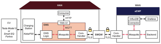
Figure 5.
Detailed overview of the individual prototype components. Italics are used to mark names of products.
For the HKS3-based communication from the aEMP to the EMS, the MQTT protocol is encrypted via TLS between the aEMP and the SMGW, and via SSL for SOCKSv5 between the SMGW and the EMS. In the prototype, we integrated a charging station as exemplary DER. The crucial function we focus on is the transparent data tunnel. This function is used to enable a secured bidirectional communication between the aEMP and the decentralized automated EMS. The aEMP adds restrictions to the local optimization conducted by the EMS, which controls the charging according to the consumer’s needs and provides flexibility (time of departure, energy to be charged till departure). When replacing the heuristic with a suitable optimization model, further DERs could be integrated easily due to the use of MQTT as the application protocol that supports the efficient exchange of information between many entities. The necessary steps are, firstly, the definition of a shared data format for exchanging states and schedules; secondly, the integration into the optimization problem; and lastly, the actual implementation. This needs to be repeated for each new type of DER. Regarding the constraints dictated by the aEMP, the individual (contractual) restrictions may have to be updated. Aside from this change of parameters, i.e., the maximum power during the yellow or red phase, the employment of this restriction based demand response scheme makes it possible that no further steps are required by the aEMP. Moreover, adding further DERs does not require updates of any SMGW-specific configurations.
5. Results and Discussion
With the presented prototype, we were able to successfully integrate the outlined EMS into the SMGW infrastructure. We demonstrated the optimized charging of two different EVs and successfully implemented the restrictions instructed by the DSMgr. While this work does not aim to introduce new, advanced DSM measures, it joins two predominant topics; namely, smart metering in the context of the German smart meter infrastructure and DSM, and provides a detailed technical assessment how to unite both. Using the hardware setup outlined in this paper, multiple SMGWs have been tested according to the formulated methodology, uncovering specifics that need to be considered when developing value-added services in the SMGW infrastructure.
5.1. Implications of the Choice of the HAN Communication Scenario
All three relevant HAN communication scenarios have been implemented and tested according to the introduced methodology, given the SMGW was compatible with the HKS. The HKS3, HKS4, and HKS5 have been implemented for the PPC SMGW and the HKS4 and HKS5 for the Devolo/Kiwigrid SMGW. For each HKS exemplary configuration profiles can be found in the Supplementary Materials. However, the implementation of the scenarios for each manufacturer showed that interoperability, a core objective of the TR-03109, is not guaranteed on the implementation level. In the course of the development of our prototype, the interaction and interfaces between GWA, SMGW and DSMgr/aEMP have been a main cause for implementation difficulties. In cooperation with the respective parties, the individual systems had to be extended. Discrepancies between the systems are based on the fact that interoperability is mainly addressed on a conceptual level and only to a limited degree on the implementation level. Furthermore, although the syntax of the communication profiles among the different SMGWs is the same, the semantics differ. An example is the specification of the destination address in the communication profile, where some SMGWs require a protocol specification (such as “https” in addition to an IP address and a port), and others do not. To put it in the wording of RFC 3986, sometimes a scheme is required in addition to authority, sometimes not. This results in a different behavior of different SMGWs regarding the acceptance or rejection of profiles. The main insights for each of HKS3–5 are illustrated in the following:
- HKS3 (CLS initates connection): HKS3 is special in that it uses the SOCKSv5 protocol. This brings additional complexity, because a draft version of protocol “SSL for SOCKSv5” is used for authentication. Our implementation showed that the SMGWs not necessarily act according to the protocol. If the protocol requirements are strictly implemented, these problems should no longer occur in the certified SMGWs. The advantage of the HKS3 is its independence from the GWA. The necessary configuration profiles must be uploaded to the SMGW once, after which the transparent data tunnel can be initiated from the HAN whenever and as often as necessary. Only in cases of structural changes to the communication setup are new configurations necessary. Especially in consideration of the aspect that the aEMP needs the GWA as a service provider, the greatest possible independence is desired. Considering profitability, higher dependence will probably also have an impact on the service fees paid to the GWA. Furthermore, assuming the CLS is developed by the DSMgr, the DSMgr can define when and how often the transparent data tunnel is initiated by the CLS without relying on a third-party company as in HKS4 and with a higher degree of freedom opposed to HSK5. Considering that for many applications a continuously open communication channel is desired, two scenarios have to be distinguished. Firstly, a planned, scheduled re-establishment of the transparent data tunnel can be realized by predefined rules configured in the CLS, or can be actively triggered by the DSMgr via already established communication. Secondly, an unplanned re-establishment, e.g., in case of interruptions of the communication, can follow predefined rules configured in the CLS. This way, in HKS3, the CLS instance (and thus the DSMgr), can implement and control the re-establishment of the data tunnel according to their individual needs. In the cases of HKS4 and HKS5 this is different and a potential issue, as discussed in the respective sections below. Another relevant aspect is that each connection may be open for a maximum of two days before it is closed by the SMGW. This means that the transparent data tunnel must be re-initiated after a maximum of two days. Taking the system design into consideration, the traffic in the WAN is minimized as the connection is initiated in the HAN. This becomes particularly relevant if the WAN communication includes cellular networks or broadband power line communication. It is conceivable that, in the future, several different applications, not necessarily only by one company, use the SMGW as entry point to the HAN. Therefore, a minimization of the traffic in the WAN is preferable.
- HKS4 (aEMP initiates connection): The HKS4 comes with a large dependence on the GWA. The configuration is required only once, but for each initiation of the communication channel the GWA needs to be contacted by the aEMP. Via the management channel between SMGW and GWA, the GWA sends the initiation command from its system to the SMGW, which then establishes the TLS channel. This adds a further step into the chain of commands, and means added complexity and thus a higher error-proneness and latency. The resulting dependency on the GWA and respective communication services will probably be reflected in the costs for the operation of the GWA system. Again, it is worth noting that the transparent data tunnel must not be open for more than two days. Hence, this interface needs to be called at least every two days and for each CLS, in cases where a permanent connection is needed. Furthermore, this GWA interface is only defined on a conceptual level in the BSI TR-03109-6 [40] and there are no binding specifications regarding the practical implementation on a protocol level. Therefore, every GWA system may offer its own proprietary interface. In general, third-party companies do only have little influence in regard to which GWA is responsible for the installed SMGWs. Therefore, the lack of standardization could result in a large number of interfaces to be implemented. This leads to increased development and maintenance costs.
- HKS5 (SMGW initiates connection time- or event-triggered): For HKS5, the configuration of the SMGW is required once and afterwards the communication is independent from the GWA. Instead, there is a dependence on the SMGW. The HKS5 only establishes a transparent data tunnel when triggered by time or another event. Events may be particularly important to reestablish the connection in case of errors causing the communication channel to close. As BSI TR-03109-1 [6] only mentions non-time based events and does not further concretize them, practical implementations can vary between SMGW manufacturers. In [36], so-called quality of service parameters for communication profiles are defined in this context. The parameters define how connections are recovered. However, it is difficult to cover all possible environmental conditions with a limited parameter set.
Based on this discussion, for an aEMP, HKS3 is generally the preferable communication scenario, due to the ability to self-decide the times communication is initiated, and the decreased dependence on the GWA. With respect to HKS4, especially the missing technical standardization of the communication between GWA and aEMP is a difficulty, as there are currently 39 different certified GWAs [14].
According to the device profiles specified in [31], SMGW manufacturers only have to implement one of the HKS3–5 for the first generation of SMGWs. Table 3 shows which of the options are implemented by the SMGWs according to the manufacturer’s specifications. No single HKS of HKS3–5 is implemented by all first generation SMGWs, and hence it is necessary for applications (and thus CLS and aEMPs) to implement several HKS if they want to be interoperable and target SMGWs from multiple manufacturers. This is particularly important for third-party companies, who aim to offer value-added services using the transparent data tunnel, as they have little influence on which SMGW will be installed. Hence, not implementing all of the HKS3–5 or the selection of a specific SMGW can massively impact the marketability of products. Regardless of the HKS, it can be stated that the support of multiple HKSs leads to higher development and maintenance costs. A possible way of avoiding the implementation of further HKS would be to make use of the option to change the metering point operator running the SMGW via the well-defined market process. This way, a third-party company providing value-added services could limit its interoperability to certain metering point operators, and hence enforce the installation of only SMGWs of manufacturers supporting certain HKS. The change of an installed SMGW and metering point operator, however, is associated with high effort and costs, as the metering point operator is the owner of the installed iMSys. Interoperability, as one major purpose for the detailed technical requirements, is therefore not granted.
Table 3.
HAN communication scenarios (“HAN-Kommunikationsszenario”, HKS) implemented by SMGW manufactures. No statement was acquired from EMH metering, Discovergy, and Landys + Gyr.
Even though the first certified SMGW from PPC offers all three HKSs, the second certified SMGW from Sagemcom Dr. Neuhaus does not match these features and only offers HKS4 and HKS5. Hence, real world application building on top of HKS3 is not possible with this first certified SMGW offered by Sagemcom Dr. Neuhaus. In summary, we demonstrated that a secured bidirectional channel can be set up with the help of the SMGW, and that the infrastructure can be used by DSMgrs to securely connect to EMSs or DERs in order to exploit their flexibility or monitor their operation. However, the exact implementation depends on which HAN communication scenario is used, and yet not all of them are supported by all SMGW manufacturers.
5.2. Implications of Regulation and Certification
5.2.1. Regulation Regarding the Application Layer
The BSI TR-03109 was mainly designed from a security and technical perspective. Value-added services based on the usage of the bidirectional communication channel have not yet been specified; i.e., so far, there was no special focus on the specification of the application layer. However, aiming at interoperability and maximum security, it is unclear whether the BSI will regulate interfaces and processes for further use cases in the future. For controlling CLSs, such as DERs and EMSs, mandatory application protocol requirements are explicitly not included in the technical guidelines. This means that apart from the mandatory utilization of an encrypted TLS connection, application protocols may freely be selected and specified. There are no regulatory application layer restrictions concerning the communicated data or the interfaces provided by CLSs. This could provide opportunities in which the market itself rather than the regulator comes up with innovative solutions and new business models involving the usage of the bidirectional communication channel for application layer protocols. The competition between innovative solution providers will emerge in new economically useful business models. Therefore, binding restrictions regarding the communication on the application layer would hinder the development of innovative solutions and business models required for the economically sensible integration of DERs. To some extent this is also visible in our prototype implementation, which shows that there are different meaningful options of how the communication between EMSs and aEMPs can be implemented in an effective and efficient way. Furthermore, application layer restrictions would have to be use case specific, as the communication channel is explicitly intended to be used not only for smart-grid-related control functionalities, such as the control of DERs or EMSs, but also for further value-added services in the context of smart homes and smart buildings, such as services for assisted living (cf. [41]).
5.2.2. Alignment with Further Regulations in the Energy Industry
A major factor for the acceptance of SMGWs by solution providers, such as DSMgrs, is the certainty that SMGWs as a platform will be classified as appropriate for all possible business cases within the energy industry. Therefore, the SMGW ecosystem should be well aligned with further regulations and market processes in the energy industry. For example, it should be possible to utilize the SMGW platform to satisfy all needed requirements for the provisioning of ancillary services with DERs. Consider, for instance, the pre-qualification criteria by the German transmission system operators regarding the communicative connection. One restriction in this context is the maximum duration of the connection between CLS and aEMP, which is limited to 48 h. After this time frame, the transparent data tunnel needs to be re-established. This may be an important factor for applications that require (near) real-time responses in the area of seconds as the reestablishment of the communication temporarily leads to a short unavailability. The alignment of SMGW-related regulation and other regulations in the energy sector is also addressed in the standardization strategy [41] of the BSI and the German Federal Ministry for Economic Affairs and Energy (BMWi).
5.2.3. CLS Device Certification
So far, there are no BSI requirements regarding the certification of CLS devices. However, this may be subject to further changes as it is intended that DERs are controlled by aEMPs via SMGWs, and form part of a critical infrastructure, namely the power supply. Therefore, a critical evaluation which considers the amount of device installations and the related accumulated power is needed. It has to be considered that implications of a CLS device certification highly depend on the scope of the potential certification; i.e., the level of detail assessed. In general, one argument for certification is that certified CLS devices have the potential to protect the user’s privacy and increase the overall power system security and reliability. However, it has to be noted that device certification also transfers the responsibility from the solution provider to the certifying authority. Hence, certification also tends to lower the device provider’s intrinsic motivation to keep the certified system up to date once the certification is reached. Finally, it has to be assumed that CLS certification would significantly slow down the development of new SMGW-based solutions which already comes with high barriers.
5.3. Implications of Standardization
Based on the insights from developing the prototype, we subsequently discuss advantages and disadvantages of a potential standardization of CLS control boxes that mediate between aEMPs and DERs. In the regulation, the design of a control device acting as middleware to DERs is not addressed. Despite the above discussed need to freely design the application layer protocol to foster innovation, standardization can bring benefits in use cases where a large set of DERs is controlled based on an identical command set. One concrete example for such a use case is the control of DERs that are controllable according to § 14a of the EnWG like heat pumps, night storage heater, or EV charging stations. Based on the named law, energy consumers pay lower grid fees when they give distribution system operators a certain authority over the control of their DERs. To this day, this is realized by ripple control. Usually, a dedicated ripple control receiver is used for receiving demand response commands which trigger state changes of one or two relais, thereby allowing one to switch between different operational states of the connected DERs. For example, power inverters of (rooftop) photovoltaic power plants can be operated in four states based on two relais: 100%, 60%, 30% or 0% of the maximum possible feed-in power. As in such use cases, an interface to a large number of DERs with almost identical control options is required, the SMGW-based control via a dedicated application protocol can be meaningful. However, in this context, it is worth noting that § 14a EnWG is expected to be subject to major changes in the near future [14,42], and that these changes could incentivize the usage of EMSs that control multiple DERs on their own [35].
The FNN is an industry-representing committee of the German VDE Association for Electrical, Electronic and Information Technologies, which is—among other things—working on standardizing a CLS control box [43], and communication concepts. In this context, the FNN has published two notes, [44,45], and a concept [46], mainly describing processes and requirements concerning the application layer on top of the transport layer. Special emphasis is put on the coordination between market participants and grid operators ensuring grid stability. In particular, the proposed coordination function in [45] is intended to ensure a regulated use of DERs. It is crucial to understand the significant difference between such a control box as it is proposed by the FNN and an EMS: the control box only forwards and translates control signals (or more advanced information such as price signals), while an EMS implements algorithms for the intelligent control based on the received parameters. In order to allow for the development of advanced energy management solutions that are not in scope of the FNN consortium, such as electricity market based optimization beyond pure time-of-use price signals, or the provisioning of ancillary services, it seems important to allow the development and usage of alternative CLS solutions.
5.4. Implications Regarding Data Privacy
With respect to data privacy, it can further be discussed to which extent the transparent data tunnel can be used to gain access to sensitive consumer data. Depending on the implementation of the CLS endpoint in the HAN and the contract with the customer, an aEMP may get access to plentiful sensitive data. In the case of DERs being controlled and monitored, the aEMP knows exactly when and how the DERs have been used. This information can be exploited to derive more sensitive data; e.g., detecting occupancy from consumption patterns. Furthermore, consumers can grant access to the SMGW’s consumer interface to CLSs, e.g., to make high resolution meter measurements available to the CLS. If an aEMP asks for access to the consumer interface and the consumer grants it, the aEMP’s CLS can access sensitive data and transmit it to the associated aEMP via the data tunnel. This would bypass the restrictions dictated by the tariff use cases. However, it is worth noting that this can be done only intentionally, as the consumer interface is secured and the data are only accessible after authentication. Hence, consumers need to actively allow the data access by providing their credentials. When drafting a contract between the aEMP and the CLS customer, it may therefore also be necessary to regulate the accessibility to the consumer interface. Further, if access to the SMGW’s consumer interface is granted to an aEMP, it may be sensible to protect the customer by prohibiting to share the received data with third-party companies.
Finally, regarding the introduced CLS management systems in Section 3.6, further security concerns arise. As shown in Figure 3, the communication between the CLS management system provider and the DSMgr in the WAN is not regulated by the TR-03109. Therefore, this part of the communication chain is not subject to the security requirements, resulting in a possible unsecured communication between EMS and DSMgr. Furthermore, all other requirements are not binding either, including the certification according to ISO 27001. As a consequence, a false sense of security and privacy may be provided to consumers.
6. Conclusions
As a result of the definition of a compulsory smart meter rollout by the EU parliament in 2009, the rollout of SMGWs in Germany started in February 2020. We showed that SMGWs are certified communication modules enabling a secure communication between meters and controllable devices on the one side, and external entities on the other side. According to the German rollout plan, standardized SMGWs will be broadly available in the near future and provide interfaces that can be used by EMS developers and providers. Even though SMGWs are currently specific to the German market, they could gain international importance, due to their distinct features, including the high security standards. On basis of this standardized infrastructure, we presented a proof of concept for the realization of DSM measures with the help of decentralized EMSs. Furthermore, we showed that the key functionality of SMGWs used for the implementation of such a value-added service is the provision of a transparent data tunnel for secure bidirectional communication.
The first research question asks how DSM via a decentralized EMS can be implemented within the German SMGW infrastructure, and for the required design choices. To answer this question, we gave insights into technical details of the presented SMGW-based prototype. It implements a smart grid traffic light based DSM concept with variable electricity prices. We showed how the EMS handles charging processes and controls a charging station according to a cost-optimal charging strategy. The transparent data tunnel is used by the aEMP to send two kinds of information to the EMS: on a daily basis updated time-variable electricity prices, and in real time the current smart grid traffic light phase. Overall, the prototype comprises an SMGW, a GWA, an aEMP, and an automated EMS as CLS which manages and optimizes an EV charging station. Our implementation is based on a flexible hardware setup. It sets the foundation to evaluate the prototype with SMGWs from multiple manufacturers. We covered all of the three different communication scenarios, HKS3–5, that are available for establishing the transparent data tunnel and evaluated specific advantages and disadvantages. The source code for the EMS and the aEMP can be found in the supplementary materials (see note below). We argue that, for a DSMgr, HKS3 is generally the preferable communication scenario due to the highest degree of independence from the GWA.
The second research question asks to which extent the SMGW infrastructure protects private data when integrating an EMS. To answer this question, the presented prototype was implemented in full compliance with not only technical but also security-related requirements. We used a certified GWA system and certificates from the SM-Test-PKI. Our prototype demonstrates that an aEMP can access sensitive data independent of tariff use cases if the user provides the consumer interface access to EMS. Therefore, we argue that the achieved level of privacy depends on the proper usage of the defined security mechanisms. This may in particular require bilateral contracts between the user of a CLS and the aEMP which cannot be technically enforced.
The third research question asks where standardization hinders or supports the integration of EMS into the SMGW infrastructure. SMGWs provide standardized interfaces for communication with external parties and for access to meter data, hence minimizing costs for the operation of EMS. While all functionalities of intelligent metering systems aim to be interoperable, we showed that, at the implementation level, substantial differences between the SMGWs of the different manufacturers can be recognized. We point out that a major source of uncertainty for DSMgrs is that only one of the three HKS3–5 has to be implemented by the first generation of SMGWs. This can result in either higher development costs, or more complex market process for the provision of services. We conclude that the platform should be aligned with further regulation in the energy industry, for instance regarding existing requirements for the provisioning of ancillary services via DERs.
Future work regarding the realization of EMSs as CLSs in the SMGW ecosystem must address the design of application layer protocols in more detail. Open questions can particularly be recognized in the context of the integration of today’s “flexibility markets”. Furthermore, depending on the HKS, we identified a certain communication overhead. Therefore, it seems meaningful to further investigate implications regarding the timing overhead of SMGW-based communication. Finally, emphasis should be put on harmonizing existing interfaces on the implementation level, as such uncertainty hinders the development of new solutions on top of the SMGW infrastructure.
Supplementary Materials
A ZIP archive containing the source code of the EMS and aEMP components is available online at https://www.mdpi.com/2076-3417/10/11/3665/s1.
Author Contributions
Conceptualization, N.K., K.F., and M.L.; methodology, N.K. and K.F.; software, N.K.; validation, K.F.; investigation, N.K.; resources, H.S.; data curation, N.K.; writing—original draft preparation, N.K., K.F., and M.L.; writing—review and editing, N.K., K.F., M.L., and H.S.; visualization, K.F.; supervision, H.S.; project administration, H.S.; funding acquisition, H.S. All authors have read and agreed to the published version of the manuscript.
Funding
We gratefully acknowledge the financial support from the Federal Ministry for Economic Affairs and Energy (BMWi) for the project C/sells (funding no. 03SIN121).
Acknowledgments
We thank Birger Becker for the assistance with the hardware installation and expertise that assisted the research.
Conflicts of Interest
The authors declare no conflict of interest. The funders had no role in the design of the study; in the collection, analyses, or interpretation of data; in the writing of the manuscript, or in the decision to publish the results.
Abbreviations
The following abbreviations are used in this manuscript:
| aEMP | Active External Market Participant (“aktiver Externer Marktteilnehmer”) |
| AMI | Advanced Metering Infrastructure |
| BSI | Federal Office for Information Security (“Bundesamt für Sicherheit in der Informationstechnik”) |
| BMWi | Bundesministerium für Wirtschaft und Energie (“Federal Ministry for Economic Affairs and Energy”) |
| CA | Certificate Authority |
| CLS | Controllable Local System |
| DER | Distributed Energy Resource |
| DSM | Demand Side Management |
| DSMgr | Demand Side Manager |
| EEG | Renewable Energy Act (“Erneuerbare-Energien-Gesetz”) |
| EMS | Energy Management System |
| EMP | External Market Participant (“Externer Marktteilnehmer”) |
| EnWG | Energy Industry Act (“Energiewirtschaftsgesetz”) |
| EV | Electric Vehicle |
| FNN | Forum Grid Technology/Grid Operation (“Forum Netztechnik/Netzbetrieb”) |
| GWA | Smart Meter Gateway Administrator |
| HAN | Home Area Network |
| HKS | HAN Communication Scenario (“HAN-Kommunikationsszenario”) |
| iMSys | Intelligent Metering System (“Intelligentes Messsystem”) |
| LMN | Local Metrological Network |
| MsbG | German Metering Point Operation Law (“Messstellenbetriebsgesetz”) |
| mME | Modern Metering Device (“Moderne Messeinrichtung”) |
| MQTT | Message Queuing Telemetry Transport |
| PKI | Public Key Infrastructure |
| RFC | Request for Comments |
| SMGW | Smart Meter Gateway |
| SM-PKI | Smart Meter Public Key Infrastructure |
| SSL | Secure Socket Layer |
| TAF | Tariff Use Case (“Tarifanwendungsfall”) |
| TLS | Transport Layer Security |
| TR | Technical Guideline (“Technische Richtlinie”) |
| WAN | Wide Area Network |
References
- The European Parliament and European Council. Directive 2009/72/EC of the European Parliament and of the Council: Common Rules for the Internal Market in Electricity and Repealing Directive 2003/54/EC; European Union: Brussels, Belgium, 2009. [Google Scholar]
- Edelmann, H.; Kästner, T. Kosten-Nutzen-Analyse für einen flächendeckenden Einsatz intelligenter Zähler. In Studie im Auftrag des Bundesministeriums für Wirtschaft und Energie; Bundesministerium für Wirtschaft und Energie: Berlin, Germany, 2013. [Google Scholar]
- Bundestag. Gesetz zur Digitalisierung der Energiewende; Bundesanzeiger Verlag GmbH: Köln, Germany, 2016. [Google Scholar]
- Bundestag. Gesetz über den Messstellenbetrieb und die Datenkommunikation in Intelligenten Energienetzen (Messstellenbetriebsgesetz, MsbG); Bundesanzeiger Verlag GmbH: Köln, Germany, 2016. [Google Scholar]
- Bundesamt für Sicherheit in der Informationstechnik. Allgemeinverfügung zur Feststellung der Technischen Möglichkeit zum Einbau Intelligenter Messsystem; Bundesamt für Sicherheit in der Informationstechnik: Bonn, Germany, 2020; Az: 610 01 04 /2019_001.
- Bundesamt für Sicherheit in der Informationstechnik. Technische Richtlinie BSI TR-03109-1: Anforderungen an die Interoperabilität der Kommunikationseinheit Eines Intelligenten Messsystems; Bundesamt für Sicherheit in der Informationstechnik: Bonn, Germany, 2013.
- Ghosal, A.; Conti, M. Key Management Systems for Smart Grid Advanced Metering Infrastructure: A Survey. IEEE Commun. Surv. Tutor. 2019, 21, 2831–2848. [Google Scholar] [CrossRef]
- Yao, J.; Venkitasubramaniam, P.; Kishore, S.; Snyder, L.V.; Blum, R.S. Network topology risk assessment of stealthy cyber attacks on advanced metering infrastructure networks. In Proceedings of the 2017 51st Annual Conference on Information Sciences and Systems (CISS), Baltimore, MD, USA, 22–24 March 2017; pp. 1–6. [Google Scholar] [CrossRef]
- Bundesamt für Sicherheit in der Informationstechnik. BSI-CC-PP-0073-2014: Protection Profile for the Gateway of a Smart Metering System/Schutzprofil für die Kommunikationseinheit eines Intelligenten Messsystems für Stoff- und Energiemengen; Bundesamt für Sicherheit in der Informationstechnik: Bonn, Germany, 2014.
- Bundesamt für Sicherheit in der Informationstechnik. BSI-CC-PP-0077-V2: Protection Profile for the Security Module of a Smart Meter Gateway (Security Module PP)/Schutzprofil für das Sicherheitsmodul der Kommunikationseinheit eines Intelligenten Messsystems für Stoff- und Energiemengen; Bundesamt für Sicherheit in der Informationstechnik: Bonn, Germany, 2015.
- Herre, J.; Freunek, M. Intelligente Messsysteme—Alternativen zum Smart Meter Rollout. In Realisierung Utility 4.0 Band 2: Praxis der Digitalen Energiewirtschaft vom Vertrieb bis zu Innovativen Energy Services; Springer: Wiesbaden, Germany, 2020; pp. 195–213. [Google Scholar] [CrossRef]
- Bachor, M.; Freunek, M. IoT-Lösungen als Alternative zum klassischen Smart Metering. In Realisierung Utility 4.0 Band 2: Praxis der Digitalen Energiewirtschaft vom Vertrieb bis zu Innovativen Energy Services; Springer: Wiesbaden, Germany, 2020; pp. 215–226. [Google Scholar] [CrossRef]
- Bundesamt für Sicherheit in der Informationstechnik. Marktanalyse zur Feststellung der Technischen Möglichkeit zum Einbau Intelligenter Messsysteme nach § 30 MsbG; Version 1.0; Bundesamt für Sicherheit in der Informationstechnik: Bonn, Germany, 2019.
- Bundesamt für Sicherheit in der Informationstechnik. Marktanalyse zur Feststellung der Technischen Möglichkeit zum Einbau Intelligenter Messsysteme nach § 30 MsbG; Version 1.1.1; Bundesamt für Sicherheit in der Informationstechnik: Bonn, Germany, 2020.
- Meister, J.; Ihle, N.; Lehnhoff, S.; Uslar, M. 10—Smart grid digitalization in Germany by standardized advanced metering infrastructure and green button. In Application of Smart Grid Technologies; Lamont, L.A., Sayigh, A., Eds.; Academic Press: Cambridge, MA, USA, 2018; pp. 347–371. [Google Scholar]
- Azad, S.; Schnittmann, E.; Korotkiewicz, K.; Ludwig, M.; Zdrallek, M.; Zimpel, J.; Schalk, A.; Neusel-Lange, N. Use of intelligent metering systems to optimize the network state estimation in the distribution network 4.0. In Proceedings of the International ETG-Congress 2019; ETG Symposium, Esslingen, Germany, 8–9 May 2019; pp. 1–6. [Google Scholar]
- Hoefling, M.; Heimgaertner, F.; Fuchs, D.; Menth, M. jOSEF: A Java-Based Open-Source Smart Meter Gateway Experimentation Framework. In Energy Informatics; Gottwalt, S., König, L., Schmeck, H., Eds.; Springer International Publishing: Cham, Switzerland, 2015; pp. 165–176. [Google Scholar]
- Estermann, T.; Müller, M.; Weiß, A.; Würtenberg, I. Steuerbox im Feldversuch Umsetzung von Schalthandlungen mit der Zukünftigen Smart-Grid-Infrastruktur Bestehend aus Intelligentem Messsystem und Steuerbox. Presented at Conference Zukünftige Stromnetze für Erneuerbare Energien. 2018. Available online: https://www.ffe.de/attachments/article/765/Paper_Steuerbox%20im%20Feldversuch.pdf (accessed on 17 March 2020).
- Hegerkamp, M.; Kunstmann, D.; Nölle, C.; Reusser, D.; Schütt, J.; Siegl, S.; Wickert, M.; Widdel, M.; Wiedemann, K. Analyse der Technischen Machbarkeit der Fernsteuerbarkeit mit einem Smart Meter Gateway. 2019. Available online: https://www.iee.fraunhofer.de/content/dam/iee/energiesystemtechnik/de/Dokumente/Veroeffentlichungen/2019/White_Paper_Fernsteuerbarkeit_SMGW.pdf (accessed on 17 March 2020).
- Heß, S.; Kaufmann, T.; Riedinger, T.; Wening, J.; Schindlmeier, A.; Stern, K.; Heilscher, G.; Lorenz, H.; Chen, S.; Binder, J.; et al. CLS-Applikationen—Digitalisierung Energiewende—Made in BW. 2018. Available online: https://pd.lubw.de/82552 (accessed on 17 March 2020).
- Hörhammer, M.; Zimpel, J. Intelligente Messsysteme zur Unterstützung eines robusten Netzbetriebs: Messung, Steuerung und Koordinierung. In Realisierung Utility 4.0 Band 2: Praxis der Digitalen Energiewirtschaft vom Vertrieb bis zu Innovativen Energy Services; Springer: Wiesbaden, Germany, 2020; pp. 353–370. [Google Scholar] [CrossRef]
- BDEW. German Association of Energy and Water Industries. In Smart Grid Traffic Light Concept; BDEW: Berlin, Germany, 2015. [Google Scholar]
- Stötzel, M.; Hadler, T.; Britzl, F.; Berndlmaier, T.; Kittlaus, B.; Roesler, K. Energiemanagement und Steuerung einer PV-Anlage über die Smart-Meter-Gateway Infrastruktur: Ein Proof of Concept der Coneva GmbH und Stadtwerke München GmbH. 2019. Available online: https://www.coneva.com/wp-content/uploads/2019/12/coneva-SWM-White-Paper-SMGW-Integration.pdf (accessed on 23 March 2020).
- Zeiselmair, A.; Köppl, S.; Estermann, T.; Lehmann, N.; Kraft, E.; Klempp, N. Netzdienlicher Handel als Element des zellulären Energiesystems am Beispiel des Altdorfer Flexmarkts (ALF). In Proceedings of the 11 Internationale Energiewirtschaftstagung an der TU Wien, Wien, Österreich, 13–15 February 2019. [Google Scholar]
- Freudenmann, C.; Henneke, D.; Kudera, C.; Kammerstetter, M.; Wisniewski, L.; Raquet, C.; Kastner, W.; Jasperneite, J. Open and Secure: Amending the Security of the BSI Smart Metering Infrastructure to Smart Home Applications via the Smart Meter Gateway. In Smart Energy Research. At the Crossroads of Engineering, Economics, and Computer Science; Derksen, C., Weber, C., Eds.; Springer International Publishing: Cham, Switzerland, 2017; pp. 136–146. [Google Scholar]
- Förderer, K.; Lösch, M.; Növer, R.; Ronczka, M.; Schmeck, H. Smart Meter Gateways: Options for a BSI-Compliant Integration of Energy Management Systems. Appl. Sci. 2019, 9, 1634. [Google Scholar] [CrossRef]
- Volk, K.; Lakenbrink, C.; Rupp, L.; Imfeld, J.; Stolle, P.; Zech, D.; Wellmann, F.; Pfendtner, S.; Kochanneck, S.; Förderer, K.; et al. Grid-control—Advanced Decentral Grid Control: Gemeinsamer Abschlussbericht zum Verbundvorhaben; Bundesministerium für Wirtschaft und Energie: Berlin, Germany, 2019. [CrossRef]
- Bundesamt für Sicherheit in der Informationstechnik. Technische Richtlinie BSI TR-03109; Bundesamt für Sicherheit in der Informationstechnik: Bonn, Germany, 2015.
- Bundesamt für Sicherheit in der Informationstechnik. Technische Richtlinie BSI TR-03109-4: Smart Metering PKI - Public Key Infrastruktur für Smart Meter Gateways; Bundesamt für Sicherheit in der Informationstechnik: Bonn, Germany, 2012.
- Bundesamt für Sicherheit in der Informationstechnik. Certificate Policy der Smart Metering PKI; Bundesamt für Sicherheit in der Informationstechnik: Bonn, Germany, 2017.
- Bundesamt für Sicherheit in der Informationstechnik. Technische Richtlinie BSI TR-03109-1, Anlage VII: Interoperabilitätsmodell und Geräteprofile für Smart-Meter-Gateways; Bundesamt für Sicherheit in der Informationstechnik: Bonn, Germany, 2019.
- Bundesamt für Sicherheit in der Informationstechnik. Technische Richtlinie TR-03109-3 Kryptographische Vorgaben für die Infrastruktur von intelligenten Messsystemen; Bundesamt für Sicherheit in der Informationstechnik: Bonn, Germany, 2014.
- Bundesamt für Sicherheit in der Informationstechnik. Key Lifecycle Security Requirements: Version 1.0.2; Bundesamt für Sicherheit in der Informationstechnik: Bonn, Germany, 2018.
- Mauser, I.; Müller, J.; Förderer, K.; Schmeck, H. Definition, Modeling, and Communication of Flexibility in Smart Buildings and Smart Grids. ETG-Fb. In International ETG Congress 2017; VDE Verlag GmbH: Berlin, Germany, 2017; pp. 605–610. [Google Scholar]
- Zander, W.; Rosen, U.; Andreas, N. Gutachten Digitalisierung der Energiewende, Topthema 2: Regulierung, Flexibilisierung und Sektorkopplung. In Studie im Auftrag des Bundesministeriums für Wirtschaft und Energie; Bundesministeriums für Wirtschaft und Energie: Berlin, Germany, 2019. [Google Scholar]
- Forum Netztechnik/Netzbetrieb im VDE. FNN-Hinweis: Lastenheft Smart-Meter-Gateway Funktionale Merkmale; VDE Verband der Elektrotechnik Elektronik Informationstechnik e.V.: Frankfurt, Germany, 2016. [Google Scholar]
- Van Heyningen, M. Secure Sockets Layer for SOCKS Version 5; Internet Engineering Task Force: Wilmington, DE, USA, 1997. [Google Scholar]
- Kochanneck, S. Systemdienstleistungserbringung Durch Intelligente Gebäude. Ph.D. Thesis, Karlsruher Institut für Technologie (KIT), Karlsruhe, Germany, 2019. [Google Scholar] [CrossRef]
- Organization for the Advancement of Structured Information Standards MQTT Version 3.1.1. 2014. Available online: http://docs.oasis-open.org/mqtt/mqtt/v3.1.1/os/mqtt-v3.1.1-os.html (accessed on 25 May 2020).
- Bundesamt für Sicherheit in der Informationstechnik. Technische Richtlinie BSI TR-03109-6: Smart Meter Gateway Administration; Bundesamt für Sicherheit in der Informationstechnik: Bonn, Germany, 2015.
- Bundesamt für Sicherheit in der Informationstechnik. Standardisierungsstrategie zur Sektorübergreifenden Digitalisierung nach dem Gesetz zur Digitalisierung der Energiewende: Roadmap für die Weiterentwicklung der Technischen BSI-Standards in Form von Schutzprofilen und Technischen Richtlinien; Bundesamt für Sicherheit in der Informationstechnik: Bonn, Germany, 2019.
- Bundesministerium für Wirtschaftung und Energie. Fahrplan für die Weitere Digitalisierung der Energiewende; Bundesministerium für Wirtschaftung und Energie: Berlin, Germany, 2020.
- Forum Netztechnik/Netzbetrieb im VDE. FNN-Hinweis: Lastenheft Steuerbox—Funktionale und Konstruktive Merkmale: Version 1.0; VDE Verband der Elektrotechnik Elektronik Informationstechnik e.V.: Frankfurt, Germany, 2018. [Google Scholar]
- Forum Netztechnik/Netzbetrieb im VDE. FNN-Hinweis: Netzbetriebliche Anforderungen an die Steuerung von Kundenanlagen im Verteilnetz; VDE Verband der Elektrotechnik Elektronik Informationstechnik e.V.: Frankfurt, Germany, 2016. [Google Scholar]
- Forum Netztechnik/Netzbetrieb im VDE. FNN-Hinweis: Koordinierungsfunktion auf Betriebsebene; VDE Verband der Elektrotechnik Elektronik Informationstechnik e.V.: Frankfurt, Germany, 2018. [Google Scholar]
- Forum Netztechnik/Netzbetrieb im VDE. FNN-Konzept zum KoordiniertenSteuerzugriff in der Niederspannung über das Intelligente Messsystem; VDE Verband der Elektrotechnik Elektronik Informationstechnik e.V.: Frankfurt, Germany, 2018. [Google Scholar]
© 2020 by the authors. Licensee MDPI, Basel, Switzerland. This article is an open access article distributed under the terms and conditions of the Creative Commons Attribution (CC BY) license (http://creativecommons.org/licenses/by/4.0/).