Study on a Correlation-Based Anti-Islanding Method under Wider Frequency Trip Settings for Distributed Generation


Abstract
:Featured Application
Abstract
1. Introduction
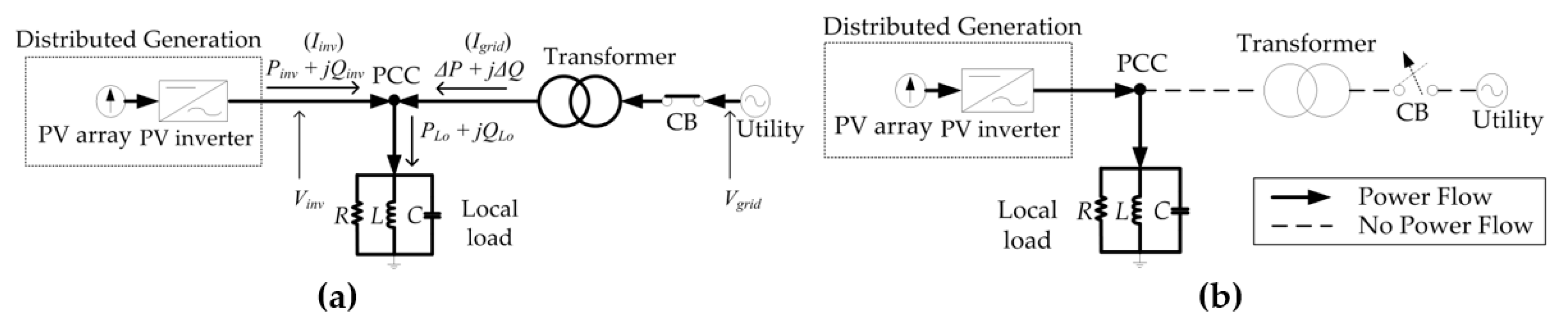
2. NDZ Comparisons
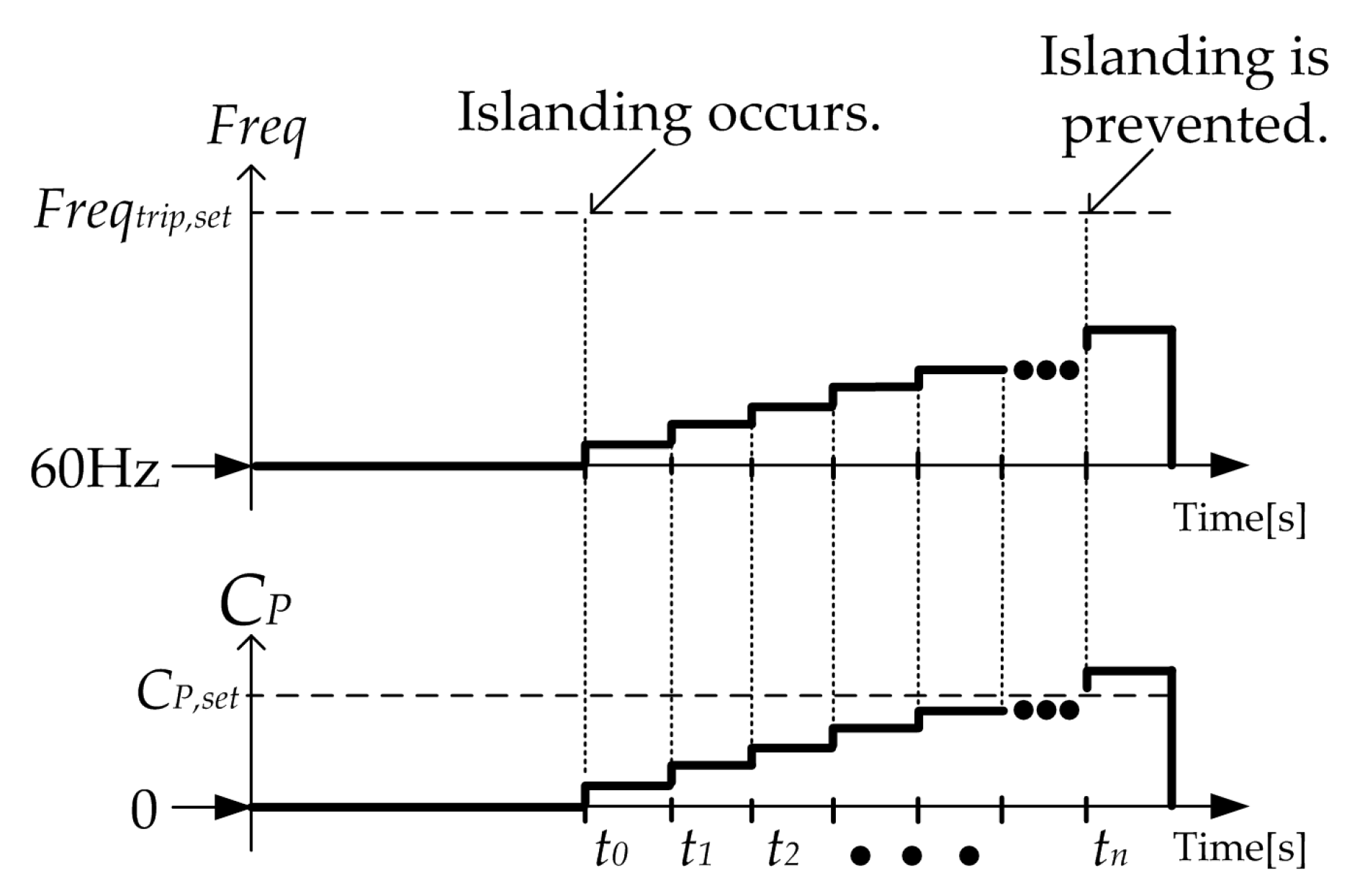
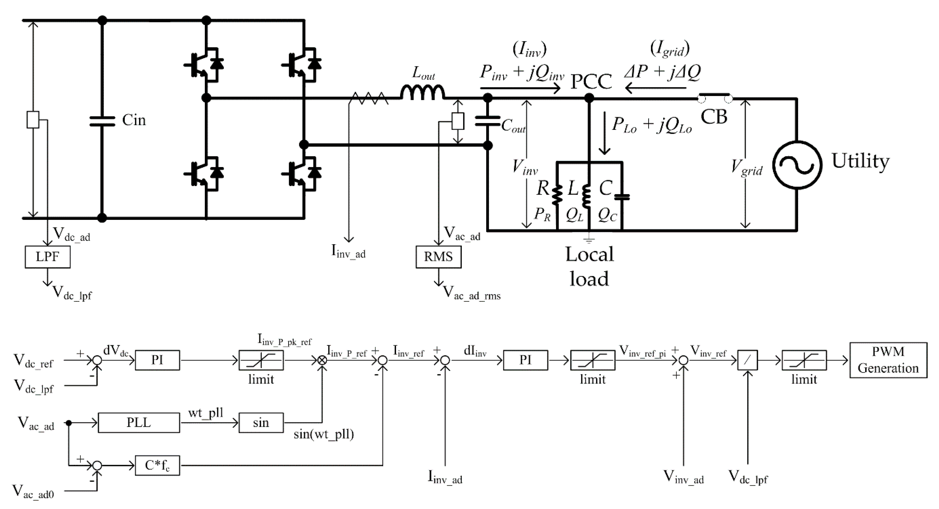
3. The Proposed AIM
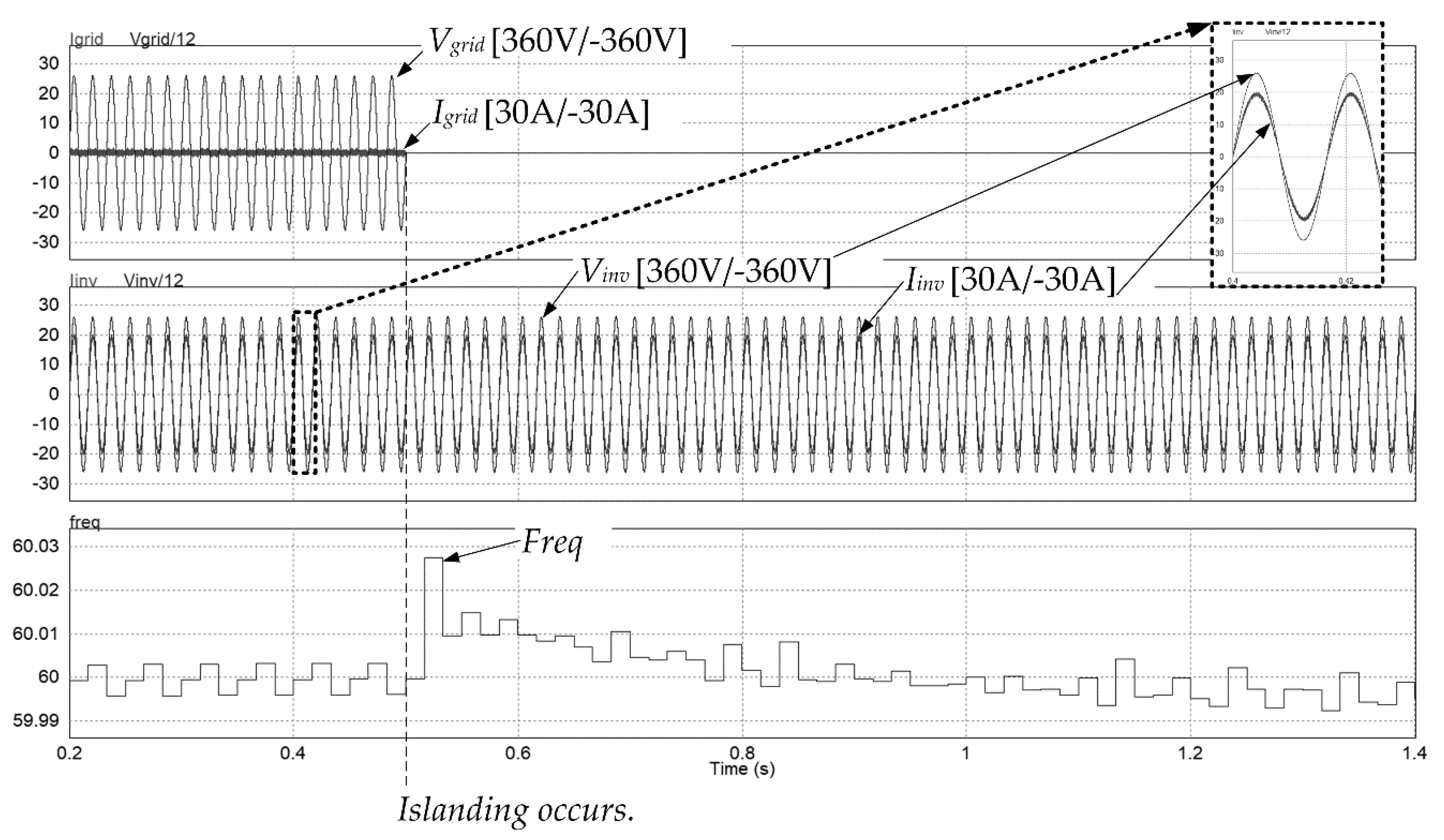
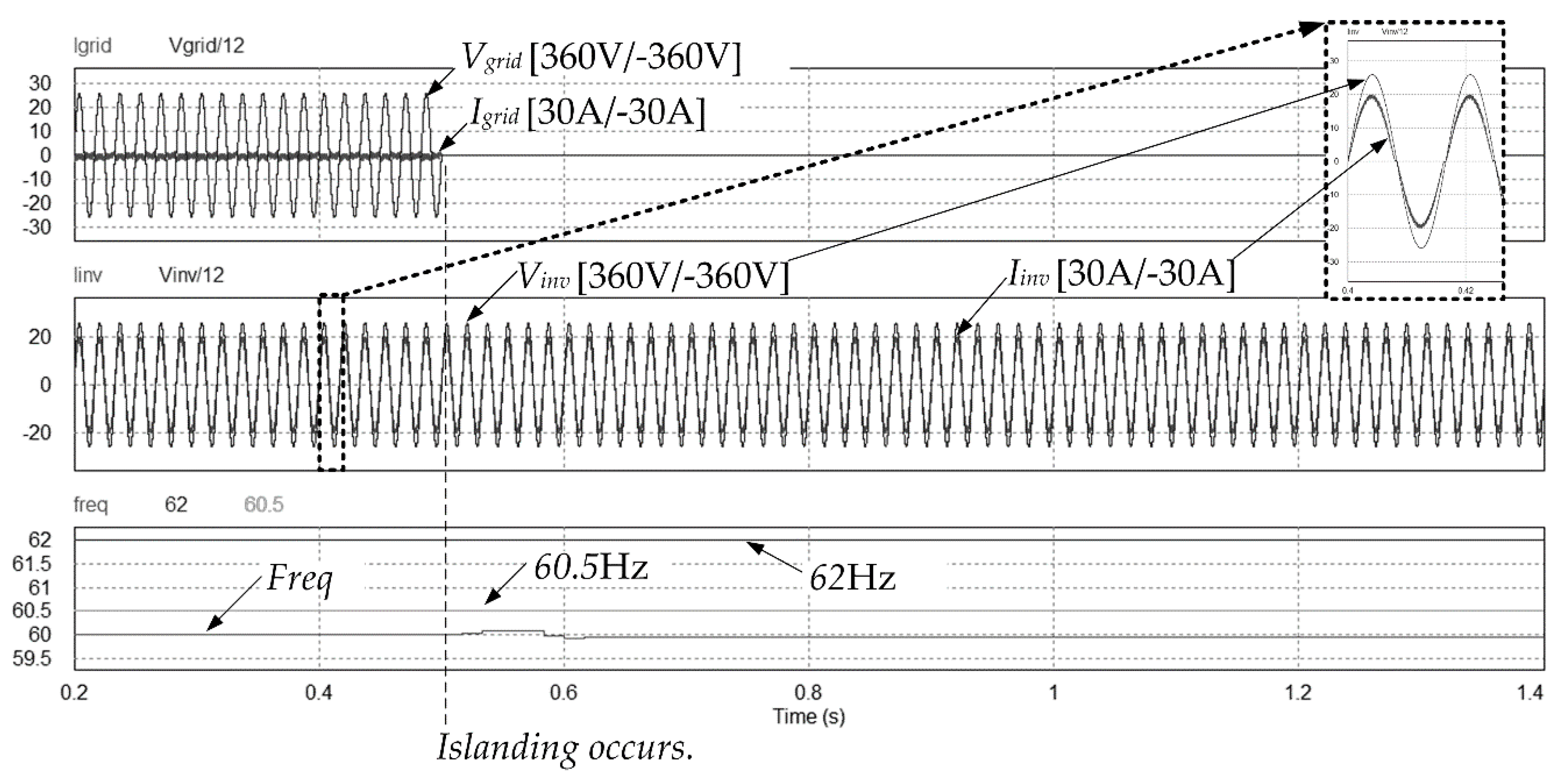
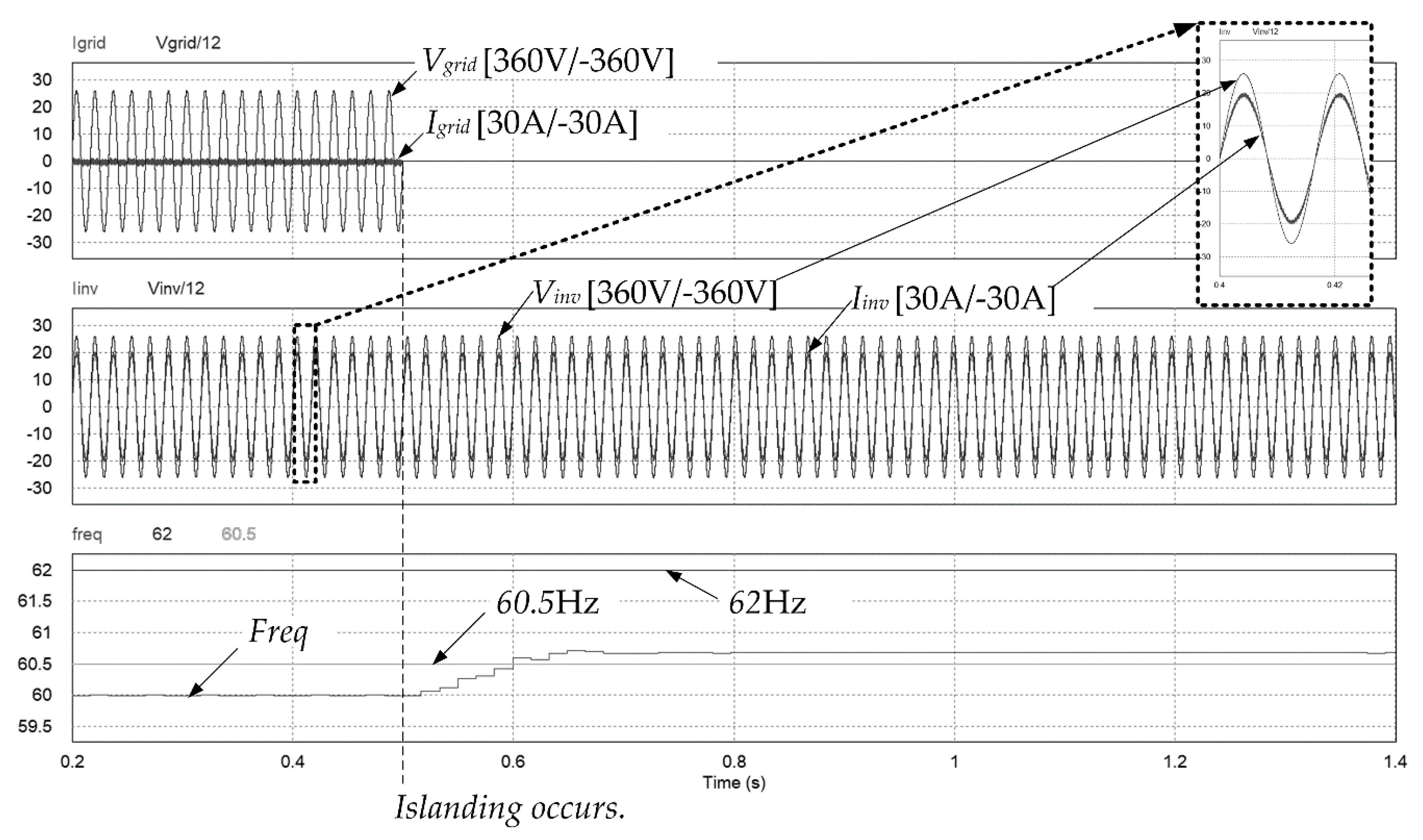
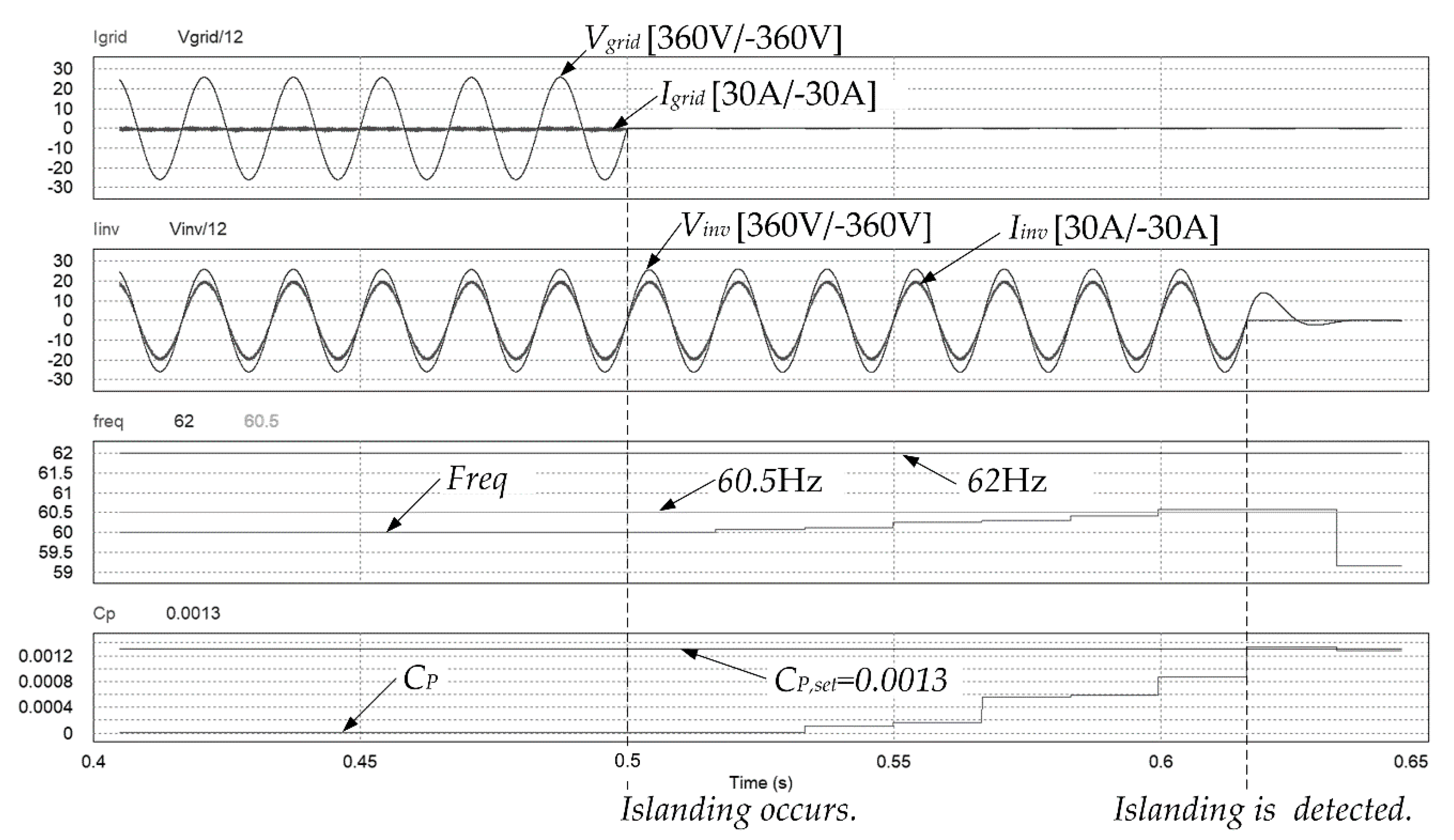
4. Simulation Results
5. Conclusions
Funding
Conflicts of Interest
References
- Chen, G.; Lewis, F.L.; Feng, E.N.; Song, Y. Distributed optimal active power control of multiple generation systems. IEEE Trans. Ind. Electron. 2015, 62, 7079–7090. [Google Scholar] [CrossRef]
- Huang, W.; Zhang, N.; Yang, J.; Wang, Y.; Kang, C. Optimal Configuration Planning of Multi-Energy Systems Considering Distributed Renewable Energy. IEEE Trans. Smart Grid 2019, 10, 1452–1464. [Google Scholar] [CrossRef]
- Cady, S.T.; Dominguez-Garcia, A.D.; Hadjicostis, C.N. A distributed generation control architecture for islanded AC microgrids. IEEE Trans. Control. Syst. Technol. 2015, 23, 1717–1735. [Google Scholar] [CrossRef]
- Tan, Y.; Wang, Z. Incorporating unbalanced operation constraints of three-phase distributed generation. IEEE Trans. Power Syst. 2019, 34, 2449–2452. [Google Scholar] [CrossRef]
- Massignan, J.A.D.; Pereira, B.R.; London, J.B.A. Load flow calculation with voltage regulators bidirectional mode and distributed generation. IEEE Trans. Power Sys. 2017, 32, 1576–1577. [Google Scholar]
- Makwana, Y.M.; Bhalja, B.R. Experimental Performance of an Islanding Detection Scheme Based on Modal Components. IEEE Trans. Smart Grid. 2019, 10, 1025–1035. [Google Scholar] [CrossRef]
- Raipala, O.; Makinen, A.S.; Jarventrausta, P. An anti-islanding protection method based on reactive power injection and ROCOF. IEEE Trans. Power Deliv. 2017, 32, 401–410. [Google Scholar] [CrossRef]
- IEEE Standard for Interconnection and Interoperability of Distributed Energy Resources with Associated Electric Power Systems Interfaces; IEEE Std. 1547–2018; IEEE Standard Association: Piscataway, NJ, USA, 2018.
- Recommended Settings for Voltage and Frequency Ride-Through of Distributed Energy Resources. EPRI Report, Product Id: 3002006203. Available online: https://www.epri.com/#/pages/product/3002006203/ (accessed on 25 April 2020).
- Pouryekta, A.; Ramachandaramurthy, V.K.; Mithulananthan, N.; Arulampalam, A. Islanding Detection and Enhancement of Microgrid Performance. IEEE Syst. J. 2018, 12, 3131–3141. [Google Scholar]
- Liu, S.; Zhuang, S.; Xu, Q.; Xiao, J. Improved voltage shift islanding detection method for multi-inverter grid-connected photovoltaic systems. IET Gener. Transm. Distrib. 2016, 10, 3163–3169. [Google Scholar] [CrossRef]
- Guha, B.; Haddad, R.J.; Kalaani, Y. Voltage ripple-based passive islanding detection technique for grid-connected photovoltaic inverters. IEEE Power Energy Technol. Syst. J. 2016, 3, 143–154. [Google Scholar] [CrossRef]
- Raza, S.; Mokhlis, H.; Arof, H.; Laghari, A.; Mohamad, H. A sensitivity analysis of different power system parameters on islanding detection. IEEE Trans. Sustain. Energy 2016, 7, 461–470. [Google Scholar] [CrossRef]
- Liu, N.; Diduch, C.; Chang, L.; Su, J. A reference impedance-based passive islanding detection method for inverter-based distributed generation system. IEEE J. Emerg. Sel. Top. Power Electron. 2015, 3, 1205–1217. [Google Scholar] [CrossRef]
- Kim, B.; Sul, S. Stability-Oriented Design of Frequency Drift Anti-Islanding and Phase-Locked Loop Under Weak Grid. IEEE J. Emerg. Sel. Top. Power Electron. 2017, 5, 760–774. [Google Scholar] [CrossRef]
- Wen, B.; Boroyevich, D.; Burgos, R.; Shen, Z.; Mattavelli, P. Impedance-Based Analysis of Active Frequency Drift Islanding Detection for Grid-Tied Inverter System. IEEE Trans. Ind. Appl. 2016, 52, 332–341. [Google Scholar] [CrossRef]
- Pourbabak, H.; Kazemi, A. Islanding detection method based on a new approach to voltage phase angle of constant power inverters. IET Gener. Transm. Dis. 2016, 10, 1190–1198. [Google Scholar] [CrossRef] [Green Version]
- Chen, X.; Li, Y. An Islanding Detection Method for Inverter-Based Distributed Generators Based on the Reactive Power Disturbance. IEEE Trans. Power Electron. 2016, 31, 3559–3574. [Google Scholar] [CrossRef]
- Khan, M.A.; Kurukuru, V.S.B.; Haque, A.; Mekhilef, S. Islanding Classification Mechanism for Grid-Connected Photovoltaic Systems. IEEE J. Emerg. Sel. Top. Power Electron. 2020. [Google Scholar] [CrossRef]
- Faqhruldin, O.N.; EL-Saadany, E.F.; Zeineldin, H.H. A universal islanding detection technique for distributed generation using pattern recognition. IEEE Trans. Smart Grid. 2014, 5, 1985–1992. [Google Scholar] [CrossRef]
- Yu, B. An Improved Active Frequency Drift Anti-Islanding Detecting Module for Multiple PV Micro-Inverter Systems and Detecting Method Using the Same; No. 10-1530207: Seoul, Korea, 2014. [Google Scholar]
- Ye, Z.; Kolwalkar, A.; Zhang, Y.; Du, P.; Walling, R. Evaluation of anti-islanding schemes based on nondetection zone concept. IEEE Trans. Power Electron. 2004, 19, 1171–1176. [Google Scholar] [CrossRef]
- Utility-Interconnected Photovoltaic Inverters-Test Procedure of Islanding Prevention Measures; IEC 62116:2014; International Electrotechnical Commission: Geneva, Switzerland, 2014.
- Ropp, M.E.; Begovic, M.; Rohatgi, A. Analysis and performance assessment of the active frequency drift method of islanding prevention. IEEE Trans. Energy Convers. 1999, 14, 810–816. [Google Scholar] [CrossRef]
- Vahedi, H.; Mehdi, K.; Gharehpetian, G.B. Accurate SFS Parameter Design Criterion for Inverter-Based Distributed Generation. IEEE Trans. Power Deliv. 2016, 31, 1050–1059. [Google Scholar] [CrossRef]
- Sun, Q.; Guerrero, J.M.; Jing, T.; Vasquez, J.C.; Yang, R. An Islanding Detection Method by Using Frequency Positive Feedback Based on FLL for Single-Phase Microgrid. IEEE Trans. Smart Grid. 2017, 8, 1821–1830. [Google Scholar] [CrossRef] [Green Version]
- Jung, Y.; Choi, J.; Yu, G. A novel active anti-islanding method for grid-connected photovoltaic inverter. J. Power Electron. 2007, 7, 64–71. [Google Scholar]
- IEEE Recommended Practice for Utility Interface of Photovoltaic (PV) Systems; IEEE Std. 929-2000; IEEE Standard Association: Piscataway, NJ, USA, 2000.


| Standard | Over Frequency [Hz] | Under Frequency [Hz] | Clearing Time | Condition | Non Detection Zone |
|---|---|---|---|---|---|
| IEEE Std. 929–2000 | 60.5 | 59.3 | 6 [cycles] | ≤ 10 [kW], Qf = 2.5 | |
| IEEE Std. 1547–2003 | 60.5 | 59.3 | 0.16 [s] | ≤ 30 [kW], Qf = 1 | |
| IEEE Std. 1547–2018 | 62.0 | 56.5 | 0.16 [s] | Default setting, Qf = 1 |
| Parameter | Value | |
|---|---|---|
| Local load R, L, C power | Quality factor Qf = 1 | PR = 3 kW QL = 3 kVar QC = 3 kVar |
| Single DG inverter nominal power, Pinv | 3 kW | |
| Threshold value of correlation parameter, CP,set | 0.0008 (when N = 5, Kp = 0.02) | |
| Frequency trip setting | OF: 62 Hz, UF: 56.5 Hz | |
| OF: 62 Hz, UF: 56.5 Hz | 56.5 < f < 62 Hz | |
| Nominal grid voltage, frequency, Vgrid | 220 V, 60 Hz single phase | |
| AIM | AFD Method (Fixed cf) | AFDPF Method (Varying cf) | The Proposed Method (Varying cf) | |||||
|---|---|---|---|---|---|---|---|---|
| Parameter | ||||||||
| cf [%] | 1 | 2 | 3 | 4 | 5 | |||
| Kp | - (No need) | 0.02 | 0.02 | |||||
| Anti-islanding detection time [s] at ΔP and ΔQ 0 | No detection | No detection | 0.116 | |||||
| THDi [%] before islanding | 3.18 | 3.19 | 3.53 | 4.10 | 5.53 | 3.18 | 3.18 | |
© 2020 by the author. Licensee MDPI, Basel, Switzerland. This article is an open access article distributed under the terms and conditions of the Creative Commons Attribution (CC BY) license (http://creativecommons.org/licenses/by/4.0/).
Share and Cite
Yu, B. Study on a Correlation-Based Anti-Islanding Method under Wider Frequency Trip Settings for Distributed Generation. Appl. Sci. 2020, 10, 3626. https://doi.org/10.3390/app10103626
Yu B. Study on a Correlation-Based Anti-Islanding Method under Wider Frequency Trip Settings for Distributed Generation. Applied Sciences. 2020; 10(10):3626. https://doi.org/10.3390/app10103626
Chicago/Turabian StyleYu, Byunggyu. 2020. "Study on a Correlation-Based Anti-Islanding Method under Wider Frequency Trip Settings for Distributed Generation" Applied Sciences 10, no. 10: 3626. https://doi.org/10.3390/app10103626
APA StyleYu, B. (2020). Study on a Correlation-Based Anti-Islanding Method under Wider Frequency Trip Settings for Distributed Generation. Applied Sciences, 10(10), 3626. https://doi.org/10.3390/app10103626