1. Introduction
Energy is an important guarantee for human social and economic development. Driven by rapid industrialization and urbanization, the energy problems are becoming increasingly acute, especially in the fields of geotherm, metallurgy, chemistry, electrical, and machinery [
1]. The consumption of primary fossil fuels and the discharge of pollutants are increasing. So, it is crucial to increase the recovery efficiency of energy sources, one of which is the waste heat from industries.
The waste heat sources are generally classified by temperature into three categories: Low-grade, medium-grade, and high-grade. The medium-grade and high-grade waste heat can be easily utilized by steam Rankine cycle or heating other streams. However, the low-grade waste heat, which accounts for half of the total, is hard to recycle. In addition, the waste heat should be condensed by cooling water or cooling air, which results in higher cost.
Compared with the ordinary steam Rankine cycle, the organic rankine cycle (ORC) replaces the working fluid with an organic medium with a lower boiling point, which could make use of the low-grade heat. That heat is then used to create organic vapor, which in turn drives an expander to generate electricity. The types of energy available for the ORC energy recovery system includes internal combustion engine waste heat [
2,
3], industrial waste heat [
4], solar energy [
5], biomass [
6,
7], water desalination [
8], and geothermal energy [
9]. The usage of ORC for low-temperature waste heat recovery has many advantages such as: Simple mechanical structure, low pressure, convenient maintenance, remarkable economic benefit, and high recovery efficiency. Therefore, ORC is one of the hot topics in the field of low temperature waste heat recovery.
The ORC system is more suitable for recovering waste heat from low and medium temperatures resources. However, the thermal efficiency of the cycle is still low. It is still a challenge to improve the thermodynamic performance of the ORC system. Secondly, due to the high investment in generating units, it is often necessary to rely on economies of scale to have better economic value [
10]. Previous research has found that it is important to improve cycle performance, select a working fluid, and determine the best operating parameters. Arabkoohsar et al. [
11] modified a hybrid waste-driven CHP-ORC plant with exhaust heat recovery using the flue gas condensation loop. Which led to an efficiency enhancement compared to its primary design.
Mahmoudi et al. [
12] propose the most influential thermo-physical characteristics of working fluids were critical state, sensible heat and ratio of vaporization latent heat. They believe the mixing of different working fluids is an effective way to improve these thermo-physical properties. Mixed fluids compared to pure fluids have shown better performance on average but their compositions and mass fractions heavily change the cycle performance, and should be optimized in the design process of ORC plants. Xi et al. [
13] analyzed the sensitivity of operation parameters on the system performance of ORC system using orthogonal experiment, which shows that the temperature at the inlet of the expander is the most significant factors for the system performances.
As for the application of ORC in chemical industry, Song et al. [
14] analyzed and optimized a comprehensive ORC recovery system utilizing five waste heat sources distributed in different temperature levels, from a 1.2 million ton-level reforming and extraction unit in Shijiazhuang Refining & Chemical Company of China. Four schemes are presented in continuous optimization progress with the aim of simplifying the entire system and achieving both the robust thermal performance and economic benefit. More parametric optimization of the ORC was studied by researchers around the world. Sun et al. [
15] established a mathematical model of low-temperature ORC system, and investigated several factors influencing the exergy efficiency.
Many researchers have done a lot of research on the working fluid of ORC systems. Kajurek et al. [
16] examined ten different working fluid in terms of the thermal efficiency for a modified ORC. They found ammonia (R717), which is characterized by both the highest specific volume of saturated vapor flowing into the tanks and the largest difference between working pressures, obtained the maximum efficiency. Also, a mixture of ammonia and water has always been used in the Kalina Cycle, which has been investigated as a competitor of ORC, to recover the waste heat [
17]. Van Kleef et al. [
18] developed a thermo-economic CAMD-ORC framework and applied to subcritical and non-recuperated ORC systems in waste-heat recovery applications represented by a range of heat-source temperatures from 150 °C to 350 °C. Gyorke et al. [
19] established a new working fluid classification method based on the existence and relative location of some characteristic points of the vapor–liquid coexistence curve in T-s diagram. Sadeghi et al. [
20] performed thermodynamic modeling and multi-objective optimization for three different configurations of the ORC running by ten zeotropic mixtures and one pure refrigerant as the working fluid. They found using zeotropic mixtures as the working fluid instead of a pure fluid such as R245fa could generate more power.
In China Shenhua’s 1.8 million tons MTO process, a large amount of low-temperature energy has not been fully utilized. This part of the energy comes from the water washing tower and the quench tower. The water temperature of the quench tower is 110 °C, and the water temperature of the water washing tower is 95 °C [
21]. At present, the low temperature energy of this part is mainly used for energy supply of the reboiler of the subsequent olefin separation unit. From the first law of thermodynamics, about 60% of low-grade energy cannot be recovered. From the perspective of the second law of thermodynamics, the low-grade energy is degraded while the heat source (about 100 °C) is used to heat the reboilers (about 50 °C). Therefore, it can be seen that this part of the energy has not been used reasonably from the perspective of the first law of thermodynamics and the second law of thermodynamics.
In the recent research on the recovery of low-temperature waste heat by the ORC system, the heat sources are often considered as single stream, and most of them are directly condensed by cooling water or cooling air. In the MTO process, there is a heat source of multiple streams, and part of the energy is used by subsequent unit operations (distillation units). Therefore, a new energy utilization process needs to be designed, so that when the energy demand of the process meet itself, more low-temperature energy could be recovered.
This paper is based on the current energy utilization status of the MTO process, and introduces the ORC energy recovery technology into the energy recovery in MTO process. According to the above literature, there is currently no ORC energy recovery for the low temperature waste heat of the MTO process. And less research on the overall optimization of ORC energy recovery schemes for multi-stream heat sources. In order to make up for the shortcomings in the literature, this paper first proposes five ORC energy recovery design schemes for multi-stream low-temperature heat sources while ensuring the energy supply of the energy-demanding unit. Then, parameters optimization and working fluid screening are performed for each scheme. Finally, the mixed working fluid was introduced to explore the effect of mixed working fluid on the thermal efficiency of ORC system.
3. Results and Discussion
This section provides five combined heat network models to use the waste heat to achieve higher power generation while ensuring the original energy supply demand, as well the higher expander output work. The output work of the expander is mainly determined by three parameters: The flow rate of the circulating working fluid, the inlet pressure of the expander, and the outlet pressure of the expander.
According to the description in the previous section, the flow rate in this paper is not studied as an independent parameter while it changes with other parameters. The inlet pressure of the expander is the saturated vapor pressure of the circulating working fluid at the evaporation temperature, and the outlet pressure is the saturated vapor pressure of the circulating working fluid at the condensing temperature. Under the condition that the duty of the heat source is fixed, the inlet temperature of the expander is positively correlated with the flow rate, as well the inlet pressure. When the inlet pressure of the expander is determined, the output work of the expander is negatively correlated with the output pressure.
The evaporation temperature is limited by the temperature of the heat source, and the condensation temperature is limited by the temperature of the coolant. For the condensation temperature, the hydrocarbons in the reboilers of the olefin separation section in the MTO process can be used as the coolant, and the cooling water (35 °C) can also be used as the coolant which depends on the arrangement of the heat exchanger networks.
According to the heat load and temperature level of each reboiler in the
Table 1 and
Table 2, The main division is based on the energy of the reboilers of the propylene columns, which consume the most energy in the subsequent olefin separation units. The reboiler temperatures are 52 °C and 46.5 °C, respectively. According to this situation, there are three options for the condensation temperature of the condenser.
High condensation temperature is 57 °C. By the time, the reboilers of the propylene towers are completely heated by the exhaust steam.
The medium condensation temperature is 51.5 °C. Now the reboiler of the propylene tower #2 is heated by the exhaust steam, and the reboiler of the propylene tower #1 is heated by the wash water.
The low condensation temperature is 45 °C. At the moment, all of the reboilers of the propylene towers are heated by the waste heat of wash water and quench water.
After satisfying the thermal load of the two propylene columns, a suitable stream is selected to heat the remaining two reboilers. It can be divided into two cases according to different working conditions. The first case is to maintain the original heating position, and the other is to use branch streams to meet the thermal load. Based on the statements above, this paper carries out a thermodynamic analysis about the ORC system, and five schemes of the ORC system are proposed to pursuit the maximum output power and maximum exergy efficiency.
3.1. Thermodynamic Analysis of ORC System
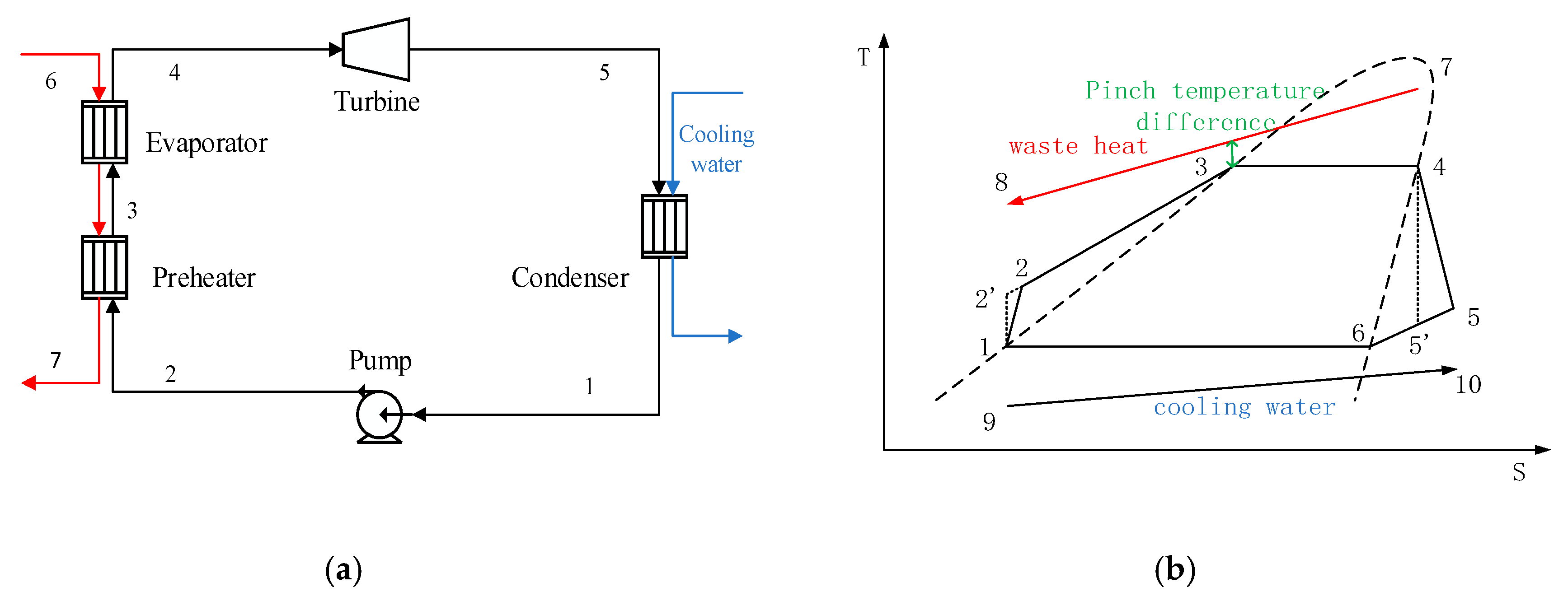
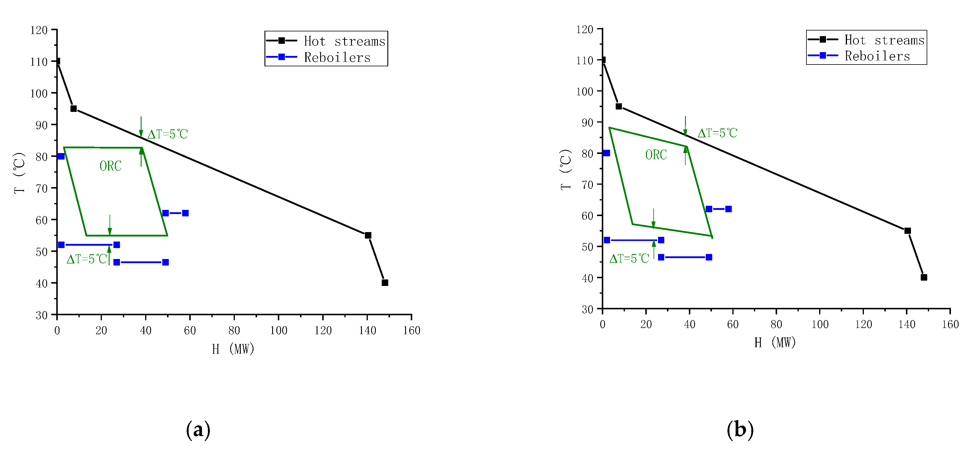
The operating condition at a high condensation temperature of 57 °C is considered as an example to perform a thermodynamic analysis of the ORC system. The heat exchanger networks are that two heat source streams heat the ethane tower reboiler and the low-pressure propane tower reboiler, and the exhaust steam at the expander outlet heats the reboilers of the two propylene towers. This paper investigates the performance of seven pure working fluid. After screening the pure working fluid, the working fluid can be ranked according to the thermodynamic performance under each working condition. Then, the optimal working fluid is chosen to form a binary mixture with each inferior working fluid, respectively. The mass fraction of the optimal working fluid and the non-optimal working fluid are both 50%. The temperature–enthalpy diagrams (T–H diagram) of this working condition are shown in
Figure 3. The two diagrams in
Figure 3 show the cold and hot streams in the MTO process and ORC system when pure and mixed working fluid are used.
From the figures we can clearly see the location of the pinch. By comparing the two figures, we can find the temperature slip caused by the mixed working fluid. This temperature slip is shown at the green line in
Figure 3b. At this time, the enthalpy line of the ORC system is closer to the enthalpy line of the heat source, so it can bring higher exergy efficiency. The position of the temperature and enthalpy line of the stream in the reboilers reflects which stream they exchange heat with.
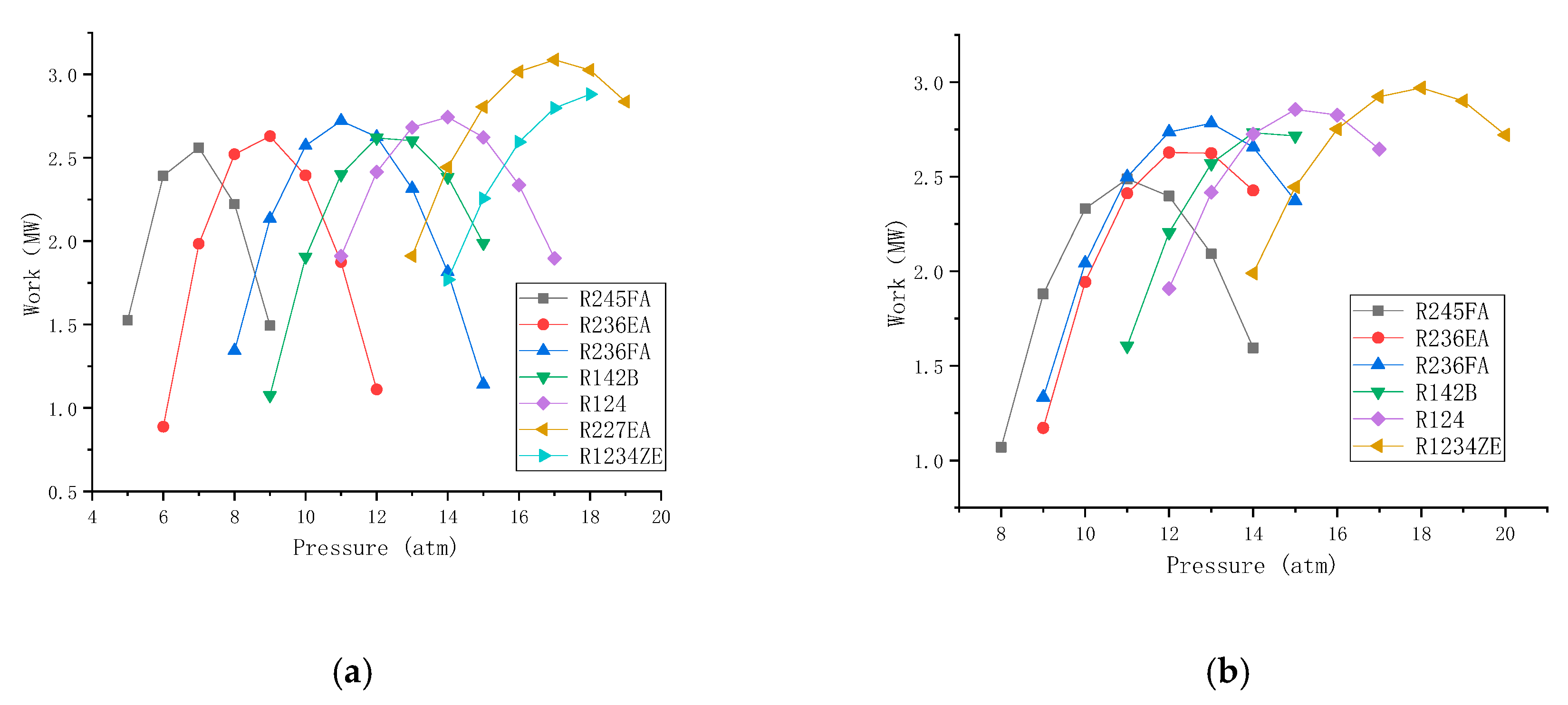
It is shown from
Figure 4 that the output power of the expander varies with the outlet pressure of the evaporator (expander outlet pressure) with pure working fluids and mixed working fluids under its operating condition. From the figure we could find that there is an optimal value (maximum value) of the output work. Because of the increase of the outlet pressure of the evaporator, the temperature is also increasing, and the working fluid flow will be reduced accordingly. Now there are two different effects on the output work: The inlet pressure has a positive effect on the output work, while the flow rate of the working fluid has a negative effect the output work. As a result of two opposite effects, the optimal value of the output work appears and so does its corresponding optimal pressure and optimal working fluid. The optimal output work in the following sections is calculated in this method.
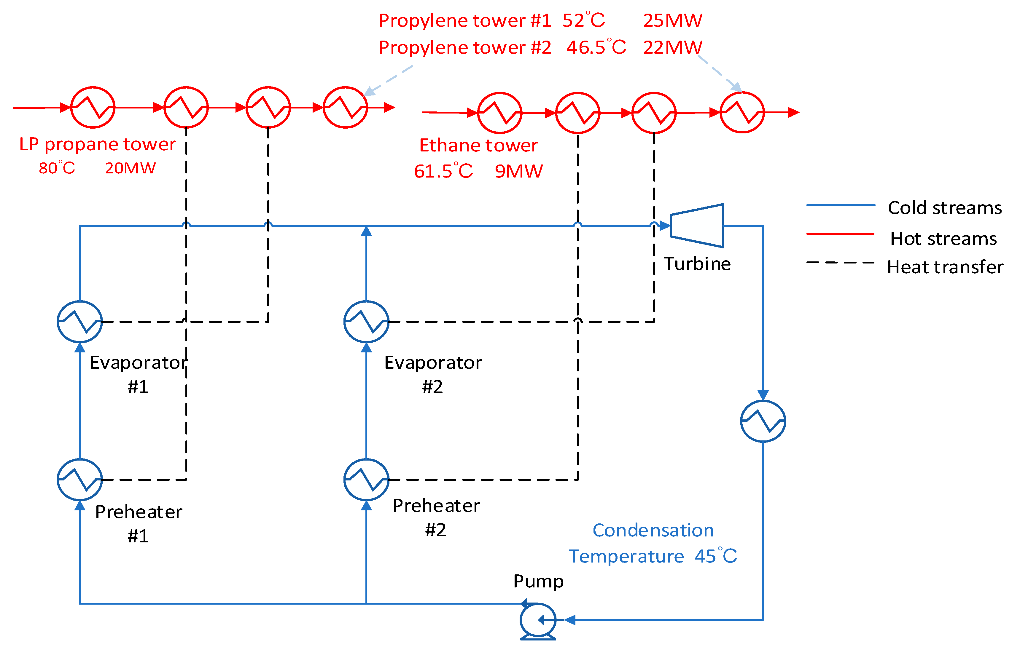
3.2. High Condensation Temperature
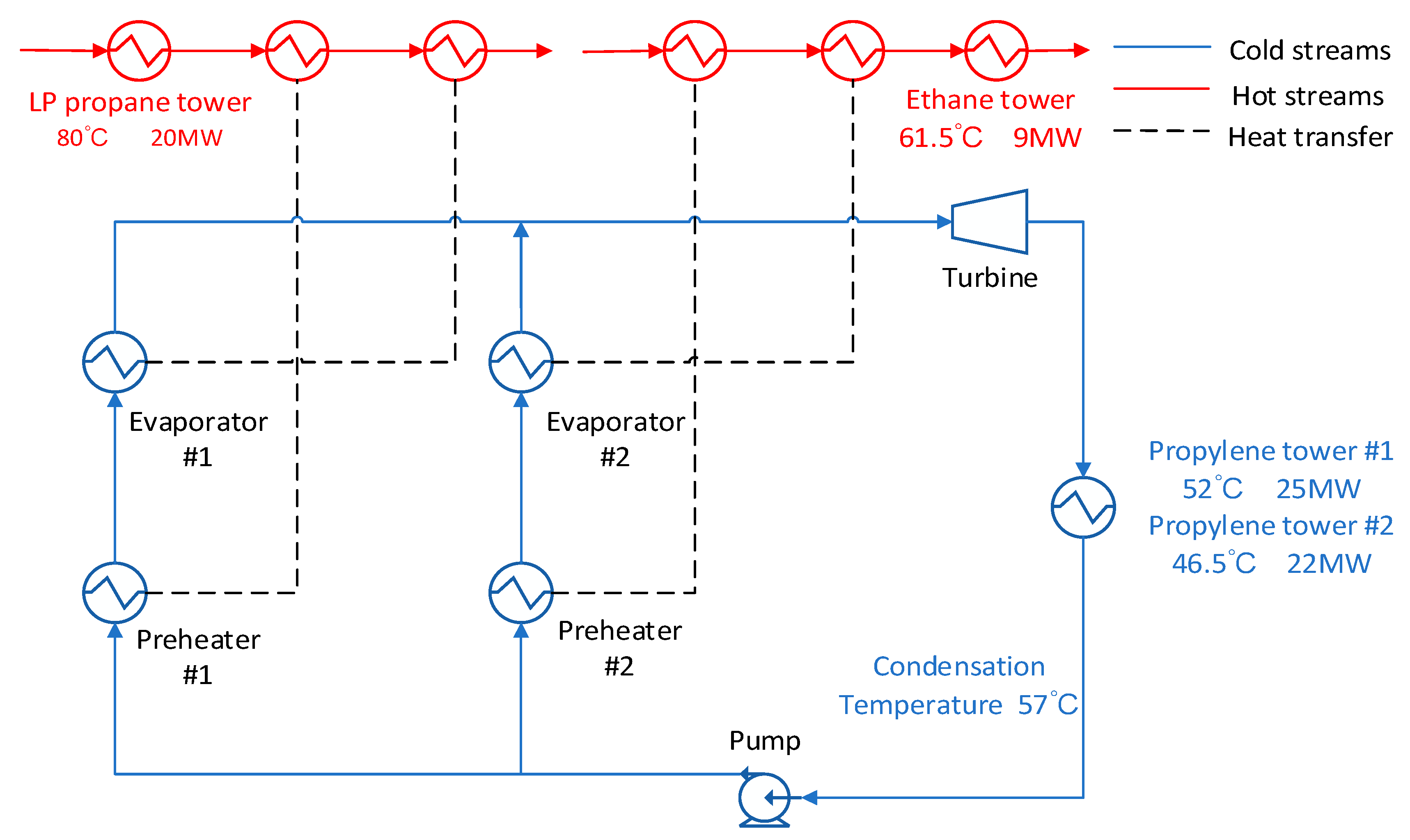
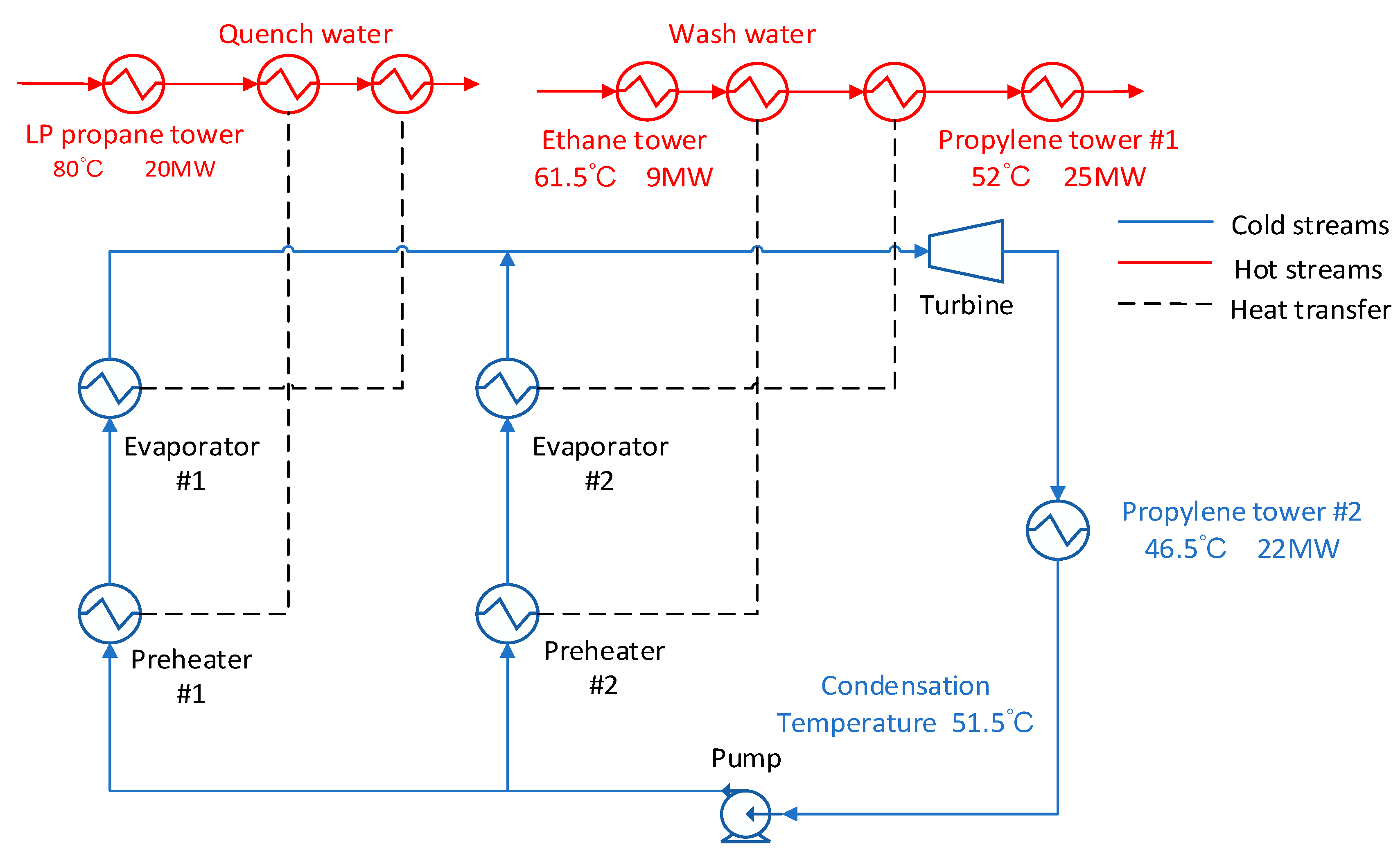
For the condensing temperature set at 57 °C, the waste heat stream at the outlet of the condenser can be used to provide energy for the propylene separation columns. As shown in
Figure 5, the energy of the low-pressure propane column and the ethane column is directly exchanged with the original heat stream without passing through the ORC system.
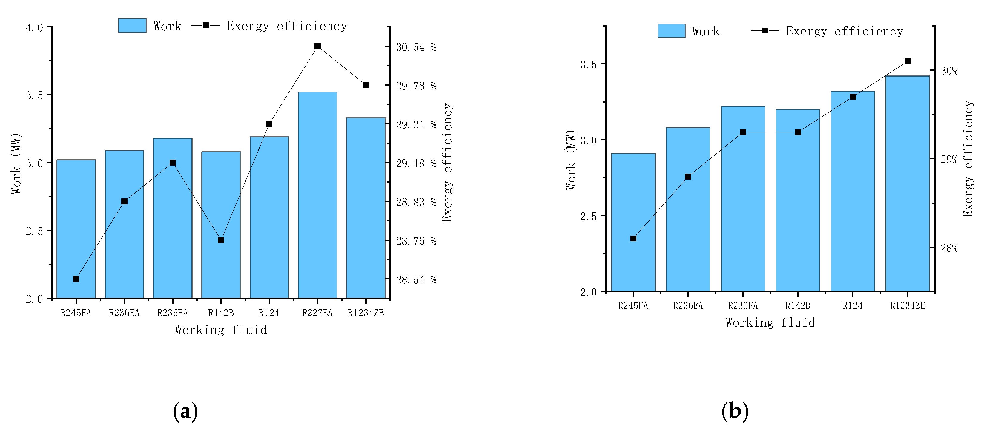
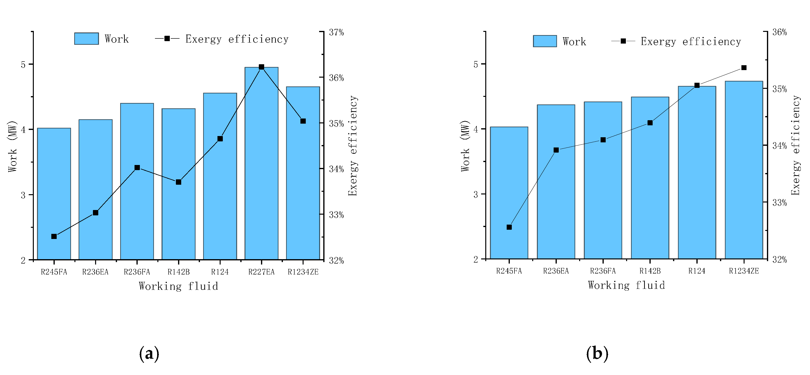
The advantage of this method is that the temperature of the hot stream which is supposed to heat the evaporator is relatively high, which cause the inlet pressure of the expander to rise. The disadvantage of this scheme is that corresponding to high expander outlet pressures at high condensing temperatures. As a result, the net output work is reduced. From
Figure 6 we could find that the maximum output work and exergy maximum efficiency varies from each working fluid. It can be found that the R227EA working fluid can obtain the maximum output work and the maximum exergy efficiency while the mixed working fluid does not show better results.
3.3. Medium Condensation Temperature
In this scheme, the condensing temperature is set at 51.5 °C. As shown in
Figure 7, the exhaust steam can only be used to heat propylene column #1 with the remaining energy of the hot stream. So, the ethane tower reboiler can only be posed at the upstream of the quench water, which limits the inlet temperature and pressure of the expander. From
Figure 8, the R227EA working fluid also obtain the maximum output work and the maximum exergy efficiency.
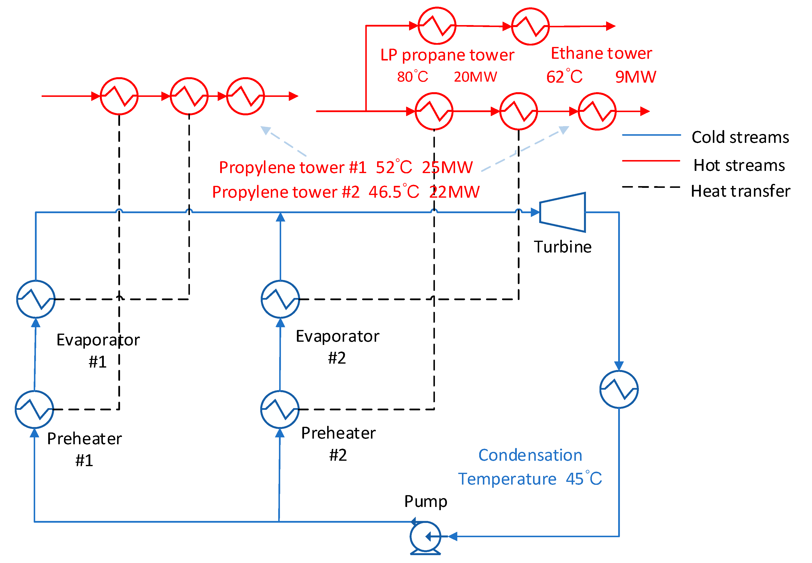
3.4. Medium Condensation Temperature with Branch Stream
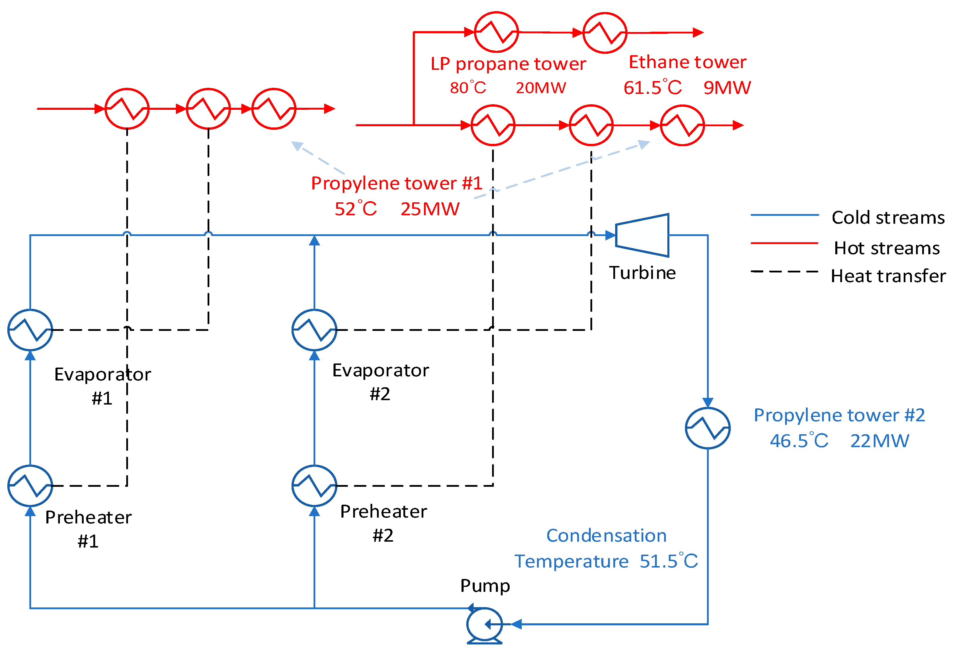
As shown in
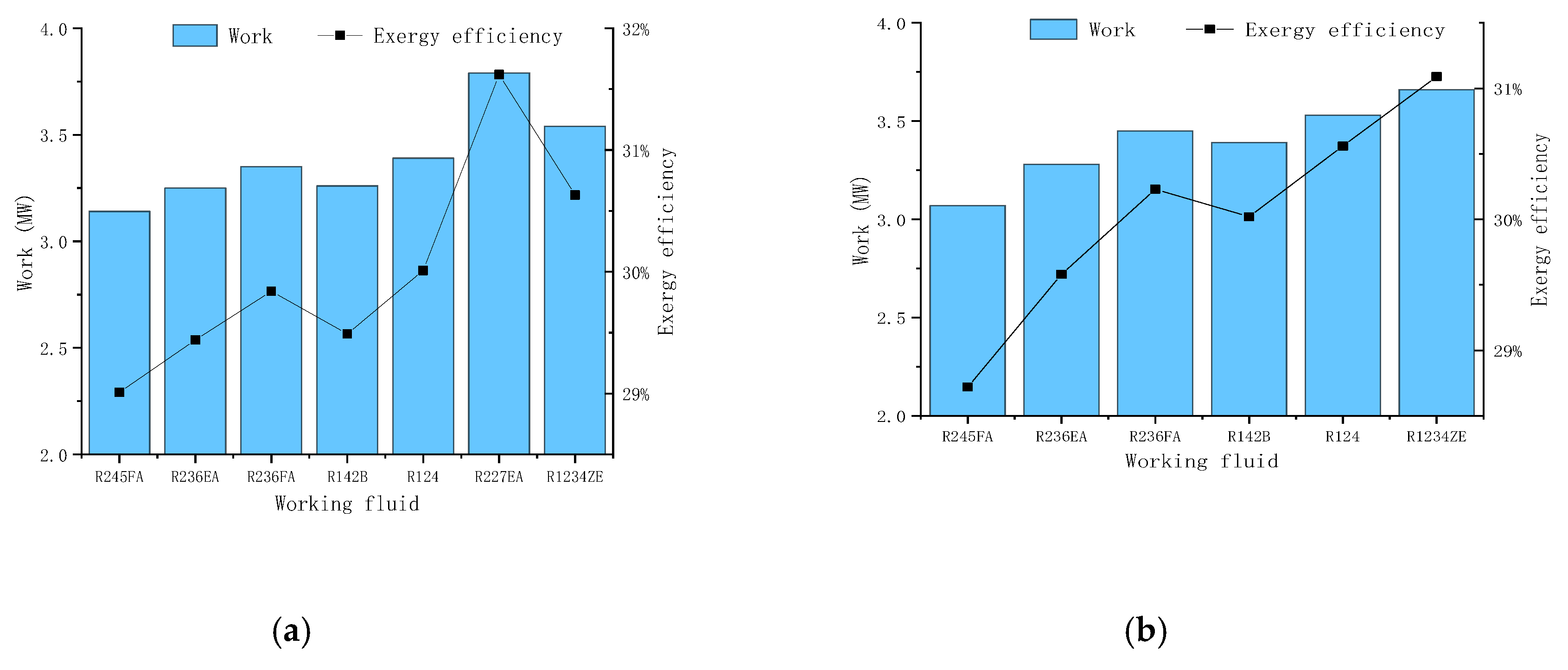
Figure 9, the washing water stream is divided next, and the low-pressure propane reboiler and the ethane tower reboiler are heated in parallel. The use of parallel streams can increase the inlet temperature and pressure of the expander. The disadvantage is that a part of the heat of the heat stream is lost. From
Figure 10 we could find in this scheme the R227EA working fluid also obtain the maximum output work and the maximum exergy efficiency.
3.5. Low Condensation Temperature
In
Figure 11, the condensation temperature is set as 45 ℃. In this scheme, it is necessary to completely use the waste heat of the high temperature stream to heat the reboilers of the two propylene towers, and when adjusting the parameters, care must be taken to make the remaining energy of the quench water and the washing water greater than the energy of the reboiler (this program has less flexibility in operation). In
Figure 12, the results show that R227EA working fluid obtain the maximum output work and the maximum exergy efficiency compared with other working fluids and mixed working fluids.
3.6. Low Condensation Temperature with Branch Stream
In this scheme, which is shown in
Figure 13, the exhaust steam at the expander outlet directly exchanges heat with the cooling water. In the wash water stream, a branch is divided to heat the ethane column reboiler and the low-pressure propane column reboiler. At this time, the propylene tower reboiler is simultaneously responsible for two heat source streams. At this time, new control conditions need to be added so that the two heat streams still have sufficient energy and temperature to meet the energy supply of the propylene tower after passing through the ORC system. From
Figure 14 we could find in this scheme the R227EA working fluid also obtain the maximum output work and the maximum exergy efficiency compared with other working fluids and mixed working fluids.
Table 3 shows the comparison between different schemes. From the table, we can see that the scheme 4 gives out the maximum output power and maximum exergy efficiency, and the best working fluid is pure R227EA. The maximum output power is 4.95MW, and the maximum efficiency is 36.2%. Besides, for all working conditions, the ORC system obtains the maximum output power and maximum efficiency when the working fluid is R227EA, which also shows that the working fluid can obtain better results at this temperature level.
4. Conclusions
This paper analyzes and optimizes a comprehensive ORC recovery system utilizing two waste heat sources distributing in different temperature levels, from a 1.8 million ton-level MTO process. Five schemes are presented in continuous optimization progress with the aim of simplifying the entire system and achieving both the maximum thermal performance and exergy efficiency. The main conclusions are summarized as follows.
The scheme of five independent subsystems is easy to design but it is difficult to handle in operation as the entire system is extremely large and complex. The maximum net power output is 4950 kW and the exergy efficiency are 36.2%. The scheme of the ORC system which the condensation temperature is 45 °C gives out the best output power.
A comparison is made between mixed working fluid and pure working fluid. It is found that although mixed working fluid can bring about temperature slip phenomenon, it does not have a beneficial effect on the system.
Thermal performance is the most important criterion for waste heat recovery system, and the system simplicity and technological feasibility as well as the economic factors still should be concerned for practical application. The analytical method and optimization progress proposed in this paper can be applied in similar recovery system for multiple stream waste heat sources.


