Article

Model Reference Adaptive Control of Vehicle Slip Ratio Based on Speed Tracking

1
School of Control Science and Engineering, Dalian University of Technology, Dalian 116023, China
2
College of Electromechanical Engineering, Dalian Minzu University, Dalian 116600, China
3
State Key Laboratory of Synthetical Automation for Process Industry, Northeastern University, Shenyang 110004, China
*
Author to whom correspondence should be addressed.
Appl. Sci. 2020, 10(10), 3459; https://doi.org/10.3390/app10103459
Submission received: 13 April 2020 / Revised: 7 May 2020 / Accepted: 15 May 2020 / Published: 17 May 2020

Abstract

This paper investigates a slip ratio control problem of a vehicle braking system in which real-time road conditions are unavailable. To overcome the nonlinearity and uncertainties, the slip ratio control problem is converted to a speed tracking control problem. By introducing a road-condition observer, a model reference adaptive control (MRAC) method is proposed to overcome modeling errors and system uncertainties. The road condition observer based on the Lyapunov theory is designed and a sliding mode observer is also constructed to estimate the unknown vehicle velocity. The asymptotic and robustness property of the adaptive controller is derived by the Popov hyperstability theory. Simulations under different conditions including different road adhesion coefficient, system uncertainties and modeling errors are provided to illustrate the effectiveness and robustness of the proposed method.

1. Introduction

Vehicle braking control is important for driving safety because it can shorten braking distance and avoid losing steering ability and vehicle instability. The braking force is directly dependent on road conditions, which, in turn, influence the wheel slip ratio [1,2]. Wheel slip ratio, the difference between vehicle longitudinal speed and wheel linear speed, should be controlled at an optimum level, so that the road–surface friction can be utilized to the maximum extent and the wheels can be prevented from locking even on a slippery road. Slip ratio control is an effective method for vehicle braking control, and it is also the core technology associated with anti-lock braking system (ABS) [3,4,5].
Slip ratio control usually requires a faster response. Modern electric vehicles or some vehicle brake systems can utilize motors or electromechanical actuators to obtain faster and more precise torque control. In addition, the uncertainty and time variability of the slip control system, especially for real-time road conditions, bring difficulties to control methodologies. Look-up tables based on experimental data are employed in most current vehicles, but their adaptability and robustness are not desirable. Many efforts have been attempted from two aspects to improve the performance. One is the model-free method, such as sliding mode control (SMC) [6,7,8], fuzzy logic control (FLC) [9,10], iterative learning control [11], etc, all of which have strong robustness but with a compromise between performance and complexity. The other is the model-based control method which is relatively simple and has requires a modest time to design and tune [12,13,14]. In [13], feedback linearization in combination with the gain scheduling-based Lyapunov approach was used and eliminated the static uncertainty using integral action and dynamic uncertainty with a sufficient stability margin. However, modeling errors still exist, the stability analysis is valid only locally and the vehicle speed is assumed as a slow time-varying parameter. In [14], a backstepping dynamic surface controller based on the Lyapunov function is designed to regulate wheel slip. It is a simple method but the adopted tire model is difficult to satisfy the varying road conditions. Some road condition estimation methods are proposed, such as a combination of stiffness-based estimation and least squares, a combination of nonlinear Lipschitz observer and modified super-twisting algorithm [15,16]. However, those methods are more complex or they require more complicated models. In [17], a simple nonlinear disturbance observer combined with a controller is used to track control, but it is based on the assumption that the observer dynamics are much faster than the disturbance.
The motivation of this study is to propose a model-based control method for slip control with enhanced braking performance and robustness. Motivated by the literature [17], a simple road adhesion coefficient observer is designed. In contrast, the observer in this paper is simpler in that its design does not require a combination controller and it does not rely on assumptions. In addition, combining the model reference adaptive controller’s strong robustness for system nonlinearity and uncertainty [18,19,20], a model reference adaptive controller based on a road condition observer is proposed in this paper. The control problem is first formulated from the speed tracking control. The asymptotic and robustness properties are obtained through the adaptive controller based on the Popov hyperstability theory, and a sliding mode observer is constructed to estimate the unknown vehicle velocity. Simulations under different conditions, including different road adhesion coefficient, system uncertainties and modeling errors, are carried out to verify the effectiveness.
The paper is organized as follows: in Section 2 the system model and control problem are formulated. Then, a model reference adaptive control strategy-based road adhesion coefficient observer is proposed in Section 3. Section 4 verifies the control algorithm through simulation researches. Finally, conclusions are given in Section 5.

2. Problem Formulation

2.1. Vehicle Slip Ratio Model

In this section, a quarter vehicle model involving the longitudinal vehicle speed dynamics and the wheel rotational dynamics represents the vehicle fundamental longitudinal dynamics [11,21]. As shown in Figure 1, the model is obtained from single-wheel vehicle dynamics attached to a mass m . The braking force F d is
F d = μ ( λ ) m g
where, λ is the longitudinal slip ratio, μ is the road adhesion coefficient, m is the mass of the vehicle supported by the wheel.
Obviously, braking force F d depends on the road adhesion coefficient μ which is a nonlinear function of the longitudinal slip ratio λ . Among the uncertainties, the road condition is one of the most complicated variables, which is difficult to be measured in real time but affects the control performance directly. Some researches [22,23,24] adopted empirically parameterized tire models to represent the relationship, such as the Magic Tire Formula [25], the Burckhardt [26,27,28] and the LuGre [27]. However, it is difficult to describe the varying road conditions accurately, which is the research focus of this study.
Considering longitudinal velocity and angular velocity of the wheel as the degrees of freedom during the braking process, the wheel nonlinear dynamic can be described [21]:
n w m d v d t = n w μ ( λ ) m g c v v 2
J w d ω w d t = T b r w ( μ ( λ ) m g + f w )
where, f w = c f ω w denotes the various rolling friction forces and c f is the friction coefficient, r w is the wheel radius, J w is the wheel inertia, n w is the number of wheels, c v is the air resistance coefficient.
The longitudinal slip ratio [21] is defined as follows
λ = v w v max ( v , v w )
where v w = ω w r w . It describes the normalized difference between the vehicle speed and the speed of the wheel perimeter. If λ = 0 , the wheel is free motion and v w = v . while λ = 1 means that the wheel is locked. The relationship of the typical road adhesion coefficient with the wheel slip developed by Burckhardt model is shown in Figure 2 [28,29].
It can be seen that the slip ratio is different on the different road conditions and the difference between the vehicle speed and the speed of the wheel varies with the conditions too. However, the optimal slip ratio is controlled within a certain scope, which is considered as stable regions. Thus, the desired value can be set in the range or a desired slip ratio trajectory. The control problem is to regulate the slip ratio in accordance with the desired slip ratio and can be solved from the point of view of speed tracking v w = ( 1 + λ * ) v .
Remark 1.
For the situation of vehicle longitudinal slip ratio control, the braking torque is controlled according to the wheel that first appears braking lock or the road surface with low adhesion coefficient. Therefore, a quarter vehicle model involving the longitudinal vehicle speed dynamics is available for research and it can be further extended to more complex mechanical structures, e.g., full-wheel-drive vehicles. Of course, during the turning process, the lateral vehicle speed, yaw rate, and the lateral slip ratio should be considered which will be the next research.

2.2. Problem Formulations

The control of braking force is mainly determined by the road adhesion coefficient, while the road adhesion coefficient is also a function of the slip ratio. Therefore, the target of the control system is to maintain the slip ratio around the desired λ ( t ) . From the definition of slip ratio, the optimal braking force can be obtained when v w = ( 1 + λ * ) v . Accordingly, the control problem can be solved from the point view of vehicle speed tracking and the wheel speed can be controlled through the braking torque in (3). The wheel speed dynamic (3) is re-described as:
{ d v w d t = b 1 v w + b 2 T b + b 3 μ ( λ ) v w = ω w r w
where, b 1 = c f r w J w , b 2 = r w J w , b 3 = r w 2 m g J w , ω w is the system state, T b is the control input, v w is the controlled output which can be measured by wheel speed sensors, and μ ( λ ) is an unknown and uncertainty term.
The vehicle speed dynamic (2) is rewritten as
d v d t = a 1 v 2 + a 2 μ ( λ )
where, a 1 = c v n w m , a 2 = g .
To sum up, the control problem is to find the optimal braking torque T b , for the system (5), to realize the vehicle speed tracking control so that the desired slip ratio can be well tracked.

3. Model Reference Adaptive Control for Slip Ratio Control

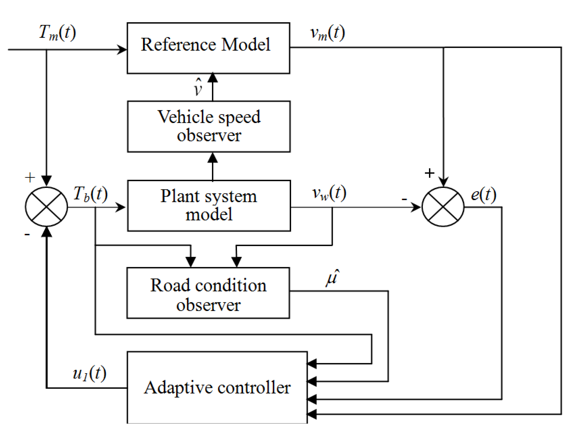
In this section, a model reference adaptive controller based on a road condition observer is designed to facilitate vehicle speed tracking control. The control system diagram is shown in Figure 3. The basic idea of the model reference adaptive controller is to design an adaptive control law so that the tracking error between the reference model and the plant asymptotically converges to zero by automatically adjusting the adaptive parameters. The reference model is obtained by a vehicle speed observer. Based on the road condition observer, the model reference adaptive controller has stronger anti-disturbance capability and adaptability.

3.1. Model Reference Adaptive Controller

The plant model (5) is described in the form of a differential operator:
p v w = b 1 v w + b 2 T b + b 3 μ ( λ ) ( p b 1 ) v w = b 2 T b + b 3 μ ( λ ) A p ( p ) v w ( t ) = b p T b + b 3 μ ( λ )
where, A p = p b 1 , b p = b 2 , and p = d d t is the differential operator.
The chosen reference model is defined as (8), in which the desired output is v m ( t ) = v ^ ( t ) ( 1 + λ * ) , and v ^ is estimated by vehicle velocity observer.
A m v m ( t ) = b m T m ( t )
where b m is a positive gain, A m = p + a 0 , a 0 is a given constant determined by a performance index requirement, T m ( t ) is the control input of the reference model which represents the basic value of braking torque. The tracking error is defined as
e ( t ) = v m ( t ) v w ( t )
The generalized error equation and model reference adaptive adaptation law are derived as follows.
The relationship of braking torque T b ( t ) , the control input of the reference model T m ( t ) and the output of the adaptive controller u 1 ( t ) is constructed as
T b ( t ) = T m ( t ) u 1 ( t )
Subtracting (7) from (8), and adding A p v m ( t ) to both sides of the equation results in:
A m v m ( t ) A p v w ( t ) + A p v m ( t ) = b m T m ( t ) b p T b b 3 μ ( λ ) + A p v m ( t ) A p ( v m ( t ) v w ( t ) ) = b m T m ( t ) b p T b b 3 μ ( λ ) + A p v m ( t ) A m v m ( t ) A p e ( t ) = ( A p A m ) v m ( t ) + b m T m ( t ) b p T b b 3 μ ( λ )
The control variable u 1 ( t ) is introduced to (11) via (10), so the generalized error is expressed
e ( t ) = 1 A p { ( A p A m ) v m ( t ) + b m u 1 ( t ) + ( b m b p ) T b ( t ) b 3 μ ( λ ) }
The adaptive controller u 1 ( t ) is obtained
u 1 ( t ) = 1 b m [ K p v m ( t ) + G p T b ( t ) + L p μ ] K p ( p ) = k 1 p + k 0 G p ( p ) = g 0 L p ( p ) = l 0
where, k 1 , k 0 , g 0 and l 0 are the adaptive gains. μ [ 0 , 1 ] is bound and can be observed by the road adhesion coefficient observer μ ^ in 3.2. By introducing the road adhesion coefficient observer μ ^ into the model reference adaptive controller, the control system will have enhanced robustness and adaptability.
The proportion-integration adaptive control law is described as follows:
k ˙ i = k i 1 e p i v m k i 2 d d t ( k i 1 e p i v m ) ,   i = 0 , 1 , g ˙ 0 = g 01 e T b g 02 d d t ( g 01 e T b ) l ˙ 0 = l 01 e μ ^ l 02 d d t ( l 01 e μ ^ )
where k i 1 , k i 2 , g 01 , g 02 , l 01 , l 02 > 0 .
Finally, the general error equation of the system is given by:
v ( t ) = 1 A p { ( A p A m + K p ) v m ( t ) + ( b m b p + G p ) T b ( t ) b 3 μ ^ ( λ ) }
For the wheel speed dynamic in (7) and the reference model in (8), if the system transfer function is strictly positive and real, and the adaptive control law is satisfied by (14) based on the Popov hyperstability theory [30], then the tracking error of the system e ( t ) can asymptotically converge to zero.
lim t e ( t ) = lim t ( v m ( t ) v w ( t ) ) = 0
Remark 2.
The model reference adaptive control does not require higher model accuracy and its performance does not rely on the model accuracy although the system model (7) is simplified. The adaptive parameters in (14) can compensate and adapt the parameter uncertainty and the modeling error, such as the rolling radius change r w and the load variation in terms in μ ^ .

3.2. Road Adhesion Coefficient Observer

Among the uncertainties, road condition is one of the most difficult variables, which affects the control performance directly. For this reason, it is necessary to design the road adhesion coefficient observer. The road adhesion coefficient observer is designed as follows.
From (5), the road adhesion coefficient can be obtained
b 3 μ ( λ ) = v ˙ w b 1 v w b 2 T b
Subsequently, the road adhesion coefficient observer is proposed as follows:
μ ^ ˙ ( λ ) = L ( v ˙ w b 1 v w b 2 T b b 3 μ ^ ( λ ) )
Let z = μ ^ ( λ ) h ( v w ) . The observer gain is decided
L = d h d v w
where, h ( v w ) = c v w , c is a constant, and L = c .
Through the derivation of auxiliary variables z , we have
z ˙ = μ ^ ˙ ( λ ) h ˙ ( v w ) = μ ^ ˙ ( λ ) L v ˙ w = L ( b 1 v w b 2 T b b 3 μ ^ ( λ ) ) = L ( b 1 v w b 2 T b b 3 ( z + h ( v w ) ) )
The observation error is
μ ˜ ( λ ) = μ ( λ ) μ ^ ( λ )
And
μ ˜ ˙ ( λ ) = μ ˙ ( λ ) μ ^ ˙ ( λ )
Substituting (20),
μ ˜ ˙ ( λ ) + L ( v ˙ w b 1 v w b 2 T b b 3 μ ^ ( λ ) ) μ ˙ ( λ ) = 0
Considering (19), we have
μ ˜ ˙ ( λ ) + L ( v ˙ w b 1 v w b 2 T b b 3 μ ^ ( λ ) μ ˙ ( λ ) + L ( v ˙ w + b 1 v w + b 2 T b + b 3 μ ( λ ) ) = 0 μ ˜ ˙ ( λ ) + L b 3 μ ˜ ( λ ) μ ˙ ( λ ) = 0
Based on auxiliary variable, the disturbance observer can be designed as:
μ ^ ( λ ) = z + h ( v w ) = z + c v w z ˙ = μ ^ ˙ ( λ ) h ˙ ( v w ) = L ( b 1 v w b 2 T b b 3 ( z + h ( v w ) ) ) = c ( b 3 z ( b 1 + b 3 c ) v w b 2 T b )
Lemma 1.
([17,31]): For a nonlinear system (7), and a positive definite function V satisfies the following differential inequality:
V ˙ ς V + C
where, ς > 0 and C 0 , and for the given t 0 , V satisfies:
0 V [ C ( C ς V ( t 0 ) ) exp ( ς ( t t 0 ) ) ] / ς , t t 0
Then V is eventually bounded by C / ς , and the exponential convergence rate of V to the bound is ς . The system (7) is uniformly and ultimately bounded.
The stability of the system (7) is analyzed according to Lemma 1. Choose the Lyapunov candidate function as
V = 1 2 μ ˜ 2
According to (22),
V ˙ = μ ˜ μ ˜ ˙ = μ ˜ μ ˙ c b 3 μ ˜ 2
It is assumed | μ ˙ | < D , D > 0 , and μ ˜ 2 2 q , q > 0 then
V ˙ | D μ ˜ | c b 3 μ ˜ 2
According to Young’s inequality,
| D μ ˜ | 1 4 D 2 + μ ˜ 2
Then,
V ˙ 1 4 D 2 + μ ˜ 2 c b 3 μ ˜ 2 = ( c b 3 1 ) μ ˜ 2 + 1 4 D 2
Thus, according to Lemma 1, if ς = c b 3 1 > 0 , C = 1 4 D 2 0 , we can make ς > C 2 q , and V ˙ 0 on V = q , the road adhesion coefficient observer is semi-globally, uniformly and ultimately bounded.
Remark 3.
The observer gain needs relatively large to satisfy ς > C 2 q , such that the observer quickly converges to the actual value. In addition, compared with the assumption that μ ˙ = 0 in [17], | μ ˙ | < D in this paper is more in accordance with the actual condition and the method is simpler because it does not need to construct a virtual control law and filter. The stability is only related to the observer itself based on the Lyapunov stability theory. Furthermore, because the model reference adaptive control system has strong robustness, even if there is some observation error, it will not destroy the stability and control performance of the system.

3.3. Vehicle Speed Observer

A sliding mode observer (SMO) is constructed to estimate the vehicle velocity due to finite-time convergence, insensitivity with respect to uncertainties, and the adaptability to nonlinear systems.
The sliding mode observer for the vehicle velocity is designed as
v ^ ˙ = n w g μ ^ c v m v ^ 2 k v sgn ( e ˜ v )
where, c v is the observer gain, v ^ is the estimated vehicle velocity, and sgn ( ) indicates the sign function, e ˜ v is the observer error.
The observer error is defined as
e ˜ v = v ^ v
Differentiating the observer error and substituting (30) into (31),
e ˜ ˙ v = v ^ ˙ v ˙ = c v m ( v ^ 2 v 2 ) k v sgn ( e ˜ v )
Theorem 1.
The observer is asymptotically stable if the observer gain is satisfied k v > 0 .
Proof. 
Considering the Lyapunov function
V = 1 2 e ˜ v 2
The sliding surface is active as long as
V ˙ = e ˜ ˙ v e ˜ v 0
Substituting (32), (31) into (34),
V ˙ = e ˜ ˙ v e ˜ v = ( c v m ( v ^ 2 v 2 ) k v sgn ( e ˜ v ) ) e ˜ v = c v m ( v ^ 2 v 2 ) e ˜ v k v e ˜ v sgn ( e ˜ v ) = ( c v m ( v ^ v ) ( v ^ + v ) ( v ^ v ) k v e ˜ v sgn ( e ˜ v ) ) = c v m ( v ^ v ) 2 ( v ^ + v ) k v e ˜ v sgn ( e ˜ v )
As the vehicle velocity and the wheel velocity are assumed to be in the same direction, they have the same sign [21]. Thus, in (31), v is replaced by v w . And only k v > 0 is needed to ensure the convergence of SMO in (30) according to the Lyapunov stability theory. Furthermore, the observer gain is easier to be selected. □

4. Simulations Results and Analysis

To verify the effectiveness and evaluate the braking performance of the proposed MRAC method, simulations under different conditions are considered. The main parameters of the vehicle are shown in Table 1.
The vehicle speed and road adhesion coefficient observer gains are selected as k v = 0.5 , c = 0.1 , and the reference model adaptive controller parameters are shown in Table 2. The vehicle is expected to achieve good braking performance via controlling the slip ratio at the optimal slip ratio λ ( t ) . The reference slip ratio is chosen as
λ ˙ * = 10 λ * + 10 λ 0 ,   λ 0 = 0.18
The slip ratio control problem is transformed into the vehicle speed tracking control, v w = ( 1 + λ * ) v . The vehicle starts braking at an initial speed of 80 km/h and continues to a full stop under different road conditions.

4.1. Simulation Research under Different Road Conditions

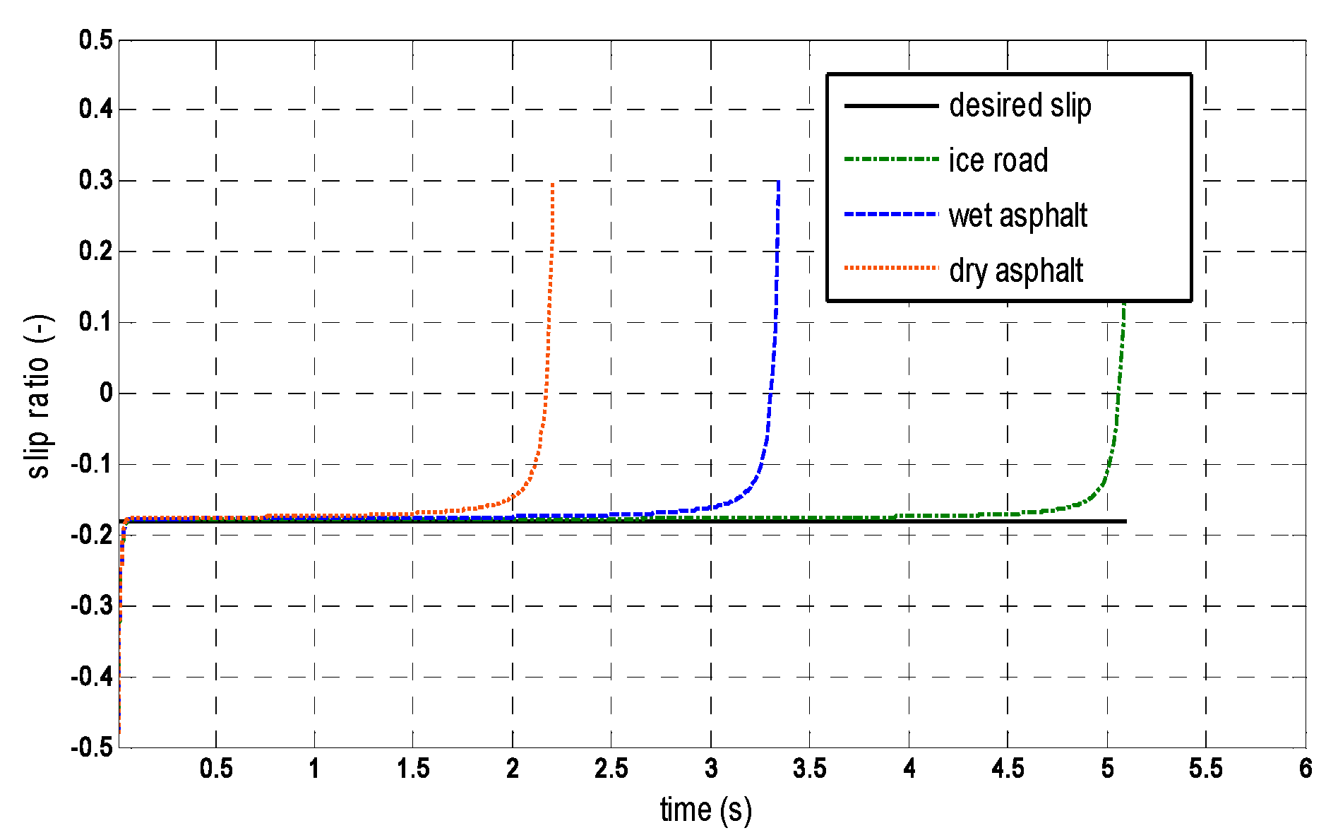
Different road conditions are used in simulations including dry asphalt road, wet asphalt road, and icy road, as shown in Figure 4, Figure 5 and Figure 6, and changing road surface conditions are shown in Figure 7, Figure 8 and Figure 9.
From the simulation results, the vehicle can track the vehicle speed well and the slip ratio is always maintained at the desired value through the adjustment of the adaptive controller regardless of the road surface condition. The braking torque is within the limit value and decreases as the road adhesion coefficient decrease. Thus, the proposed method presents strong robustness for the road surface conditions. Although the stopping time and braking distance are increased along with the decrease of the road adhesion coefficient, the controller exhibits good brake performance. Even on the road with a low adhesion coefficient, the control system is very stable and the wheel cannot be locked.
In order to verify the effectiveness, an extreme situation is considered in Figure 7, Figure 8 and Figure 9. In this case, the road condition is constantly changing from 0.8 to 0.3. With the help of the real-time road condition observer and the controller the adaptive feedback regulation to the road disturbance, the brake performance is not affected. Furthermore, better road adaptability of the adaptive controller has also been verified.

4.2. Simulation Comparison with SMC Method

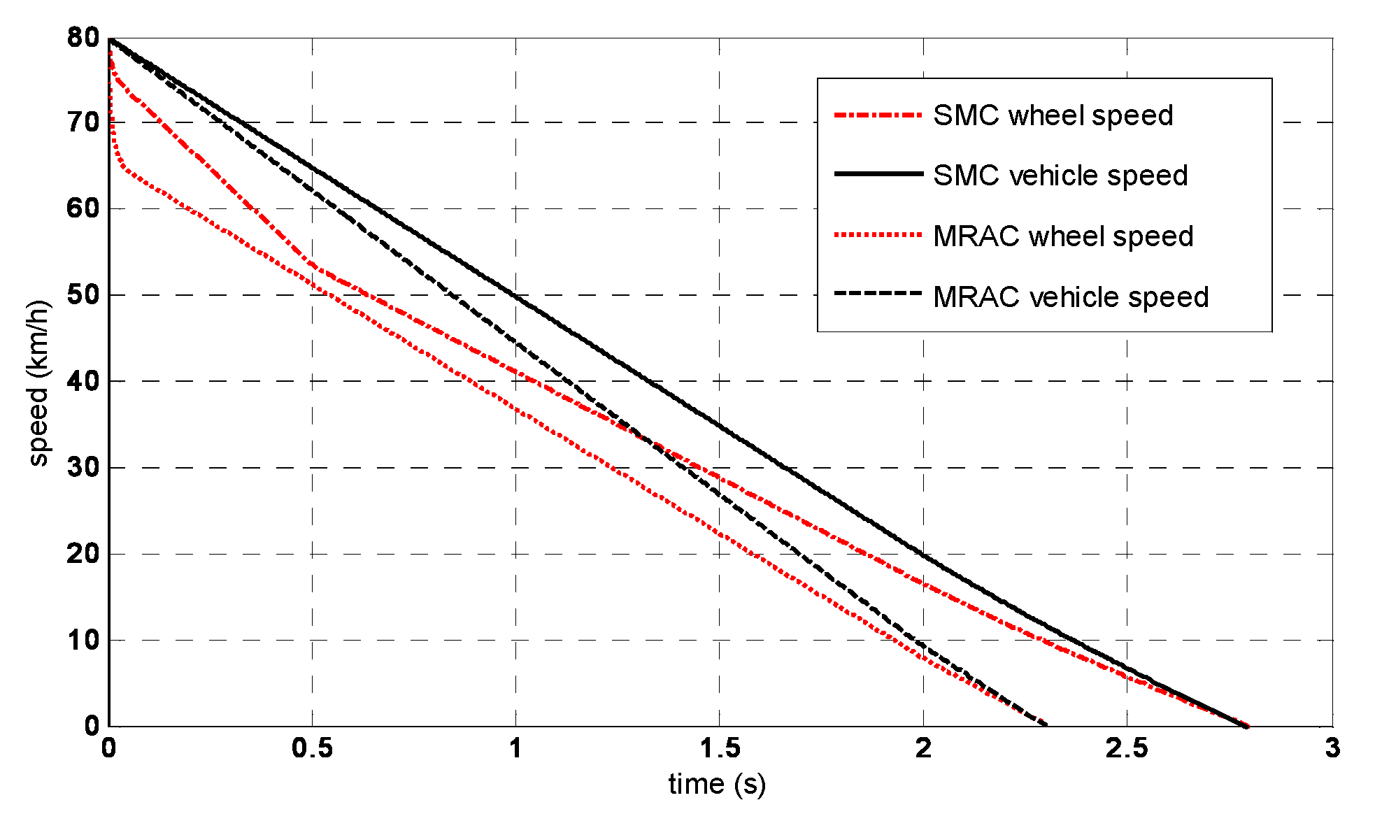
To better evaluate the proposed MRAC method, simulation comparisons with the SMC method are discussed. From the simulation results on the dry asphalt road in Figure 10 and Figure 11, both methods have achieved good vehicle speed tracking and desired slip ratio control under the same road conditions and the same initial braking velocity (80 km/h). Table 3 shows the detailed braking performance of the two methods.
From the simulation results, the MRAC has shorter braking distance, shorter braking time, and smaller tracking error compared to SMC. The braking distance and braking time of MRAC are correspondingly shortened by approximately 20% regardless of any road circumstances. The slip ratio output of SMC indicates the typical character of chattering around the desired value. Therefore, the brake torque is fully utilized through the control of the slip ratio and MRAC has better control performance and road condition adaptability.

4.3. Simulation Research with Uncertainties and Modeling Errors

To verify the robustness of the MRAC system, the modeling errors or uncertain disturbances are considered. For system (5), the parameter uncertainties and changes are considered. Firstly, the parameter of friction coefficient c f in the simulation is selected as 0.01, 0.4, and 0.8, respectively and the wheel rolling radius is selected as 90%, 100%, and 110% of r w in Figure 12 and Figure 13. Subsequently, the vehicle load variation is taken into account in the simulations. The additional change of load Δ d is given by
Δ d = C 1 sin ( 2 π f 1 ) + C 2 sin ( 2 π f 2 )
where C 1 = 80 , f 1 = 3.5 Hz, C 2 = 20 , f 2 = 8 Hz. Figure 14 shows the load variation and the corresponding control results are shown in Figure 15.
.
From the results, although the load wheel and rolling radius of the vehicle fluctuate and change in a certain range of friction coefficient, the controller can still achieve good control performance by the adaptive mechanism and the slip ratio is well controlled. The MRAC has good performance and strong robustness for the parameter uncertainties and modeling errors based on the road observer.

5. Conclusions

In this paper, a model reference adaptive control method integrated with road adhesion coefficient observer is presented. Firstly, the problem is formulated into vehicle speed tracking control through slip ratio tracking. Using the Lyapunov theory, a road adhesion coefficient observer is designed to estimate the road conditions online, and it is integrated into the MRAC method to improve its robustness. In addition, an SMO vehicle speed observer is adopted to obtain the unknown vehicle speed. Simulations under different conditions including modeling errors, uncertain road condition, and vehicle load variation are carried out to verify the feasibility and robustness of the proposed methodology. Compared with the SMC method, MRAC demonstrated better performance including lower braking distances and time. Of course, there are still some problems to be solved; the influence of lateral slip could not be considered during the vehicle turning process which will probably be a topic for future studies.

Author Contributions

X.Z. and G.G. proposed the original idea for the study; methodology, X.Z. and G.G.; software. All authors have read and agreed to the published version of the manuscript.

Funding

This work is supported in part by National Natural Science Foundation of China (U1808205, 61573077 61973053, 51975089 and 51575079).

Acknowledgments

In this section you can acknowledge any support given which is not covered by the author contribution or funding sections. This may include administrative and technical support, or donations in kind (e.g., materials used for experiments).

Conflicts of Interest

The authors declare no conflict of interest.

References

  1. Zhang, W.; Guo, X.X. An ABS control strategy for commercial vehicle. IEEE Trans. Mech. 2015, 20, 384–392. [Google Scholar]
  2. Xu, G.Q.; Xu, K.; Zheng, C.H.; Zahid, T. Optimal operation point detection based on force transmitting behavior for wheel slip prevention of electric vehicles. IEEE Trans. Intell. Transp. Syst. 2016, 17, 481–490. [Google Scholar] [CrossRef]
  3. Castillo, J.J.; Cabrera, J.A.; Guerra, A.J.; Simón, A. A novel electrohydraulic brake system with tire-road friction estimation and continuous brake pressure control. Trans. Ind. Electron. 2016, 63, 1863–1875. [Google Scholar] [CrossRef]
  4. Sun, W.C.; Zhang, J.H.; Liu, Z.Y. Two-time-scale redesign for antilock braking systems of ground vehicles. IEEE Trans. Ind. Electron. 2019, 66, 4577–4586. [Google Scholar] [CrossRef]
  5. Reza, H.; Alireza, B.H. Efficient antilock braking by direct maximization of tire-road frictions. IEEE Trans. Ind. Electron. 2011, 58, 3593–3600. [Google Scholar]
  6. Castro, R.D.; Araújo, R.E.; Freitas, D. Wheel slip control of EVs based on sliding mode technique with conditional integrators. IEEE Trans. Ind. Electron. 2013, 60, 3256–3271. [Google Scholar] [CrossRef]
  7. Fazeli, A.; Zeinali, M.; Khajepour, A. Application of adaptive sliding mode control for regenerative braking torque control. IEEE Trans. Mech. 2012, 17, 745–755. [Google Scholar] [CrossRef]
  8. Amodeo, M.; Ferrara, A.; Terzaghi, R.; Vecchio, C. Wheel slip control via second-order sliding-mode generation. IEEE Trans. Intell. Transp. Syst. 2010, 11, 122–131. [Google Scholar] [CrossRef]
  9. Tang, Y.; Wang, Y.; Han, M.; Lian, Q. Adaptive fuzzy fractional-order sliding mode controller design for antilock braking systems. J. Dyn. Syst. Meas. Control. 2016, 138, 122–130. [Google Scholar] [CrossRef]
  10. Lin, C.M.; Hsu, C.F. Self-Learning fuzzy sliding-mode control for antilock braking systems. IEEE Trans. Control Syst. Technol. 2003, 11, 273–278. [Google Scholar] [CrossRef]
  11. Mi, C.T.; Lin, H.; Zhang, Y. Iterative learning control of antilock braking of electric and hybrid vehicles. IEEE Trans. Veh. Technol. 2005, 54, 486–494. [Google Scholar] [CrossRef]
  12. Paul, D.; Velenis, E.; Cao, D.; Dobo, T. Optimal μ-estimation based regenerative braking strategy for an AWD HEV. IEEE Trans. Transp. Electr. 2017, 3, 249–258. [Google Scholar] [CrossRef]
  13. Johansen, T.; Petersen, I.; Kalkkuhl, J.; Lüdemann, J. Gain-scheduled wheel slip control in automotive brake systems. IEEE Trans. Control Syst. Technol. 2003, 11, 799–811. [Google Scholar] [CrossRef]
  14. Qiu, Y.; Liang, X.; Dai, Z. Backstepping dynamic surface control for an anti-skid braking system. Control Eng. Pract. 2015, 42, 140–152. [Google Scholar] [CrossRef]
  15. Rath, J.J.; Veluvolu, K.C.; Defoort, M. Simultaneous estimation of road profile and tire road friction for automotive vehicle. IEEE Trans. Veh. Technol. 2015, 64, 4461–4471. [Google Scholar] [CrossRef]
  16. Han, K.; Hwang, Y.; Lee, E.; Choi, S. Robust estimation of maximum tire-road friction coefficient considering road surface irregularity. Int. J. Automot. Technol. 2015, 17, 415–425. [Google Scholar] [CrossRef]
  17. Wu, J.; Huang, J.; Wang, Y.J.; Xing, K.X. Nonlinear disturbance observer-based dynamic surface control for trajectory tracking of pneumatic muscle system. IEEE Trans. Control Syst. Technol. 2014, 22, 440–455. [Google Scholar] [CrossRef]
  18. Mirkin, B.; Gutman, P.O. Robust adaptive output-feedback tracking for a class of nonlinear time-delayed plants. IEEE Trans. Automat. Contr. 2010, 55, 2418–2424. [Google Scholar] [CrossRef]
  19. Han, J.; Yu, S.; Yi, S. Adaptive control for robust air flow management in an automotive fuel cell system. Appl. Energy 2017, 190, 73–83. [Google Scholar] [CrossRef]
  20. Elzaghir, W.; Zhang, Y.; Natarajan, N.; Massey, F.; Mi, C. Model reference adaptive control for hybrid electric vehicle with dual clutch transmission configurations. IEEE Trans. Veh. Technol. 2018, 67, 991–999. [Google Scholar] [CrossRef]
  21. Subudhi, B.; Ge, S.S. Sliding-mode-observer-based adaptive slip ratio control for electric and hybrid vehicles. IEEE Trans. Intell. Transp. Syst. 2012, 13, 1617–1626. [Google Scholar] [CrossRef]
  22. Wang, B.; Huang, X.Y.; Wang, J.M. A robust wheel slip ratio control design combining hydraulic and regenerative braking systems for in-wheel-motors-driven electric Vehicles. J. Frankl. Inst. 2015, 352, 577–602. [Google Scholar] [CrossRef]
  23. Yin, G.; Jin, X.J. Cooperative control of regenerative braking and antilock braking for a hybrid electric vehicle. Math. Probl. Eng. 2013, 4, 1–9. [Google Scholar] [CrossRef]
  24. Wang, Z.; Zhu, J.; Zhang, L. Automotive ABS/DYC coordinated control under complex driving conditions. IEEE Access. 2018, 6, 32769–32779. [Google Scholar] [CrossRef]
  25. Pacejka, H.B.; Bakker, E. The Magic Formula tyre model. Veh. Sys. Dyn. 1992, 21, 1–18. [Google Scholar] [CrossRef]
  26. Burckhardt, M. Fahrwerktechnik Radschlupfregelsysteme; Vogel-verlag: München, Germnay, 1993. [Google Scholar]
  27. Canudas, D.W.C.; Olsson, H.; Aostrcom, K.J. A new model for control of systems with friction. IEEE Trans. Auto. Contr. 1995, 40, 419–425. [Google Scholar] [CrossRef]
  28. Bhandari, R.; Patil, S.; Singh, R.K. Surface prediction and control algorithms for anti-lock brake system. Transp. Res. Part C. 2012, 21, 181–195. [Google Scholar] [CrossRef]
  29. Harifi, A.; Aghagolzadeh, A.; Alizadeh, G.; Sadeghi, M. Designing a sliding mode controller for slip control of antilock brake systems. Transp. Res. Part C Emer. Technol. 2008, 16, 731–741. [Google Scholar] [CrossRef]
  30. Popov, V.M. Hyper-Stability of Control System; Springer: New York, NY, USA, 1973. [Google Scholar]
  31. Qu, Z.; Dawson, D.M.; Lim, S.Y.; Dorsey, J.F. A new class of robust control laws for tracking of robots. Int. J. Robot. Res. 1994, 13, 355–363. [Google Scholar]
Figure 1. Quarter-vehicle braking model.
Applsci 10 03459 g001
Figure 2. Quarter-vehicle braking model.
Applsci 10 03459 g002
Figure 3. Diagram of slip ratio MRAC system.
Applsci 10 03459 g003
Figure 4. Vehicle and wheel speed under different road conditions.
Applsci 10 03459 g004
Figure 5. Slip ratio under different road conditions.
Applsci 10 03459 g005
Figure 6. Braking torque under different road conditions.
Applsci 10 03459 g006
Figure 7. Road adhesion coefficient observer output.
Applsci 10 03459 g007
Figure 8. Vehicle and wheel speed under varying road conditions.
Applsci 10 03459 g008
Figure 9. Slip ratio under varying road conditions.
Applsci 10 03459 g009
Figure 10. Vehicle speed and wheel speed of MRAC and SMC.
Applsci 10 03459 g010
Figure 11. Slip ratio of MRAC and SMC.
Applsci 10 03459 g011
Figure 12. Slip ratio with different friction coefficient.
Applsci 10 03459 g012
Figure 13. Slip ratio with different r w
Applsci 10 03459 g013
Figure 14. Vehicle load variation.
Applsci 10 03459 g014
Figure 15. Slip ratio with load variation.
Applsci 10 03459 g015
Table 1. Vehicle Parameters.
SymbolQuantityValue
m¼ Car vehicle mass350 kg
JInertia0.65 kg m2
rwWheel radius0.31 m
cfFriction coefficient0.4
cvAir resistance coefficient0.595 N/(m2 s2)
nwNumber of brake wheel4
Table 2. Model Reference Adaptive Controller Parameters.
ParameterValueParameterValue
k01600k020.045
k110.1k120.005
g010.01g020.0005
l011l020.002
Table 3. Braking Performance.
Road ConditionsBraking Distance (m)Improved
SMCMRAC
Dry asphalt33.625.524%
Wet asphalt43.937.215%
Ice road85.660.822%
Road ConditionsBraking Time (s)Improved
SMCMRAC
Dry asphalt2.82.319%
Wet asphalt3.93.519%
Ice road7.75.429%