Article

Fingering Instability of a Gravity-Driven Thin Film Flowing Down a Vertical Tube with Wall Slippage

1
School of Transportation and Vehicle Engineering, Shandong University of Technology, Zibo 255000, China
2
Department of Engineering Mechanics, College of Pipeline and Civil Engineering, China University of Petroleum (East China), Qingdao 266580, China
3
Institute of Sound and Vibration Research, Hefei University of Technology, Hefei 230009, China
*
Author to whom correspondence should be addressed.
Appl. Sci. 2020, 10(1), 76; https://doi.org/10.3390/app10010076
Submission received: 27 November 2019 / Revised: 12 December 2019 / Accepted: 17 December 2019 / Published: 20 December 2019

Abstract

:
Inspired by the antiwetting property of pitcher plants, specialists have designed different functional material with slippery surfaces, and a directional slippery surface has been fabricated. This paper considers a gravity-driven liquid film coating the interior surface of a vertical tube, and different slippery lengths in the azimuthal direction and the axial direction are taken into account. The evolution equation of coating flow is derived using the thin film model, and time responses for two dimensional flow are calculated. Linear stability analysis (LSA) is given based on the traveling wave solutions, demonstrating that the axial slippery effect suppresses the flow instability and causes a larger traveling wave speed. Simultaneously, the azimuthal slippery effect plays a destabilizing role for perturbations with small wavenumbers and it is stabilizing for large wavenumbers. Direct simulations of the fingering flow patterns agree well with the linear stability analysis. Our results offer insight into the influence of wall slippage on the flow stability of liquid in petroleum engineering.

1. Introduction

Thin film flowing and droplet spreading are commonly encountered in chemical engineering, nuclear industry and materials sciences. The coating examples show that the free interface of a liquid film easily breaks into fingers resulting from the capillary effect [1,2,3]. The understanding of the dynamics and flow stability of liquid films is essential to control heat and mass transport processes.
To model the thin film flows, lubrication approximation, a thin film model and weighted residual model have been introduced in previous studies [4,5,6]. In the modeling of the liquid film, assumption of a small averaged thickness is crucial [7,8]. These modeling methods were also applied in dynamical contact line problems [9,10,11,12]. Kondic [13] and Lin [14,15] provided a systematic analysis to deal with the contact line instability problem, and the method was easy to implement [16,17]. Based on the governing equations, the relationship between different parameters and the surface instability was analyzed by linear stability analysis (LSA) [18,19].
In recent years, the spreading and falling of the liquid films on different substrates have been received much attention. It was found the curvature and property of the substrate played important roles in the film flows [20,21,22,23,24]. The liquid film flowing down a cylinder/fiber was more unstable than that flowing on an inclined plane [25]. As a common situation in interstifial flow, thin liquid film flowing on porous medium exhibits interesting dynamical phenomena. Ding and Liu [26,27] discovered that the film flowing on a porous vertical cylinder was more unstable and the increasing permeability of the porous medium significantly enhanced the destabilizing effect. The slippery effect often has a connection with wettability and porosity of the materials [28,29,30]. Recently, inspired by the good antiwetting property of nepenthes pitcher plants, specialists designed various slippery liquid-infused porous substrates similar to the microstructures and functions of pitcher plants [31,32,33]. Moreover, liquid-infused surface with directional slippery lengths was fabricated making use of immobilized lubricant menisci [34]. It is necessary to understand the thin film flow on these biomimetic surfaces, as these structures are usually designed for water collection and transportation.
In the analysis, the influence of the porous medium was usually reduced as a slip condition [35,36]. The effect of a slip on the primary instability was investigated by Samanta et al. [37,38]. It was found the slip played a destabilizing role close to the instability onset, while the flow was stabilizing at larger values of the Reynolds number. Ding [39] investigated the coupling action of the thermocapillary effect and slippery effect, concluding that the instability was enhanced as the slippery length increased. Chao [40] studied the dynamics of falling films down a cylinder in the presence of wall slippage, and also found that wall slippage enhanced the capillary instability. All the aforementioned investigations were concentrated on a substrate with slippery length in only one direction. However, the substrates used in biomedical applications usually exhibit anisotropic behavior. Therefore, this paper mainly focuses on the influence of the anisotropic slippery length on the surface instability of thin films flowing down a vertical tube.
The rest of this paper is organized as follows: In Section 2, the mathematical model is conducted based on the thin film model and two dimensional (2D) evolution is displayed. In Section 3, linear stability analysis is carried out based on traveling wave solutions. To verify the linear stability analysis, three dimensional (3D) flow simulations with random perturbations are displayed in Section 4, and some conclusions are briefly summarized in Section 5.

2. Mathematical Modeling

2.1. Governing Equations and Boundary Conditions

Figure 1 shows a gravity-driven liquid film flowing down a vertical tube, where the interior surface of the tube is assumed to be a directional slippery liquid-infused surface. A cylindrical coordinate ( r , θ , z ) is applied here. The radius of the tube is R and the different slippery lengths in azimuthal and axial directions are denoted by β θ and β z , respectively. Under the driven force of gravity g, the liquid film flows and breaks into fingers. The thickness of the film is defined by h ( θ , z , t ) , where t is time. To study thin film flows with contact lines, a given slip boundary condition or a precursor model are both effective [13]. Considering that the substrate is slippery, we use the precursor model to drive the governing equation, and the thickness of the precursor film is defined by b. The liquid is viscous and incompressible, and the constant density and viscosity of the fluid are ρ and μ , respectively.
For the liquid, the continuity equation and Navier-Stokes equations are satisfied:
1 r ( r u ) r + 1 r v θ + w z = 0
ρ D u D t v 2 r = p r + μ 2 u u r 2 2 r 2 v θ
ρ D v D t + u v r = 1 r p θ + μ 2 v v r 2 + 2 r 2 u θ
ρ D w D t = p z + μ 2 w + ρ g
where D / D t represents the material derivative and 2 is the Laplace operator in cylindrical coordinate, given as follows:
D D t = t + u r + v r θ + w z
2 = 2 r 2 + 1 r r + 1 r 2 2 θ 2 + 2 z 2
where u = ( u , v , w ) are velocities related to coordinates ( r , θ , z ) and p is the pressure. In the following text, the pressure of the ambient gas is denoted by p g .
For the directional slippery wall, slip boundary conditions are applied in θ direction and z direction while the non-slip boundary condition is applied in the r direction:
u = 0 , v = β 1 v r , w = β 2 w r
Here, β 1 and β 2 are the slippery length in θ direction and z direction, respectively, and v r = v r and w r = w r are partial derivative of velocity with respect to the coordinate r. Unless stated otherwise, the subscripts in this paper denote the partial derivative.
At the free surface r = R h , the balances of normal and tangential stresses should be satisfied:
( P P ) · n = s σ + σ ( · n ) n
where P = μ [ u + u T ] and P = ( p p g ) I are the stress tensor and pressure tensor, respectively. s is the surface gradient and n is the unit vector normal to surface. σ is the surface tension and s · n means the averaged curvature of the free surface.
The kinematic condition is given at the free interface:
h t + 1 r θ R h R v d r + z R h R w d r = 0

2.2. Scalings and Non-Dimensionalization

In order to nondimensionalize the system, we introduce the following scales:
( r , z , h ) = ( r R , z R , h R ) , ( u , v ,   w ) = ( u W ,   v W , w W ) ,   p = p p 0 ρ g R ,   t = t T
The characteristic velocity scale W and time scale T are given as:
W = ρ g R 2 μ , T = R W
The primes are dropped for simplicity and the nondimensionlized continuity equation and the N-S equations become:
1 r ( r u ) r + 1 r v θ + w z = 0
R e D u D t v 2 r = p r + 2 u u r 2 2 r 2 v θ
R e D v D t + u v r = 1 r p θ + 2 v v r 2 + 2 r 2 u θ
R e D w D t = p z + 2 w + 1
where R e = g W h 0 2 μ denotes the Reynold number.
Dimensionless boundary conditions at the fluid-solid interface are expressed as:
u = 0 , v = β θ v r , w = β z w r
where β θ = β 1 / R and β z = β 2 / R are the dimensionless slippery lengths. The dimensionless kinematic condition (9) at the liquid-air interface in integral form remains the same:
h t + 1 r θ R R h v d r + z R R h w d r = 0
With the scalings, dimensionless boundary conditions for balances of normal and tangential stresses become:
p + ( P · n ) · n = 1 C K ( h )
( P · n ) · τ i = 0
where K ( h ) is the mean curvature, composed by the principal curvature of the interface and the curvature of the substrate. C = μ W / σ 0 is the capillary number and τ i ( i = 1 , 2 ) denotes the unit vector tangential to surface.
Considering that the mean thickness of the liquid film is much smaller than the size in the other two directions, a new coordinate r = R ϵ x is applied in the radial direction. ϵ = h 0 / R < < 1 is a small parameter, where h 0 is the characteristic thickness of the thin film. The variables can be expanded as a perturbation series of ϵ [40]:
u = ϵ 3 u 0 + , v = ϵ 2 v 0 + , w = ϵ 2 w 0 + , p = p 0 + ,
Using the above solutions and neglecting the terms with higher orders of ϵ , the continuity equation and N-S equations at leading order are derived:
u x 0 + v θ 0 / R + w z 0 = 0
p x 0 = 0
v x x 0 = 1 R p θ 0
w x x 0 = p z 0 1
Applying the rescaled β θ = ϵ 1 β θ and β z = ϵ 1 β z [40], and droping the primes, the boundary conditions at x = 0 become:
u 0 | x = 0 = 0 , v 0 | x = 0 = β θ v x 0 , w 0 | x = 0 = β z w x 0
The boundary conditions at the liquid-air interface become:
v x 0 | x = h = 0
w x 0 | x = h = 0
Normal stress is balanced by the pressure and surface tension, giving:
p 0 | x = h = ϵ C 1 ϵ ( R ϵ h ) 2 h ϵ C 1 ϵ R + h R 2 2 h
where the first and the second terms in the right hand are obtained using the Taylor expansion. The difference between a tube and a cylinder is that the second term in Equation (28) has opposite signs.
From Equations (23)–(28), the functions ( v , w ) of the zeroth order are obtained:
v 0 = 1 2 ( p 0 R θ ) ( x 2 2 h x 2 β θ h )
w 0 = 1 2 ( p 0 z 1 ) ( x 2 2 h x 2 β z h )
Substituting u 0 and v 0 into the kinematic boundary condition of integral form:
h t + R θ 0 h v 0 d x + z 0 h w 0 d x = 0
The evolution equation for the thin film flow with dynamical contact line are finally obtained:
h t + z h 3 3 + β z h 2 + · Θ ( h ) h R 2 + 2 h = 0
where = [ θ , z ] and Θ ( h ) is a coefficient matrix:
Θ ( h ) = h 3 3 C a + β θ h 2 C a 0 0 h 3 3 C a + β z h 2 C a
where C a = C / ϵ is the modified capillary number [16,40]. In this study, we mainly focus on the slippery effect, and the effect of capillary number C a has little effect on the results. Therefore, C a = 1 is to be set in the following discussions.

2.3. Two Dimensional Simulations

The most interesting problem we want to know is whether the traveling contact line is stable. Previous studies has discovered that the steady state shape of 2D flow matters a lot to the surface instability [13,15]. In other words, fingering instability in θ direction has essential relationships with the steady base flow independent of coordinate θ . Besides, the base flow plays an important role in traveling wave solutions and linear stability analysis. Therefore, the two dimensional flow is firstly investigated here, assuming that the evolution equation is independent of the coordinate θ . Then the evolution equation is simplifies to:
h t + z h 3 3 + β z h 2 + z h 3 3 + β z h 2 z h R 2 + 2 h = 0
An initial condition profile h 0 is applied to start the thin film flow. The initial condition is a smooth curve in the form of hyperbolic tangent function [13]:
h 0 = 1 + b 2 1 b 2 tanh ( z z 0 )
where z 0 is the position of the contact line. From the profile, it is seen that h is constant far away from the contact line. A constant flux boundary condition is approximated well by setting h ( 0 , t ) = 1 and h ( z m a x , t ) = b , where b is the thickness of the precursor layer.
Equation (34) is solved using the finite difference method by a MATLAB code. Firstly, the influence of the slippery length is discussed. The time evolution of the fluid profile with different slippery length is visualized in Figure 2, giving the screenshots for t = 70 and t = 140 . In the simulation, the slippery length is set to β z = 0 , β z = 0.025 , β z = 0.05 , β z = 0.075 and β z = 0.1 , respectively. Theoretically, a more significant influence will be induced to the responses if we give a larger slippery length β z . However, in fact, slip usually only occurs very close to the contact line, and this condition is a means of alleviating the stress singularity. Hence the value of the slippery length is given in a reasonable range [0,0.1] in this study. From Figure 2, we note the flow evolves into a traveling wave state after a period, and the traveling wave solutions are to be used in the linear stability analysis (LSA). Resulting from the capillary effect, the steady traveling wave profile has a large ridge at the fluid front, and a higher capillary ridge implies a stronger contact line instability. It has been stated that the profile will tend to the traveling wave shape regardless of the initial condition as long as the boundary conditions were satisfied [16]. Comparing the two graphs, it is seen that the flow travels faster with a bigger value of β z , and the bump becomes lower while the axial slippery effect is larger. Thin films are inclined to break when the bump is high, hence the fluid profile predicts that the thin film flows more stably when the axial slippery length is longer.
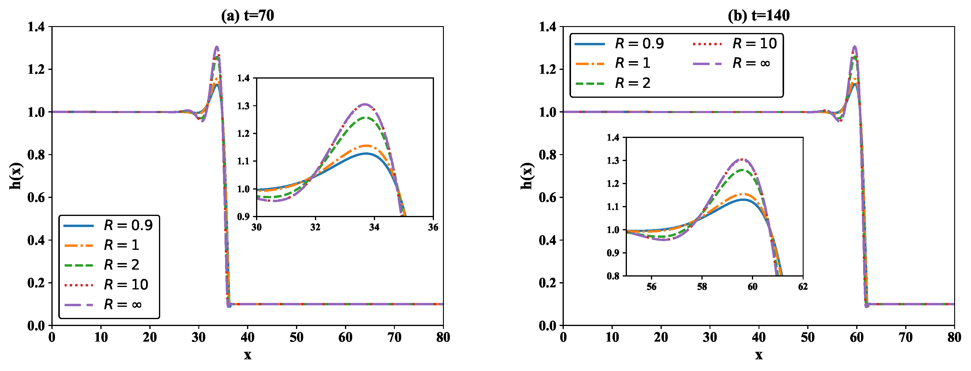
Figure 3 shows the situation for different substrate curvature. Tubes of different radius are used to test the influence of the substrate curvature. In the calculation, R = 0.9 , R = 1 , R = 2 , R = 10 and R = are employed and R = also corresponds to a vertical plane. It is seen that the capillary ridge appears at the same position after a specified time, indicating that radius of the tubes has no relationship with the traveling wave speed. Also, it can be found that a larger R corresponds to a larger capillary bump, contrary to the phenomenon in the thin film flow coating on a cylinder surface [16,25], because the substrate curvature contributes contrarily in the two cases. For a very large R > 10 , the influence of the substrate curvature is insignificant. From the graphs, we can deduced that increasing substrate curvature (smaller R) enhances the stability of the thin film flow, while a higher capillary ridge is induced by the larger substrate curvature, making the flow more unstable.
The contribution of the thickness of the precursor layer is investigated and displayed in Figure 4. Two phenomenons deserves attention: the flow travels slower with a thinner precursor layer and a thinner precursor layer induces a larger capillary ridge. The main reason for this is that the thinner precursor film causes more resistance than thicker films; hence, for a thinner precursor film, a lower fluid bump appears and travels more slowly.

3. Linear Stability Analysis

From the time responses, it is found that traveling wave solutions exist. Therefore, using the moving frame ξ = z c t , we can define a new thickness function H ( ξ ) , where c is the traveling wave speed. In the following analysis, H denotes the thickness function related to variable ξ while h represents the thickness function related to variables z and t. The governing evolution equation (34) becomes an ordinary differential equation related to only one variable:
c H ξ + h 3 3 + β z H 2 ξ + H 3 3 + β z H 2 H ξ R 2 + H ξ ξ ξ ξ = 0
Integrating Equation (36) once, a third-order differential equation is obtained:
c H + H 3 3 + β z H 2 + H 3 3 + β z H 2 H ξ R 2 + H ξ ξ ξ = d
where d denotes an integral constant.
Equation (37) is solved effectively by a finite difference code, the traveling wave solutions can be obtained. Here, the influence of the slippery length, substrate curvature and thickness of precursor layer are concerned. The traveling wave solutions for different parameters are shown in Figure 5. The influence of the slippery effect on the nonlinear behavior is shown in Figure 5a, and it can be found that a larger slippery length is related to a faster moving interfacial wave following a lower capillary ridge. The lower bump usually corresponds to a more stable flow. For different precursor thickness b, the traveling wave profiles are displayed in Figure 5b, the wave profile for different b presents a similar structure for different β z . Figure 5c gives traveling wave profiles for different R. The capillary ridge becomes larger with a bigger R, indicating that substrate curvature enhances the stability of the thin liquid film. Comparing Figure 2, Figure 3, Figure 4 and Figure 5, the traveling wave solutions show good agreement with the time evolution of the thin films.
Based on the boundary conditions H ( 0 , t ) = 1 , H ξ ( 0 , t ) = 0 , H ( ξ m a x , t ) = b , H ξ ( ξ m a x , t ) = 0 [13], the traveling wave speed of the contact line and the integral constant d are yielded as c = 1 + b + b 2 3 + β z ( 1 + b ) and d = b ( 1 + b ) 3 β z b . From the function of c, one can find a larger b is related to a larger traveling wave speed and similar conclusion can be obtained for β z , agreeing well with the time responses displayed in Figure 2, Figure 3 and Figure 4.
For the three dimensional problems, the solution can be simply assumed in the form of H ( t , ξ , θ ) = H ¯ ( ξ ) + ϵ H ( t , ξ , θ ) [17,23], where H ¯ ( ξ ) is the traveling wave solution (also called base solution) of Equation (37) and H ( t , ξ , θ ) is the perturbation. Substituting H ( t , ξ , θ ) into the governing Equation (34) and applying Equation (36), the governing Equation (32) becomes:
H t c H ξ + ξ ( H ¯ 2 H + 2 β z H ¯ H ) 1 + ξ ( 1 R 2 H ¯ + 2 H ¯ ) + ξ Θ z ( H ¯ ) ξ ( 1 R 2 H + 2 H ) + θ Θ θ ( H ¯ ) θ ( 1 R 2 H + 2 H )
where Θ z ( H ¯ ) = H ¯ 3 3 + β z H ¯ 2 and Θ θ ( H ¯ ) = H ¯ 3 3 + β θ H ¯ 2 . The perturbation H ( t , ξ , θ ) can be expressed as a superposition of a series of Fourier transforms [17,26], expressed as H ( t , ξ , y ) = H ^ e i q θ + σ ( q ) t , where q is the wavenumber and σ ( q ) relates to the growth rate. For every given wavenumber q, substituting H ( t , ξ , y ) = H ^ e i q θ + σ ( q ) t into Equation (38), Equation (38) transforms into a standard eigenvalue equation:
σ ( q ) H ^ = L H ^
Here only the largest real σ is to be used representing the largest eigenvalue of L and L is a linear operator with the matrix form:
L = c D 1 + ( 2 H ¯ D 1 H ¯ + 2 β z D 1 H ¯ ) ( 1 + κ D 1 H ¯ + D 3 H ¯ ) + ( H ¯ 2 D 1 H ¯ + 2 β z H ¯ D 1 H ¯ ) ( 1 + κ D 1 + D 3 q 2 D 1 ) + ( H ¯ 2 + 2 β z H ¯ ) ( κ D 1 H ¯ + D 3 H ¯ ) D 1 + ( κ D 2 H ¯ + D 4 H ¯ ) + Θ x ( H ¯ ) ( κ D 2 + D 4 q 2 D 2 ) + Θ θ ( H ¯ ) ( κ q 2 I q 2 D 2 + q 4 I )
where κ = 1 R 2 ; I represents the identity matrix, and D i ( i = 1 , 2 , 3 , 4 ) are finite difference matrix of i-th order. Using the difference matrix, we have H ¯ ξ = D 1 H ¯ , H ¯ ξ ξ = D 2 H ¯ , H ¯ ξ ξ ξ = D 3 H ¯ and H ¯ ξ ξ ξ ξ = D 4 H ¯ . Equation (40) is solved numerically to obtain the values of σ ( q ) for a given wavenumber q, following the work by Kondic [13]. Given a wavenumber, the eigenvalues of the matrix L are obtained by a MATLAB code, and the growth rate is related to the largest real value.
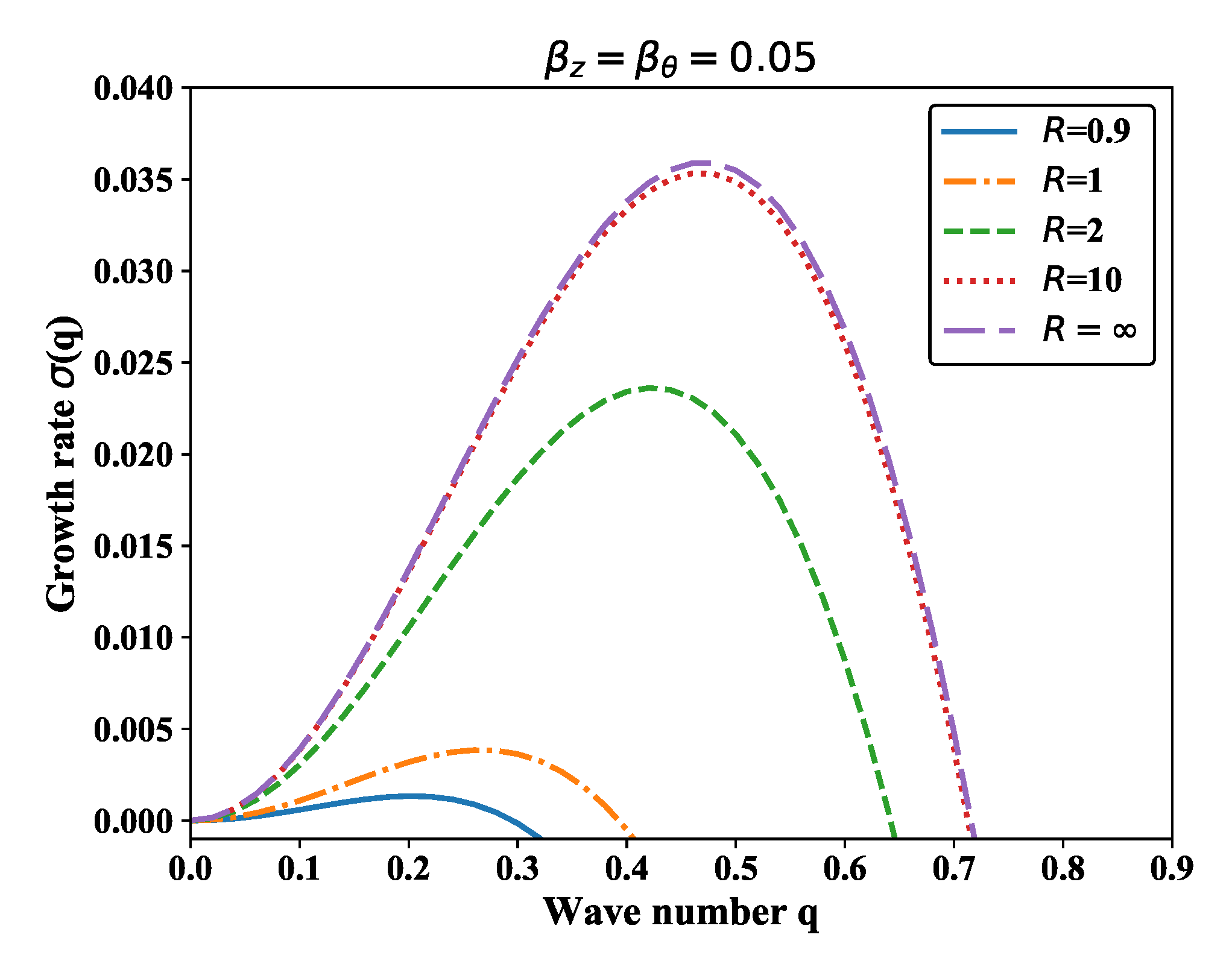
The growth rate σ ( q ) associated with different cylinder radius is illustrated in Figure 6. Each curve represents the largest eigenvalue of L versus the wavenumber q, and we can determine the range of unstable wavenumbers as ( 0 , q c ) with σ ( q c ) = 0 . For small wavenumber q < q c , the flow is always unstable. The dispersion curves illustrate that a smaller cylinder radius results in a larger growth rate and a bigger peak wavenumber (the value corresponding to the maximum growth rate). A smaller cut-off wavenumber q c is also found when the cylinder radius is smaller. For R = , the cylinder can be considered as a vertical plane, demonstrating that the thin film flow down a vertical tube is much more stable when given a certain perturbation. From the plots, it is seen that the substrate curvature greatly promotes the fingering instability, especially for the case of R < 1 .
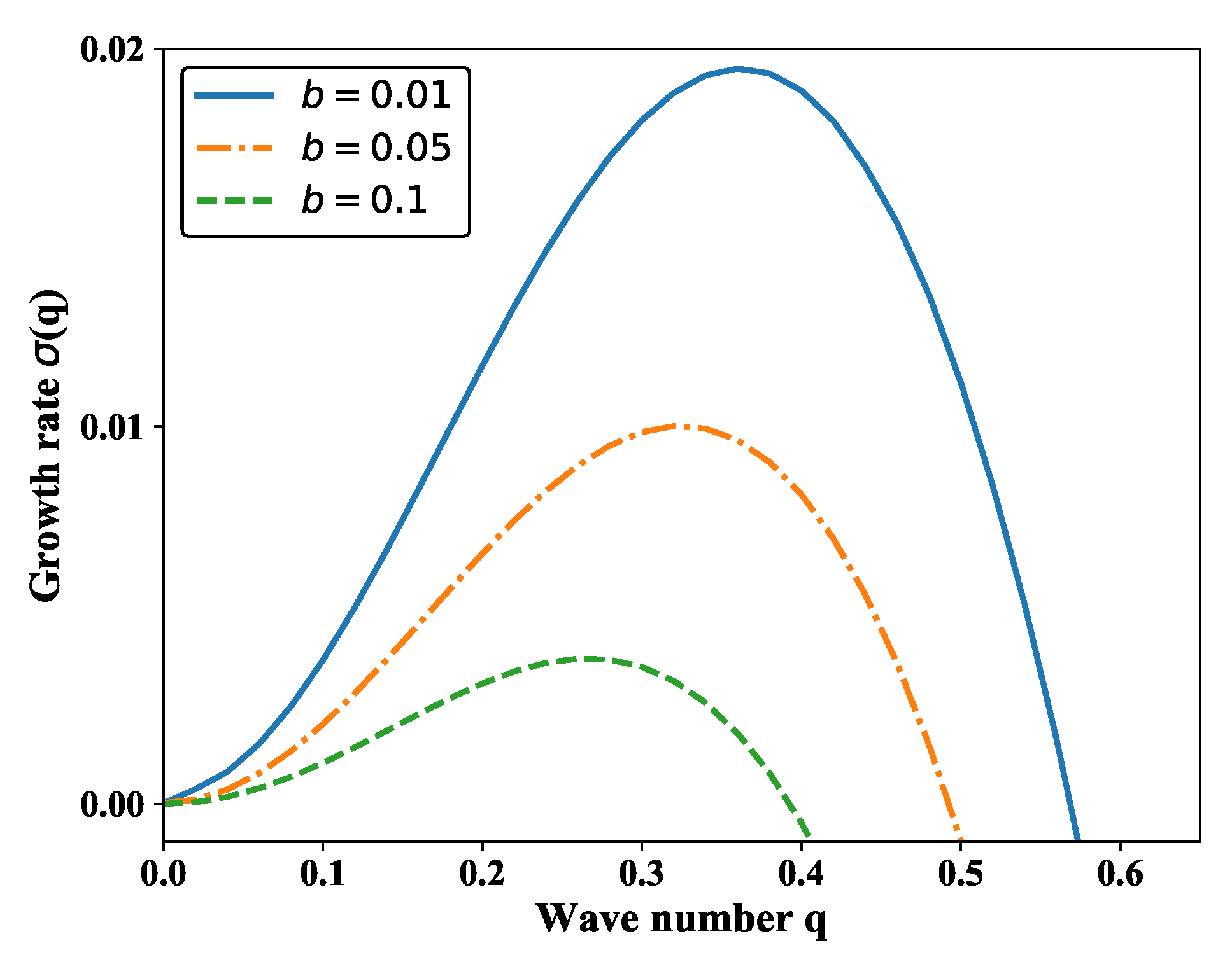
The dispersion curves for different thickness of precursor layer b are visualized in Figure 7. We note that a small thicknesses of the precursor layer is related to a much larger maximum growth rate, showing good consistency with the time responses. Much larger cutoff wavenumbers and peak wavenumbers are found for smaller b, demonstrating that both the strength and the wavenumber range of the surface instability are enhanced by a thinner precursor layer.
Figure 8 shows the growth rate for a tube with the isotropic slippery lengths, i.e., β θ = β z . As shown in Figure 8, both the growth rate and the peak wavenumber change small with the increase of slippery length, showing that the slippery effect impedes the surface instability. From the curves, we can find that with a larger slippery length, a smaller unstable range is determined as the q c is smaller. For β z = β θ = 0 , the range is [ 0 , 0.32 ] and for β z = β θ = 0.1 , the range is [ 0 , 0.48 ] .
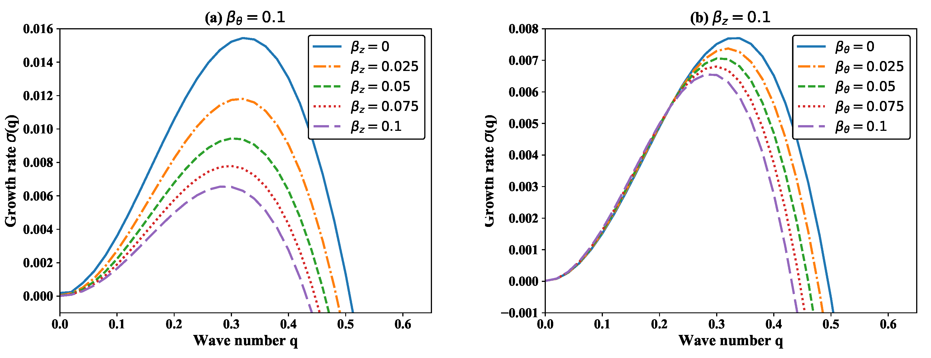
As introduced above, the slippery lengths are often different in the azimuthal and axial directions, as the properties of the substrate material are anisotropic, such as fibers and composite materials. Figure 9 and Figure 10 display the dispersion relations for different slippery lengths while β z β θ is taken into consideration. In Figure 9, the slippery effect in only one direction is considered while in Figure 10, the slippery effect in two directions is considered. From the two figures, the change of the growth rate displays similarly with a difference in the values. It is notable that the two slippery lengths β θ and β z play different roles in the flow stability. From Figure 9a and Figure 10a, a larger axial slippery length corresponds to a smaller growth rate of perturbation. Therefore, the surface instability is suppressed by the axial slippery length. In addition, the change in the growth rate is much more interesting when β θ increases. It can be seen that the growth rate changes slightly in the range [ 0 , q t ] , where q t is a turning point. If q < q t , the growth rate increases with the increase of azimuthal slippery length, while q > q t , the growth rate decreases with the increase of azimuthal slippery length. In other words, if the wavenumber of the perturbation is less than q t , the azimuthal slippery effect slightly enhances the surface instability, while the wavenumber of the perturbation exceeds q t , the azimuthal slippery effect suppresses the surface instability. Besides, for the two cases, both the peak wavenumber and the range of σ > 0 decreases with the increase of slippery length.

4. Numerical Simulation

In this section, the finite element method is applied to solve the governing equation in this section with the help of the open-source software Freefem++ [25,41]. FreeFem++ is a powerful programming language focused on solving partial differential equations using the finite element method. The growth rate σ ( q ) for imposed perturbations has been obtained by the linear stability analysis, relating to a wavenumber q. Using the wavenumber, we could calculate the most unstable mode of wavelength λ = 2 π / q in the azimuthal direction. Here, a similar initial condition used in 2D simulation is chosen, i.e., a smooth surface consisting of two flat regions. The two regions are connected by a tanh function at the initial front position z 0 . Far behind the contact line, the thickness is set to h ( θ , 0 , t ) = 1 and the thickness is set to h ( θ , z m a x , t ) = b far front of the contact line. A single mode perturbation is applied at the contact line [17], impelling the contact line to convex slightly into the streamwise direction, given as:
h 0 = 1 + b 2 1 b 2 tanh z z 0 A 0 cos ( 2 π θ R λ )
where A 0 is the amplitude of the small perturbation.
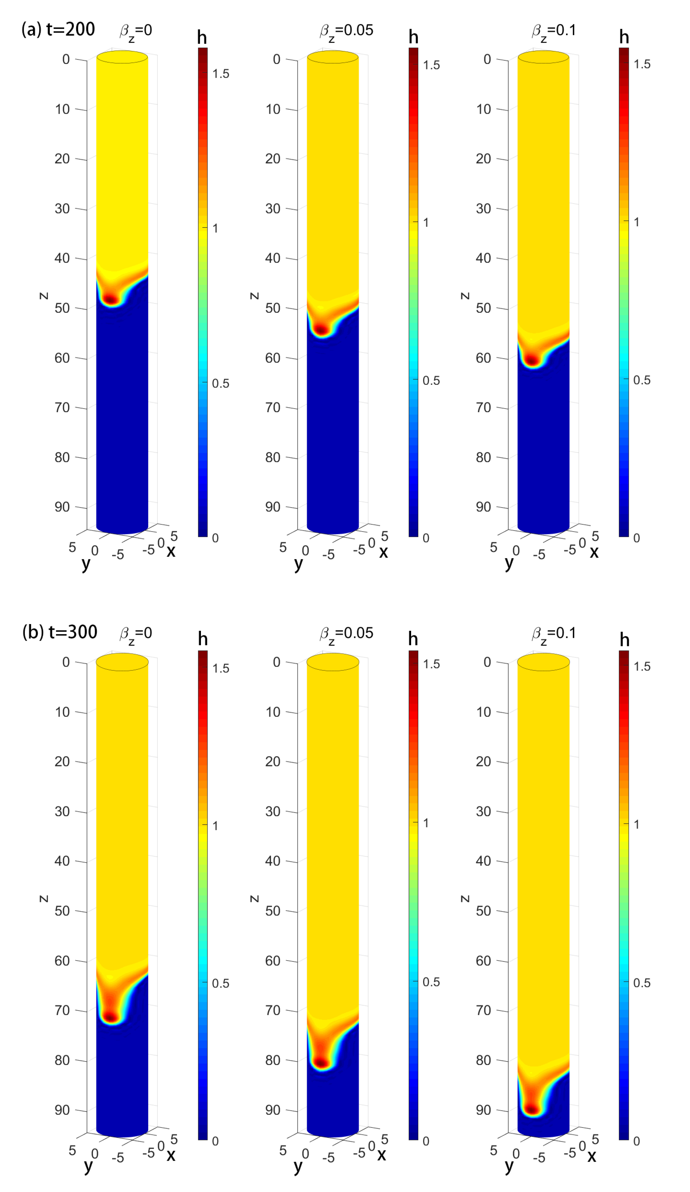
Figure 11 shows the single-mode perturbed thin film flows for different β z . The time profiles for t = 200 are shown in Figure 11a and the time profiles for t = 300 are shown in Figure 11b, and the thickness of the falling films is expressed using the color bar. To compare the influence of the two slippery lengths, a wavenumber of q = 0.2 is chosen, and related wavenumber length is 10 π , meaning that the radius of the tube is R = 5 . For β z = 0 , β z = 0.05 and β z = 0.1 , the growth rates σ ( q ) are 0.01058, 0.00678 and 0.00499, receptively. It has been concluded that the axial slippery length causes a larger traveling wave speed and suppresses the flow instability. From the 3D simulations, the flow travels much faster with a larger β z as expected, and the fingers for β z = 0 are longer than that for β z = 0.05 and β z = 0.1 , showing good consistency with the prediction of the linear stability analysis. From the 3D plots, only one finger appears as a single-mode perturbation is applied, and the circumference is a precise length of one single wavelength.
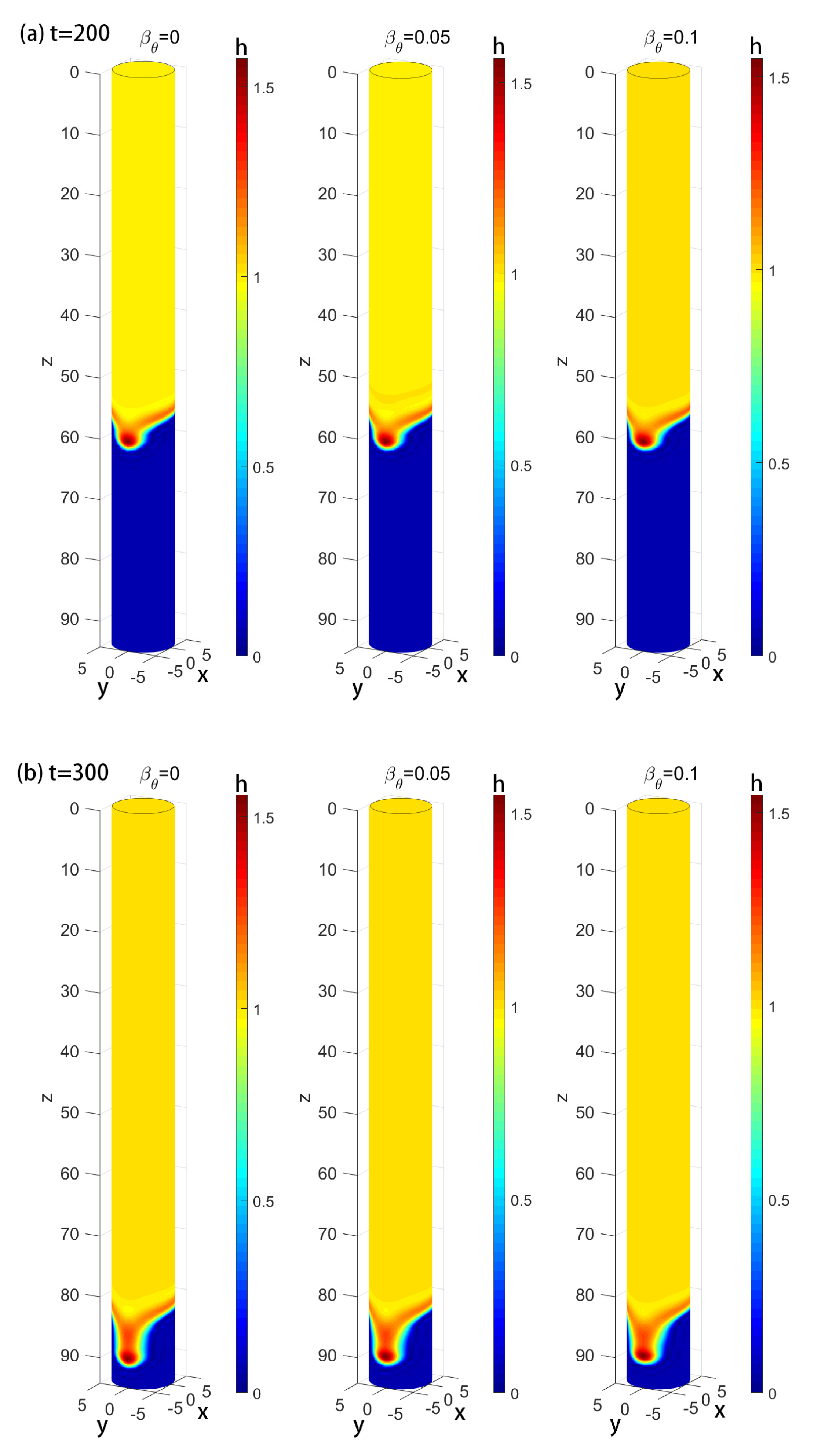
Time evolution of single-mode perturbed fluid films flowing down vertical tubes for different β θ are exhibited in Figure 12 and Figure 13. From the LSA, it is seen that the slippery effect plays opposite roles while different wavenumbers are applied. To verify the roles, the cases for q = 0.2 and q = 0.4 are simulated. In Figure 12, the wavenumber of 0.2 is also applied, and the radius is R = 5 . From the two graphs, it is seen the traveling wave speed has no relationship with the circumferential slippery effect. When q = 0.2 , the growth rate is 0.00490, 0.00495 and 0.00499, receptively for β θ = 0 , β θ = 0.05 and β θ = 0.1 . The contour plots in Figure 12 demonstrates that the fingers for β θ = 0 are a little longer than that for a larger β θ . However for q = 0.4 , the circumference is two times of the a single wavelength, and two fingers appears in each graph, as shown in Figure 13. For q = 0.4 , the growth rates are 0.00651, 0.00469 and 0.00275, corresponding to β θ = 0 , β θ = 0.05 and β θ = 0.1 . From the measurement, the maximum height is 1.5545, 1.5465 and 1.5333, respectively, also showing that the instability is impeded by the β θ .
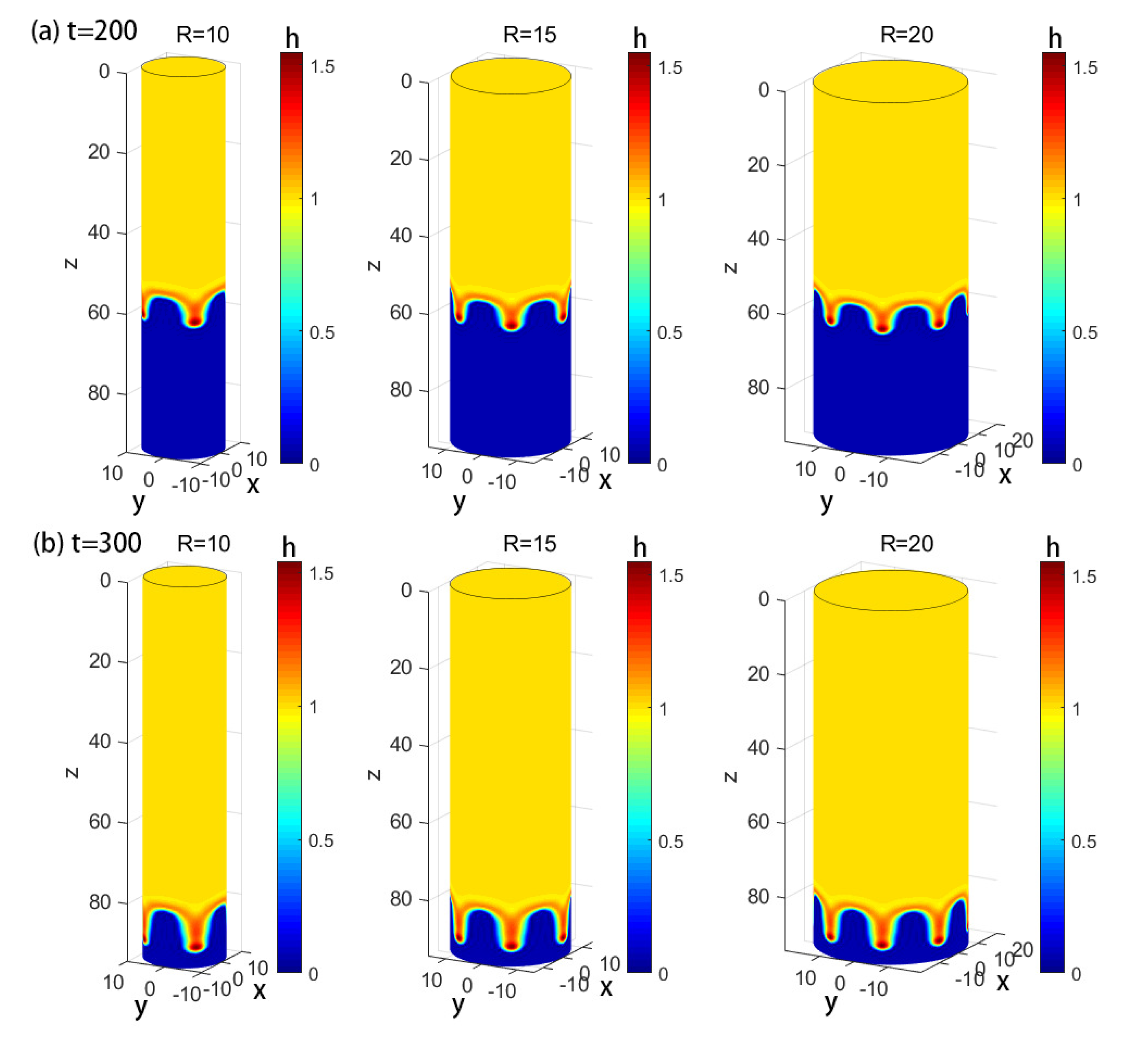
Figure 14 displays the time evolution of single-mode perturbed fluid films down vertical tubes of different radius R. Here R = 10 , R = 15 and R = 20 is applied, and a single-mode perturbation of q = 0.4 is still applied as an initial condition. The contour plot shows the film profile at t = 200 and t = 300 . The largest influence of the radius is changing the number of the fingers. It is found that with a larger radius of the cylinder, the number of fingers in the contact line is also larger. In Figure 13, the number of fingers is 2, and here the number is 4, 6 and 8, respectively. The number of the fingers is determined by the wavelength, hence the number of the fingers is the divisor of the circumference and wavelength related to the perturbation.

5. Conclusions

In the present paper, we investigated the fingering instability of a coating flow down a vertical tube with dynamic contact line, and the influence of the directional slippery substrate on the flow instability was analyzed. Based on the thin film theory, the governing equation for the thin film flow was derived, then the time responses for the axisymmetry model for different parameters were simulated, including the precursor thicknesses, the axial slippery length and the radius of the tube. Linear stability analysis was carried out based on the traveling wave solutions. Finally, three dimensional numerical simulations were given by the finite element method with the help of the open-source software Freefem++. Numerical simulations showed good agreement with linear stability analysis.
From the numerical simulations and the LSA, some conclusions were obtained: The thickness of the precursor layer induced a smaller capillary bump and causes the contact line to travel faster, while the radius of the tube promoted the surface instability. The slippery effect in the axial direction and the azimuthal direction acted differently thin film flows with dynamic contact lines. The axial slippery effect always played a stabilizing role while the azimuthal effect played two roles. When the wavenumber was smaller than a transfer wavenumber q t , the azimuthal effect slightly enhanced the flow instability, and when the wavenumber exceeded the critical value q t , the azimuthal effect impeded the flow instability.

Author Contributions

Conceptualization, C.M. and B.L.; methodology, C.M.; software, S.H.; validation, G.D.; formal analysis, C.M. and S.H.; data curation, G.D.; writing—original draft preparation, C.M.; writing—review and editing, C.M. All authors have read and agreed to the published version of the manuscript.

Funding

This research was funded the National Natural Science Foundation of China (Grant Nos. 11702162, 11972375 and 51975341) and Key Technology R & D Program of Shandong Province (Grant Nos. 2019GHZ001 and 2019RKB01041).

Acknowledgments

Chicheng Ma wants to acknowledge the help from Zijing Ding from Cambridge University.

Conflicts of Interest

The authors declare that they have no conflict of interest.

References

  1. Huppert, H.E. Flow and instability of a viscous current down a slope. Nature 1982, 300, 427–429. [Google Scholar] [CrossRef]
  2. Schwartz, L.W. Viscous flows down an inclined plane: Instability and finger formation. Phys. Fluids A 1989, 1, 443–445. [Google Scholar] [CrossRef]
  3. Bertozzi, A.L.; Brenner, M.P. Linear stability and transient growth in driven contact lines. Phys. Fluids A 1997, 9, 530–539. [Google Scholar] [CrossRef] [Green Version]
  4. Oron, A.; Davis, S.H.; Bankoff, S.G. Long-scale evolution of thin liquid films. Rev. Mod. Phys. 1997, 69, 931–980. [Google Scholar] [CrossRef] [Green Version]
  5. Diez, J.A.; Kondic, L.; Bertozzi, A. Global models for moving contact lines. Phys. Rev. E 2000, 63, 011208. [Google Scholar] [CrossRef] [Green Version]
  6. Diez, J.A.; Kondic, L. Computing three-dimensional thin film flows including contact lines. J. Comput. Phys. 2002, 183, 274–306. [Google Scholar] [CrossRef] [Green Version]
  7. Matar, O.K.; Kumar, S. Dynamics and stability of flow down a flexible incline. J. Eng. Math. 2007, 57, 145–158. [Google Scholar] [CrossRef]
  8. Craster, R.V.; Matar, O.K. Dynamics and stability of thin liquid films. Rev. Mod. Phys. 2009, 81, 1131–1198. [Google Scholar] [CrossRef]
  9. Marshall, J.S.; Wang, S. Contact-line fingering and rivulet formation in the presence of surface contamination. Comput. Fluids 2005, 34, 664–683. [Google Scholar] [CrossRef]
  10. Craster, R.V.; Matar, O.K. Numerical simulations of fingering instabilities in surfactant-driven thin films. Phys. Fluids 2006, 18, 032103. [Google Scholar] [CrossRef]
  11. Kalliadasis, S. Nonlinear instability of a contact line driven by gravity. J. Fluid Mech. 2000, 413, 355–378. [Google Scholar] [CrossRef]
  12. Leizerson, I.; Lipson, S.G.; Lyushnin, A.V. Finger Instability in Wetting-Dewetting Phenomena. Langmuir 2004, 20, 291–294. [Google Scholar] [CrossRef]
  13. Kondic, L. Instabilities in gravity-driven flow of thin fluid films. Siam Rev. 2003, 45, 95–115. [Google Scholar] [CrossRef] [Green Version]
  14. Lin, T.S.; Kondic, L. Thin films flowing down inverted substrates: Two dimensional flow. Phys. Fluids 2010, 22, 052105. [Google Scholar] [CrossRef] [Green Version]
  15. Lin, T.S.; Kondic, L.; Filippov, A. Thin films flowing down inverted substrates: Three-dimensional flow. Phys. Fluids 2012, 24, 022105. [Google Scholar] [CrossRef]
  16. Mayo, L.C.; McCue, S.W.; Moroney, T.J. Gravity-driven fingering simulations for a thin liquid film flowing down the outside of a vertical cylinder. Phys. Rev. E 2013, 87, 053018. [Google Scholar] [CrossRef] [Green Version]
  17. Hu, B.; Kieweg, S.L. Contact line instability of gravity-driven flow of power-law fluids. J. Non-Newton. Fluid Mech. 2015, 225, 62–69. [Google Scholar] [CrossRef] [Green Version]
  18. Thiele, U.; Knobloch, E. Front and back instability of a liquid film on a slightly inclined plate. Phys. Fluids 2003, 15, 892–907. [Google Scholar] [CrossRef] [Green Version]
  19. Perazzo, C.A.; Gratton, J. Thin film of non-Newtonian fluid on an incline. Phys. Rev. E 2003, 67, 016307. [Google Scholar] [CrossRef] [Green Version]
  20. Kondic, L.; Diez, J. Pattern formation in the flow of thin films down an incline: Constant flux configuration. Phys. Fluids 2000, 13, 3168–3184. [Google Scholar] [CrossRef]
  21. Diez, J.A.; González, A.G.; Kondic, L. Instability of a transverse liquid rivulet on an inclined plane. Phys. Fluids 2012, 24, 032104. [Google Scholar] [CrossRef] [Green Version]
  22. Chao, Y.; Ding, Z. Thermocapillary thin-film flows on a compliant substrate. Phys. Rev. E 2019, 99, 043101. [Google Scholar] [CrossRef]
  23. Ding, Z.; Willis, A.P. Relative periodic solutions in conducting liquid films flowing down vertical fibres. J. Fluid Mech. 2019, 873, 835–855. [Google Scholar] [CrossRef] [Green Version]
  24. Ding, Z.; Liu, Z.; Liu, R.; Yang, C. Breakup of ultra-thin liquid films on vertical fiber enhanced by Marangoni effect. Chem. Eng. Sci. 2019, 199, 342–348. [Google Scholar] [CrossRef]
  25. Ma, C. Fingering instability analysis for thin gravity-driven films flowing down a uniformly heated/cooled cylinder. Int. J. Heat Mass Trans. 2019, 136, 719–729. [Google Scholar] [CrossRef]
  26. Ding, Z.; Wong, T.N.; Liu, R.; Liu, Q. Viscous liquid films on a porous vertical cylinder: Dynamics and stability. Phys. Fluids 2013, 25, 064101. [Google Scholar] [CrossRef]
  27. Liu, R.; Ding, Z. Stability of viscous film flow coating the interior of a vertical tube with a porous wall. Phys. Rev. E 2017, 95, 053101. [Google Scholar] [CrossRef] [Green Version]
  28. Liu, J.L.; Feng, X.Q.; Wang, G.F.; Yu, S.W. Mechanisms of superhydrophobicity on hydrophilic substrates. J. Phys.-Condens. Mat. 2007, 19, 356002. [Google Scholar] [CrossRef]
  29. Liu, J.L.; Feng, X.Q.; Yu, S.W. Morphology of liquid drops and thin films on a solid surface with sinusoidal microstructures. Acta Mech. Sin.-PRC 2006, 22, 315–322. [Google Scholar] [CrossRef]
  30. Liu, J.L.; Feng, X.Q. On elastocapillarity: A review. Acta Mech. Sin.-PRC 2012, 28, 928–940. [Google Scholar] [CrossRef]
  31. Zhang, X.; Sun, L.; Wang, Y.; Bian, F.; Wang, Y.; Zhao, Y. Multibioinspired slippery surfaces with wettable bump arrays for droplets pumping. Proc. Natl. Acad. Sci. USA 2019, 116, 20863–20868. [Google Scholar] [CrossRef] [Green Version]
  32. Wong, T.S.; Kang, S.H.; Tang, S.K.; Smythe, E.J.; Hatton, B.D.; Grinthal, A.; Aizenberg, J. Bioinspired self-repairing slippery surfaces with pressure-stable omniphobicity. Nature 2011, 477, 443. [Google Scholar] [CrossRef]
  33. Kim, P.; Wong, T.S.; Alvarenga, J.; Kreder, M.J.; Adorno-Martinez, W.E.; Aizenberg, J. Liquid-infused nanostructured surfaces with extreme anti-ice and anti-frost performance. ACS Nano 2012, 6, 6569–6577. [Google Scholar] [CrossRef]
  34. Jiang, J.; Gao, J.; Zhang, H.; He, W.; Zhang, J.; Daniel, D.; Yao, X. Directional pumping of water and oil microdroplets on slippery surface. Proc. Natl. Acad. Sci. USA 2019, 116, 2482–2487. [Google Scholar] [CrossRef] [Green Version]
  35. Ding, Z.; Liu, Q. Stability of liquid films on a porous vertical cylinder. Phys. Rev. E 2011, 84, 046307. [Google Scholar] [CrossRef] [Green Version]
  36. Münch, A.; Wagner, B. Contact-line instability of dewetting thin films. Physica D 2005, 209, 178–190. [Google Scholar] [CrossRef]
  37. Samanta, A.; Ruyer-Quil, C.; Goyeau, B. A falling film down a slippery inclined plane. J. Fluid Mech. 2011, 684, 353–383. [Google Scholar] [CrossRef]
  38. Samanta, A.; Goyeau, B.; Ruyer-Quil, C. A falling film on a porous medium. J. Fluid Mech. 2013, 716, 414–444. [Google Scholar] [CrossRef]
  39. Ding, Z.; Wong, T.N. Falling liquid films on a slippery substrate with Marangoni effects. Int. J. Heat Mass Trans. 2015, 90, 689–701. [Google Scholar] [CrossRef]
  40. Chao, Y.; Ding, Z.; Liu, R. Dynamics of thin liquid films flowing down the uniformly heated/cooled cylinder with wall slippage. Chem. Eng. Sci. 2017, 175, 354–364. [Google Scholar] [CrossRef]
  41. Hecht, F.; Pironneau, O.; Le Hyaric, A.; Ohtsuka, K. FreeFem++ Manual; Laboratoire Jacques-Louis Lions, Université Pierre et Marie Curie: Paris, France, 2005. [Google Scholar]
Figure 1. Schematic of a thin liquid film flowing down a vertical tube with a slippery wall. The wall is directional slippery with a slip length β θ in azimuthal direction and a slip length β z in the axial direction.
Applsci 10 00076 g001
Figure 2. Schematic of a thin liquid film flowing down a vertical tube with a slippery wall.
Applsci 10 00076 g002
Figure 3. Schematic of a thin liquid film flowing down vertical tubes with different radius.
Applsci 10 00076 g003
Figure 4. Schematic of a thin liquid film flowing down a vertical tube under the condition of different thickness of the precursor layer.
Applsci 10 00076 g004
Figure 5. Traveling-wave profiles. (a) R = 1 , b = 0.05 corresponding to different β z , (b) R = 1 , β z = 0 corresponding to different b, (c) β z = 0 , b = 0.05 corresponding to different R.
Applsci 10 00076 g005
Figure 6. Effect of radius of the vertical tube on the growth rate of the perturbation.
Applsci 10 00076 g006
Figure 7. Effect of thickness of the precursor layer on the growth rate of the perturbation.
Applsci 10 00076 g007
Figure 8. Effect of slippery length on the growth rate of the perturbation ( β z = β θ ).
Applsci 10 00076 g008
Figure 9. Effect of slippery length on the growth rate of the perturbation: (a) for β θ = 0 and (b) for β z = 0 .
Applsci 10 00076 g009
Figure 10. Effect of slippery length on the growth rate of the perturbation: (a) for β θ = 0.1 and (b) for β z = 0.1 .
Applsci 10 00076 g010
Figure 11. Time evolution of a single-mode perturbed fluid film down a vertical tube for different β z ( q = 0.2 ).
Applsci 10 00076 g011
Figure 12. Time evolution of a single-mode perturbed fluid film down a vertical tube for different β θ ( q = 0.2 ).
Applsci 10 00076 g012
Figure 13. Time evolution of a single-mode perturbed fluid film down a vertical tube for different β θ ( q = 0.4 ).
Applsci 10 00076 g013
Figure 14. Time evolution of a single-mode perturbed fluid film down a vertical tube for different R ( β θ = β z = 0.05 ).
Applsci 10 00076 g014