1. Introduction
In China, a total area of circa 640,000 km
2 is covered by loess, which is about 6.6% of the territory of the country. With the rapid development of traffic construction in loess area, a large number of loess tunnels have been constructed across the country. Loess is characterized by randomly open and loose particles with high porosity [
1,
2]. The construction of the large-section tunnels in loess ground inevitably disturbs the in-situ stress field and causes large ground displacements [
3,
4,
5]. The current literature suggests that a considerable proportion of ground displacement caused by excavation occurs before the installation of the primary support system which could cause tunnel instability or even collapse [
6,
7,
8,
9]. This explains the necessity of using the pre-supports to minimize the pre-displacement of the tunnel.
Umbrella arches are identified as the most commonly used pre-supports in various engineering situations [
10,
11,
12]. Pipe roofs and leading ductules are the two widely used types of the umbrella arches, applied in the construction of underground space under harsh geological conditions [
13,
14,
15]. During the recent years, many studies have aimed to identify the mechanism behind these two types of pre-supports. Hasanpour et al. [
16] investigated the effects of the pipe roofing on the surface settlements. In their research, the settlements associated with the twin tunnels in the Istanbul Metro was evaluated by using numerical, semi empirical, and measured values. Wu et al. [
17] provided the optimal construction parameters of the combined pre-support technique of the pipe roof and grouting reinforcement for the shallow buried loess tunnels by using Fast Lagrangian Analysis of Continua in 3 Dimensions (FLAC3D) software. Xie et al. [
18] analyzed the impacts of the pipe roofs on the deformation mechanism of the dry sand soil; the whole process of deformation development was studied in their research. Other authors [
19,
20,
21] have studied the influence of design parameters on the performance of pipe roofs research. In their study, different aspects such as the installation angle, diameter and transverse spacing of pipe roofs were considered. There is no doubt that valuable insight could be gained from both experimental investigations and numerical simulations. However, due to the uncertain nature inherent in tunnel engineering, the performance of pipe roofs and leading ductules obtained by such studies can hardly reproduce the actual magnitudes found in a real project. Indeed, the experimental investigations are mainly influenced by the scale effects, and the numerical simulations excessively depend on the establishment of the model and selected parameters.
In this study, a typical large-section loess tunnel for high-speed railway in China is investigated. We focus on the effect of the three-bench seven-step excavation method (TSEM) and two types of pre-supports (i.e., pipe roof and leading ductule) used in the tunnel construction. Twelve cross-sections were systematically monitored. The monitoring items include the ground surface settlements (GSS), the tunnel arch settlements, and the tunnel horizontal convergences during the excavation process. The characteristics of ground response during tunnel excavation are analyzed using TSEM, based on the monitoring results. Subsequently, through analyzing the GSS, the tunnel arch settlement and horizontal convergence, the performances of two kinds of pre-supports for the ground reinforcement are compared. The research may shed a light on the behaviour of pipe roofs and leading ductules and serve as a practical reference for similar projects.
2. Project overview and In-Situ Monitoring
2.1. General Situation
As an important transportation guarantee line for the 2022 Beijing Winter Olympic Games, Beijing-Zhangjiakou high-speed railway is about 174 km long with 10 stations and has a great strategic significance for connecting Beijing and Zhangjiakou in Hebei province (
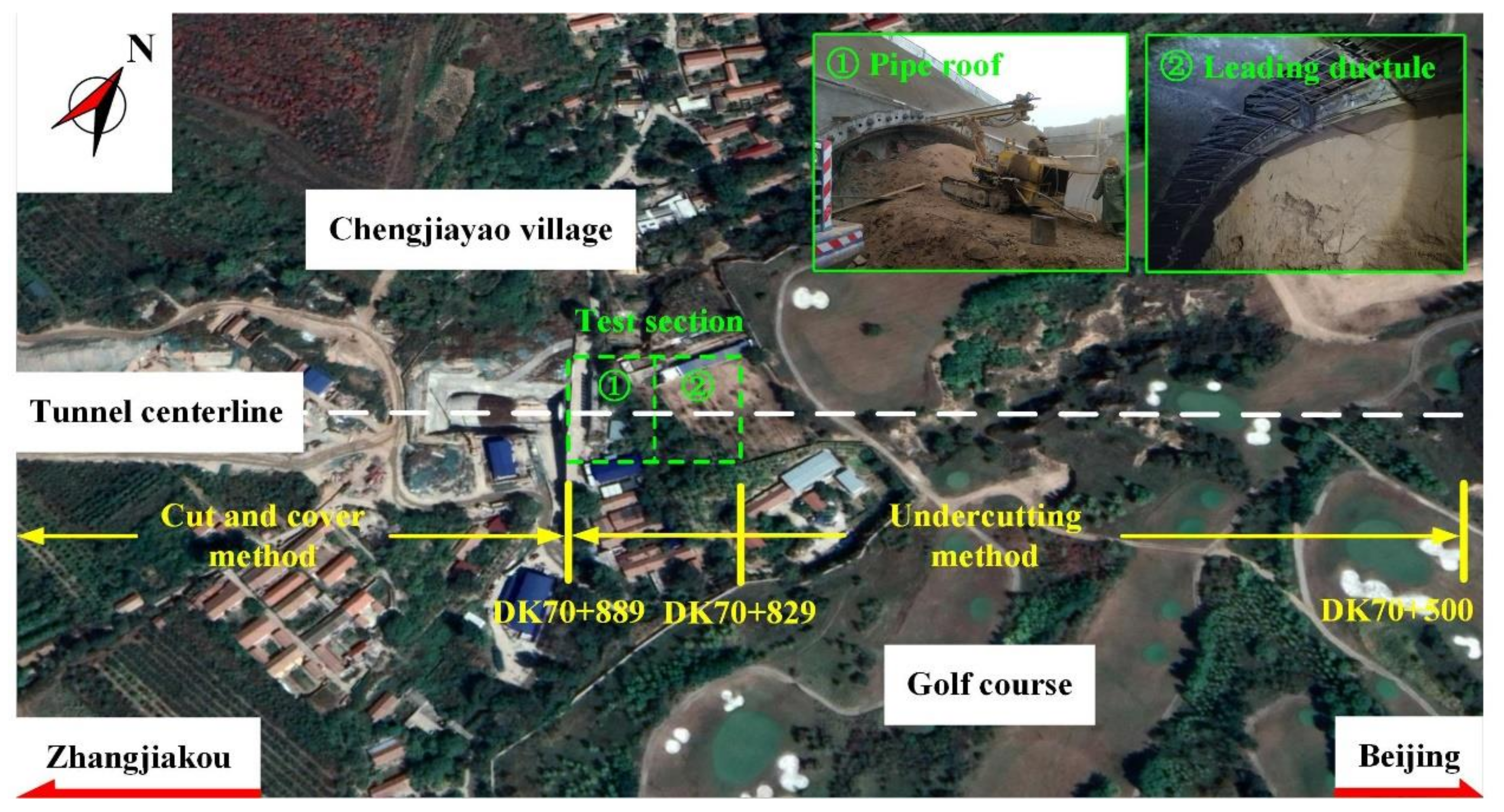
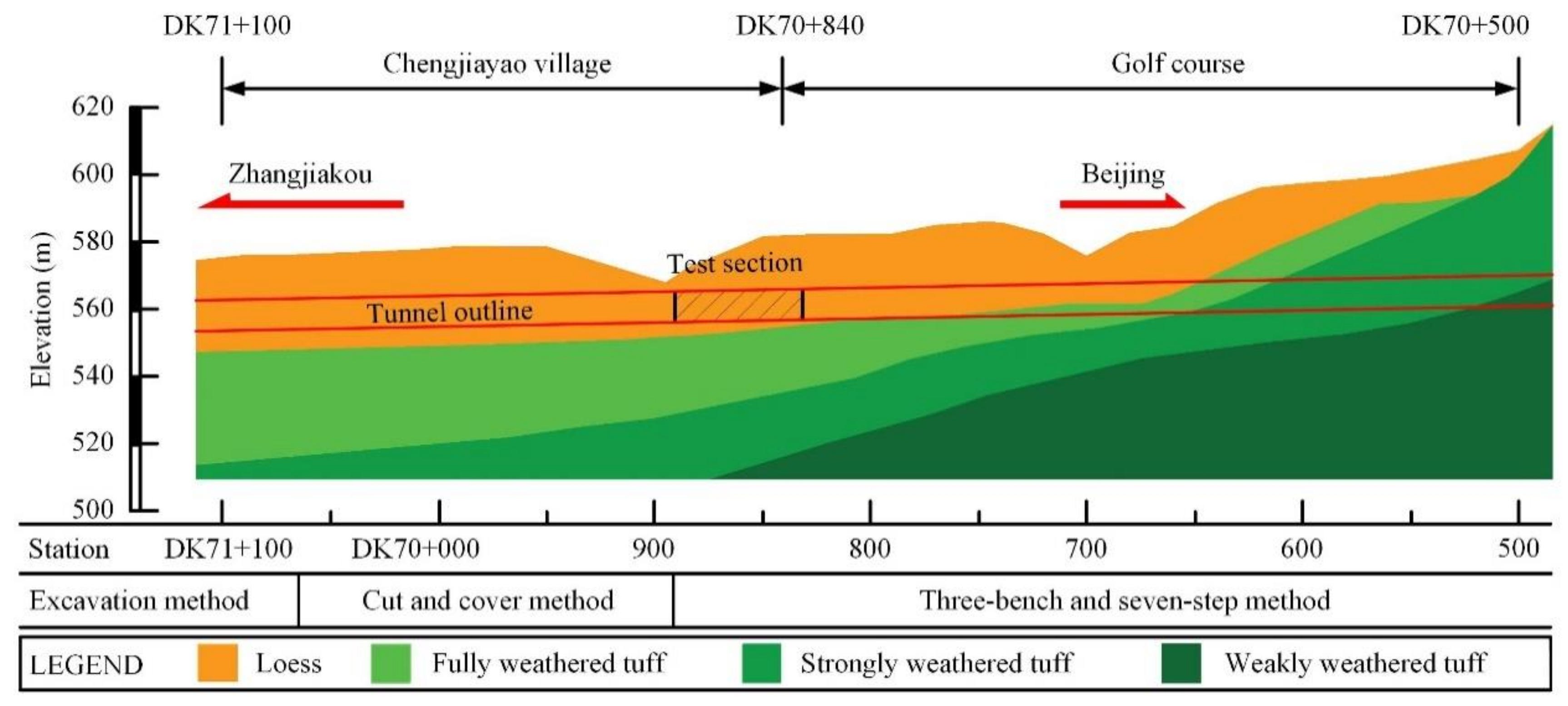
Figure 1). The New Badaling tunnel is a double-track railway tunnel with a total length of around 12 km (from DK59+260 to DK71+270) and a maximum design speed of 250 km/h. It is the longest tunnel with complex construction technology in the Beijing-Zhangjiakou high-speed railway project. Located within the Changping and Yanqing District of Beijing, the New Badaling tunnel passes through the Badaling Great Wall core area. The exit section of the New Badaling tunnel in the direction of Zhangjiakou is buried shallowly with poor ground quality which undercrosses the Chengjiayao Village and a golf course, sequentially (
Figure 2). From DK70+500 to DK70+889, the maximum and minimum buried depth of tunnels are 38 m and 4 m, respectively. The ground is composed of loess with high permeability and poor stability, as well as tuff with diverse weathering degree from the top to the bottom, as shown in
Figure 3.
Table 1 represents the physical and mechanical properties of the exit section of the New Badaling tunnel in the direction of Zhangjiakou. According to the geological prospecting data, ground quality of the surrounding rock is classified as grade V. Tunnel collapses and obvious ground surface settlements easily occur when tunneling in the surrounding rock of grade V. A simplified relationship of the rock mass qualities between the Chinese classification basic quality (BQ) system and the widely used quality (Q) system is listed in
Table 2 [
22].
2.2. Tunnel Design and Construction Scheme
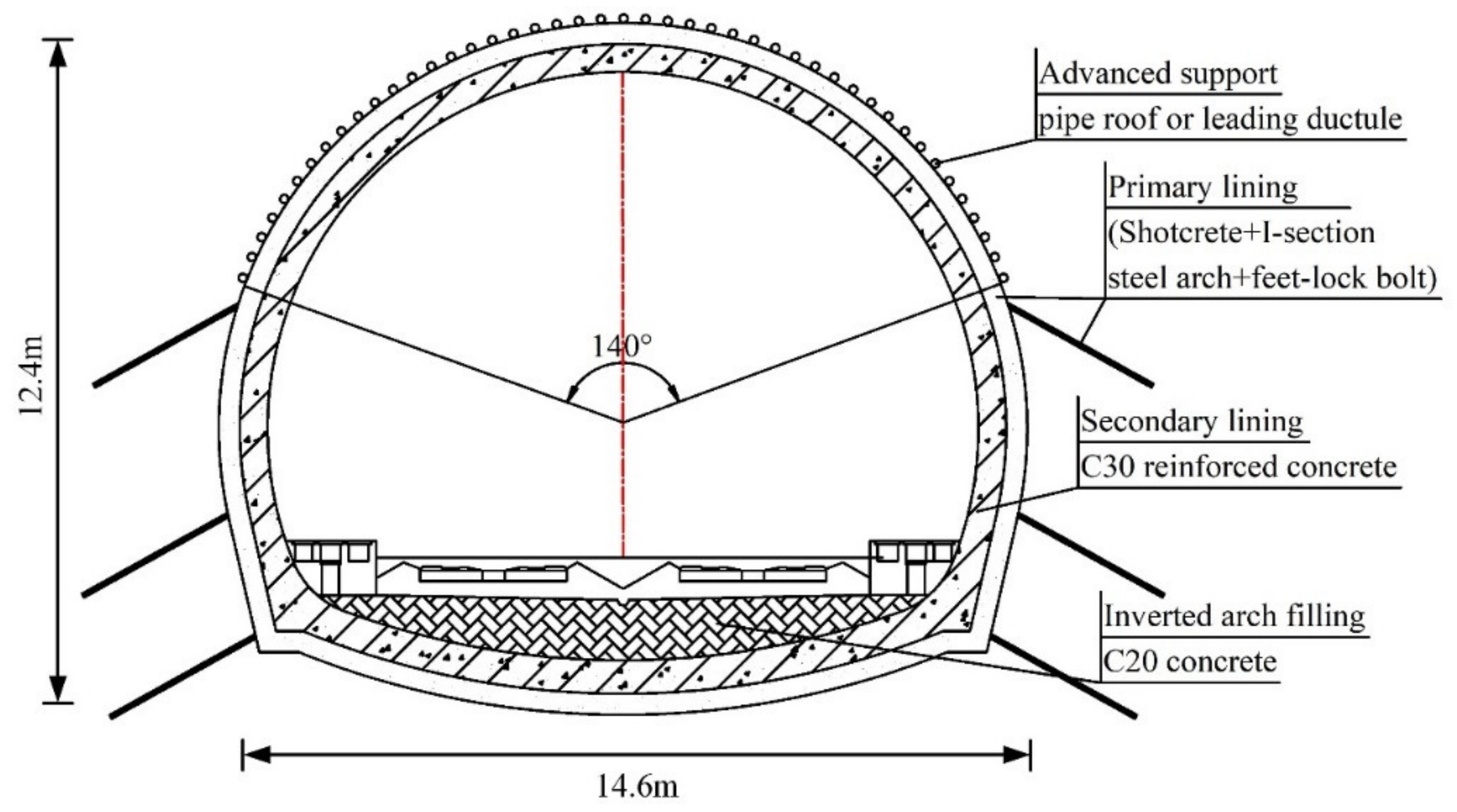
As a large-section loess tunnel, the New Badaling tunnel is a horseshoe-shaped tunnel with a width of 14.78 m, height of 12.49 m and cross-sectional area of 144 m
2. The design parameters of the tunnel support are shown in
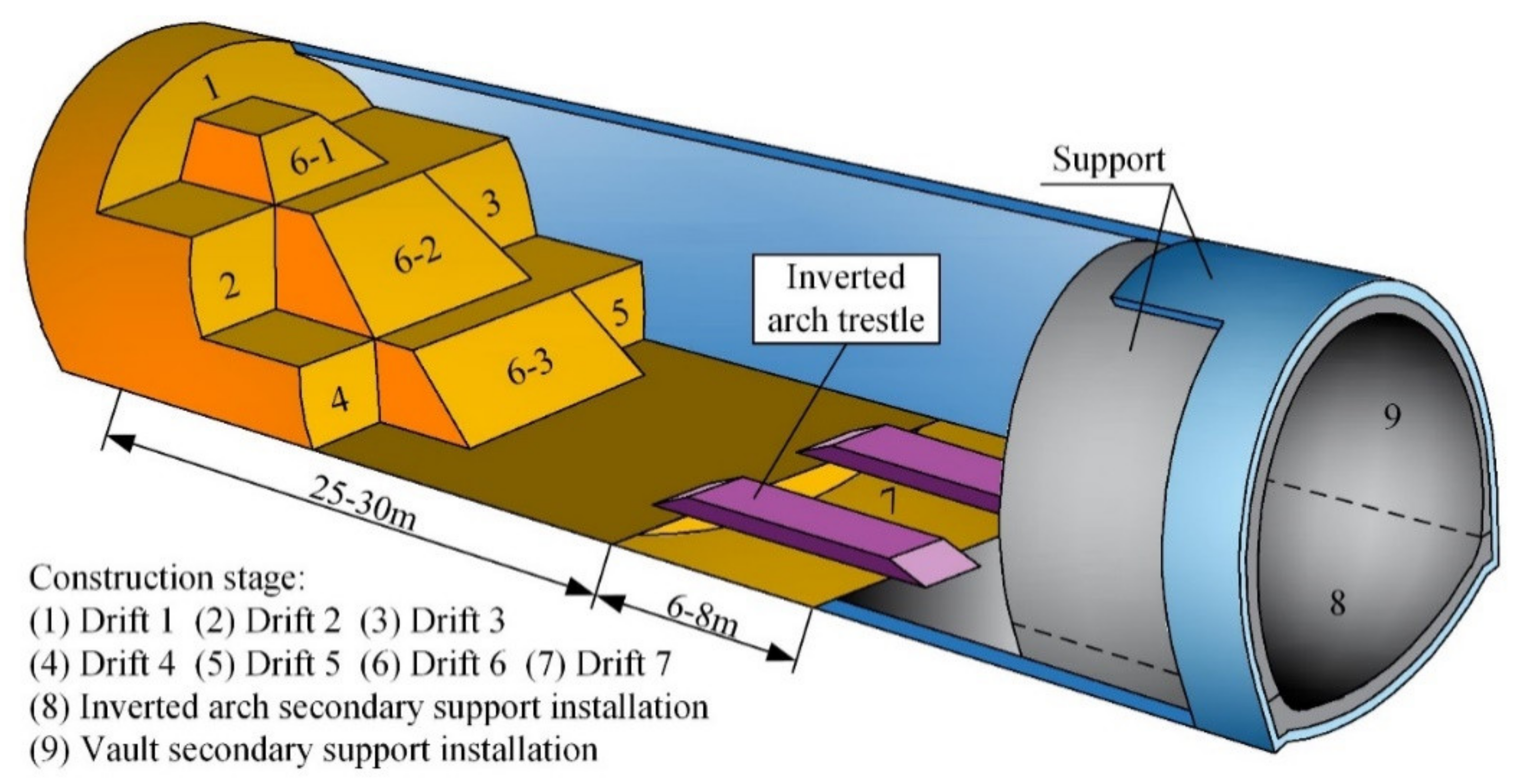
Figure 4. Three-bench seven-step excavation method (TSEM) was used for excavation. The advance length for each step excavation was about 1.6 m, and the distance between two adjacent I-shaped steel sets along the tunnel longitudinal axis was about 0.8 m. A total of nine stages are required to complete the construction of the whole cross-section. In order to avoid the interference of critical disturbance zones on each other, a series of trailing distances between different faces remained. Drift 1, also called upper bench (UB), was excavated first. Middle bench (MB) was composed of drift 2 and drift 3, with a distance of about 2 m. Lower bench (LB) was composed of drift 4 and drift 5, with a distance of about 2 m. Lengths of UB, MB and LB were 3–5 m, 8–13 m, and 8–13 m, respectively. In the excavation of MB and LB, Drift 2 and Drift 4 were excavated with a distance of 2–3 m ahead of Drift 3 and Drift 5, respectively. The secondary support of the whole cross-section was installed in stage 8 and stage 9. Approximately 23 to 28 days were spent closing the primary support to a complete ring, at a distance of about 35 m behind the leading advance face, i.e., the face of drift 1. The distance between the secondary support and the leading advance face was about 60 meters.
Figure 5 demonstrates the specific construction procedure for the project.
2.3. Pre-Support Arrangements
The 60 m test section divided into two parts was set in the exit section of the New Badaling tunnel in the direction of Zhangjiakou, to explore the applicability of various pre-supports within the loess ground, as shown in
Figure 2. From DK70+889 to DK70+859 and from DK70+859 to DK70+829, the pipe roofs and leading ductules were selected as the pre-supports, respectively. Subsequently, the deformation law of tunnel displacements, the GSSs and the effect of ground reinforcement under the two types of pre-supports are discussed. The specific design parameters of the pre-supports are as follows:
(1) Pipe roof
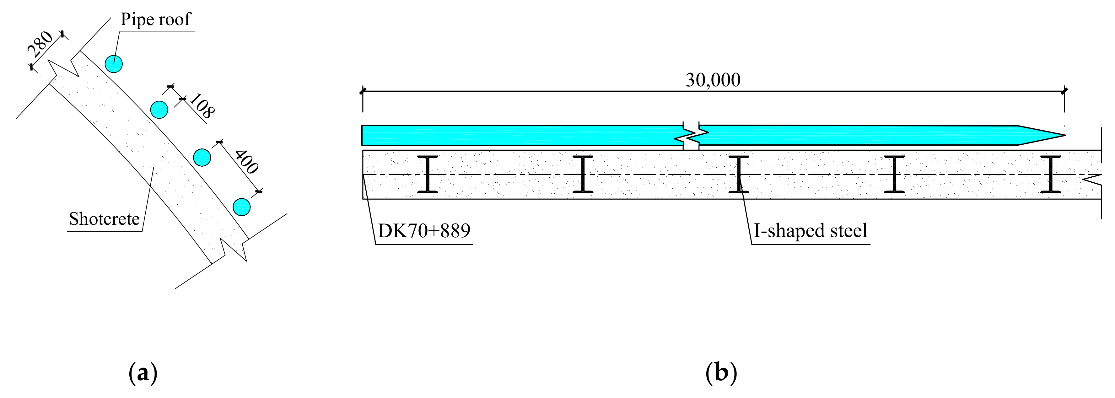
From DK70+889 to DK70+859, 30-m-long pipe roofs were selected as the pre-supports, constructed within 140° of the tunnel arch ahead of the tunnel face. The pipe roofs were composed of φ108 hot-rolled seamless steel pipes, 4–6 m long each and connected by thread. Pipe roofs were installed at an angle of 1° to 3° to the tunnel longitudinal axis, with circumferential space of 40 cm (
Figure 6). Pipe roofs were combined with grouting with a grouting pressure of 0.5–2.0 MPa.
(2) Leading ductule
From DK70+859 to DK70+829, leading ductules with a composition of 4-m-long φ42 hot-rolled seamless steel were adopted as the pre-supports. They were installed at an angle of 10° to 15° to the tunnel longitudinal axis, with the circumferential spacing of 30 cm. A minimum lap length of 1.3 m was considered for the two adjacent rings (
Figure 7). Leading ductules were cooperated by grouting with a grouting pressure of 0.5–1.0 MPa.
2.4. Monitoring Arrangement
Rigidly connected with the primary support, pre-support structure forms a reinforcement circle in the ground. An overall bearing structure of “surrounding rock-pre-support structure-primary support” is composed. The effect of pre-support on loess tunnel can be determined by comparing the primary support displacement and the ground settlement. A total of 12 monitoring sections (from DK70+829 to DK70+887) with the monitoring projects of arch settlement, horizontal convergence, and GSS were arranged as shown in
Table 3 and
Figure 8. As a kind of widely used surveying instrument in tunnel construction, total station has the functions of angle measurement, distance measurement and height difference measurement. Lycra TCRA1102 Total Station with a measuring accuracy of 1 mm was selected as the monitoring instrument. The frequency of data acquisition was 1/24 h, with an acquisition time of 8 to 9 a.m. When the tunnel face reached the monitoring section, GSS and tunnel displacement recording were started. After the tunnel face passed, the monitoring of GSS continued for 10–20 days to ensure the gradual stabilization of GSS. Due to the damage to the monitoring points during the installation of geotextile and waterproof board, the tunnel displacement monitoring work could only be continued until the installation of vault secondary support.
3. Monitoring Results and Analysis
3.1. Tunnel Displacement Characteristics
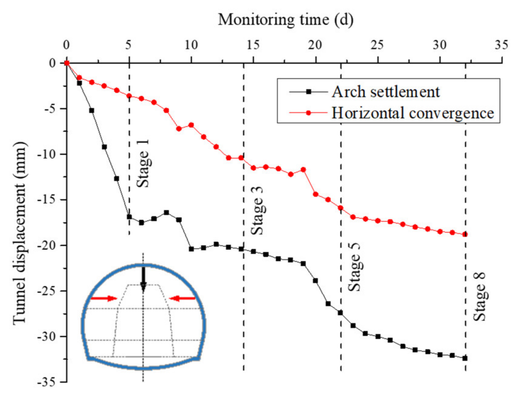
Two representative sections including DK70+829 and DK70+869 in the pipe roof section and the leading ductule section were selected to show the typical tunnel displacement characteristics, including the arch settlement and the horizontal convergence at different construction stages (
Figure 9;
Figure 10). The monitoring results of all monitoring sections are finalized in
Figure 11,
Table 4 and
Table 5. According to the monitoring data, the representative tunnel displacement characteristics of shallow-buried large cross-section loess tunnel are as follows:
(1) The excavation of loess tunnels usually caused significant tunnel displacements. As it can be seen in
Figure 9 and
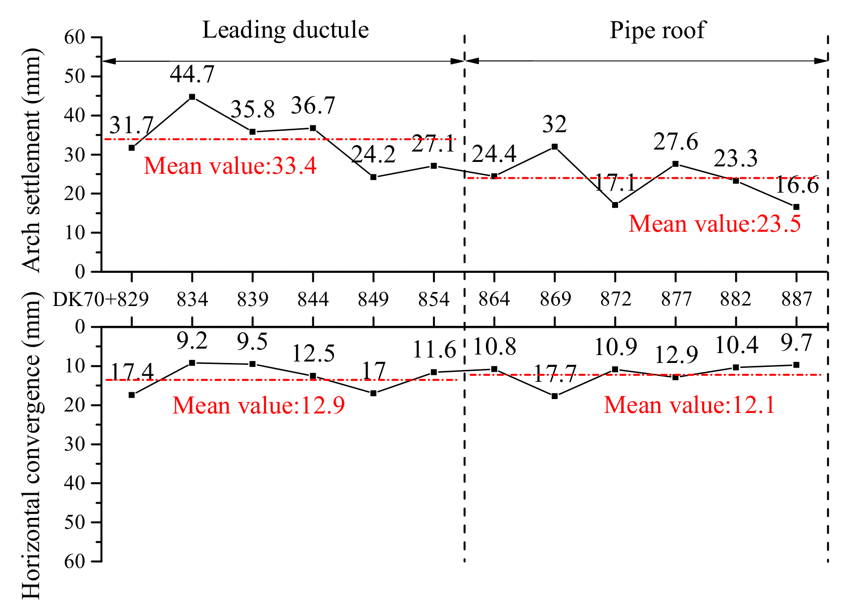
Figure 10, both the arch settlements and horizontal convergences of the section DK70+829 and section DK70+869 were more than 15 mm. Moreover, the maximum value of arch settlement in the concerned zone was 44.7 mm, and the arch settlement rate for more than half of the monitoring sections was more than 3 mm/d. This suggests high deformation potential of the ground, whose release was affected by the excavation of loess tunnel. Therefore, timely supporting can effectively reduce the deformation of surrounding rocks and prevent serious disasters from happening. Moreover, real-time monitoring is also essential and can provide data feedback.
(2) The arch settlement is considered as the dominant displacement induced by tunneling in loess ground. In this case, the distribution range of horizontal convergence for entire monitoring sections was 9.2–17.7 mm, with a significant increase in the distribution range of arch settlement, reaching 16.6–44.7 mm. Moreover, the mean values of arch settlement for the leading ductule sections and the pipe roof sections were 2.6 and 1.9 times the horizontal convergence, respectively. This indicates a clear directional difference of the tunnel displacement in loess ground, hence the arch settlement control is essential to ensure tunnel safety.
(3) A significant difference in the tunnel displacement was identified during the different stages of excavation. According to
Table 4 and
Table 5, the arch settlements at the excavation of stage 1 (UB), stages 2–3 (MB), stages 4–5 (LB), and stages 6–8 accounted for 20.4–56.7, 8.2–65.9, 1.7–24.9, and 3.7–15.0 percentage of the total arch settlement, respectively. The horizontal convergences at the excavation of the mentioned stages were 6.2–77.1%, 2.8–79.4%, 2.3–36.1%, and 0.6–43.5% of the total horizontal convergence, respectively. This suggests that the tunnel displacement was mainly affected by the UB and MB excavation. The highest peak value of the tunnel displacement rate at the excavation of these two benches was identified for the majority of the monitoring sections, indicating quick release of the potential energy of surrounding rocks at the time. Therefore, it is necessary to limit the length of UB and MB and close the primary support in time to achieve a better control on tunnel displacement.
(4) The deformation duration of loess tunnel is long. According to the monitoring data from the horizontal convergence, the continuous convergence of four sections still remained more than 18% of the final value after the excavation of the LB, at the time of day 20–25. The convergence of section DK70+834 even reached up to 44% of the total convergence, after the excavation of the lower bench. Moreover, an increase in the deformation rate of some sections was observed even at the later stage of excavation. It shows that the support structure is bound to bear the increasing load of the surrounding rock for a long time.
3.2. GSS Characteristics
Sections DK70+829 and DK70+869 can also be considered as representative sections to show the development process of the GSSs.
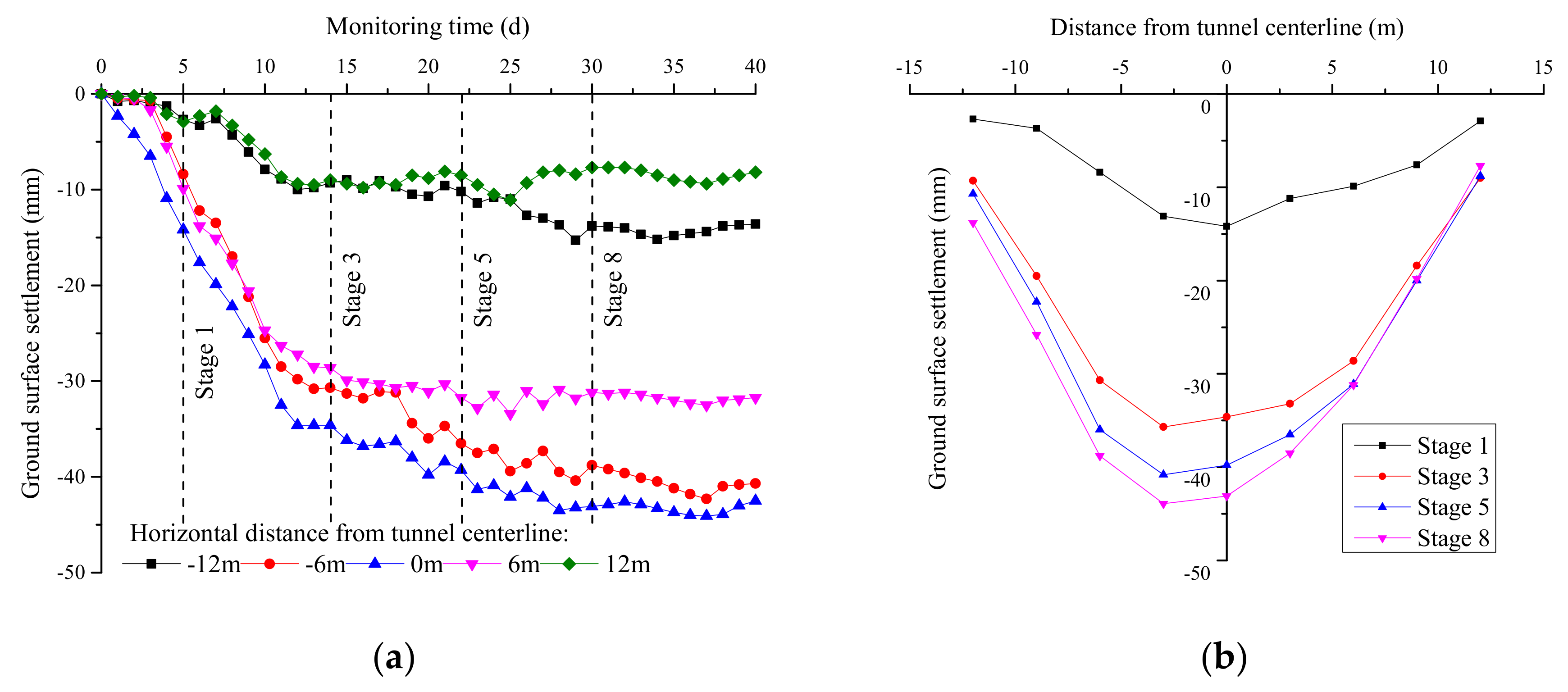
Figure 12 and
Figure 13 represent the GSS trough curves and time curves for different construction stages of these two sections, respectively. The final GSS shape of all monitoring sections is presented in
Figure 14. According to the monitoring data, the GSS characteristics were as follows:
(1) In contrast to the rock tunnels, the GSSs of loess tunnel were more obvious. The GSS above the tunnel centerline of all sections reached 15 mm. In addition, the relatively greater GSS was mainly concentrated in the adjacent area above the tunnel. Reasonable ground reinforcement and support measures in combination with field monitoring could effectively reduce the GSS.
(2) Similar to tunnel displacement, the GSS had a characteristic of process relativity. Indeed, the GSS was mainly caused by UB and MB excavation, which can be identified in
Figure 12 and
Figure 13. After the installation of secondary support, the GSS caused by tunneling could be effectively controlled.
(3) The GSS trough curves were asymmetric. According to
Figure 14, most of the maximum points of the GSS trough curves were distributed on the left-hand side of the tunnel centerline. On the left-hand side of the maximum point, narrower GSS trough curves with larger slopes than the other side were identified. The specific evolution processes of the GSS trough curves can be seen in
Figure 12b and
Figure 13b. In the excavation of MB and LB, the ground settlements caused by the early excavation side were greater than those caused by the later excavation side. It is because the ground deformation time caused by previous step is relatively longer than that caused by the following step. Therefore, the GSS trough curves deviated to the early excavation side, with no conformation to the Gauss distribution.
3.3. Comparison of Tunnel Displacement with Different Pre-Supports
For the leading ductule section, the distribution ranges of the arch settlement and horizontal convergence were about 24–45 mm and 9–20 mm, respectively. Moreover, the mean values were calculated as around 33 mm and 13 mm, respectively. Whereas, the distribution ranges of the arch settlement and the horizontal convergence in the pipe roof section were circa 17–31 mm and 10–18 mm, respectively, with mean values of 23 mm and 12 mm, correspondingly (
Figure 11). When the leading ductule was used as pre-support, the arch settlement and horizontal convergence in the leading ductule section were increased to different degrees compared to those in the pipe roof section, and a clearer increase of the arch settlement was observed. This suggests that for shallow-buried large cross-section loess tunnel, a better control on the arch settlement can be achieved through the pipe roof, in comparison with the leading ductule.
The proportion of the tunnel displacement at each excavation stage in the total tunnel displacement is presented in
Table 4 and
Table 5. The requirements of TSEM were strictly followed in the excavation of each section. Therefore, the tunnel displacement proportion at different excavation stages can reflect the ground response at each excavation stage. In this regard, the excavation stage with the largest tunnel displacement proportion was defined as the maximum deformation stage. The maximum arch settlement stage and the maximum horizontal convergence stage of all monitoring sections were calculated, as shown in
Figure 15. The maximum arch settlement stages within the pipe roof sections and the leading ductule sections are UB with four monitoring sections and MB stages with five monitoring sections, respectively. The ground response time of the pipe roof section was earlier than that of the leading ductule section. However, no obvious difference in the horizontal convergence was observed in regard to this phenomenon. This suggests that the pipe roof had greater disturbance to the ground outside the reinforcement ring when it reinforced the ground in advance. This was mainly reflected vertically, rather than horizontally. This is due to the setting of the pipe roof and the leading ductule outside the arch, hence the disturbance was mostly concentrated in the ground above the arch, and less disturbance occurred within the ground on the side of the tunnel.
3.4. Comparison of GSS with Different Pre-Supports
Section DK70+829 with a buried depth of 16 m and section DK70+869 with a buried depth of 12.4 m were selected as the representative sections for the pipe roof and the leading ductule sections. The arch settlement, horizontal convergence, and GSS at the tunnel centerline of section DK70+829 were 31.7 mm, 17.4 mm, and 43.1 mm, respectively. These corresponding results for section DK70+869 were 32 mm, 17.7 mm, and 43.2 mm, respectively. Comparing the results, it can be concluded that the arch settlement and the GSS at the tunnel centerline of section DK70+869 were slightly larger than these values for section DK70+829. The GSS values at the tunnel centerline were almost equal in the two sections, while the buried depth of section DK70+869 was less than that of the DK70+829 section. According to stochastic medium theory [
23], for unlined shallow-buried tunnel, the GSS at the tunnel centerline is positively correlated with tunnel displacement, while it is negatively correlated with the tunnel buried depth. This suggests that the reinforcement circle formed by the pipe roof provides a greater effect on hindering the deformation development of the upper ground.
4. Conclusions
This paper comprehensively presents an analysis of tunnel displacements and ground surface settlements during the construction of a large-section loess tunnel. Representative sections using pipe roofs and leading ductules as pre-supports are investigated, based on which the effects of the two pre-supports are compared. The main findings of this research are as follows:
(1) Significant tunnel displacements occurred during the excavation of large-section loess tunnel. The monitoring results suggested the tunnel displacements were related to the construction process and space position, which were mainly concentrated in the excavation stage of the upper bench and middle bench. However, some differences in the proportion of the arch settlement and horizontal convergence were identified in the excavation stage of the upper bench and middle bench, suggesting a proportion of 20.4–56.7%, 8.2–65.9% and 6.2–77.1%, 2.8–79.4% respectively.
(2) During the excavation process, tunnel deformation lasts for a long time, and the influence of excavation of the lower bench and the inverted arch on tunnel displacement should not be ignored. A high proportion of tunnel displacements, including the arch settlements and horizontal convergences, were identified in some monitoring sections, reaching up to around 20%. This explains the necessity of monitoring the tunnel displacement during the entire process.
(3) The ground surface settlement trough in the concerned zone excavated by three-bench seven-step excavation method is no longer symmetric, with respect to the tunnel centerline. In the excavation of the middle bench and lower bench, the ground settlements caused by the early excavation side were larger than those caused by the later excavation side. Therefore, the ground settlement trough curves were deviated to the early excavation side, with no adjustment to the Gauss distribution.
(4) A comprehensive comparison of the results of tunnel displacement and ground surface settlement in the pipe roof section and the leading ductule section suggests that the effect of pipe roof on the ground reinforcement was better, particularly in the control of arch settlement. The mean value of the arch settlements in the leading ductule section was reduced from 33.4 mm to 23.5 mm compared to the pipe roof section. The pipe roof had greater disturbance to the soil outside the reinforcement ring when reinforcing the ground in advance, which caused earlier ground response.
Author Contributions
Conceptualization, D.L. and D.Z.; Data curation, D.L. and Q.F.; Formal analysis, D.L. and L.C.; Investigation, D.L. and A.L.; Methodology, D.L. and Q.F.; Validation, D.L. and D.Z.; Writing—Original draft preparation, D.L.; Writing—Review & editing, D.L. and Z.S. All authors have read and agreed to the published version of the manuscript.
Funding
This research was funded by National Key Research and Development Programs of China, grant number 2017YFC0805401 and Chinese National Natural Science Foundation, grant number 51678035.
Conflicts of Interest
The authors declare no conflict of interest. The funders had no role in the design of the study; in the collection, analyses, or interpretation of data; in the writing of the manuscript, or in the decision to publish the results.
References
- Tonon, F. ADECO full-face tunnel excavation of two 260 m (2) tubes in clays with sub-horizontal jet-grouting under minimal urban cover. Tunn. Undergr. Space Technol. 2011, 26, 253–266. [Google Scholar] [CrossRef]
- Lisjak, A.; Garitte, B.; Grasselli, G. The excavation of a circular tunnel in a bedded argillaceous rock (Opalinus Clay): Short-term rock mass response and FDEM numerical analysis. Tunn. Undergr. Space Technol. 2015, 45, 227–248. [Google Scholar] [CrossRef]
- Li, P.F.; Zhao, Y.; Zhou, X.J. Displacement characteristics of high-speed railway tunnel construction in loess ground by using multi-step excavation method. Tunn. Undergr. Space Technol. 2016, 51, 41–55. [Google Scholar] [CrossRef]
- Hu, Z.; Du, K.; Lai, J.X.; Xie, Y.L. Statistical analysis of influence of cover depth on loess tunnel deformation in NW China. Adv. Civ. Eng. 2019, 2019, 2706976. [Google Scholar] [CrossRef]
- Liu, X.; Fang, Q.; Zhang, D.L.; Liu, Y. Energy-based prediction of volume loss ratio and plastic zone dimension of shallow tunneling. Comput. Geotech. 2020, 118, 103343. [Google Scholar] [CrossRef]
- Salmi, E.F.; Nazem, M.; Giacomini, A. A numerical investigation of sinkhole subsidence development over shallow excavations in tectonised weak rocks: The dolaei tunnel’s excavation case. Geotech. Geol. Eng. 2017, 35, 1685–1716. [Google Scholar] [CrossRef]
- Elyasi, A.; Moradi, T.; Moharrami, J.; Parnian, S.; Mousazadeh, A.; Nasseh, S. Efficiency assessment of l-profiles and pipe fore-poling pre- support systems in difficult geological conditions: A case study. Struct. Eng. Mech. 2016, 57, 1125–1142. [Google Scholar] [CrossRef]
- Aksoy, C.O.; Onargan, T. The role of umbrella arch and face bolt as deformation preventing support system in preventing building damages. Tunn. Undergr. Space Technol. 2010, 25, 553–559. [Google Scholar] [CrossRef]
- Majcherczyk, T.; Niedbalski, Z.; Kowalski, M. 3D numerical modeling of road tunnel stability-The Laliki project/Modelowanie 3D DLA oceny stateczności tunelu drogowego w Lalikach. Arch. Min. Sci. 2012, 57, 61–78. [Google Scholar] [CrossRef]
- Shin, J.H.; Choi, Y.K.; Kwon, O.Y.; Lee, S.D. Model testing for pipe-reinforced tunnel heading in a granular soil. Tunn. Undergr. Space Technol. 2008, 23, 241–250. [Google Scholar] [CrossRef]
- Ocak, I. Control of surface settlements with umbrella arch method in second stage excavations of istanbul metro. Tunn. Undergr. Space Technol. 2008, 23, 674–681. [Google Scholar] [CrossRef]
- Yasitli, N.E. Numerical modeling of surface settlements at the transition zone excavated by new austrian tunneling method and umbrella arch method in weak rock. Arab. J. Geosci. 2013, 6, 2699–2708. [Google Scholar] [CrossRef]
- Zhang, Z.Q.; Li, H.Y.; Liu, H.Y.; Li, G.J.; Shi, X.Q. Load transferring mechanism of pipe umbrella support in shallow-buried tunnels. Tunn. Undergr. Space Technol. 2014, 43, 213–221. [Google Scholar] [CrossRef]
- Bae, G.J.; Shin, H.S.; Sicilia, C.; Choi, Y.G.; Lim, J.J. Homogenization framework for three-dimensional elastoplastic finite element analysis of a grouted pipe-roofing reinforcement method for tunnelling. Int. J. Numer. Anal. Methods Geomech. 2005, 29, 1–24. [Google Scholar] [CrossRef]
- Hu, X.D.; Deng, S.J.; Ren, H. In situ test study on freezing scheme of freeze-sealing pipe roof applied to the gongbei tunnel in the hong kong-zhuhai-macau bridge. Appl. Sci. 2016, 7, 27. [Google Scholar] [CrossRef]
- Hasanpour, R.; Chakeri, H.; Ozcelik, Y.; Denek, H. Evaluation of surface settlements in the Istanbul metro in terms of analytical, numerical and direct measurements. Bull. Eng. Geol. Environ. 2012, 71, 499–510. [Google Scholar] [CrossRef]
- Wu, K.; Shao, Z.S. Effects of pipe roof support and grouting pre-reinforcement on the track settlement. Adv. Civil. Eng. 2018, 2018, 6041305. [Google Scholar] [CrossRef]
- Xie, X.Y.; Zhao, M.R.; Shahrour, I. Experimental study of the behavior of rectangular excavations supported by a pipe roof. Appl. Sci. 2019, 9, 2082. [Google Scholar] [CrossRef]
- Wang, Z.C.; Li, W.; Li, S.C.; Qiu, W.G.; Ding, W.T. Development of an Optimum Forepole Spacing (OFS) determination method for tunnelling in silty clay with a case study. Tunn. Undergr. Space Technol. 2018, 74, 20–32. [Google Scholar] [CrossRef]
- Zarei, H.; Moarefvand, P.; Salmi, E.F. Numerical modeling of umbrella arch technique to reduce tunnelling induced ground movements. Environ. Earth Sci. 2019, 78, 291. [Google Scholar] [CrossRef]
- Divall, S.; Taylor, R.N.; Xu, M. Centrifuge modelling of tunnelling with forepoling. Int. J. Phys. Model. Geotech. 2015, 16, 83–95. [Google Scholar] [CrossRef]
- Zhang, D.L.; Fang, Q.; Hou, Y.J.; Wong, L.N.Y. Protection of buildings against damages as a result of adjacent large-span tunneling in shallowly buried soft ground. J. Geotech. Geoenviron. Eng. 2013, 139, 903–913. [Google Scholar] [CrossRef]
- Yang, J.S.; Liu, B.C.; Wang, M.C. Modeling of tunneling-induced ground surface movements using stochastic medium theory. Tunn. Undergr. Space Technol. 2004, 19, 113–123. [Google Scholar] [CrossRef]
Figure 1.
Map of Beijing-Zhangjiakou high-speed railway.
Figure 1.
Map of Beijing-Zhangjiakou high-speed railway.
Figure 2.
Aerial photo of the project area.
Figure 2.
Aerial photo of the project area.
Figure 3.
Longitudinal geological profile of northwest portal of New Badaling tunnel.
Figure 3.
Longitudinal geological profile of northwest portal of New Badaling tunnel.
Figure 4.
Support parameters of New Badaling tunnel.
Figure 4.
Support parameters of New Badaling tunnel.
Figure 5.
Longitudinal perspective of three-bench seven-step excavation method.
Figure 5.
Longitudinal perspective of three-bench seven-step excavation method.
Figure 6.
Schematic image of the pipe roof (unit: mm): (a) Cross section; (b) Longitudinal section.
Figure 6.
Schematic image of the pipe roof (unit: mm): (a) Cross section; (b) Longitudinal section.
Figure 7.
Schematic image of the leading ductule (unit: mm): (a) Cross section; (b) Longitudinal section.
Figure 7.
Schematic image of the leading ductule (unit: mm): (a) Cross section; (b) Longitudinal section.
Figure 8.
Layout of the monitoring points of monitoring sections.
Figure 8.
Layout of the monitoring points of monitoring sections.
Figure 9.
Tunnel displacement–time curves of section DK70+829.
Figure 9.
Tunnel displacement–time curves of section DK70+829.
Figure 10.
Tunnel displacement–time curves of section DK70+869.
Figure 10.
Tunnel displacement–time curves of section DK70+869.
Figure 11.
Final monitoring values of tunnel displacement.
Figure 11.
Final monitoring values of tunnel displacement.
Figure 12.
Surface settlements monitoring results of section DK70+829: (a) Development of GSSs; (b) Surface settlement troughs of typical excavation stages.
Figure 12.
Surface settlements monitoring results of section DK70+829: (a) Development of GSSs; (b) Surface settlement troughs of typical excavation stages.
Figure 13.
Surface settlements monitoring results of section DK70+869: (a) Development of GSSs; (b) Surface settlement troughs of typical excavation stages.
Figure 13.
Surface settlements monitoring results of section DK70+869: (a) Development of GSSs; (b) Surface settlement troughs of typical excavation stages.
Figure 14.
Final surface settlement troughs of each section.
Figure 14.
Final surface settlement troughs of each section.
Figure 15.
Distribution of maximum arch settlement and horizontal convergence stage in all monitoring sections.
Figure 15.
Distribution of maximum arch settlement and horizontal convergence stage in all monitoring sections.
Table 1.
The typical physical and mechanical properties of ground.
Table 1.
The typical physical and mechanical properties of ground.
| | Specific Weight
(kN/m3) | Elastic Modulus
(GPa) | Poisson’s Ratio | Cohesion
(kPa) | Friction Angle(°) |
|---|
| loess | 17.6 | 0.1 | 0.37 | 25 | 27.3 |
| fully weathered tuff | 26.7 | 3.5 | - | 165 | 31.3 |
| strongly weathered tuff | 27.0 | 11.3 | 0.3 | 750 | 40.2 |
| weakly weathered tuff | 27.1 | 33.1 | 0.23 | 1850 | 50.6 |
Table 2.
Relationship between the basic quality (BQ) system and quality (Q) System.
Table 2.
Relationship between the basic quality (BQ) system and quality (Q) System.
| | Grade I | Grade II | Grade III | Grade IV | Grade V |
|---|
| Value | (Very Good) | (Good) | (Fair) | (Poor) | (Very Poor) |
|---|
| BQ | >550 | 451–550 | 351–450 | 251–350 | <250 |
| Q | >40 | 10–40 | 4–10 | 1–4 | <1 |
Table 3.
Monitoring procedures of each section.
Table 3.
Monitoring procedures of each section.
Monitoring
Section | Pre-Support
Type | Buried Depth
(m) | Arch
Settlement | Horizontal
Convergence | Ground Surface
Settlement |
|---|
| DK70+829 | leading
ductule | 16 | ★ | ★ | ★ |
| DK70+834 | 16 | ★ | ★ | |
| DK70+839 | 16 | ★ | ★ | ★ |
| DK70+844 | 16 | ★ | ★ | |
| DK70+849 | 16 | ★ | ★ | ★ |
| DK70+854 | 16 | ★ | ★ | |
| DK70+864 | pipe roof | 12.4 | ★ | ★ |
| DK70+869 | 12.4 | ★ | ★ | ★ |
| DK70+872 | 11.3 | ★ | ★ |
| DK70+877 | 11.1 | ★ | ★ | ★ |
| DK70+882 | 6.2 | ★ | ★ | ★ |
| DK70+887 | 2.1 | ★ | ★ | |
Table 4.
Settlement proportion and maximum settlement rate.
Table 4.
Settlement proportion and maximum settlement rate.
Monitoring
Section | Pre-Support
Type | Buried
Depth
(m) | Settlement Proportion/% | Maximum
Settlement Rate (mm/d) |
|---|
Stage
1 | Stage
2–3 | Stage
4–5 | Stage
6–8 | Stage
1 | Stage
2–3 | Stage
4–5 | Stage
6–8 |
|---|
| DK70+829 | leading
ductule | 16 | 53.3 | 8.2 | 24.9 | 13.6 | 4.2 | 3.2 | 2.5 | 1.4 |
| DK70+834 | 16 | 28.2 | 41.2 | 15.7 | 15.0 | 3.5 | 2.6 | 1.9 | 1.4 |
| DK70+839 | 16 | 34.6 | 49.4 | 3.6 | 12.3 | 3.9 | 4.1 | 0.9 | 1.6 |
| DK70+844 | 16 | 20.4 | 65.9 | 3.0 | 10.6 | 2.7 | 3.7 | 1.7 | 1.2 |
| DK70+849 | 16 | 31.4 | 47.5 | 16.5 | 3.7 | 2 | 2.4 | 1.2 | 0.8 |
| DK70+854 | 16 | 33.6 | 48.7 | 12.5 | 5.2 | 2.7 | 3.7 | 0.9 | 1.4 |
| DK70+864 | pipe
roof | 12.4 | 23.8 | 53.3 | 13.1 | 9.8 | 2.4 | 2.8 | 2.3 | 1.1 |
| DK70+869 | 12.4 | 34.1 | 30.9 | 20.9 | 14.1 | 2.3 | 2.7 | 2.8 | 0.7 |
| DK70+872 | 11.3 | 54.4 | 22.2 | 18.1 | 5.3 | 3.8 | 1.1 | 1.7 | 0.5 |
| DK70+877 | 11.1 | 45.3 | 42.4 | 7.6 | 4.7 | 4 | 2.5 | 1.3 | 0.7 |
| DK70+882 | 6.2 | 56.7 | 33.5 | 1.7 | 8.2 | 4.1 | 1.7 | 0.8 | 0.6 |
| DK70+887 | 2.1 | 34.9 | 50.0 | 3.6 | 11.4 | 3.1 | 3.7 | 0.7 | 0.4 |
Table 5.
Convergence proportion and maximum convergence rate.
Table 5.
Convergence proportion and maximum convergence rate.
Monitoring
Section | Pre-Support
Type | Buried
Depth
(m) | Convergence Proportion/% | Maximum
Convergence Rate (mm/d) |
|---|
Stage
1 | Stage
2–3 | Stage
4–5 | Stage
6–8 | Stage
1 | Stage
2–3 | Stage
4–5 | Stage
6–8 |
|---|
| DK70+829 | Leading
ductule | 16 | 20.7 | 39.1 | 31.6 | 8.6 | 1.6 | 2 | 2.7 | 0.3 |
| DK70+834 | 16 | 22.8 | 22.8 | 10.9 | 43.5 | 1.6 | 1.9 | 1.4 | 1.8 |
| DK70+839 | 16 | 40.0 | 29.5 | 28.4 | 2.1 | 3.6 | 2.2 | 0.9 | 0.8 |
| DK70+844 | 16 | 56.8 | 13.6 | 11.2 | 18.4 | 2.1 | 1.2 | 1.4 | 0.7 |
| DK70+849 | 16 | 40.6 | 31.8 | 4.1 | 23.5 | 1.8 | 2.5 | 0.4 | 1.4 |
| DK70+854 | 16 | 25.5 | 50.3 | 23.6 | 0.6 | 1 | 1.2 | 1 | 0.4 |
| DK70+864 | Pipe
roof | 12.4 | 51.9 | 2.8 | 36.1 | 9.3 | 2.1 | 1.3 | 2.8 | 0.7 |
| DK70+869 | 12.4 | 32.8 | 38.4 | 5.6 | 23.2 | 1.7 | 2.2 | 0.8 | 1.3 |
| DK70+872 | 11.3 | 77.1 | 17.4 | 2.8 | 2.8 | 2.8 | 1.4 | 0.8 | 0.8 |
| DK70+877 | 11.1 | 65.1 | 31.0 | 2.3 | 1.6 | 2.2 | 2.2 | 1.4 | 0.7 |
| DK70+882 | 6.2 | 42.3 | 40.4 | 7.7 | 9.6 | 2.3 | 1.2 | 0.8 | 0.5 |
| DK70+887 | 2.1 | 6.2 | 79.4 | 4.1 | 10.3 | 0.6 | 2.3 | 1 | 0.7 |
© 2019 by the authors. Licensee MDPI, Basel, Switzerland. This article is an open access article distributed under the terms and conditions of the Creative Commons Attribution (CC BY) license (http://creativecommons.org/licenses/by/4.0/).


