1. Introduction
National and international standards have been adapted for manufacturing of 154 kV insulators, specifying the electrical and mechanical performance requirements that the insulators must meet. Size, insulation, electrical and mechanical strength are important for service compatibility in various countries. The design and material of a porcelain insulator varies according to the processing method. American National Standards Institute (ANSI) and the Canadian Standards Association (CSA) worked hard to reconcile these variations, and after a considerable time, the International Electrochemical Commission (IEC) standard achieved consensus and was accepted commercially all over the world [
1,
2]. This study aims to investigate the effects of aging on porcelain insulators and provide guidelines for the diagnosis of the extent of damage caused by aging within metal and cement. At present, the lifespan of a porcelain insulator device is predicted to be from 30 to 60 years or more [
3]. Once such an insulator is installed and ready for use, it should be able to serve the customer without interruption. It is very difficult to replace all the insulators on a line at once because of safety concerns. Currently, replacement is only carried out if external damage is visible. Since we cannot accurately predict the life expectancy of the porcelain insulator, it is necessary to instead track age-related changes in the porcelain structure. As data from aging studies accumulate, life expectancy may become predictable.
The lifespan of insulators varies considerably. From an electrical point of view, there should be no arc discharge, and sound insulation properties are required to withstand transient voltages such as lightning. Robust mechanical properties are required due to weather conditions such as wind, ice, snow, and rain [
4]. The porcelain insulator is not a single structure of uniform construction, but a complex structure of iron, cement, and ceramics. Deterioration of characteristics after a long period of use require diagnosis of aging [
5].
If the electrical characteristics deteriorate, it leads to partial discharge or flashover, which means the insulator can no longer insulate effectively. If the mechanical characteristics deteriorate, the insulator cannot be used in the transmission tower, posing the risk of a serious accident. This is due to environmental degradation caused by various pollutants including water, and both electrical and mechanical stress [
6].
Investigation has been carried out in order to analyze the degradation of cement by implementing three-dimensional computed tomography (3D-CT), which has a very high resolution and is considered a non-destructive way to analyze the deterioration due to internal defects. When applied to the analysis of porcelain insulators, 3D-CT is particularly useful in detecting degradation of the cement component. Clinker, which is the main component of cement used for porcelain insulators, consists of alite (3CaOSiO
2), belite (CaOSiO
2), aluminate (NaAlO
2), and ferrite (Fe
2O
3). Alite and belite hydrate produce low-crystalline calcium silicate hydrate gel (C-S-H gel) and Ca(OH)
2 [
7]. The chemical composition and crystallinity of C-S-H gel varies during the hydration process. Immediately after the hydration reaction, the pH is raised to 10 or more due to the intrusion of H
2O and the separation of Ca
2+ ions. The low C-S layer is formed on the surface, and as time passes, the Ca
2+ ion concentration increases and the hydrate layer thickens, and then the rehydration reaction occurs and the crystal growth proceeds.
When the aluminate and ferrite crystal phases react with water, rapid hydration heat occurs and they stabilize to C
4AH
19 and C
2AH
8 hydrate. After a period of time elapses, they hydrate to stable C
3AH
6. Therefore, gypsum is added to generate ettringite hydrate and achieve hydration using C
3A hydrate [
8].
2. Single-Layer Analysis of Porcelain Insulator Using Three Dimensional-Computed Tomography
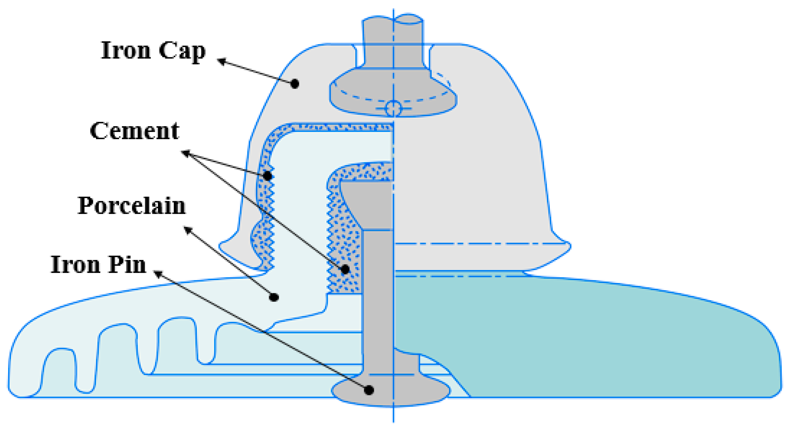
The porcelain insulator for 154 kV power transmission, shown in
Figure 1, has been in use since the 1950s. It is composed of an iron cap, cement, an iron pin, and porcelain material with a diameter of 250 mm [
9].
The iron cap and iron pin are coated with zinc, which is widely used for corrosion prevention in industry. This paper focusses on the analysis of deterioration characteristics and deterioration mechanisms of aged insulators, with particular focus on the deterioration of metal and cement, as porcelain itself undergoes the least change. According to USASI (United States of America Standards Institute) 29.2 the components of porcelain insulators experience mechanical damage in the order of iron pin, iron cap, porcelain [
10].
However, since the cement part acts as a bridge connecting all the constituents of the porcelain insulator, the mechanical property guarantee is very important, especially when the components are exposed to the actual service environment [
11]. The risk of accidents increases as the deterioration of the cement progresses, making it difficult to maintain the characteristics of the insulator. This study mainly focuses on the reason for the corrosion and degradation of the metal and cement parts of porcelain insulators, and what happens when deterioration progresses.
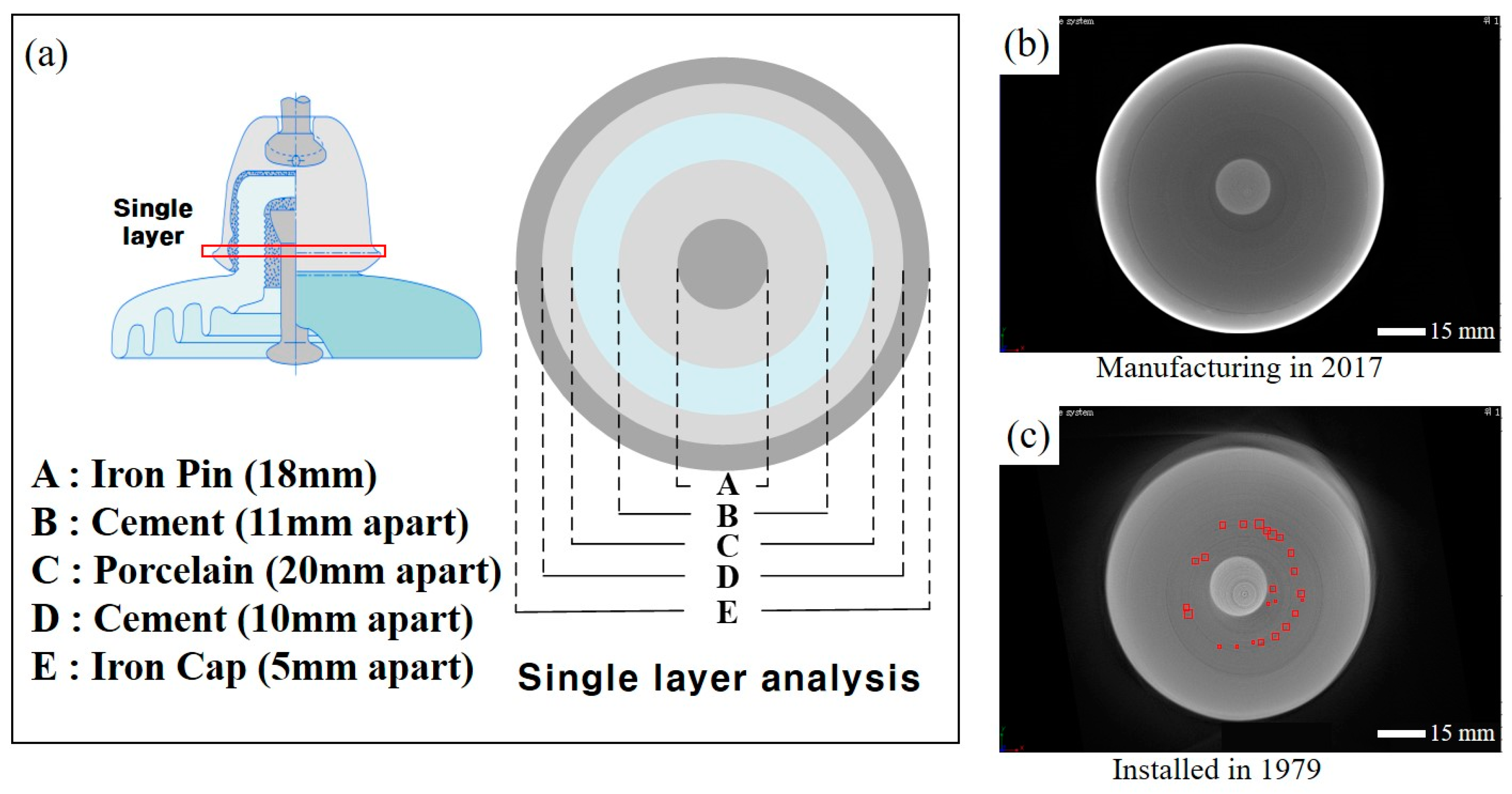
Figure 2a shows the 3D-CT analysis of the single layer.
Figure 2b shows a new product that was manufactured in 2017 and has never been in service, a small air pocket of less than 3 mm
2 appears inside, but this can occur during the curing process of the cement. The insulator shown in
Figure 2c has been in use for 38 years from 1979 to 2017; the 3D-CT analysis revealed more than 20 pores with sizes of more than 3 mm
2 inside the cement. In the case of porcelain insulators produced in 2017, pores smaller than 3 mm
2 occur in the curing process, and in the case of porcelain insulators installed in 1979, pores larger than 14 mm
2 are increased by the alkali-silica reaction (ASR) reaction. In the case of porcelain insulators that have been used for a long time, the cement degradation and the size of the pores increases.
This is because the silica and alkali components in the cement react with water to form alkali-silica gel, and the gel reacts with water to cause expansion of the cement, and thereby, cracking. This reaction is called an alkali-silica reaction (ASR). In general, a pH of higher than 12, moisture, and reactive silica are required to generate an ASR reaction in the cement. When these conditions are satisfied, the mechanism of reaction in the cement is as described in the following section [
12,
13].
3. Mechanism of ASR and Degradation of Properties of Cement in Porcelain Insulators
ASR progresses in two distinct steps. Alkali-silica gel mainly reacts with Na
+ and K
+, which are high pH value cations within the cement. These two components absorb water well, causing the cement to expand, resulting in internal stresses, and thereby, cement damage. Most of the reaction occurs between the silica contained in cement and the alkali in the cement paste. The silica in solution state contained in the pores reacts with Na
+ and K
+ (having positive ions) to form alkaline silica gelatin (alkali-silica gel) which is unstable in volume. The gel absorbs water and expands, and the hydration reaction is accelerated by rain or melted snow [
14,
15]. Since the gel is restrained by the surrounding mortar, osmotic pressure is generated by the swelling. Once that pressure is larger than the tensile strength of the cement, cracks occur, leading to additional water migration or absorption and additional gel swelling [
16,
17]. The generation of gels lowers the rigidity of the cement and affects the electrical/mechanical properties of the porcelain insulator.
Amorphous silica in porcelain + alkali of cement + water = alkali-silica gel production,
The silica contained in the cement and the alkali react with water, generating the alkali-silica gel. Alkali-silica gel is combined with a solid form of SiO
2 and 2NaOH in the form of a solution in the cement. When this comes into contact with water, Na
2SiO
3·2H
2O is formed. Among these SiO
2, cationic Na
+ with high pH and OH
− react to form NaHSiO
3 in a solid state. NaHSiO
3, Na
+, and OH
− are combined to form Na
2SiO
3·2H
2O, resulting in cement erosion and etching. Cracking of the cement also occurs due to water expansion. This reaction is the starting point for the deterioration of the mechanical properties of the porcelain insulator [
18,
19].
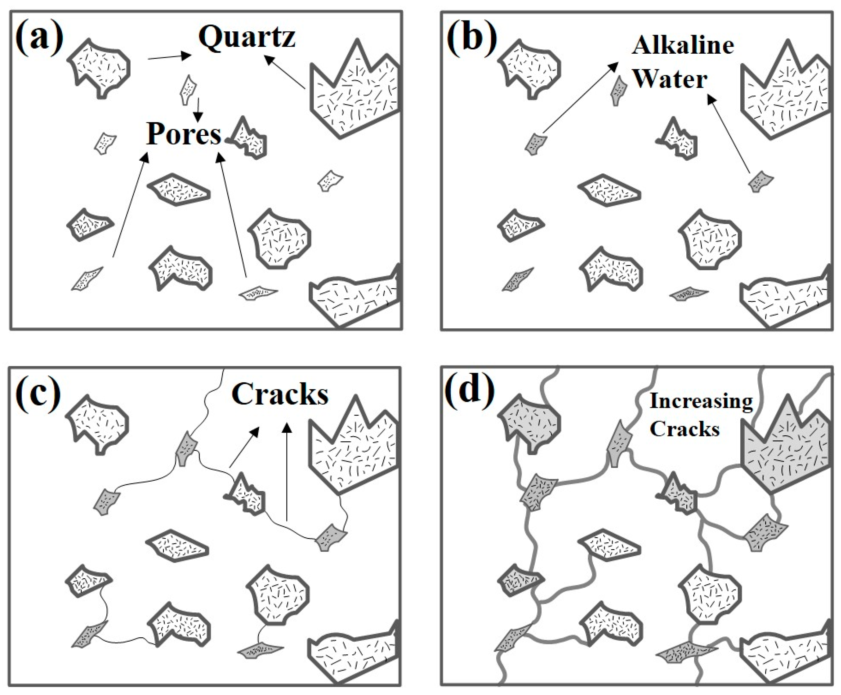
Figure 3 shows the mechanism of the process by which ASR occurs in the porcelain insulator. Stage I is the stage where internal pores are generated by deterioration during the cement curing process, a long service period, or mechanical/electrical stress. These also include the micro-pores created mainly in the initial stage of the manufacturing process and then enlarged by water permeation. In Stage II, alkali-silica gel is formed by reaction with water. The SiO
2 component within the cement reacts with high pH Na
+ and K
+ ions and generates Na
2SiO
3·2H
2O. Stage III is a process in which alkali-silica gel erodes silica and alkali components in the cement causing the expansion of the cracks. Solid state SiO
2 and aqueoussolutions of Na
+ and OH
− form NaHSiO
3. Then, volume expansion occurs. Finally, Stage IV is crack propagation or growth due to water permeation.
The high stresses inside the cement expand the volume of the cement and lead to cracks. In general, it has been reported that amorphous silica is highly susceptible to ASR. The silica that reacts in these four steps is mostly amorphous, which is the cause of accelerated deterioration. The subsequent deterioration of the cement inside the porcelain insulator has the greatest influence on the mechanical characteristics and it may cause the insulation resistance of the porcelain insulator to deteriorate [
20].
4. Degradation Mechanism by Definition and Status Analysis of Corrosion of Iron Cap and Iron Pin
In
Table 1, pollution grades A, B, and C were granted for the porcelain insulators that began service in 1979. In Korea, the grades of pollution are defined according to the distance from the coast. For the case of grade A, it means that the pollution rate is very low.
In the case of a coastal region, the level of pollution depends on the distance of insulators from sea. According to the guideline in the case of the eastern coast, a site 3.5 to 5.7 km from the sea has the least polluted insulators graded as “A”. However, when distance from the sea is between 2.0 to 3.3 km, the insulators are categorized as grade “B” polluted. When the distance lowers to 1.2 to 2.0 km the insulators can be categorized as grade “C”. Sites with a distance lower than 1.2 km have the most polluted insulators, grade “D”. Considering the west coast, it can be observed that a site 9.5 to 20.2 km from the sea has the least polluted insulators, grade “A”. Whereas sites which are 4.8 to 9.5 and 2.4 to 4.8 km from the sea have been categorized as grade “B” and “C”, respectively. However, the site closest to sea i.e., less than 2.4 km away has most polluted insulators, grade “D”. The same can be observed in case of the south coast and Jeju island. In the case of the south coast, when sites are between 2.5 to 5.0 km and 1.35 to 2.5 km from the sea, the insulators are graded as “A” and “B”, respectively. Whereas when the distance between a site and the sea is 0.7 to 1.35 km and less than 0.7 km, the pollution grade is considered to be “C” and “D”, respectively. Now considering Jeju island, if the distance of a site from the sea is between 8.0 to 16.5 km and 4.1 to 8.0 km, the insulators are graded as “A” and “B”, respectively. Moreover, when the distance between a site and the sea is 2.1 to 4.1 km and less than 2.1 km, the pollution grade is considered to be “C” and “D”, respectively.
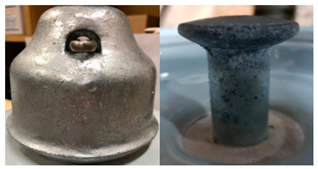
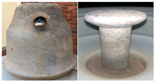
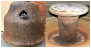
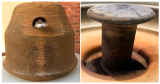
In the case of the new product (Stage I), which had never been used, no corrosion is detected by the eye. The porcelain insulator pictured in Stage II is a Pollution Level A product. Zinc plating is shown at an early stage of corrosion. The insulator does not need to be replaced immediately but must be cleaned and monitored periodically because there is some damage. The porcelain insulator pictured in Stage III is a Pollution Level B product; it has begun to degrade as corrosion progresses, and its removal from the service line should be considered. The porcelain insulator pictured in Stage IV is a Pollution Level C product; the corrosion is very severe, the metal has rust flows down to the porcelain or cement part, and the insulation resistance characteristic is poor. Rust can be seen but is not merely surface corrosion; the degradation has affected the entire structure of the insulator, which needs to be removed from the service line.
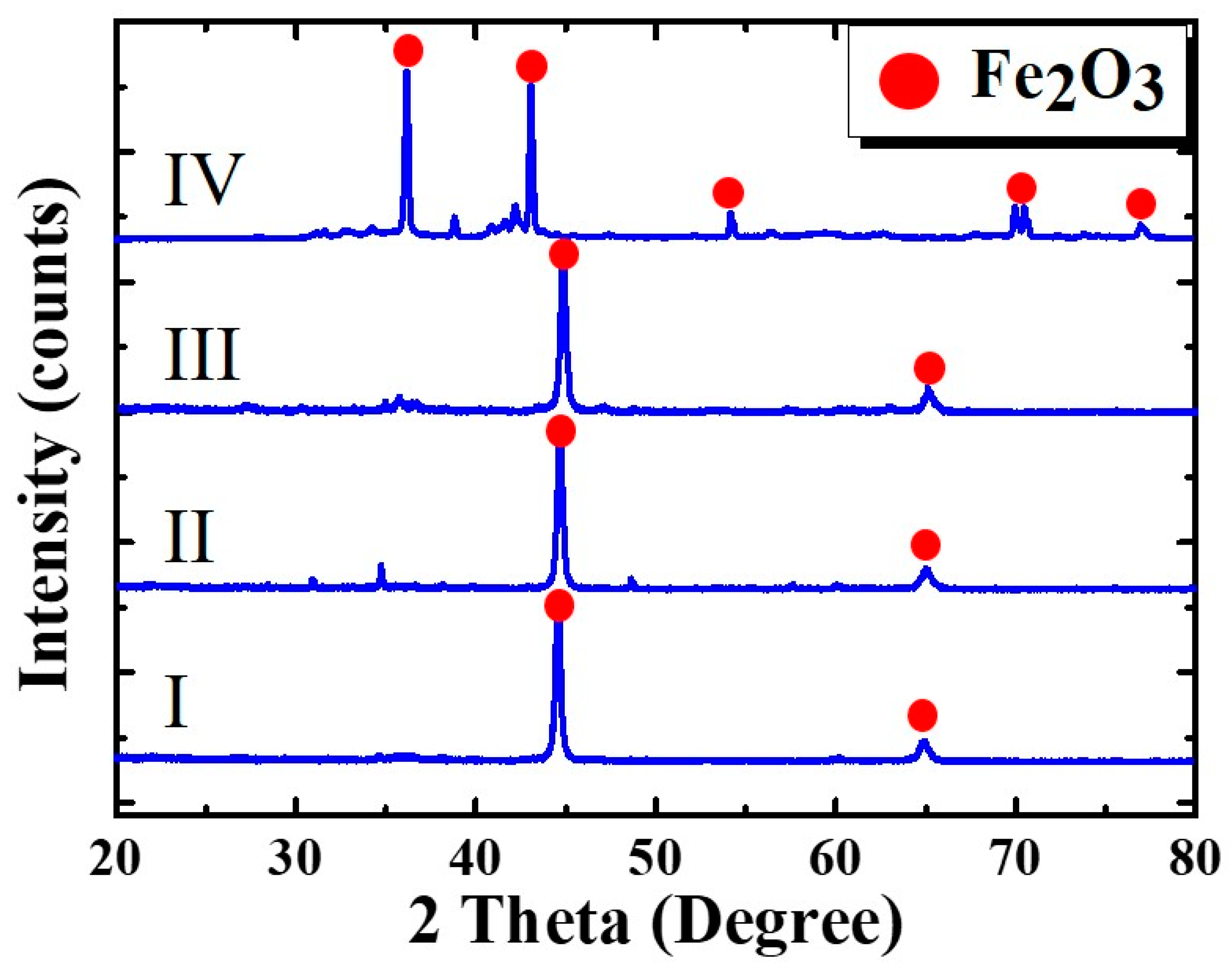
Figure 4 shows the X-ray diffraction (XRD) analysis of the iron pin. Peaks of Fe
2O
3 were observed mainly at 36, 43, 48, 54, 65, 70, and 78 degrees, and the iron pin was also found to have the same tendency, largely due to exposure to the external environment.
The more pollution, the more various peaks in the Fe2O3. In the case of a Pollution Level C, the peak was doubled compared to other cases. Even though the iron surface is zinc-coated to prevent corrosion, depending on the degree of service and the degree of contamination, corrosion occurs on the iron cap and iron pin when iron and oxygen react to form Fe2O3.
The oxidation reactions due to environmental factors in the transmission line service environment are as follows:
with the main corrosion components of the iron cap and iron pin being
The values of m, n, and p vary depending on factors including the temperature, pH value, and oxygen content. Iron oxide, a major component of the corrosion of the metal cap, was measured by X-ray diffraction. If the oxidation of the metal in the porcelain insulator is severe, the ability to support the wires between the transmission towers may be reduced, leading to accidents. Therefore, even if zinc plating is used to protect a porcelain insulator that is in service for a long period of time, once the corrosion of iron starts, rapid replacement is needed to ameliorate risk [
20].
5. Conclusions
The replacement standards for porcelain insulators are not well defined based on service period and should be defined properly to avoid accidents. In this study, the deterioration of such insulators was analyzed by service period and pollution degree, with a focus on the use of 3D-CT analysis for the study of deterioration in cement. In the case of the new product that was analyzed, very small air pockets of less than 3 mm2 were found; in the case of the porcelain insulator that had been used for a long time, there were more than 20 large and small pores of 3 mm2 or more. Pore formation occurs due to erosion by gel generated by silica and alkali in the cement due to ASR and water.
This causes cracks in the cement components of the porcelain insulator, and eventually, this expands and leads to mechanical breakage of the porcelain insulator. Results indicate that the deterioration of the cement proceeds under normal atmospheric conditions over time and that mechanical properties degrade significantly.
In addition, although the cap and pin, which are mainly composed of Fe, are coated with zinc to prevent corrosion, the longer the service period of an insulator and the higher the degree of pollution, the more advanced the progress in corrosion will be. If porcelain insulator corrosion is categorized into stages based on the degree of corrosion, as in this study, each stage can contribute to establish standard replacement criteria that can inform the appropriate and timeous replacement of damaged porcelain insulators.


