Featured Application
Authors are encouraged to provide a concise description of the specific application or a potential application of the work. This section is not mandatory.
Abstract
This paper presents an air-gap magnetic field manipulation by optimized coil currents for a magnetic force enhancement in electromechanical devices. The external coil is designed near the device air-gap for manipulating the magnetic field distribution. The distribution of external coil currents is then optimized for maximizing the magnetic force in the tangential direction to the air-gap line. For the optimization, the design domain near air-gap is divided into small areas, and design variables are assigned at each small design area. The design variables determines not only the strength of coil current density (i.e., number of coil turns) but also whether the material state is coil or iron. In a benchmark actuator example, it is shown that 11.12% force enhancement is available by manipulating the air-gap magnetic field distribution using the optimized coil current. By investigating the magnetic field distribution, it is confirmed that the optimized coil current manipulated the magnetic field, forwarding a focused and inclined distribution that is an ideal distribution for maximizing the magnetic force.
1. Introduction
Electromechanical devices, such as electromagnetic actuators and electric motors, are one of the main components for automobiles, aerospace, and robotics applications. The primary design goal of the electromechanical devices might be a strong magnetic force generation in a limited device volume and mass, which means a high force density. To achieve this design goal, a magnetic field distribution is a key design factor because the strength and direction of the magnetic force are determined by the magnetic field distribution inside the devices.
The magnetic field distribution inside the electromechanical devices is mainly affected by the structural shape of the device components (i.e., soft magnetic material (i.e., iron), hard magnetic material (i.e., permanent magnet), and coil) [1]. Thus, various structural optimization studies have been performed to find the optimal shape and configurations of the device components maximizing the magnetic force. The structural shape of the soft magnetic (i.e., iron) material has been optimized to maximize the magnetic force of actuators [2,3,4,5] and electric motors [6,7,8]. The structural optimization of permanent magnet material was studied in [9,10,11,12] to determine the optimal magnet shape and magnetization directions. In [13,14,15,16,17], both iron and permanent magnet materials were simultaneously designed using structural optimization techniques. In [18,19], all three device components (i.e., iron, permanent magnet, and coil) were co-designed for maximizing the magnetic force of electromagnetic actuators. While the structural optimization techniques [2,3,4,5,6,7,8,9,10,11,12,13,14,15,16,17,18,19] are certain to be an efficient approach for enhancing the magnetic force of electromechanical devices, they have a limitation that the magnetic field distribution is indirectly handled through optimizing the shape and configuration of the device components.
As a technique to directly treat the magnetic field distribution, the magnetic field manipulation scheme was developed in [20,21,22]. In [20], the magnetic field focusing was proposed using an induced current in a periodic-ladder structure consisting of a conductivity material. Subsequently, it was shown that the focused magnetic field distribution in the air-gap enhanced the magnetic force in the normal direction of the air-gap line [21]. The force enhancement by the focused magnetic field was then experimentally validated in an actuator [22]. In these previous works [20,21,22], the magnetic field distribution in the air-gap was directly optimized using the induced current, and the force enhancement by the manipulated magnetic field was experimentally validated. However, passive manipulation using the induced current is limited in the resultant field distribution and force enhancement. Specifically, it has been observed that the force enhancement in the direction tangential to the air-gap line might not be available by the passive field manipulation based on the induced current. Thus, the manipulation by the induced current would not be useful for electric motors and actuators because they operate by the magnetic force in a tangential direction.
Meanwhile, the magnetic field manipulation using an actively controlled external current was proposed in [23,24,25,26]. In [23], a switch-mounted loop array was proposed for the active control of the magnetic field, and its analytical model was presented. In [24], the design of a programmable coil array was presented for the manipulation of the electromagnetic field. In [25], a current-controlled coil array was proposed for the magnetic field focusing. In [26], the active control of the magnetic field was implemented using multiple electromagnets. In these previous works [23,24,25,26], the active manipulation of the magnetic field distribution using the external current was theoretically studied and experimentally validated for wireless power transfer, magnetic field communication, and biomedical imaging applications. However, none of these previous works have addressed the active magnetic field manipulation for enhancing the magnetic force in electromechanical devices.
Accordingly, this work aims to present the magnetic field manipulation using external coil currents for enhancing the magnetic force in a tangential direction to the air-gap line. An ideally manipulated air-gap magnetic field distribution for maximizing the tangential direction force is first investigated. The ideally manipulated magnetic field distribution might not be realized using the external coil current, but it might be available to find the best possible distribution of coil current. In order to find this best possible distribution, a gradient-based numerical optimization scheme is proposed in this work. As an optimization strategy, the concept of topology optimization [27] is appropriately modified and applied. More specifically, the design domain near the air-gap is divided into small design areas, and design variables are assigned at every small design area. Here, the design variables control not only the strength of the current density (i.e., number of coil turns) but also the magnetic permeability. The current density and permeability are related to the magnetic field distribution, determining the magnetic force. In the optimization, the total sum of external coil currents is constrained in terms of the magnetic field manipulation. By solving the optimization problem, the best possible coil current distribution that maximizes the tangential direction magnetic force by the manipulated magnetic field could be determined.
The paper is organized as follows. Section 2 explains the ideal magnetic field distribution for maximizing the tangential direction magnetic force. In Section 3, the optimization strategy to find the optimal coil currents is explained. The optimization problem formulation is then provided in Section 4. In Section 5, the optimization result is provided, and the effectiveness of the magnetic field manipulation using an optimized coil current is validated. Conclusions are provided in Section 6.
2. Ideal Magnetic Field Distribution for Magnetic Force Enhancement
Before performing the optimization of coil currents, ideal air-gap magnetic field distribution for maximizing the tangential-direction magnetic force is explained in this section. An ideally manipulated magnetic field distribution between two soft ferromagnetic (i.e., iron) parts could maximize a tangential direction magnetic force exerted on the iron part. Figure 1a shows the magnetic field lines in a common operating situation, and Figure 1b shows ideally manipulated magnetic field lines for maximizing the magnetic force in a tangential direction to the air-gap line.
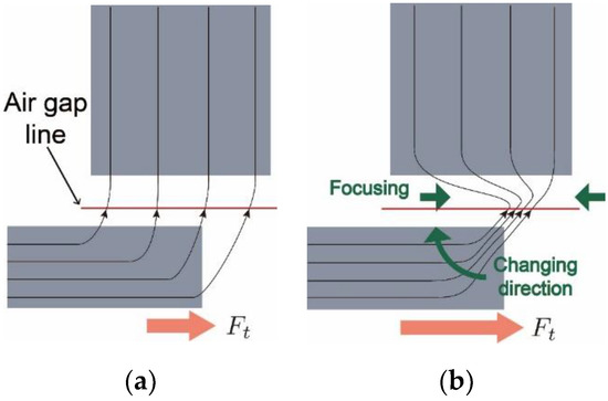
Figure 1.
Magnetic field lines (a) in a common operating situation, (b) manipulated ideally for maximizing tangential direction magnetic force.
The ideal magnetic field distribution for maximizing tangential direction magnetic force could be explained theoretically using Maxwell’s stress tensor formulation [28]. Maxwell’s stress tensor formulation describes the relation between magnetic force and magnetic field distribution along an integration path (i.e., air-gap lines):
where S is any closed surface surrounding the object, μ0 is the air permeability, n and t are normal and tangential unit vectors to the integration path, and Bn and Bt are magnetic flux densities, respectively, in normal and tangential directions with respect to the integration path. In (1), the second term of the right-hand side corresponds to the tangential direction magnetic force Ft.
By investigating (1), ideal magnetic field distributions, for maximizing the tangential direction magnetic force Ft, could be found out. The tangential direction force Ft is calculated as the integral of the multiplication of normal and tangential magnetic flux density Bn and Bt. If the amount of the magnetic flux along with the air-gap integration path, , stayed constant, the tangential force Ft might be maximized when the focused normal direction flux density, Bn, is the same with the focused tangential direction flux density, Bt. In other words, the magnetic field that is focused on a direction inclined 45 degrees to the integration path might be ideal for maximizing the tangential force, Ft, as described in Figure 1b.
The conceptual comparison of an evenly and focused distribution with 45 degrees inclination is presented in Figure 2. The tangential direction magnetic force, Ft, is zero when the air-gap magnetic field is evenly distributed in the normal direction, as shown in Figure 2a. The magnetic force, Ft, for focused and 45-degree inclined field in Figure 2c, is five times higher than that for evenly distributed and 45-degree inclined field in Figure 2b. In all three cases, the magnetic flux Φ is identical. This comparison showed how the focused and 45-degree inclined magnetic field could be considered as an ideal distribution.
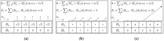
Figure 2.
Conceptual comparison of (a) evenly distributed normal-direction magnetic field, (b) evenly distributed and 45 degrees inclined magnetic field, (c) focused and inclined magnetic field.
3. Optimization Strategy
This section explains the optimization strategy for finding the optimal coil currents for maximizing the magnetic force. Figure 3 shows the two-dimensional finite element model of a benchmark actuator used in this work. The magnetostatic analysis is performed using Maxwell’s equation with vector potential A formulation.
where B is magnetic flux density, is relative permeability, and J is a current density. In the two-dimensional analysis, only z-directional vector potential Az is a state variable. The yoke and plunger are made of silicon steel with a relative permeability of 1200, and the coil winding is located around the yoke pole. A current in the winding is also set to 10 A with 100 number of turns. The Dirichlet boundary condition is applied at the outer boundary of the model. For the optimization, directional (i.e., tangential direction to the air-gap line) magnetic force at 21 equally spaced plunger locations (m = 0, …, 20) is calculated.
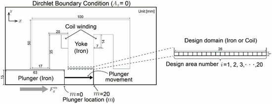
Figure 3.
Finite element model of a benchmark actuator with boundary condition and design domain.
In the benchmark model in Figure 3, the design domain is located at the tip of the yoke near the air-gap. As with topology optimization [27], the design domain is divided into small areas, and the design variable is assigned at th design area. Here, the physical meaning of the design variable is set as the number of coil turns at th design area, and the sign of represented the direction of coil currents. If the number of coil turns is zero (i.e., ), the th design area represented the iron material instead of a coil. It means that the design variable determined whether the th design area is iron or coil material. For this, not only the coil current density but also relative magnetic permeability of th design area are determined by the design variable . In order to apply the gradient-based optimization algorithm, and are interpolated using the following functions:
where is the coil current, is the volume of th design area, and are, respectively, the relative permeability of coil and iron material, and is the parameter for the relaxed interpolation function. Figure 4a,b, respectively, show the plot of the proposed interpolation functions (3) and (4) with respect to the design variable . The coil current density in (3) is simply proportional to the design variable . The relative permeability in (4) became the iron permeability when the design variable is zero (i.e., zero coil turns), while it became the coil permeability when the design variable is not zero. The exponential function in (4) is introduced to relax a discontinuous function for discrete material states (i.e., iron or coil) into the continuous function. Here, the continuous function is required to apply a gradient-based optimization algorithm; refer to interpolation functions in topology optimization to control material states in [2,3,4,5,6,7,8,9,10,11,12,13,14,15,16,17,18,19]. The proposed interpolation functions in (3) and (4) could determine the number of coil turns together with the material state.
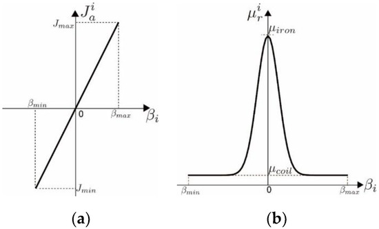
Figure 4.
The plot of the interpolation functions for (a) current density in (3), and (b) relative permeability in (4), with respect to design variable .
In the optimization result, the number of coil turns need to be an integer value. To achieve this, the continuous and discrete optimization scheme proposed in [17], ref. [29] is employed in this work. In this scheme, a physical property is penalized when a corresponding design variable is located at intermediate values between the desired integer values. The optimization in this work aimed to maximize the magnetic force. The magnetic force becomes large when the magnetic flux density B is large. The magnetic flux density B is large when the electric current input is large. Therefore, reduced current magnitude worked as penalization in this optimization problem for maximizing the magnetic force. Using this working principle, the physical property in (3) is penalized (i.e., reduced) when the design variable is not located at an integer value. For this, the current is first defined as
where is the fixed maximum current, and is the penalty parameter. Figure 5 shows the plot of the current with respect to the design variable . When the penalty parameter is set to 1, the current is not penalized, which means is fixed as at every value of . As the parameter decreased, the strong penalty is applied to when the design variable is not located at integer values. Consequently, the design variable tended to locate at integer values to avoid the penalization on the current . It is noted that the parameters in (4) and in (5) are updated using the continuation scheme proposed in [17], ref. [27] during the optimization iteration.
Figure 5.
The plot of the current in (5) with respect to the design variable
When the design variable is located around zero, the aforementioned penalization scheme did not work because the penalization in did not pass to the current density in (3) due to the small value of . To resolve this problem, the electric current in (3) is defined as
Here, the current is set as zero when the design variable is located near zero. If the design variable is located near zero, it tended to move to zero (i.e., desired discrete integer number) through the penalization of the permeability in (4) instead of the penalization in (5). Thus, the range ±0.7 in (6) is related to the function shape of (4). A smaller range (e.g., ±0.5) might be suitable when the function shape in Figure 4b is narrow (i.e., large p in (4)), and vice versa. When the design variable is located far away from zero, the penalization scheme in (5) is applied to achieve the design result with discrete integer numbers. The proposed continuous and discrete optimization scheme in (5) and (6) enabled us to achieve a discrete integer number of coil turns with continuous design variables.
4. Optimization Problem Formulation
The design goal of this work is set to find the optimal coil current distribution maximizing the average force acting on the plunger during its movement, as shown in Figure 3. To achieve the design goal, the optimization problem is formulated as
In the benchmark actuator model in Figure 3, the objective function (8) is calculated as the average of the directional (i.e., tangential direction to the air-gap line) magnetic force at 21 equally spaced plunger locations:
Here, the magnetic force is calculated using Maxwell’s stress tensor formulation in (1). In (9), the element stiffness matrix and force vector are derived using the finite element formulation of Maxwell’s equation in (2). The design variable control the distributions of current density and relative permeability through (3) and (4), which are related to the magnetic flux density B through (2). The magnetic flux density B is then connected with the objective function Favg through (1) and (12). The constraint in (10) is applied to confining the total number of coil turns below the target value . The constraint in (11) is for setting the maximum value of a number of coil turns as .
In this work, the objective function (8) and the system of linear Equation (9) are computed using the finite element commercial software, COMSOL V5.3. The optimization problem (7)–(11) is solved using the globally convergent method of moving asymptotes (GCMMA) algorithm. The GCMMA code in MATLAB R2013b is combined with COMSOL for the implementation.
5. Optimization Result
The proposed optimization strategy and problem formulation are applied for finding the optimal coil current distribution in the benchmark actuator model in Figure 3. Specifically, the number of coil turns (i.e., design variable ) at the design domain located at the yoke near the air-gap is determined for maximizing the average force during the plunger movement in a tangential direction to the air-gap line. In this work, the number of design variable is set to 20, which means the design domain is divided into 20 small areas. The total number of coil turns, in (10), is set to 20, which is empirically determined as a value that could reveal the magnetic field manipulation effect. When is too large or small compared to winding turns, the manipulation effect is reduced. The maximum number of coil turns in (11) is also set to 20, and the coil current coil in (5) is set to 10 A.
Figure 6a–d shows the distribution of design variables during the optimization iteration. As shown in Figure 6a, the design variables are evenly distributed as 0.1 at the initial iteration. As the optimization iteration proceeded, the design variables moved to find the optimal distribution in Figure 6b,c. Then, the design variables tended to converge into discrete integer numbers, as shown in Figure 6d, due to the proposed continuous and discrete optimization scheme in (5) and (6).
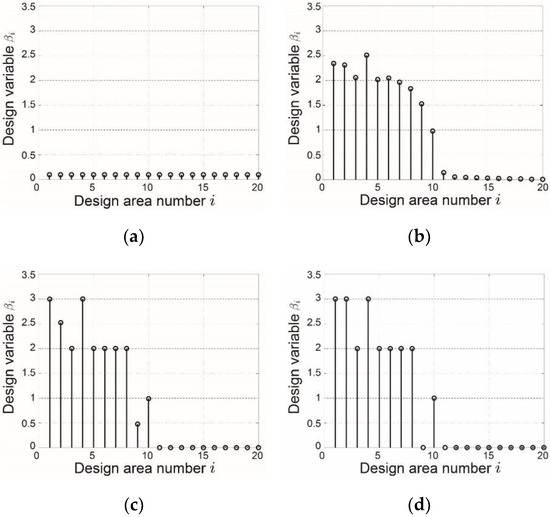
Figure 6.
Distribution of the design variables during the optimization iteration: (a) iteration step 1, (b) iteration step 51, (c) iteration step 102, and (d) iteration step 192 (final step).
The final optimization results are described in Figure 7. Figure 7a,b shows the distribution of current density magnitude () and relative permeability at 20 small design areas, respectively. In Figure 7b, the area where the relative permeability is 1200 represents the iron material, and the area where is 1 represents the coil. Using the proposed formulation, both the current density and material state at the design domain are successfully determined simultaneously. In the optimization result, it is observed that the left part of the design domain is optimized to have a strong current density, while the right part is designed as iron material.
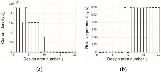
Figure 7.
Final optimization result—distribution of (a) magnitude of current density , (b) relative permeability at the design domain.
To validate the effectiveness of the design result, the force profile of the design with magnetic field manipulation by optimized current distribution is compared with that of an original design without manipulation (i.e., no coil currents near the air-gap) in Figure 8. Here, the original design is built by setting all design variables as zero, which means that every design domain is simply set as the iron material. In the original design, the number of winding turns is set as 120, which is 20 (i.e., the total number of coil turns in design domain) higher than the optimized coil current case, for a fair comparison. As shown in Figure 8, the design with optimized coil current successfully enhances the average magnetic force compared to the original design. The average force Favg (i.e., objective function in (8)) of the design with optimized coil current is calculated as 128 N, which is 11.12% higher than that of the original design. This force enhancement might come from the magnetic field manipulation by the optimized current distribution.
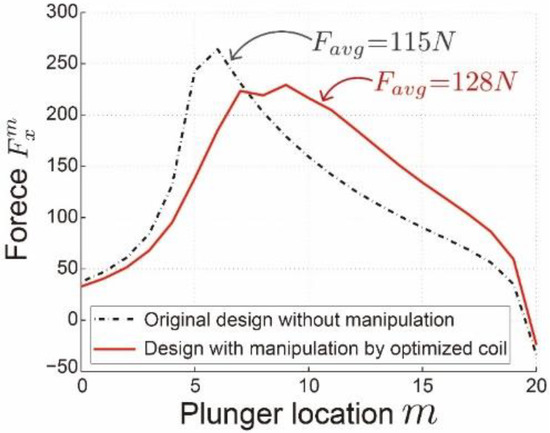
Figure 8.
Force profile comparison between original design without manipulation and design with manipulation by optimized coil current.
In order to confirm that the force enhancement results from the manipulated magnetic field, the magnetic flux density along the air-gap line is investigated. Figure 9a,b compares the magnetic flux density distribution along the air-gap line of the original design without magnetic field manipulation and the design with the manipulation by optimized coil currents. As expected, it is observed that the optimized coil currents manipulated the air-gap magnetic field toward the ideal field distribution. In the original design, the magnetic field in the left part of the air-gap line mainly flew in an upward direction, and its magnitude was uniform. On the other hand, the magnetic field of the optimal design was manipulated into the right-upward direction, and its magnitude became focused-shape. It was noted again that the focused and inclined magnetic field was the ideal field distribution that could lead to the magnetic force enhancement in the tangential direction, as discussed in Section 2.
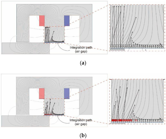
Figure 9.
Magnetic flux density (black-colored arrow) on air-gap at 9th plunge location (): (a) original design without magnetic field manipulation, (b) design with the field manipulation by optimized coil current. The red color in the design domain represents the strength of the current density.
6. Conclusions
This work aimed to propose a magnetic field manipulation using optimized coil current to enhance the tangential direction magnetic force. An ideal field distribution for maximizing the tangential direction force was first provided by investigating Maxwell’s stress tensor formulation. Subsequently, the optimization for determining the coil current near air-gap was performed. For the optimization, the design domain near air-gap was divided into small areas, and the design variables were assigned at each small area. The design variables determined not only the number of coil turns but also whether the material state was coil or iron. For this, the appropriate material property interpolation functions were proposed in this work. The optimization problem was then formulated to determine the design variables maximizing the averaged magnetic force. By solving the optimization problem using the mathematical programming method, the optimal coil current distribution was successfully obtained. The average force of the design with the magnetic field manipulated by optimized coil current was expected to 11.12% higher than that of the original design without magnetic field manipulation. The future work would include the experimental validation of the magnetic field manipulation using the optimized coil currents for force enhancement. The construction of two current sources for winding and coils near the air-gap is a challenging but interesting topic.
Author Contributions
J.L. (Jaejoon Lee) conceptualization, methodology, software, and writing—original draft preparation; J.L. (Jaewook Lee) methodology, formal analysis, and writing—review and editing. All authors have read and agreed to the published version of the manuscript.
Funding
This research was supported by a grant (17TLRP-C135446-01, Development of Hybrid Electric Vehicle Conversion Kit for Diesel Delivery Trucks and its Commercialization for Parcel Services) from Transportation and Logistics Research Program (TLRP) funded by Ministry of Land, Infrastructure, and Transport of the Korean government.
Conflicts of Interest
The authors declare no conflict of interest.
References
- Dede, E.M.; Lee, J.; Nomura, T. Multiphysics Simulation: Electromechanical System Applications and Optimization; Springer: Berlin, Germany, 2014. [Google Scholar]
- Yoo, J.; Kikuchi, N. Topology optimization in magnetic fields using the homogenization method. Int. J. Numer. Methods Eng. 2000, 48, 1463–1479. [Google Scholar] [CrossRef]
- Park, S.; Min, S. Design of magnetic actuator with nonlinear ferromagnetic materials using level-set based topology optimization. IEEE Trans. Magn. 2010, 46, 618–621. [Google Scholar] [CrossRef]
- Lee, J.; Kikuchi, N. Structural topology optimization of electrical machinery to maximize stiffness with body force distribution. IEEE Trans. Magn. 2010, 46, 3790–3794. [Google Scholar] [CrossRef]
- Lee, S.-W.; Lee, J.; Cho, S. Isogeometric shape optimization of ferromagnetic materials in magnetic actuators. IEEE Trans. Magn. 2016, 52, 7200208. [Google Scholar] [CrossRef]
- Lee, J.; Seo, J.H.; Kikuchi, N. Topology optimization of switched reluctance motors for the desired torque profile. Struct. Multidiscip. Optim. 2010, 42, 783–796. [Google Scholar] [CrossRef]
- Choi, J.-S.; Izui, K.; Nishiwaki, S.; Kawamoto, A.; Nomura, T. Topology optimization of the stator for minimizing cogging torque of IPM motors. IEEE Trans. Magn. 2011, 47, 3024–3027. [Google Scholar] [CrossRef]
- Watanabe, K.; Suga, T.; Kitabatake, S. Topology optimization based on the on/off method for synchronous motor. IEEE Trans. Magn. 2018, 54, 1–4. [Google Scholar] [CrossRef]
- Choi, J.-S.; Yoo, J. Design of a Halbach magnet array based on optimization techniques. IEEE Trans. Magn. 2008, 44, 2361–2366. [Google Scholar] [CrossRef]
- Insinga, A.R.; Bjørk, R.; Smith, A.; Bahl, C.R.H. Globally optimal segmentation of permanent-magnet systems. Phys. Rev. Appl. 2016, 5, 064014. [Google Scholar] [CrossRef]
- Insinga, A.R.; Bjørk, R.; Smith, A. Optimally segmented permanent magnet structures. IEEE Trans. Magn. 2016, 52, 7210306. [Google Scholar] [CrossRef]
- Lee, J.; Nomura, T.; Dede, E.M. Topology optimization of Halbach magnet arrays using isoparametric projection. J. Magn. Magn. Mater. 2017, 432, 140–153. [Google Scholar] [CrossRef]
- Bjørk, R.; Bahl, C.R.H.; Insinga, A.R. Topology optimized permanent magnet systems. J. Magn. Magn. Mater. 2017, 437, 78–85. [Google Scholar] [CrossRef]
- Ishikawa, T.; Mizuno, S.; Krita, N. Topology optimization method for asymmetrical rotor using cluster and cleaning procedure. IEEE Trans. Magn. 2017, 53, 7001504. [Google Scholar] [CrossRef]
- Asai, Y.; Ota, T.; Yamamoto, T.; Hirata, K. Proposed of novel linear oscillating actuator’s structure using topology optimization. IEEE Trans. Magn. 2017, 53, 8203204. [Google Scholar] [CrossRef]
- Teyber, R.; Trevizoli, P.V.; Christiaanse, T.V.; Govindappa, P.; Niknia, I.; Rowe, A. Permanent magnet design for magnetic heat pumps using total cost minimization. J. Magn. Magn. Mater. 2017, 442, 87–96. [Google Scholar] [CrossRef]
- Lee, J.; Yoon, M.; Nomura, T.; Dede, E.M. Topology optimization for design of segmented permanent magnet arrays with ferromagnetic materials. J. Magn. Magn. Mater. 2018, 449, 571–581. [Google Scholar] [CrossRef]
- Lee, J.; Dede, E.M.; Nomura, T. Simultaneous design optimization of permanent magnet, coils, and ferromagnetic material in actuators. IEEE Trans. Magn. 2011, 47, 4712–4716. [Google Scholar] [CrossRef]
- Lee, J.; Lee, S.-W.; Kim, K.; Lee, J. Multi-material topology optimization of magnetic actuator with segmented permanent magnets. IEEE Trans. Magn. 2018, 54, 8202706. [Google Scholar] [CrossRef]
- Banerjee, D.; Lee, J.; Dede, E.M.; Iizuka, H. Kilohertz magnetic field focusing in a pair of metallic periodic-ladder structures. Appl. Phys. Lett. 2011, 899, 093501. [Google Scholar] [CrossRef]
- Dede, E.M.; Lee, J.; Guo, Y.; Zhou, L.Q.; Zhang, M.; Banerjee, D. Kilohertz magnetic field focusing and force enhancement using a metallic loop array. Appl. Phys. Lett. 2012, 101, 023506. [Google Scholar] [CrossRef]
- Lee, J.; Dede, E.M.; Banerjee, D.; Iizuka, H. Magnetic force enhancement in a linear actuator by air-gap magnetic field distribution optimization and design. Finite Elem. Anal. Des. 2012, 58, 44–52. [Google Scholar] [CrossRef]
- Tanaka, H.; Iizuka, H. Active control of magnetic field by manipulating induced currents in two-dimensional switch-mounted loop array. IEEE Trans. Magn. 2013, 49, 5682–5686. [Google Scholar] [CrossRef]
- Gao, F.; Zhang, F.; Wakatsuchi, H.; Sievenpiper, D.F. Synthesis and design of programmable subwavelength coil array for near-field manipulation. IEEE Trans. Microw. Theory Tech. 2015, 63, 2971–2982. [Google Scholar] [CrossRef]
- Choi, B.; Kim, J.; Cheon, J.; Rim, C. Synthesized magnetic field focusing using a current-controlled coil array. IEEE Magn. Lett. 2016, 7, 6501504. [Google Scholar] [CrossRef]
- Jeon, J.; Son, H. Active control of magnetic field using eDMP model for biomedical applications. IEEE Trans. Mechatron. 2018, 23, 29–37. [Google Scholar] [CrossRef]
- Bendsøe, M.P.; Kikuchi, N. Generating optimal topologies in structural design using a homogenization method. Comput. Methods Appl. Mech. Eng. 1988, 71, 197–224. [Google Scholar] [CrossRef]
- Ito, M.; Tajima, F.; Kanazawa, H. Evaluation of force calculating methods. IEEE Trans. Magn. 1990, 26, 1035–1038. [Google Scholar] [CrossRef]
- Lee, J.; Kim, D.; Nomura, T.; Dede, E.M.; Yoo, J. Topology optimization for continuous and discrete orientation design of functionally graded fiber-reinforced composite structures. Compos. Struct. 2018, 201, 217–233. [Google Scholar] [CrossRef]
© 2019 by the authors. Licensee MDPI, Basel, Switzerland. This article is an open access article distributed under the terms and conditions of the Creative Commons Attribution (CC BY) license (http://creativecommons.org/licenses/by/4.0/).