Article

System to Evaluate Movement of Biological Contaminants in Soil

1
Department of Agricultural and Biological Engineering, University of Illinois Urbana-Champaign, 1304 W. Pennsylvania Ave., Urbana, IL 61801, USA
2
Department of Biology, University of South Florida St. Petersburg, 140 7th Ave S, St. Petersburg, FL 33701, USA
3
Department of Pathobiology, University of Illinois at Urbana-Champaign, 2001 S Lincoln Ave. Urbana, IL 61801, USA
*
Author to whom correspondence should be addressed.
Environments 2019, 6(3), 33; https://doi.org/10.3390/environments6030033
Submission received: 2 February 2019 / Revised: 27 February 2019 / Accepted: 4 March 2019 / Published: 8 March 2019

Abstract

:
Soil columns have been utilized in hydrology to study vertical solute transfer through porous material for decades. Soil columns are typically designed as open tubes with soil held in place with meshing. While this open design is sufficient for non-hazardous particles, it is not ideal for hazardous biological contaminants that may be harmful to humans. The design of this study features a closed soil column system for use with potentially hazardous biological components. The apparatus is comprised of a mist nozzle, flow-reducing cap, and meshing to simulate rainfall on each soil column. After percolating through the soil, water and contaminants pass through a funnel coupling and discharge tube into a collection container. For additional safety, the soil column design fits within a standard biosafety cabinet for use with hazardous contaminants. Its modular design allows for simple maintenance, water flowrate adjustment, and versatility that encourages use in multiple applications. These soil columns were created to study the vertical flow of pathogens, pesticides, and other biological agents. Further experimentation with various hazardous components will develop a better understanding of their fate and transport in soil. This paper details the construction processes and testing methods to validate the system’s ability to replicate a desired flowrate, which is a precursor to studying the vertical transport of pathogens and other agents through soil.

1. Introduction

Soil columns are used for studying particle transport through a soil medium while controlling environmental parameters. The objective of this study is to design and construct a versatile soil column system for use with multiple applications, including potentially harmful biological agents. For the purposes of this study, a soil column is defined as a vertical cylinder of soil and shell prepared for the experimentally-controlled study of particle and fluid movement in a saturated or unsaturated soil medium. A lysimeter is defined as an instrument used to measure net additions to the soil from precipitation or irrigation [1]. As stated by Lewis and Sjöstrom (2010) [2], studies of particle and fluid movement can range widely, from transport model evaluation to evapotranspiration studies to fate and transport of various agents such as pesticides, microbes, heavy metals, and antibiotics. Vertical soil column systems can be very simply described as having a soil column shell and collection container. The soil column shell is filled with soil and suspended above a collection container. As the solution passes through the column, researchers study the interaction between soil and the solution. If an agent of interest was added to the soil or solution, the solution collected in the collection container can be analyzed to determine how much of the agent of interest was able to pass completely through the column.

1.1. Review of Soil Column Design

In their review of optimizing the experimental design of soil columns, Lewis and Sjöstrom (2010) [2] stated that “there is no single [soil column] experimental setup which will be suitable for all applications.” When discussing lysimeters, Howell (2005) [1] concedes the same idea; there is no one standard for lysimeter construction or design. However, there is a universal guiding principle that the lysimeter and soil column conditions must be representative of the conditions that wish to be studied. These statements are proven by the multitude of soil column designs that are utilized for their equally as significant number of purposes. An objective of this study is to design a modular soil column system that is versatile enough to accommodate as many applications as possible, including those that involve agents that are potentially harmful to humans.
Soil columns have been constructed from materials such as stainless steel, acrylic, polyvinyl chloride (PVC), and glass. The most common among these being acrylic, glass, and stainless steel [2]. The experimental conditions most often dictate which material is chosen. Transparent materials, such as glass or acrylic, are necessary for experiments that require the interior to be visible. Transparent soil columns have been used to illustrate water flow and demonstrate solute transport with dye [3]. Schlossberg and Karnok (2002) [4] detail the construction of an acrylic soil column apparatus for the purpose of water flow education. Stainless steel is a preferable material choice if the soil column must have decent strength, will be located outside in the elements for long periods of time, or is simply too large for realistic use of other materials [2]. Ngo et al. (2014) [5] used stainless-steel soil columns to study the transport behavior of polycyclic aromatic hydrocarbon contaminants through soil and groundwater. The relative inactivity of stainless steel with organic compounds made it more suitable for this application. No dedicated stainless-steel soil column construction procedures were found. Plastics such as PVC are “easily and economically used in most bench scale applications” but are impractical for large applications due to their relative flexibility [2]. Gruber et al. (2005) [6] chose PVC soil columns to study the effectiveness of filtration of manure-born coliforms by soil. Brief descriptions of the construction of PVC soil columns are readily available [7,8,9]; however, no dedicated PVC soil column construction procedures were found. Refer to Lewis and Sjöstrom (2010) [2] for more details on what materials are suitable for a range of research purposes.
High rigidity is a required characteristic for conventional soil columns. It is determined by both column material and wall thickness. Soil columns made of materials such as stainless steel can maintain an acceptable rigidity with a thinner column wall. However, plastic-based materials such as polytetrafluoroethylene (PTFE), polyethylene (PE), acrylics, and polycarbonates require a thicker soil column wall to compensate for their relatively higher flexibility. These plastics are not recommended for applications requiring an outer diameter of 1 m or larger due to rigidity constraints. For soil columns over 1 m3, Lewis and Sjöstrom (2010) [2] suggest consulting with a structural engineer. The size of the soil column, or more specifically its interior surface area, has been shown to affect the risk of sidewall preferential flow. Corwin (2000) [10] defines sidewall flow as “an artificial channeling of water due to the separation of the soil from the lysimeter wall creating an airspace.” Preferential flow can be caused by improper soil packing, column flexing disturbing the soil, or increased permeability of soil in contact with the sidewall [11]. Bergström (2000) [12] recommends a surface cross-sectional area of at least 0.05 m2, corresponding to a soil column of 0.25 m diameter, to combat preferential sidewall flow. Lewis and Sjöstrom (2010) [2] expand and simplify this by recommending soil columns with a diameter to length ratio of 1:4. Feyereisen (2009) [13] used spacers to create a gap between the soil and sidewall. They then removed the spacers and sealed the gap with petroleum jelly to prevent sidewall preferential flow caused by the expansion and contraction of soil during wet and dry cycles.
In this study, a soil column has been defined as being cylindrical in shape and vertically-oriented. However, minute alterations to the cylindrical shape have been shown to improve functionality. For example, the addition of annular rings minimizes sidewall preferential flow by redirecting flow inward and away from the sidewall [10]. Chrysikopoulos and Syngouna [14] studied the effect of gravity and soil column orientation on colloid transport. They found that particle attachment and deposition is generally greater for up-flow than down-flow. The effects of flow direction on fate and transport are relatively unexplored and could have a significant impact on future soil column experiments. The design presented in this study is limited to and focuses on downward flow.
The accessibility of a soil column design’s components is important when considering its application viability. For most bench-top applications of soil columns, materials are readily accessible. As soil columns increase in size, their parts, or more specifically the material the parts are made of, become more difficult to acquire. This study focuses only on soil columns that are compact enough to reside on a bench top and within a standard biosafety cabinet.
Additional instrumentation accessories are necessary for data analysis that is relevant to the experimental design. The soil column design in this study has been constructed for testing of a saturated soil regime without the use of any instrumentation. Common instrumentation in saturated soil columns include sampling ports, probes, or gages.

1.2. Review of Soil Column Research

Pathogens and microbes have been the subject of soil column research. Pathogens are estimated to account for a total of 16% of overall total global potential loss among crops [15]. This demonstrates a need for research in pathogen-crop interactions. Soil inevitably plays a role as a medium of transfer between pathogen-rich agricultural waste and crops. This role makes pathogen-soil interaction a valuable pursuit in research. Schijven and Hassanizadeh (2000) [16] evaluated sticking efficiencies between pathogen and soil particles and its relation to pH and surface charge. Virus removal by passage through soil appeared to decrease as distance travelled increased, with the upper 17-cm of a soil column boasting a significantly higher rate of virus removal than its lower depths. Bacteria such as Escherichia coli are frequently responsible for foodborne outbreaks. According to the Centers for Disease Control and Prevention (CDC), E. coli was responsible for approximately 290 reported cases of illness and one death in 2018. This and the many other negative effects of bacteria make them a suitable candidate for soil column research. For example, Gruber et al. (2005) [6] determined that lower flow velocity through soil columns increased E. coli attachment to soil and E. coli attachment decreased with increased manure content. Therefore, soil columns are suitable for studying both microbe-soil and pathogen-soil interactions.
Heavy metals are a potential environmental threat when accumulated in soil. Camobreco et al. (1996) [16] tested effluent from both disturbed and undisturbed soil columns input with dilute solutions containing Cd, Zn, Cu, and Pb. Knowledge of the mobility of these heavy metals have been determined primarily based on soil column studies [17]. They found that preferential paths in the undisturbed soil columns may increase heavy metal mobility through a soil profile and that previous leaching studies may have greatly underestimated heavy metal mobility in the field.
Antibiotics, such as sulfadiazine, are administered to agricultural livestock and are at risk of entering the soil through manure. It can enter the soil either directly from the livestock’s manure or indirectly by application of manure to the soil. Wehrhan et al. (2006) [18] used soil columns to test modelling approaches to identify transport and sorption mechanisms of sulfadiazine. Rabølle and Spliid (2000) [19] analyzed sorption and mobility of four different antibiotic compounds in various types of soils. The use of soil columns allowed them to begin the process of a risk assessment of antibiotics in the soil environment.

1.3. Gaps in Literature

Despite the long history of soil column research, there are few resources that detail soil column construction and design. This gap in literature is mostly due to the versatility of soil columns and their ability to change drastically in design to suit their purposes. The wide design possibilities make it impossible to create a soil column system that is suitable for all applications. However, a goal of this study is to design and construct a soil column system that is compatible with a wide range of design considerations.
Soil column experiments in the literature are presented with the assumption that the reader already understands the process of constructing the soil column. There is a need for an introduction to soil column design for those that wish to create their own, but do not already know the process and design considerations. This hypothetical introductory material could potentially bridge the gap between previously published soil column research and researchers that are just beginning in soil column research.
Design and construction may change depending on soil column material. Schlossberg and Karnok (2002) [4] discussed the construction methods of an acrylic soil column. Detailed construction methods with other common materials such as stainless steel, glass, and PVC appear to be missing from current literature. Design recommendations for each material, similar to those of Lewis and Sjöstrom (2010) [2], would be helpful with additional guidance on construction procedure.
Harmful agricultural waste products that interact with soil and water, such as pathogens and microbes, can be hazardous to humans. For infective pathogens, extra care must be taken with soil column design. This study includes the development of a closed system to limit contamination between the inside and outside of the soil column.

2. Materials and Methods

This paper details the design and construction of a pseudo-rainfall simulating soil column system that is compatible with the study of some hazardous materials. It has a closed design that helps minimize the spread of contaminants. The design is compact and fits in a standard biosafety cabinet for use in studies with biosafety considerations. Figure 1 depicts the three components that form the complete soil column system.

2.1. Design of Flow-Reduction Cap

The flow-reduction cap (Figure 2; Table 1) is a barrier that sits between the mist nozzle housing and coupling spacer within the coupling in the soil column (Figure 3). It was designed in Autodesk® (San Rafael, CA, USA) Inventor® and 3D-printed on an Ultimaker 2+ 3D-printer with acrylonitrile butadiene styrene (ABS). The flow-reduction cap fits onto the end of a 7.62 cm (3 in) i.d. PVC pipe. Its main functions are to regulate the flowrate that enters the soil column and separate the contaminated soil column from the mist nozzle. The Inventor® files are available online at https://grabcad.com/library/flow-reduction-cap-1 [20]. See the discussion for more information on its form and function.

2.2. System Components

Table 1, Table 2 and Table 3 are parts lists for each of the three components of the complete soil column system. The parts listed in Table 1 construct the soil column portion of the complete system (Figure 1b). This includes a single 7.62 cm (3 in) diameter and 30.48 cm (12 in) length soil column. The parts listed in Table 2 construct the soil column stand (Figure 1c). It is specifically designed to hold one soil column of 7.62 cm (3 in) diameter and 30.48 cm (12 in) length. It can accommodate different soil column lengths by replacing some PVC piping parts with shorter or longer PVC piping. The parts listed in Table 3 construct the mist nozzle and piping (Figure 1d). This includes everything between the garden hose and mist nozzle.

2.3. Construction of Soil Column

The soil column (Figure 4) was constructed from the materials in Table 1. This procedure constructs a 7.62 cm (3 in) i.d. soil column of 30.48 cm (12 in) length. The design can be modified to accommodate soil columns of varying lengths and diameters. The following operations were completed in the process of constructing the soil column:
  • Measure, mark, and cut the 3.81 cm (1.5 in) o.d. vinyl tubing with a power miter saw or hacksaw.
  • Measure, mark, and cut the 0.635 cm (0.25 in) o.d. vinyl tubing.
  • Print the flow-reduction cap. The flow-reduction cap can be printed with raised holes of differing sizes to increase or decrease flowrate into the soil column. The experiments done in this study used a flow-reduction cap with 0.635 cm (0.25 in) diameter raised holes. Autodesk® Inventor® files are available at https://grabcad.com/library/flow-reduction-cap-1 [20].
  • Measure, mark, and cut the screen mesh.
  • Measure and mark 6.35 cm (2.5 in) and 8.89 cm (3.5 in) concentric circles on a thin polycarbonate sheet. For this study, a clear polycarbonate sheet of 0.23622 cm (0.093 in) thickness was used. Cut the interior circle with a 6.35 cm (2.5 in) diameter hole saw. Cut the exterior circle with a 8.89 cm (3.5 in) diameter hole saw. If hole saws are not available, use a scoring tool then cut with a utility knife. File to clean the cuts.
  • Measure and mark a point 1.5875 cm (0.625 in) from the bottom edge of the coupling spacer. Drill a 0.635 cm (0.25 in) hole with the power drill and 0.635 cm (0.25 in) drill bit through the marking.
  • Measure and mark a point 3.96875 cm (1.5625 in) from the bottom edge of the coupling. Drill a 0.635 cm (0.25 in) hole through the marking.
  • Place the coupling spacer inside of the coupling so that the holes line up.
  • Push the overflow tube through the drilled holes in the coupling and coupling spacer.
  • Super glue the outside of the end of the overflow tube and push it through the off-center hole in the flow-reduction cap, from the bottom (Figure 3). Match the surface of the top of the flow-reduction cap with the surface on the end of overflow tube. Water should be able to pool in the cap and easily drain through the overflow tube. Allow 24 h to dry.
  • Draw a bead of silicone around the top of the coupling spacer with the silicone tube and caulk gun. Pull the flow-reduction cap towards the silicone bead with the overflow tube. Seal the flow-reduction cap to the coupling spacer and wipe away excess silicone. Allow 24 h to dry.
  • Measure and mark a point 3.175 cm (1.25 in) from the top of the nozzle housing. Measure and mark another point 3.175 cm (1.25 in) from the top of the nozzle housing on the opposite side of the first marking. Drill a 1.27 cm (0.5 in) hole through both markings. From the top of the nozzle housing, use the hacksaw to create two cuts directly downwards towards the 2 and 10 o’clock positions on the 1.27 cm (0.5 in) drilled hole. The resulting slots should be large enough to force a 1.27 cm (0.5 in) o.d. PVC pipe past them and into the 1.27 cm (0.5 in) diameter drilled hole. The PVC piping should fit securely in the drilled hole. If the slot or hole is too small, use the file to widen it.
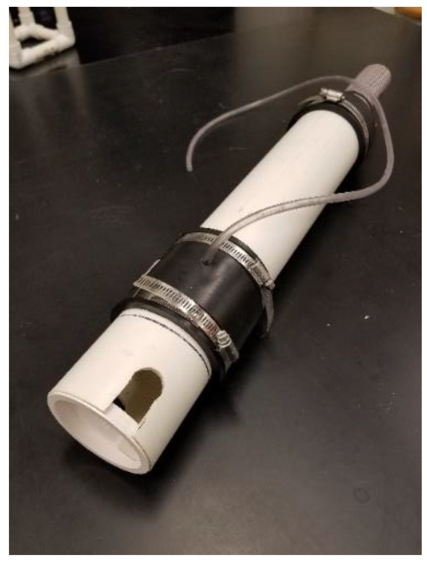
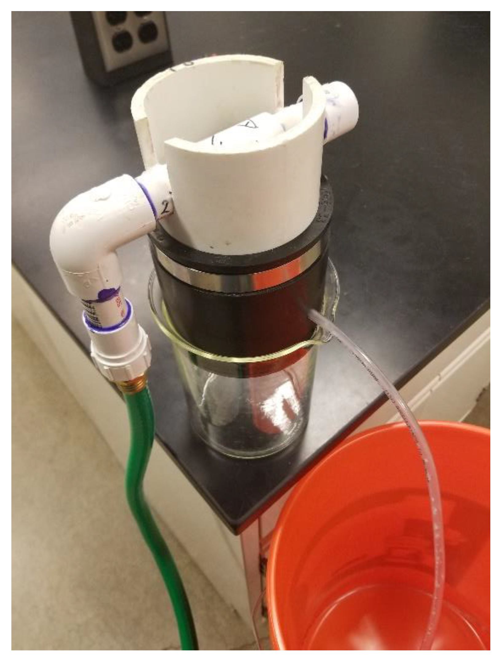
  • Assemble the soil column (Figure 1b). Insert the discharge tube into the funnel coupling and tighten. Hold two layers of window mesh taut across the end of the soil column shell and insert it into the funnel coupling and tighten. Place two layers of window mesh on the other end of the soil column shell, place the sidewall ring on the window mesh, then insert it into the bottom of the coupling. Insert the nozzle housing into the top of the coupling. Insert the knockout test cap into the top of the nozzle housing. Figure 4 shows the finished soil column component.

2.4. Assembly of Soil Column Stand

The soil column stand (Figure 5) was constructed using the materials in Table 2. This procedure constructs a stand for a single 7.62 cm (3 in) i.d. PVC of 30.48 cm (12 in) length. The stand can be altered to accommodate for soil columns of different diameters or lengths.
  • Measure, mark, and cut the 1.27 cm (0.5 in) o.d. PVC to the lengths and quantities shown for the upper leg, lower leg, and horizontal support with the PVC pipe cutter.
  • Assemble the PVC and connectors (Figure 1c).
  • Loosen or tighten two hose clamps to approximately 7.62 cm (3 in) diameters. Zip-tie a hose clamp to the top three horizontal supports. Zip-tie the second hose clamp to the lower two horizontal supports. Figure 5 shows the finished soil column stand.

2.5. Mist Nozzle and Piping

The materials in Table 3 and this procedure construct a single 1 gph mist nozzle with piping. ACF Greenhouses mist nozzles with other flowrates are compatible with this design.
  • Measure, mark, and cut the 1.27 cm (0.5 in) o.d. PVC to the lengths and quantities shown for the piping with the PVC pipe cutter.
  • Assemble the PVC and connectors with PVC primer and PVC cement. Allow 24 h to dry.
  • Assemble the ACF Greenhouses 1 gph mist nozzle. Wrap the threads with Teflon tape. Screw the mist nozzle into the ACF Greenhouses mist tee. Attach the garden hose to the ACF Greenhouses swivel hose connector. Figure 6 shows the finished soil column mist nozzle and piping.

2.6. Complete Soil Column System

The complete soil column system (Figure 7) was constructed by combining all three components: the soil column, soil column stand, and mist nozzle and piping. The following procedure completes the construction of the soil column system and prepares it for use.
  • Place the bottom half of the soil column inside the stand by pushing the soil column shell, funnel coupling, and discharge tube between the stand’s lower legs.
  • Slide the soil column shell upwards through the hose clamps and tighten them at a height that leaves enough space for a beaker under the discharge tube. Place a beaker under the discharge tube. Use a level to adjust the soil column to be vertical.
  • Place the coupling on the soil column shell and tighten the hose clamp. Place the mist nozzle housing into the coupling and tighten the hose clamp.
  • Attach the garden hose to the swivel hose connector and water source. Line the mist nozzle up with the center of the soil column. Push the 1.27 cm (0.5 in) piping into the slots and 1.27 cm (0.5 in) diameter drilled holes in the nozzle housing. If the slots or holes in the mist nozzle housing are too small, lightly file for a snug fit. Place the knockout test cap on the nozzle housing.

2.7. Soil Collection

Two soils were chosen for testing the basic functionality of the system. One soil type was a large granular sand. QUICKRETE playground sand was separated with a 1.4 mm sieve. The fine sand particles that passed through the sieve were discarded to allow for a faster infiltration rate and since no large organic matter or gravel particles were retained in the 1.4 mm sand, a relatively uniform sand remained. The second soil type was a 131C2 Alvin fine sandy loam from eroded slopes of 5–10%. The Alvin was collected from a buffer zone near an agricultural field in Jasper County, IL, USA. Vegetation was removed from the soil surface and the top 15.24 cm (6 in) was collected and deposited into a 5-gallon bucket. The Alvin fine sandy loam was separated with a 4 mm sieve. Organic matter and particles 4 mm and larger were discarded.

2.8. Soil Packing

There are multiple techniques for soil packing such as dry, damp, and slurry packing. Dry and damp packing involve layering and compacting soil into the column repeatedly, with dry and damp soil respectively. In the slurry packing technique, the soil is either mixed with water before being added to the column or slowly added to a column filled with water with intermittent mixing [2]. This procedure will focus on dry packing.
For dry packing, Oliveira et al. (1996) [22] recommends depositing sand in layers of 0.2 cm, or approximately 0.08 in, and compacting with a metal pestle. The soil column shell and funnel coupling was removed from the flow-reduction cap housing and soil column stand. The 5 μm sand was taken from the capped glass containers and packed into the 30.48 cm (12 in) soil column in layers of 1.27 cm (0.5 in) depths and compacted with a stainless-steel pestle. The packed soil column shell and funnel coupling was then reconnected to the flow-reduction cap housing and soil column stand.
Corwin (2000) [10] packed a large lysimeter with an Ascalon sandy clay loam in increments of 0.5 cm or less with applications of water. Wetting-and-drying cycles were also utilized to encourage settling and compaction. Sandy clay loam is soil material with 20–35% clay, less than 28% silt, and 45% or more sand. Fine sandy loam is soil material with 30% or more fine sand and less than 30% very fine sand or 15–30% medium, coarse, and very coarse sand [23]. Due to the difference in soil composition between Ascalon sandy clay loam and Alvin fine sandy loam, Oliveira et al.’s (1996) [22] packing method was chosen due to the Alvin fine sandy loam being more similar to the sand in that study. The Alvin fine sandy loam and QUICKRETE sand was packed according to the recommendations of Oliveira et al. (1996) [19].

2.9. Testing Mister Nozzle Flowrates

Several 1 gph mister nozzles were purchased from ACF Greenhouses. Four were initially tested separately for flowrate. The mister nozzle threading was wrapped with Teflon tape and threaded into the ACF Greenhouses misting tee and connected to piping. The mister nozzle and piping were attached to a garden hose and water source. One minute of flow from the nozzle was collected in a 1000 mL beaker. Multiple trials consisted of repeatedly measuring the flowrate and drying the beaker.

2.10. Flow-Reduction Cap Flowrate

The flow-reduction cap is the main method of controlling the flowrate of water that enters the soil from the mist nozzle. The desired flowrate inside of the soil column is 1.52 in h−1, or approximately 2.934 mL min−1. This target rainfall intensity was chosen as the two-year average recurrence and 60-min duration rainfall intensity from the National Oceanic and Atmospheric Administration’s Precipitation Frequency Data Server’s Urbana IL station [24]. The flowrate output of the mist nozzle is 1 gph, or approximately 63.09 mL min−1. The goal of the flowrate testing is to cut the 1 gph flowrate down to a more likely rainfall intensity.
After soil column construction, the component made up of the coupling, coupling spacer, flowrate-reducing cap, overflow tube, mist nozzle housing, mist nozzle and piping, and garden hose was placed in a 1000 mL glass beaker (Figure 8). After the garden hose and water source were connected and opened, it was confirmed that the mist was entering through all three of the raised holes of the flow-reduction cap and that the overflow tube was properly emptying the cap. It is also important to check that the droplets have enough spread to cover, or wet, the entire soil surface. The water from the overflow tube was collected in a waste bucket. The beaker was then emptied, dried, and placed back under the coupling. The nozzle misted through the flow-reduction cap for 10 min and the volume of the glass beaker was recorded.
The first measurements were taken with a flow-reduction cap with 0.381 cm (0.15 in) diameter raised holes. These holes yielded a flowrate that was under the target flowrate of 2.934 mL min−1. Additional flow-reduction caps were printed with larger hole diameters. New flow-reduction cap housings (Figure 3) were generated for each new flow-reduction cap. The new flow-reduction caps were tested with the same procedure.

2.11. Infiltration Time

To begin, the soil column system was tested without any soil to check for leaks or component failure. This was done with a 30.48 cm (12 in) column and 0.635 cm (0.25 in) raised hole diameter flow-reduction cap. The rainfall intensity entering the soil column is assumed to be the average flowrate through the 0.635 cm (0.25 in) flow-reduction cap, or 3.07 mL min−1. This rainfall intensity was deemed acceptable due to its proximity to the desired rainfall intensity of 2.934 mL min−1. The column system was assembled as described above with a 1000 mL beaker under the discharge tube. The overflow from the overflow tube was collected in a waste bucket.
The complete soil column system was then packed with soil as described above. The system was set to begin raining on the soil and continued to do so until the end of the experiment. The time required for water to pass completely through the soil column system was recorded. There were six trials, one for each column length and soil type. Six sets of soil column shells, coupling funnels, and discharge tubes were created to avoid cleaning and repacking the same soil columns multiple times. These three components were replaced for every new trial. Infiltration time was measured on soil column lengths of 7.62 cm (3 in), 15.24 cm (6 in), and 30.48 cm (12 in) for both the QUICKRETE sieved sand and the Alvin fine sandy loam (Figure 9).

3. Results

3.1. Design

The focus of this study was to construct a soil column system and evaluate its design and effectiveness. This study resulted in a closed, functional, bench-top soil column system with limited rainfall simulation capabilities. With the exception of the 3D-printer, it can be recreated without access to highly specialized tools. The 3D-printers, however, are becoming more widely accessible as costs continue to lower [25]. All of the other materials used in construction are widely available in hardware stores and online retailers.

3.2. Flowrate through Mist Nozzle and Flow-Reduction Cap

The flowrate of the ACF Greenhouses poly mist nozzles was advertised as 1 gph, or 63.09 mL min−1 for the 7.62 cm (3 in) i.d. column used in this study. The actual flowrates are recorded in Table 4.
Every nozzle had an output over the advertised flowrate, but had a difference of less than 10% in average flowrate between each other. Because every mist nozzle and flow-reduction cap must be tested together to confirm flowrate into the soil column, a slightly higher nozzle flowrate can be remedied by altering the design of the flow-reduction cap to have smaller raised holes that allow less water to pass into the soil column. The data in Table 5 demonstrates the flow-reduction cap’s ability to regulate flowrate.
A small difference in the flow-reduction cap’s raised hole diameter heavily impacts flowrate. The lowest attainable flowrate into the 7.62 cm (3 in) soil column appears to be around 0.803 in h−1, or 1.55 mL min−1 with a raised hole diameter of (0.15 in) (Table 5). Below this diameter, the hole becomes too small and water is not able to freely pass through. The highest attainable flowrate has not been determined; however, the flowrate could reach approximately 32.68 in h−1 if the mist nozzle’s full 63.09 mL min−1 flowrate entered the soil column. The information presented in Table 5 is particularly useful because it provides applicable information for those attempting to construct this design for the rainfall intensity they are targeting.

3.3. Infiltration Time

The time required for water to infiltrate the entire length of the soil column is presented in Figure 9. When comparing columns of the same length, a higher infiltration time suggests a lower infiltration rate. Similarly, a lower infiltration time suggests a higher infiltration rate. Collecting infiltration time data is intended to confirm the functionality of the soil column system with actual soil. However, trivial observations can be made regarding the infiltration times for each column length and type. For example, the QUICKRETE playground sand columns drained quicker at every soil column length. Comparing observations to well-known characteristics of soil and water interaction may suggest that the soil column system behaved as expected.

4. Discussion

4.1. Infiltration Time

As expected, the infiltration rate was higher for the QUICKRETE playground sand columns than the Alvin fine sandy loam. It is well known that wider pore spacing increases the rate of infiltration [26]. The playground sand was composed of larger-sized particles, had larger pore spacing, and therefore likely has a higher rate of infiltration than the smaller pore-spaced Alvin soil. Sentenac et al. (2001) [27] observed that larger particles have also been observed to increase sidewall preferential flow, and may have contributed to the playground sand’s shorter infiltration time. Fine soils with less porosity or pore space are also known to hold more water than coarse soils [26]. This may have attributed to the longer infiltration time of the Alvin fine sandy loam.
As the column length increased, the difference in infiltration rate between playground sand and Alvin fine sandy loam also increased. This may be due to the difference in infiltration rate compounding as column length increases. This would cause the infiltration time for the Alvin soil to continue to separate from the infiltration time of the playground sand.

4.2. Design Justification

4.2.1. Soil Column

Schedule 40 PVC was chosen primarily for its price and attainability. PVC is also well suited for use with ammonium, iron, dissolved organic bound nutrients, dissolved organic carbon, potassium, calcium, carbonate, nitrate, and sulfate [28]. Plastics such as PVC are relatively less rigid than other commonly used soil column shell materials. This prevents PVC from being viable for applications that require large soil columns. Because this design is for table-top use, the lesser rigidity of PVC is considered acceptable. The lack of rigidity also makes PVC more susceptible to preferential sidewall flow [2]. Rigidity of a material is important for structural integrity, strength, and to prevent disturbing the soil when the material flexes. Schedule 40 PVC has a minimum wall thickness of 0.33782 cm (0.133 in) and can withstand 3102.64 kPa (450 psi). Thicker PVC would be more rigid and be able to withstand higher pressures. Other downsides of plastics are their potential to adsorb trace metals [29,30] and absorb organic compounds [28]. Because the purpose of this study was simply to construct and test a soil column system design, the most manageable material was chosen. However, this soil column system design is compatible with other material types, so long as that material is compatible with rubber and PVC fittings and connectors. Because of the system’s modular design, the PVC soil column shell can simply be replaced with a different material soil column shell. Beware that the rubber funnel coupling on the outlet of the soil column will come into contact with the fluid and potential contaminants passing through the soil. Like every other material, rubber is more or less suitable for certain applications.
This soil column system was designed for use with a desired 7.62 cm (3 in) soil column diameter. The design can be modified to accommodate different soil column diameters. There are, however, unknown threshold limits for how small or large this design could be. The soil column stand is the main limiting factor in the latter case. The zip ties holding the hose clamps and soil column to the soil column stand would not be able to hold the weight of a large soil column. For smaller soil columns, the size would be limited by the mist nozzle and tee. For this design, the diameter of the soil column cannot be smaller than the 5.33 cm (2.1 in) length of the ACF mist tee. Bergström (2000) [12] and Lewis and Sjöstrom (2010) [2] recommend a soil column diameter to length ratio of 1:4 to limit sidewall flow. The initial 30.48 cm (12 in) soil column length and 7.62 cm (3 in) diameter matches this ratio. The other lengths of 7.62 cm (3 in) and 15.24 cm (6 in) were simply chosen for more variation in data. Soil column diameters of 1.905 cm (0.75 in) and 3.81 cm (1.5 in), for lengths 7.62 cm (3 in) and 15.24 cm (6 in) respectively, are compatible with the design if it is necessary to adhere to the ratio.
The coupling is crucial for this design because it contributes to its modularity. This increases its ease of use as well. The soil column stand, flow-reduction cap housing, and mist nozzle and piping can be reused. Only the soil column shell, funnel coupling, discharge tube, and window meshing need to be replaced with each new soil column sample. Loosening and tightening the hose clamps with a flat screwdriver allows the user to replace only a few parts while the rest of the system requires no preparation to be immediately ready for the next soil sample. The modular design also makes cleaning and storing the system easier. Rubber couplings are widely accessible and found in hardware stores in various sizes. Some soil column setups utilize pressure or suction to facilitate infiltration through soil and simulate more realistic conditions [2]. The rubber couplings are rated for 29.6475 kPa (4.3 psi). Suction is usually applied at the base of the soil column, so the soil column system may be compatible with a pressurized soil column procedure. More research and testing is required to confirm or deny.
The flow-reduction cap sits directly below the mist nozzle. Mist accumulates on the three raised holes and passes through the flow-reduction cap. The rest of the mist accumulates in the flat basin of the flow-reduction cap and drains through the overflow tube and into a waste container. The water that passed through the flow-reduction cap drips down onto a layer of two window mesh sheets. Water impacts the window mesh and splatters across the surface of the soil. Water also accumulates on the window mesh and drips to the soil surface that is 2.54 cm (1 in) below. The window mesh lessens water impact and acts as a barrier between contaminated soil and the flow-reducing cap.
The flow-reduction cap is the most unique aspect of this design (Figure 2). It was created specifically for this design to serve three intended purposes: to regulate water flowrate into the soil column, to separate the contaminated soil from the mist nozzle, and to help simulate rainfall. The flow-reduction cap has three raised holes that limit flowrate from the mist nozzle to the soil column. There are not many easily accessible nozzles that have a flowrate as low as the desired 2.934 mL min−1, or 0.047 gph. The smallest mist nozzle or dripper was 1 gph, so the flow-reducing cap was originally designed to fix the issue of large nozzle flowrates. Altering the size of the raised holes alters the flowrate into the soil column (Table 5). The remaining water that does not pass into the soil column pools in the basin at the bottom of the flow-reduction cap. There, a single hole routes the pooling water through the discard tube and out of the soil column. The raised holes prevent any of the pooling water from flooding into the soil column. The flowrate passing into the soil column can only be regulated when switching flow-reduction caps. Using raised holes of different diameters allows users to change flowrate between uses. Flowrate cannot be regulated while the soil column system is in use. Secondly, the flow-reduction cap separates contaminated soil from the mist nozzle housing and its two small openings that the mist nozzle piping fits into. Thirdly, the flow-reduction cap helps create a limited rainfall simulation. Mist accumulates in the raised holes and form into water droplets that roll down the angled underside of the flow-reduction cap. There are three raised holes because they spread the water droplets across more soil surface area. The angled underside under the raised holes further spread water droplets. This causes droplets to fall from two to three different places for each raised hole. Spreading water droplets with the flow-reduction cap gives a better representation of rainfall than a single mister or dropper could provide. Combined with the window meshing underneath, the flow-reduction cap also prevents the forming of depressions on the soil surface where drops consistently hit. The flow-reduction cap produced the most novel findings of this study. The flow-reduction cap was created specifically for this system, providing a method of altering flowrate. Because of the cap’s many functionalities, it is crucial for the success of this design. Its simple design makes it easily transferrable to other pre-existing soil column designs. Data compiled in Table 5 demonstrate the versatility of the cap and suggests that slight design modifications could tailor it for any application. Acrylonitrile butadiene styrene (ABS) was chosen as the print material because of its availability, price, and superior mechanical properties over similar options such as polylactic acid (PLA).
The mist nozzle housing sits on top of the flow-reduction cap and holds the mist nozzle in place. It was designed with two slots for the piping for easy deconstruction and access to the mist nozzle if it needs to be replaced or cleaned. Mist nozzles can, however, be difficult to clean and expensive to replace after every trial. The presence of the window mesh and flow-reduction cap helps by reducing the likelihood of nozzle contamination and therefore the likelihood of needing to replace or clean the nozzle. A knockout test cap covers the top of the mist nozzle housing and prevents mist from escaping.

4.2.2. Soil Column Stand

The soil column stand is designed to hold the soil column above a collection container. It was constructed out of schedule 40 PVC for price and accessibility. Two of many soil column stand designs are mentioned below. Sheppard’s (1997) [31] design most closely resembles the proposed soil column stands. Both have stands that are separate from the soil column and are primarily used with smaller diameter soil columns. Schlossberg and Karnok’s (2002) [4] design have a square Plexiglas base that makes it sturdier and better suited for larger columns. The flat base may also cause difficulties with drainage. As water and materials infiltrate towards the bottom of the soil column, they will have to travel horizontally through the soil to drain through the small tube in the center. Depending on how well the soil drains, it may only affect a very small range of depths at the bottom. Schlossberg and Karnok (2002) [4] prevent this by pushing the drainage tube further up into the soil column. Placing a layer of coarse sand or gravel beneath the soil medium of interest would also prevent soil column flooding. This study’s proposed design has window mesh and funnel coupling at the bottom of the soil column. This leaves open air beneath the soil that doesn’t restrict water flow. The 30.48 cm (12 in) length design proposed in this study also fits snugly within a biosafety cabinet. Schlossberg and Karnok’s (2002) [4] design may not fit because it requires more vertical space.
The height and width of the soil column stand is designed specifically for soil columns of 7.62 cm (3 in) diameter and 30.48 cm (12 in) length. Soil columns of 7.62 cm (3 in) and 15.24 cm (6 in) lengths were used with this soil column stand design with some small changes. The upper legs were shortened so that the hose clamps could tighten around the soil column shell. For soil columns under 7.62 cm (3 in) in length, this soil column design will only work with one hose clamp.
The soil column stand has some design constraints. The soil column is supported entirely by hose clamps and zip ties and the stand’s weight limits have not been determined. For larger soil column sizes, Schlossberg and Karnok’s (2002) [4] design could inspire this study’s design to trade the funnel coupling and discharge tube for a flat base. The soil column design is also incompatible with soil columns under 7.62 cm (3 in) in length. For these lengths, the vertical distance between the hose clamps on the stand would be too large to hold the soil column. In this case, a single hose clamp would be necessary.

4.2.3. Mist Nozzle and Piping

The mist nozzle and piping were designed to fit directly into the mist nozzle housing. Because the slots are slightly smaller than the circular notches in the mist nozzle housing, the piping should fit securely in the notches. This design feature simplifies mist nozzle maintenance and replacement. The PVC piping connections were secured with PVC cement for a tight seal. The mist nozzle was chosen for its low flowrate, price and accessibility, and relatively narrow spray pattern [32,33].
The overall design of the mist nozzle and piping has some sizing limitations. Because of the spread of the mist nozzle, it would not cover the entire area of the soil surface for a large soil column. In this circumstance, a change in piping design to accommodate multiple mist nozzles or a different nozzle with larger spread would be necessary. This design also has a lower size limit; the poly misting tee will not fit in a soil column of less than 5.33 cm (2.1 in) in diameter.

5. Conclusions

The primary focus of this research was to construct and demonstrate a method of testing the transfer of harmful materials in a soil column. The procedure of running water through the soil column system demonstrates its potential as a functional soil column. Its closed design suggests specialized application for research with pathogens that are harmful to humans. The modularity of the design allows its parts to be reused with different samples and little transitional preparation. Its modular versatility also guarantees improvement and modification to fit multiple experimental design needs. The pseudo-rainfall simulator offers limited realism due to the lessened soil impact but provides an evenly spread, raindrop pattern. The proposed soil column system is currently a functional prototype with the potential for a wide range of uses. The authors recommend this system for use with studies that involve hazardous components and require continuous water addition. Pathogen studies that require a biosafety cabinet are typically small-scale with soil columns of just a few centimeters in diameter. This is due to the limited space and difficulty of simulating rainfall within a biosafety cabinet. When a biosafety cabinet is required, this system provides a valuable alternative to conventional systems because of its built-in capacity for rainfall simulation while still maintaining a size that fits within a biosafety cabinet. Additional research into increasing its operational size range and the introduction of instrumentation, sensors, and sampling apparatus will improve the design and make it more applicable to current research needs.

Author Contributions

Conceptualization, M.R.M., N.H.O. and P.C.D.; Data curation, M.R.M.; Formal analysis, M.R.M.; Funding acquisition, M.L.G., W.H.W. and P.C.D.; Investigation, M.R.M.; Methodology, M.R.M., N.H.O. and P.C.D.; Project administration, P.C.D.; Resources, P.C.D.; Supervision, N.H.O. and P.C.D.; Writing—original draft, M.R.M.; Writing—review and editing, N.H.O., M.L.G., W.H.W. and P.C.D.

Funding

This work was funded in part by a University of Illinois, College of Agricultural, Consumer, and Environmental Sciences (ACES) Future Interdisciplinary Research Explorations (FIRE) grant.

Acknowledgments

The authors would like to thank Alisha Weatherspoon for assistance with system testing.

Conflicts of Interest

The authors declare no conflict of interest.

References

  1. Howell, T.A. Lysimetry. In Encyclopedia of Soils in the Environment; USDA Agricultural Research Service: Bushland, TX, USA, 2005; pp. 379–386. [Google Scholar]
  2. Lewis, J.; Sjöstrom, J. Optimizing the experimental design of soil columns in saturated and unsaturated transport experiments. J. Contam. Hydrol. 2010, 115, 1–13. [Google Scholar] [CrossRef] [PubMed]
  3. Butters, G.L.; Bandaranayake, W. Demonstrations in solute transport using dyes: I. Procedures and results. J. Nat. Resour. Life Sci. Educ. 1993, 22, 121–125. [Google Scholar]
  4. Schlossberg, M.J.; Karnok, K.J. Use of transparent columns for demonstrating water movement in golf green root zones. J. Nat. Resour. Life Sci. Educ. 2002, 31, 1–4. [Google Scholar]
  5. Ngo, V.V.; Michel, J.; Gujisaite, V.; Latifi, A.; Simonnot, M. Parameters describing nonequilibrium transport of polycyclic aromatic hydrocarbons through contaminated soil columns: Estimability analysis, correlation, and optimization. J. Contam. Hydrol. 2014, 158, 93–109. [Google Scholar] [CrossRef] [PubMed]
  6. Gruber, A.K.; Shelton, D.R.; Pachepsky, Y.A. Transport and retention of manure-borne coliforms in soil. Vadose Zone J. 2005, 4, 828–837. [Google Scholar] [CrossRef]
  7. González, M.E.; Cea, M.; Medina, J.; González, A.; Diez, M.C.; Cartes, P.; Monreal, C.; Navia, R. Evaluation of biodegradable polymers as encapsulating agents for the development of a urea controlled-release fertilizer using biochar as support material. Sci. Total Environ. 2014, 505, 446–453. [Google Scholar] [CrossRef]
  8. Laird, D.A.; Fleming, P.; Davis, D.D.; Horton, R.; Wang, B.; Karlen, D.L. Impact of biochar amendments on the quality of a typical Midwestern agricultural soil. Geoderma 2010, 158, 443–449. [Google Scholar] [CrossRef] [Green Version]
  9. Schäfer, A.; Ustohal, P.; Harms, H.; Stauffer, F.; Dracos, T.; Zehnder, A.J.B. Transport of bacteria in unsaturated porous media. J. Contam. Hydrol. 1998, 33, 149–169. [Google Scholar] [CrossRef]
  10. Corwin, D.L. Evaluation of a simple lysimeter-design modification to minimize sidewall flow. J. Contam. Hydrol. 2000, 42, 35–49. [Google Scholar] [CrossRef]
  11. Lewis, J.; Sjöstrom, J. Optimizing the experimental design of unsaturated soil columns. In Proceedings of the 19th World Congress of Soil Science: Soil Solutions for a Changing World, Brisbane, Australia, 1–6 August 2010; pp. 1–6. [Google Scholar]
  12. Bergström, L. Leaching of agrochemicals in field lysimeters—A method to test mobility of chemicals in soil. In Pesticide/Soil Interactions; INRA: Paris, France, 2000; pp. 279–285. [Google Scholar]
  13. Feyereisen, G.W.; Folmar, G.J. Development of a laboratory-scale lysimeter system to simultaneously study runoff and leaching dynamics. Trans. ASABE 2009, 52, 1585–1591. [Google Scholar] [CrossRef]
  14. Chrysikopoulos, C.V.; Syngouna, V.I. Effect of gravity on colloid transport through water-saturated columns packed with glass beads: Modeling and experiments. Environ. Sci. Technol. 2014, 48, 6805–6813. [Google Scholar] [CrossRef]
  15. Oerke, E.C. Crop losses to pests. J. Agric. Sci. 2005, 144, 31–43. [Google Scholar] [CrossRef]
  16. Schijven, J.F.; Hassanizadeh, S.M. Removal of viruses by soil passage: Overview of modeling, processes, and parameters. Crit. Rev. Environ. Sci. Technol. 2000, 30, 49–127. [Google Scholar] [CrossRef]
  17. Camobreco, V.J.; Richards, B.K.; Steenhuis, T.S.; Peverly, J.H.; McBride, M.B. Movement of heavy metals through undisturbed and homogenized soil columns. Soil Sci. 1996, 161, 740–750. [Google Scholar] [CrossRef]
  18. Wehrhan, A.; Kasteel, R.; Simunek, J.; Groeneweg, J.; Vereecken, H. Transport of sulfadiazine in soil columns—Experiments and modelling approaches. J. Contam. Hydrol. 2006, 89, 107–135. [Google Scholar] [CrossRef] [PubMed]
  19. Rabølle, M.; Spliid, N.H. Sorption and mobility of metronidazole, olaquindox, oxytetracycline and tylosin in soil. Chemosphere 2000, 40, 715–722. [Google Scholar] [CrossRef]
  20. GrabCAD Community. Available online: https://grabcad.com/library/flow-reduction-cap-1 (accessed on 7 March 2019).
  21. ACF Greenhouses. Available online: http://www.littlegreenhouse.com/accessory/mist.shtml (accessed on 7 March 2019).
  22. Oliviera, I.B.; Demond, A.H.; Salehzadeh, A. Packing of sands for the production of homogeneous porous media. Soil Sci. Soc. Am. J. 1996, 60, 49–53. [Google Scholar] [CrossRef]
  23. Cornell University Cooperative Extension of Suffolk County. General Soil Information and Specs. Available online: https://s3.amazonaws.com/assets.cce.cornell.edu/attachments/3341/general_soil_info_and_specs.pdf?1413396358 (accessed on 30 January 2019).
  24. Precipitation Frequency Data Server—NOAA. Available online: https://hdsc.nws.noaa.gov/hdsc/pfds/ (accessed on 30 January 2019).
  25. Ngo, T.D.; Kashani, A.; Imbalzano, G.; Nguyen, K.T.Q.; Hui, D. Additive manufacturing (3D printing): A review of materials, methods, applications and challenges. Compos. Part B Eng. 2018, 143, 172–196. [Google Scholar] [CrossRef]
  26. Ball, J. Soil and Water Relationships. Available online: http://kbsgk12project.kbs.msu.edu/wp-content/uploads/2011/09/Soil-and-Water-Relationships.pdf (accessed on 30 January 2019).
  27. Sentenac, P.; Lynch, R.J.; Bolton, M.D. Measurement of a side-wall boundary effect in soil columns using fiber-optics sensing. Int. J. Phys. Model. Geotech. 2001, 1, 35–41. [Google Scholar] [CrossRef]
  28. Weihermüller, L.; Siemens, J.; Deurer, M.; Knoblauch, S.; Rupp, H.; Göttlein, A.; Pütz, T. In situ soil water extraction: A review. J. Environ. Qual. 2007, 36, 1735–1748. [Google Scholar] [CrossRef]
  29. Rais, D.; Nowack, B.; Schulin, R.; Luster, J. Sorption of trace metals by standard and micro suction cups in the absence and presence of dissolved organic carbon. J. Environ. Qual. 2006, 35, 50–60. [Google Scholar] [CrossRef] [PubMed]
  30. Wenzel, W.W.; Sletten, R.S.; Brandstetter, A.; Wieshammer, G.; Stingeder, G. Adsorption of trace metals by tension lysimeters: Nylon membrane vs. porous ceramic cup. J. Environ. Qual. 1997, 26, 1430–1434. [Google Scholar] [CrossRef]
  31. Sheppard, S.C. Toxicity testing using microcosms. In Soil Ecotoxicology; CRC Press: Boca Raton, FL, USA, 1997; pp. 345–373. [Google Scholar]
  32. Davidson, P.C. Characterization of Pathogen Transport in Overland Flow. Ph.D. Thesis, Department of Agricultural and Biological Engineering, University of Illinois at Urbana-Illinois, Urbana-Champaign, IL, USA, 2010. [Google Scholar]
  33. Davidson, P.C.; Kuhlenschmidt, T.B.; Bhattarai, R.; Kalita, P.K.; Kuhlenschmidt, M.K. Effects of soil type and cover condition on Cryptosporidium parvum transport in overland flow. Water Air Soil Pollut. 2014, 225, 1882–1893. [Google Scholar] [CrossRef]
Figure 1. (a) The complete soil column system composed of three components: (b) the soil column, (c) the soil column stand, (d) the soil column mist nozzle and piping.
Environments 06 00033 g001aEnvironments 06 00033 g001b
Figure 2. The flow-reduction cap was designed in Autodesk® Inventor® to limit the 1 gph flowrate of the mist nozzle to near the desired 2.934 mL min−1 rainfall rate, assist in rainfall simulation, and separate contaminated soil from the mist nozzle. The three raised holes prevent standing water in the cap from entering the soil column and allow water from the mist nozzle to continue downwards towards the soil column. The single hole in the flat basin of the cap connects to a vinyl discharge tube that removes standing water as it accumulates in the cap.
Environments 06 00033 g002
Figure 3. Flow-reduction cap housing. The flow-reduction cap housing consists of the coupling, coupling spacer, flow-reduction cap, and discharge tube. A bead of silicone caulk will be applied around the top of the coupling spacer that touches the lip of the flow-reduction cap.
Environments 06 00033 g003
Figure 4. The constructed soil column.
Environments 06 00033 g004
Figure 5. The constructed soil column stand.
Environments 06 00033 g005
Figure 6. The constructed soil column mister nozzle and piping.
Environments 06 00033 g006
Figure 7. The complete soil column system.
Environments 06 00033 g007
Figure 8. The experimental setup for determining flowrate through the flow-reduction cap.
Environments 06 00033 g008
Figure 9. The infiltration time of water through 3, 6, and 12 inches of soils Alvin fine sandy loam and QUICKRETE playground sand.
Environments 06 00033 g009
Table 1. The following is a complete parts list for the soil column portion of the complete soil column system, as shown in Figure 1b.
Part NameMaterialSizing SpecificationsQuantity
Soil column shellPVCi.d.: 7.62 cm (3 in)Length: 33.02 cm (13 in)1
Coupling spaceri.d.: 7.62 cm (3 in)Length: 5.08 cm (2 in)1
Nozzle housingi.d.: 7.62 cm (3 in)Length: 7.62 cm (3 in)1
Knockout test capo.d.: 7.62 cm (3 in)1
Overflow tubeVinylo.d.: 0.635 cm (0.25 in)Length: 147.32 cm (58 in)1
Discharge tubeo.d.: 3.81 cm (1.5 in)Length: 15.24 cm (6 in)1
Flow-reduction cap3D-printed ABSSee Figure 21
Screen meshPlastic18 × 16 [a]Diameter: 10.16 cm (4 in)4
Sidewall ringPolycarbonatei.d.: 6.35 cm (2.5 in)o.d.: 8.89 cm (3.5 in)1
Funnel couplingRubberi.d.: 3.81 cm (1.5 in) to 7.62 cm (3 in)1
Couplingi.d.: 7.62 cm (3 in)1
[a] Mesh size. Denotes the number of rows and columns of holes within 1 sq. in.
Table 2. The following is a complete parts list for the soil column stand portion of the complete soil column system, as shown in Figure 1c.
Part NameMaterialSizing SpecificationsQuantity
Lower legPVCo.d.: 1.27 cm (0.5 in)Length: 31.115 cm (12.25 in)4
Upper legLength: 7.62 cm (3 in)4
Horizontal supportLength: 8.89 cm (3.5 in)9
Tee connectori.d.:1.27 cm (0.5 in)4
90° elbow connector2
3-way connector6
Hose clampStainless steelDiameter: 7.62 cm (3 in)2
Zip tiesPlasticLength: 15.24 cm (6 in)6
Table 3. The following is a complete parts list for the soil column mist nozzle and piping portion of the complete soil column system, as shown in Figure 1d.
Part NameMaterialSizing SpecificationsQuantity
PipingPVCi.d.: 1.27 cm (0.5 in)Length: 6.35 cm (2.5 in)3
90° elbow connectorPVCi.d.: 1.27 cm (0.5 in)1
Tube end capPVCi.d.: 1.27 cm (0.5 in)1
ACF Greenhouses [a] swivel hose connectorPVC1.905 cm (0.75 in) f screw to 1.27 cm (0.5 in) f slip1
ACF Greenhouses misting teePVCi.d.: 1.27 cm (0.5 in)1
ACF Greenhouses poly mist nozzlePlastic1 gph1
Hose clampStainless steelDiameter: 10.16 cm (4 in)1
Garden hoseRubber1.905 cm (0.75 in)1
[a] ACF Greenhouses parts were purchased from http://www.littlegreenhouse.com/accessory/mist.shtml [21].
Table 4. Flowrate (mL min−1) of four ACF Greenhouses poly mist nozzles.
NozzleTrial
12345678910Ave.
169.569.970.070.169.070.070.269.969.069.169.7
275.075.075.074.775.074.374.875.374.474.874.8
367.768.468.969.068.567.967.068.968.168.068.2
472.373.273.573.673.072.273.073.972.972.173.0
Table 5. Flowrate (mL min−1) through flow-reduction cap.
Flow-Reduction Cap Size (in) [a]Trial 1Trial 2Trial 3Ave
0.151.51.551.61.55
0.202.352.22.12.22
0.253.23.12.93.07
[a] The flow-reduction cap size refers to the diameter of each of the three raised holes that allow mist to pass through and into the soil column.

