Article

Flume Experiment on Flow Transition and Water Cushion Formation by Optimal Vegetation on a Mound Behind a Coastal Dike and Its Impact on Reducing the Flow Energy

1
Department of Mathematics, Faculty of Science, University of Rajshahi, Rajshahi 6205, Bangladesh
2
Graduate School of Science and Engineering, Saitama University, 255 Shimo-okubo, Sakura-ku, Saitama 338-8570, Japan
3
Department of Resilient Society, Research Center for Social Transformation, Saitama University, 255 Shimo-okubo, Sakura-ku, Saitama 338-8570, Japan
4
Department of Social Infrastructure, Infrastructure Managemant Division, NiX Japan Co., Ltd., Tokyo 101-0031, Japan
*
Author to whom correspondence should be addressed.
Geosciences 2025, 15(7), 243; https://doi.org/10.3390/geosciences15070243
Submission received: 15 February 2025 / Revised: 1 June 2025 / Accepted: 23 June 2025 / Published: 29 June 2025

Abstract

Standalone tsunami defense structures have demonstrated limitations in mitigating wave energy during the 2011 Japan tsunami. In order to mitigate future tsunamis in Japan, multi-layered protective mechanisms have been suggested or implemented after the incident. These include heightening the destroyed or existing embankment with concrete or stones, protecting embankments with concrete blocks, compacting the landward soil, elevating the ground following the coastal embankment, and incorporating green belts. Despite extensive research on the mitigation effects of such multiple countermeasures, the optimal structural configuration remains uncertain. In this study, we evaluated the performance of a multiple mitigation system consisting of a landward forest (F) on an elevated mound (M) following a seaward embankment (E) under a range of supercritical flow conditions using a flume experiment. Several mound heights and lengths were selected to determine the optimum mound for installing the forest. The combination of E and F of 12 rows of trees on M with a minimum height of 1.8 cm (Case EMFR12) created the greatest water cushion depth between E and M. When M was positioned without F, the water cushion between E and M was created by raising the height of the mound rather than its length. Conversely, a mound with a minimum height and length with a forest was found to be effective in creating the largest water cushion and maximum reduction of the flow energy. The highest energy reduction was between 45 and 70% in this experiment. These findings provide useful insights for developing multiple tsunami mitigation strategies that combine artificial and natural approaches.

1. Introduction

Structural and natural measures have been practiced to mitigate the impact of tsunamis over the last several decades. Coastal vegetation has been considered an ecosystem-based disaster risk reduction technique that is not only environmentally friendly but also economically viable. Because of its numerous applications, including lowering the destructive fluid force and energy, trapping debris, and creating soft-landing areas, it is acknowledged for tsunami mitigation techniques [1,2,3]. On the other hand, engineered countermeasures, such as coastal dikes, sea walls, embankments, and tsunami breakwaters, are effective in reflecting tsunami waves and protecting flood-borne areas from tsunamis; however, the implementation of these methods involves a huge investment [4]. However, the 2011 catastrophic Japan tsunami revealed the limitations of using single tsunami mitigation methods, whether natural or artificial [5,6]. A vast coastal forest of 70,000 trees was entirely damaged due to tree trunk breakage or being washed up, in which only one tree withstood the 2011 tsunami [7,8]. Another field survey showed that the tree trunks were unbroken and capable of trapping heavy debris where the trunk diameter was greater than 30 cm [9]. The landward side of the coastal embankment was eroded and swept away by the overtopping tsunami, and the damage was severe; thousands of buildings were washed away, damaged, or overturned by the overtopping tsunami [5,8,10]. Since the event, mitigation strategies have changed from single to line defense, which includes both soft (natural) and hard (artificial) solutions. The National Institute for Land and Infrastructure Management has planned or already started building new multi-layered defense systems for future tsunami mitigation techniques in Iwate, Miyagi, and Fukushima Prefectures in Japan [4,5,7]. These include heightening the see walls and coastal dykes, forested embankments, dunes with vegetation, evacuation hills covered with vegetation, canals, and elevated roadways and railroads [7,10,11].
Researchers are increasingly interested in multiple defense strategies. Wave inundation and energy can be reduced by a moat behind a coastal dike, followed by vegetation. In this case, the thick vegetation provided optimum reduction of overtopped tsunami energy [12]. In recent decades, researchers have demonstrated that physical models, such as seawalls, embankments, and canals, are useful for mitigating the adverse impacts of tsunamis [7,13]. Nevertheless, implementing such structural solutions is expensive and may not be financially feasible for developing countries[14]. Recent studies have shown that a hybrid defense system composed of an embankment, moat, and vegetation forest reduces tsunami energy by forming a submerged hydraulic jump within and behind the system [14]. In addition, the hydraulic jump location can be controlled to minimize the damage to structures from erosion [5,15]. However, constructing a double layer of vegetation is a challenging task and sometimes not possible because the trees require sufficient space to grow, enough sunlight is required to survive the trees in the bottom layer, and forest management is very complex.
When a tsunami faces multiple obstructions, the flow structures become complex, which is a major concern for their sustainability, in addition to the mitigation of tsunami energy [4,5,16,17]. Extensive research is essential to explore flow phenomena before implementing such methods. However, research on flow phenomena in multiple tsunami defense systems is not sufficient.
In multiple defense systems for future tsunamis, the construction of mounds with soil, tsunami-born wood, and concrete debris is ongoing to provide the maximum root anchorage of the trees on the mound, which is followed by coastal seawalls or concrete dikes [7]. The trees on the mound can provide additional resistance to overtopping tsunami waves. However, extensive research is essential to explore the flow phenomena before implementing such methods because when a tsunami faces multiple obstructions, the flow structures become complex, which is a major concern for their sustainability, in addition to the mitigation of tsunami energy [16,17]. Research on flow phenomena in such multiple tsunami defense systems is limited. According to recent research, a densely vegetated mound behind an embankment raised the flow depth inside the structures and substantially decreased the flow energy. Although it is challenging to build a dense forest in the field, several studies have demonstrated that a thick emergent forest may efficiently minimize tsunami energy because of its great resistance to flow [9,12,18]. However, the dense forest was flattened and eroded by large waves [3,9]. In addition, the trunk diameter becomes smaller and more vulnerable to breakage when trees grow densely [3,19]. In contrast, larger trees with a higher trunk diameter are better at capturing heavy debris, and breakage can be minimized [9,19].
This study conducted a flume experiment of a multiple protection system consisting of a seaward embankment and landward forest on an elevated mound, taking into account the aforementioned restrictions. The objective of this study was to maximize resistance against overtopping flow by optimizing the forest configuration on an elevated mound. To achieve this, several mound heights and widths were examined to determine the optimal mound dimensions. Trees were arranged at a moderate density in several rows with constant spacing between individual trees. The findings of this study are expected to aid in the design of future multiple defense systems against large tsunamis.

2. Materials and Methods

2.1. Flume Characteristics and Flow Conditions

This study was carried out in a 14 m long, 0.5 m wide, and 0.7 m high glass-sided open channel at Saitama University in Japan. A non-erodible (fixed) smooth wooden board was placed on the flume bed to avoid frictional losses. The Froude values (Fr = u/√(gh), where u is the depth-averaged velocity (m/s) and g is the gravitational acceleration (m/s2)) were estimated to vary from 1 to 1.5 in the Sendai Plain, Settai, and Taro of Japan during the 2011 tsunami [20]. This range was considered in the experiments. A fixed flume bed slope with a gradient of 1/200 was set to achieve supercritical flow conditions (Fr > 1) considering an actual tsunami inundation. A flow-circulating pump was set at the inlet of the flume. It was connected to a PC utilizing flow measurement software (Hydra 2.01) to maintain a quasi-steady flow of different discharges. A honeycomb-type screen and smoother were set at the inlet to absorb fluctuations. Another discharge measuring method, a triangular notch, was installed at the end of the flume to ensure accurate discharge measurements. Different discharges were set to achieve the considered range of the Froude values. Water level fluctuations were not observed before the placement of the models. The streamwise velocity of the flow was measured using a particle image velocimetry (PIV) system (Green Laser Sheet 200 m/G, Kato Koken Co. Ltd., Kanagawa, Japan) with 30 s and 20 Hz sampling frequencies. The velocity measurement from the PIV system was validated with another measurement using an Electromagnetic Flow Meter, and the error was within 2%. Two measurement systems, video analysis and a movable point gauge (KENEK Co. Ltd., Tokyo, Japan), were used to measure the water depths along the centerline throughout the flow and then averaged to obtain the flow depths. Six initial supercritical flow conditions of Fr = 1.01, 1.29, 1.44, 1.49, 1.52, and 1.56 were set before placing the compound defense models.

2.2. Physical Model of the Mitigation System

For the experimental models, a physical model scale of 1/100 was used. In order to mitigate future tsunamis, a new system of dikes was built along the coast of Iwate, Fukushima, and Miyagi Prefectures in Japan after the 2011 tsunami. The proposed height of the sea dikes in Koizumi, Miyagi Prefecture, is approximately 14.7 m. This includes the restoration and/or elevation of existing coastal dikes [7,21]. The embankment model was chosen for this investigation because it is sufficiently high and was designed for large tsunamis in the future. The newly installed and/or proposed seawalls or coastal embankments are made of stone, concrete structures, and a combination of soil covered by concrete blocks [4,7,8].
Considering the non-erodible structure of the embankment, a wooden E model measuring 14.5 cm in height (EH) was used for this experiment considering the real embankment height of 14.5 m in Iwate Prefecture, Japan. A slope of 1:2 and a crest with a width of 6 cm were selected for this experiment (Figure 1a). To examine the flow dynamics, non-erodible mounds of four heights and three lengths were constructed using wooden planks. The following table presents the experimental cases in this study.
In the 2011 tsunami, the trees in the coastal region with trunk diameters > 40 cm were found to withstand the impact of tsunami waves, and the trunks were not broken when the trunk diameter was >40 cm. Trees with larger trunk diameters have a lower tree density (large spacing between trees) [22]. Another study showed that trees with larger trunk diameters (>30 cm) were found to be unbroken and effective in trapping tsunami-borne heavy debris, floating boats, and ships [9,19]. This study considered a trunk diameter of 40 cm, taking into account the nonbreaking condition of trees to provide a trapping function where the canopy height is comparatively higher than the inundating height. Thus, the trees in the forest model were simulated using wooden cylinders with a height of 18 cm and a diameter (d) of 0.4 cm at a 1:100 scale. A sparse arrangement of trees was considered (S/d = 2.5, where S is the space between neighboring cylinders in the cross-stream direction) in the model (Figure 1b). Staggered or zigzag arrangements provide irregularities against the flow and reflect the tsunami wave, providing enhanced resistance [23]. Taking into account the optimum resistance from the forest, the cylinders were mounted in a staggered arrangement on a wooden board that filled the entire width of the flume (Figure 1b). The number of rows of trees was varied while maintaining a similar arrangement of trees to obtain the optimum forest model for M against overtopped flow. The number of rows was chosen to be 4, 7, and 12 for the forest model over the mound.
The tsunami caused large erosion landward when it overtopped the coastal embankment, where the scoured length varied from 4 to 31.78 m from the landward toe [24,25]. The scour length and depth increase with increasing momentum and energy heads of the overtopping tsunami [4]. Therefore, considering the use of land, scour phenomena, and creation of the water cushion between E and M, the mound models were placed 50 cm downstream of E for the elevated embankment. Considering the open gap (G) between the E and M, three mound lengths (ML) and heights (MH) were chosen (Table 1) to determine the optimum dimension of M in this experimental facility. The chosen number of tree rows was fixed for all selected mound heights. Figure 1a shows a schematic of the experimental setup. After placing the E model against the selected Fr values, six non-dimensional over flow depths (hc = 0.1, 0.16, 0.2, 0.26, 0.34, and 0.44; where hc = hc/EH, hc is the critical flow depth on the embankment crest) were obtained. Table 1 provides the details of the experimental setup. The height and length of E (EH and EL) and the open gap (G) between E and M remained constant in this study.

2.3. Parameters Used in This Study

The water depths were measured from the top of the embankment in Section 1 to the downstream Section 2, and the velocity was measured using PIV in Section 2. This study considered five non-dimensional parameters based on the objective and experimental models. These are the Froude number Fr, non-dimensional critical overflow depth hc (=hc/EH), and depth of the water cushion in the gap between the E and F models hg (=hg/MH, where hg represents the water cushion depth, which is obtained by averaging the water depth h2 measured in Section 2). The relative mound height MH (=MH/EH) and length ML (=ML/G) were also taken into account.
To evaluate the tsunami mitigation effect of the considered hybrid defense system, this study evaluated the percentage of energy reduction ΔE [%] downstream of the compound defense system as follows [26,27]:
E 1 = h 1 + α u 1 2 2 g
E 3 = h 3 + α u 3 2 2 g
  Δ E   % = E 1 E 3 E 1 × 100
where E1 and E3 are the energy heads, h1 and h3 are the measured flow depths, and u1 and u3 are the velocities at Section 1 and Section 3, respectively, as shown in Figure 2a. The parameter α is the energy coefficient, which changes with variations in the channel and velocity distribution along the flow. Because this study used a uniform cross-section of the channel with a fixed discharge, the parameter value was assumed to be a constant value of 1, as in a previous study [12,26].

3. Results

3.1. Flow Characteristics in the Experiments

3.1.1. Hydraulic Jump

Under these experimental conditions, the flow faced different geometrical shapes of a steep upstream slope of E, a nearly horizontal flume bed, an elevated horizontal bed of a mound, and a nearly horizontal flume bed in the downstream. In such a rectangular prismatic channel, various flow configurations, such as hydraulic jumps, exist and are categorized based on the place of generation [16,17]. A jump is considered a regular or A-jump when it occurs on a downward-facing slope. Type B-jump occurs when a jump is partially on the upstream and downstream slopes, and type C-jump is classified if it partially covers the upstream and downstream slopes [16,17,28]. Figure 2 shows a schematic of the jump types observed in the experimental scenario (Type A and Type B), where hc is the overflow depth on the embankment crest, Pj is the position of the jump toe (distance from the front line of the forest model), hg is the average depth of the water cushion within the space between the E and F models, and E1 and E3 are the energy heads in Section 1 and Section 3, respectively.

3.1.2. Flow Structures Inside and Downstream of the Mitigation System

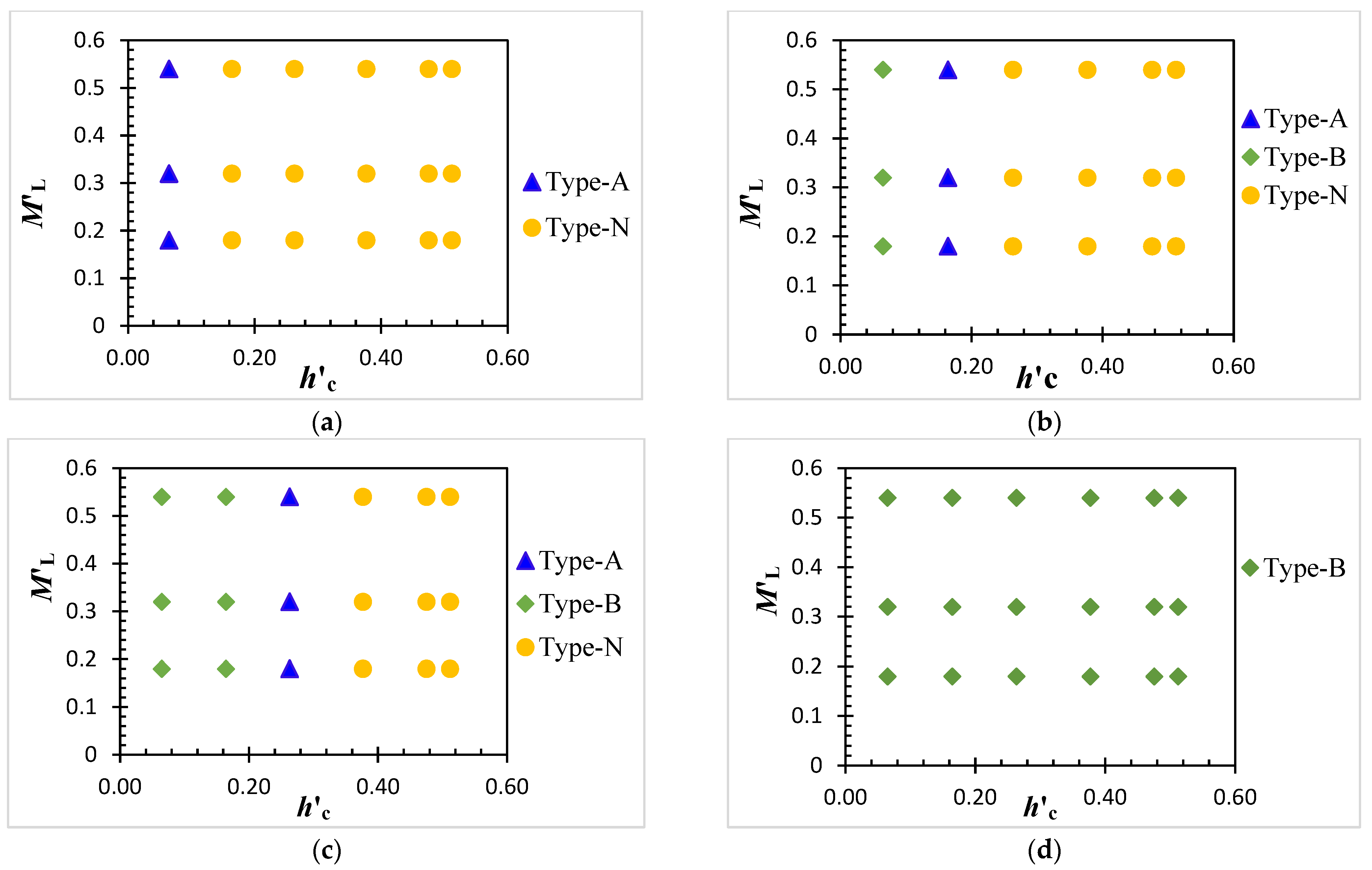
The flow structures varied with increasing MH but were independent of ML. Considering the formation of the water cushion and B-jump, the height of M was selected for mounting the forest on it, and the optimum forest and mound were obtained. Figure 3 shows a graph of the jump type within the length of G. The results showed that only an A-jump was formed for a minimum overflow depth of hc = 0.1 and a minimum mound height of MH = 0.12. The jump was swept out while hc increased (Figure 3a). The scenario is similar to that of EML1, EML2, and EML3 for this height of the mound. It is observed that increasing MH to 0.19 results in a B-jump for hc = 0.1 and an A-jump for hc = 0.16. However, the jump was washed away again with further increasing hc (Figure 3b). Similarly, B-jump is found against the flow of hc = 0.1 and hc = 0.16, A-jump is formed for hc = 0.26, and no jump (Type-N) is formed for the higher value of hc when the mound height is raised to MH = 0.25 (Figure 3c). In contrast, Type B-jump was formed and became stable against all values of hc while elevating the mound height further (MH = 0.37) (Figure 3d). The mound length did not affect the change in flow structure for a specific height of the mound.
In contrast, the flow structure variation was accelerated in the M with F forest cases. The M of minimum length (ML = 0.12) containing the simple forest (Case-EMFR4) was found to be effective in changing the jump type. For mound heights MH = 0.12 and 0.19, increasing hc changed the flow type from B to A and then to N when the parameter value was increased further (Figure 4a and Figure 5a,b). Even if the jump was swept out in these cases, a nappe flow was formed because of the forest. When the MH was increased to 0.25, the jump did not wash out but transformed from type B to A when hc became the highest in this experimental flow range (Figure 4a). Figure 4b shows that the jump was maintained in gap G for Case-EMFR7. In the minimum of MH, type A jumps are mostly formed for hc ≥ 0.16, whereas type B jumps are observed only for hc = 0.06. In Case- EMFR12, a type B jump was formed and remained stable regardless of the MH and hc values (Figure 4c). Even if the jump was washed out in some cases of EMF, it contributed to increasing the water depth downstream (Figure 4a and Figure 5c).
The flow structures in open gap G are strongly related to the mound height and forest cover. The Type B jump remained stable while reaching MH to 0.37 (Figure 3d and Figure 5c). Thus, the effect of forests on the jump variation in G could not be found in this case. A recent study showed that increasing the energy head caused scouring at the landward toe of the coastal levee, which damaged the structure [4,5,24]. Therefore, incorporating forests on this mound might increase the water level in G, which could enhance the energy head and affect the downstream. Considering this phenomenon, the forest over this mound was ignored. The effect of increasing the mound height is presented in Section 3.3. However, forest over the mound was found to be effective in changing the flow structure in G and downstream while decreasing the MH.

3.2. Water Cushion in the Gap

Implementing M downstream of E created a water cushion between these two structures. Figure 6 shows the average water depths relative to MH. Flow depths (h2) were measured from E to M at intervals of 2–5 cm, considering surface variation. The hg value was obtained by averaging h2 values. It was observed that hg reached a higher value, and a water cushion was created for the minimum hc when only the mound was implemented. The parameter value decreased significantly with increasing hc and then slightly increased with further increasing hc, but the water cushion was swept away. The scenario remained similar for MH = 0.12 and MH = 0.19 in Case-EMFR4 (Figure 6a,b). However, hg increased by around 1.5–6.7 times the corresponding MH, and the cushion became stable in Case-EMFR7 and Case-EMFR12 for all MH. Figure 6 shows that Case-EMFR12 produced the maximum water cushion for the selected range of MH. The maximum value was about 6.7 in this case for MH = 0.12. The parameter value slightly decreased and dropped to about 4 when MH. A decreasing trend of hg with increasing MH was also observed for the other cases. Therefore, the cushion depth relative to the mound height decreased with an increase in the mound height.
The hg value was found to be strictly related to the hydraulic jump. The formation of a B-jump increased the depth of the cushion compared to the A-jump. Because the entire B-type jump was formed in Case-EMFR12 for all values of MH, this case provided the maximum hg among the experimental cases. Although increasing the ML without a forest was not found to be effective in changing the overtopped flow structure, it provided space to increase the forest length, which was found to be more effective in producing and stabilizing the hydraulic jump and yielding the water cushion.

3.3. Reduction of the Flow Energy

This study evaluated the performance of a multiple mitigation system by estimating the energy reduction of the overtopped flow through the system. The energy reduction was calculated using Equation (3), and the results are shown in Figure 7. The energy reduction in all the experimental cases was around 70% for hc = 0.1. The reduction percentage of ΔE decreased rapidly with increasing hc and dropped to 20%, around 20–25%, and around 25–30% for MH = 0.12, MH = 0.19, and MH = 0.25, respectively, in the EM cases (Figure 7). We found that the differences in energy reduction were almost similar, with a minimum of MH, and varied from 1 to 3% for higher values of MH with respect to increasing ML. Thus, the ML was not effective in reducing the energy head when the mound contained no forest.
However, the energy reduction was higher in the EMF cases than in the EM cases. Figure 7a shows that increasing the hc value raised ΔE by about 1–5% in Case-EMFR7 and Case-EMFR12 compared to Case-EMFR4. In contrast, the differences in ΔE(%) among Case-EMFR4, Case-EMFR7, and Case-EMFR12 were about 1–2% (Figure 7a,b). The reduction amount decreased gradually with increasing hc and dropped by around 45%, 43%, and 41% for MH = 0.12, MH = 0.19, and MH = 0.25, respectively, in the EMF cases. The effect of increasing the number of tree rows on the mound increased the value of ΔE (%) from 1 to 5%, 1 to 2%, and 1 to 2% for the value of MH 0.12, 0.19, and 0.25, respectively. Thus, Case-EMFR12 was found to be effective in reducing the overtopped flow energy in this experiment.

4. Discussion

Flowing water on a steep slope carries excessive energy, which is disastrous to the transition zone and downstream region [21]. Due to overtopping, the landward side of the embankments was reported to be eroded, and some regions totally collapsed, which caused enormous damage to the downstream buildings, structures, and inland forests in the 2011 Japan tsunami [4,8,24]. Following the catastrophe, Japan has planned and started construction of elevated coastal dikes for future tsunami protection [5,7]. When a large tsunami occurs and overtops a high embankment, it may carry a large amount of energy downstream [4,5,17]. Therefore, it is necessary to reduce the high energy for the safety of the structure and the landward environment. This study revealed that when only a mound is implemented downstream of an embankment, the high energy flow can easily pass over the embankment downstream if there is no obstruction on the mound. This occurred because the mound slope only provided resistance to the high-energy overtopping flow. Thus, there is a chance that the mound will be eroded, and much damage could occur downstream.
The presence of a forest on the mound provided more resistance against the flow. A minimum number of tree rows was found to be capable of forming a hydraulic jump only for the lower range of overflow volume. Even if the simple forest was not capable of producing a hydraulic jump, a nappe flow was observed landward of the mound. Increasing the length of the mound provided space for increasing the number of rows of trees, which provided more resistance and formed a hydraulic jump inside G, even though the MH was very small. When the jump became stable (Type B), the water cushion also stabilized (Figure 5g,h). The maximum cushion depth relative to the mound height was produced in Case-EMFR12 for the minimum height of the mound, MH = 0.12 (Figure 6a). It was found to be reduced with increasing mound height. Therefore, increasing the mound length was found to be more effective in producing the hydraulic jump and water cushion in G than increasing the mound height. Following the 2011 Japan tsunami, a field study reported that several coastal embankments with forests behind them withstood the tsunami impact [29]. This occurs because the forest produces a water cushion between the embankment and the forest, and a submerged hydraulic jump is produced on the embankment [30]. Therefore, producing a water cushion behind the embankment using a mound with a forest could be beneficial for mitigation structures.
This study examined the reduction in overtopped wave energy through a forest on a mound as a secondary mitigation method. It was found that the energy reduction through the system mound with and without forest cases is almost similar for a very small overtopping flow depth. This may be due to the effect of the mound. In addition, the flow depth on the mound was very small, so the interaction with the forest became mild, and no significant changes in flow were observed downstream. However, this scenario changed with increasing overtopped flow depths. Energy reduction declined dramatically in the mound without a forest, and these cases showed a minimum reduction in overtopped flow energy. The higher overtopping flow carried higher energy downstream and easily passed over the mound, and there were no significant changes in the flow structure in gap G and downstream for MH = 0.12 and 0.19 (Figure 5a,b, and Figure 7a,b). However, in the case of a mound with MH = 0.25 without forest, the reduction amount for higher values of hc slightly increased compared to the smaller mound heights. This could occur due to the formation of a water cushion in G. Thus, producing a water cushion was found to be effective in reducing the energy downstream of the system. The slope of the mound became mild when the height was small, and because there was no obstruction on the top of the mound, the flow smoothly overtopped the mound with high energy. The increase in the MH generated a hydraulic jump upstream and produced a cushion. The formation of a hydraulic jump upstream of the vegetation contributed to reducing the flow energy downstream [14,15].
In contrast, when the forest existed on the mound, it created a water cushion in G and significantly reduced the excessive energy downstream. The maximum energy reduction was found in Case-EMFR12, with the minimum value of MH = 0.12. In this case, the water cushion stabilized and maximum hg was produced, as well as the formation of a type B jump, which might contribute to reducing the flow energy downstream. Although the water cushion was swept away and jump was not formed within the open space in Case-EMFR4 and Case-EMFR7 with the minimum value of MH = 0.12, the small width of the forest provided resistance against the flow and produced nappe flow at the end of the forest, in which much air was entrained to the downstream flow (Figure 5d). Previous studies have shown that air entrainment slightly increases the water surface, which significantly reduces the velocity and contributes to reducing the flow energy [31]. Thus, the mound with forest cases was not effective in producing a water cushion upstream but was effective in reducing the flow energy downstream.
Several studies have shown that a forest of high density or an integrated sparse and dense submerged layer is required to create a water cushion behind an embankment, which provides a submerged hydraulic jump within the defense system and contributes to energy reduction downstream [14,18]. Therefore, similar outcomes could be obtained by integrating a sparse forest on a mound following an embankment. A recent study showed that increasing the thickness and density of forests over a mound following a coastal dike can produce a water cushion upstream [18]. Considering the limitations of dense forests, such as overturned and tree trunk breakage due to the smaller trunk diameter, this study tested a sparse forest over the mound downstream of a coastal embankment [9,23]. Trees in sparse forests can have a large trunk diameter to minimize breakage, which can provide a trapping function in a tsunami event, in addition to providing resistance to the tsunami flow [19,32]. This study found that a simple forest in a sparse arrangement coupled with a mound of minimum height (Case-EMF12) behind a high embankment can produce a water cushion within the gap between the embankment and mound and is effective in reducing the overtopped flow energy downstream. Recent developments in coastal dykes or seawall construction include stone or concrete and armoring the embankments with concrete blocks to strengthen the embankment toe to protect against erosion [7,21,33]. Because the hydraulic jump to the landward side is expected and accounts for erosion to the leeward side of the embankment, producing a water cushion can be beneficial for reducing the impact of tsunami waves on the embankment [8,30]. Moreover, a future goal is to develop deep root systems (3–5 m) in trees to reduce the risk of being washed away or overturned by large tsunamis. To achieve this, constructing the mound landward of the coastal dike is suggested, allowing tree root anchorage to be strengthened against overtopping flow [7].
Therefore, a mound positioned behind the coastal embankment with a designated gap could be advantageous for growing large trees as part of a multi-layered mitigation strategy. This experiment was conducted on a fixed bed using a non-erodible mound model under clear-water conditions to examine the flow phenomena involved in such mitigation approaches. Further research incorporating more realistic representations of mounds, forests, and flow parameters, such as turbulence, fluid forces, and eddy formation, could enhance understanding and support the practical implementation of this type of mitigation system.

5. Conclusions

This investigation involved a flume experiment to explore the effect of a forested mound on resisting a quasi-steady supercritical flow overtopping an embankment. The length and height of the mound were varied to determine the optimal mound dimension and ideal forest length as effective mitigation methods. The following summary can be derived from this study:
The high overtopping flow could easily move over the mound, and the flow structure did not vary significantly in the EM cases when the mound height was minimum (MH = 0.12). A water cushion was created, and a Type-A jump was produced only for the minimum value of hc = 0.1. Increasing the height of MH to 0.19 and 0.25 increased the hg values, and the jump position moved upward. Type B jumps were formed when the value of hc was less than 0.2. Increasing the value of hc moved the jump position downstream and washed out with a further increase in hc. A Type-B jump was found only for the maximum MH (=0.37). The effect of the mound length on the flow structure and energy reduction was negligible.
In contrast, increasing the mound length increased the number of tree rows in the forest and increased the resistance against overflowing water. This produced a water cushion, increased the hg, and the hydraulic jump transformed from Type-A to Type-B with increasing hc and MH values. Maximum values of hg (=6.68) and ΔE (=45–70%) were found in Case-EMFR12 for the minimum value of MH (0.12). Further increasing the value of MH reduces the parameter values. Therefore, the formation of a water cushion is effective not only in controlling the hydraulic jump position but also in reducing the energy downstream.
In Case-EMFR4, the water cushion was swept away with higher values of hc and a minimum of MH. However, the percentage of energy reduction was significant. Thus, the optimum outcome was achieved through a forest of 12 rows with the minimum height and maximum length of the mound in this study.
This study elucidated that a forest of widely spaced trees could be effective in producing a water cushion by forming a Type-B jump when planted on a mound. This also contributed to a further reduction in the energy head in the downstream environment. Thus, the energy reduction was dominated by the flow structure within the mitigation system.
Therefore, this study concludes that a minimum mound height is necessary to enhance the resistance of the forest, even in a sparse arrangement. If the land space allows, maximizing the mound length would provide a larger area for planting additional trees, which would increase the forest width in the flow direction. When land availability is limited, the mound height can be increased, but it is essential to maintain a minimum width of forest. The findings will be valuable for designing optimal compound mitigation strategies for future tsunami mitigation efforts.

Author Contributions

A.H.M.R.; conceptualization, preparation of the experimental model, experimental setup, data curation, formal analysis, methodology, visualization, original draft preparation, and review and editing. N.T.; conceptualization, supervision, review and editing, investigation, and funding acquisition. M.A.R.; data curation, visualization, and review and editing. All authors have read and agreed to the published version of the manuscript.

Funding

This research received no external funding.

Data Availability Statement

Data are contained within this article.

Acknowledgments

A H M Rashedunnabi and Md Abedur Rahman acknowledge the support provided by the scholarships from the Japanese Ministry of Education, Culture, Sports, Science, and Technology (MEXT).

Conflicts of Interest

Md Abedur Rahman was employed by the company, Maeda Corporation. The remaining authors declare that the research was conducted in the absence of any commercial or financial relationships that could be construed as potential conflicts of interest.

References

  1. Shuto, N. The Effectiveness and Limit of Tsunami Control Forests. Coast. Eng. Jpn. 1987, 30, 143–153. [Google Scholar] [CrossRef]
  2. Ohira, W.; Honda, K.; Harada, K. Reduction of Tsunami Inundation by Coastal Forests in Yogyakarta, Indonesia: A Numerical Study. Nat. Hazards Earth Syst. Sci. 2012, 12, 85–95. [Google Scholar] [CrossRef]
  3. Benazir; Triatmadja, R.; Yuwono, N.; Rahardjo, A.P.; Kuswandi; Triatmodjo, B. Nizam Investigating the Tsunami-Mitigating Properties of Vegetated Coastal Areas in Pacitan Bay, Indonesia: A Synergistic Approach of Numerical Modelling and Field Observations. J. Earth Syst. Sci. 2024, 133, 37. [Google Scholar] [CrossRef]
  4. Wanger, T.C.; Ainun, N.; Brook, B.W.; Friess, D.A.; Oh, R.R.Y.; Rusdin, A.; Smithers, S.; Tjoa, A. Ecosystem-Based Tsunami Mitigation for Tropical Biodiversity Hotspots. Trends Ecol. Evol. 2020, 35, 96–100. [Google Scholar] [CrossRef] [PubMed]
  5. Tappin, D.R.; Evans, H.M.; Jordan, C.J.; Richmond, B.; Sugawara, D.; Goto, K. Coastal Changes in the Sendai Area from the Impact of the 2011 Tōhoku-Oki Tsunami: Interpretations of Time Series Satellite Images, Helicopter-Borne Video Footage and Field Observations. Sediment. Geol. 2012, 282, 151–174. [Google Scholar] [CrossRef]
  6. Suppasri, A.; Shuto, N.; Imamura, F.; Koshimura, S.; Mas, E.; Yalciner, A.C. Lessons Learned from the 2011 Great East Japan Tsunami: Performance of Tsunami Countermeasures, Coastal Buildings, and Tsunami Evacuation in Japan. Pure Appl. Geophys. 2013, 170, 993–1018. [Google Scholar] [CrossRef]
  7. Strusińska-Correia, A. Tsunami Mitigation in Japan after the 2011 Tōhoku Tsunami. Int. J. Disaster Risk Reduct. 2017, 22, 397–411. [Google Scholar] [CrossRef]
  8. Koshimura, S.; Hayashi, S.; Gokon, H. The Impact of the 2011 Tohoku Earthquake Tsunami Disaster and Implications to the Reconstruction. Soils Found. 2014, 54, 560–572. [Google Scholar] [CrossRef]
  9. Tanaka, N.; Sasaki, Y.; Mowjood, M.I.M.; Jinadasa, K.B.S.N.; Homchuen, S. Coastal Vegetation Structures and Their Functions in Tsunami Protection: Experience of the Recent Indian Ocean Tsunami. Landsc. Ecol. Eng. 2007, 3, 33–45. [Google Scholar] [CrossRef]
  10. Pakoksung, K.; Suppasri, A.; Imamura, F. Systematic Evaluation of Different Infrastructure Systems for Tsunami Defense in Sendai City. Geosciences 2018, 8, 173. [Google Scholar] [CrossRef]
  11. Sendai City Office. Sendai City Earthquake Disaster Reconstruction Plan. Dig. Version 2011, 1–12. Available online: https://www.city.sendai.jp/koryu/foreignlanguage/en/earthquake/documents/plan20english.pdf (accessed on 22 June 2025).
  12. Zaha, T.; Tanaka, N.; Kimiwada, Y. Flume Experiments on Optimal Arrangement of Hybrid Defense System Comprising an Embankment, Moat, and Emergent Vegetation to Mitigate Inundating Tsunami Current. Ocean Eng. 2019, 173, 45–57. [Google Scholar] [CrossRef]
  13. Usman, F.; Murakami, K.; Kurniawan, E.B. Study on Reducing Tsunami Inundation Energy by the Modification of Topography Based on Local Wisdom. Procedia Environ. Sci. 2014, 20, 642–650. [Google Scholar] [CrossRef]
  14. Ahmed, A.; Ghumman, A.R. Experimental Investigation of Flood Energy Dissipation by Single and Hybrid Defense System. Water 2019, 11, 1971. [Google Scholar] [CrossRef]
  15. Rashedunnabi, A.H.M.; Tanaka, N.; Rahman, M.A. Transformations in Flow Characteristics and Fluid Force Reduction with Respect to the Vegetation Type and Its Installation Position Downstream of an Embankment. Fluids 2025, 10, 16. [Google Scholar] [CrossRef]
  16. Ohtsu, I.; Yasuda, Y. Hydraulic Jump in Sloping Channels. J. Hydraul. Eng. 1991, 117, 905–921. [Google Scholar] [CrossRef]
  17. Hager, W.H. B-Jump in Sloping Channel. J. Hydraul. Res. 1988, 26, 539–558. [Google Scholar] [CrossRef]
  18. Rahman, M.A.; Tanaka, N.; Rashedunnabi, A.H.M. Flume Experiments on Flow Analysis and Energy Reduction through a Compound Tsunami Mitigation System with a Seaward Embankment and Landward Vegetation over a Mound. Geosciences 2021, 11, 90. [Google Scholar] [CrossRef]
  19. Shafiei, S.; Melville, B.W.; Shamseldin, A.Y.; Adams, K.N.; Beskhyroun, S. Experimental Investigation of Tsunami-Borne Debris Impact Force on Structures: Factors Affecting Impulse-Momentum Formula. Ocean Eng. 2016, 127, 158–169. [Google Scholar] [CrossRef]
  20. Foytong, P.; Ruangrassamee, A.; Shoji, G.; Hiraki, Y.; Ezura, Y. Analysis of Tsunami Flow Velocities during the March 2011 Tohoku, Japan, Tsunami. Earthq. Spectra 2013, 29, S161–S181. [Google Scholar] [CrossRef]
  21. Suppasri, A.; Latcharote, P.; Bricker, J.D.; Leelawat, N.; Hayashi, A.; Yamashita, K.; Makinoshima, F.; Roeber, V.; Imamura, F. Improvement of Tsunami Countermeasures Based on Lessons from the 2011 Great East Japan Earthquake and Tsunami—Situation after Five Years. Coast. Eng. J. 2016, 58, 1–30. [Google Scholar] [CrossRef]
  22. Tanaka, N.; Yasuda, S.; Iimura, K.; Yagisawa, J. Combined Effects of Coastal Forest and Sea Embankment on Reducing the Washout Region of Houses in the Great East Japan Tsunami. J. Hydro-Environ. Res. 2014, 8, 270–280. [Google Scholar] [CrossRef]
  23. Benazir, B.; Triatmadja, R.; Syamsidik, S.; Nizam, N.; Warniyati, W. Vegetation-Based Approached for Tsunami Risk Reduction: Insights and Challenges. Prog. Disaster Sci. 2024, 23, 100352. [Google Scholar] [CrossRef]
  24. Jayaratne, M.P.R.; Premaratne, B.; Adewale, A.; Mikami, T.; Matsuba, S.; Shibayama, T.; Esteban, M.; Nistor, I. Failure Mechanisms and Local Scour at Coastal Structures Induced by Tsunami. Coast. Eng. J. 2016, 58, 1640017. [Google Scholar] [CrossRef]
  25. Tanaka, N.; Sato, M. Scoured Depth and Length of Pools and Ditches Generated by Overtopping Flow from Embankments during the 2011 Great East Japan Tsunami. Ocean Eng. 2015, 109, 72–82. [Google Scholar] [CrossRef]
  26. Chow, V. Te Open-Channel Hydraulics. McGraw-Hill Book Co. 1959, 728, 26–27. [Google Scholar]
  27. Castro-Orgaz, O.; Chanson, H. Minimum Specific Energy and Transcritical Flow in Unsteady Open-Channel Flow. J. Irrig. Drain. Eng. 2016, 142, 1–12. [Google Scholar] [CrossRef]
  28. Adam, A.M.; Ruff, J.F.; AlQaser, G.; Abt, S.R. Characteristics of B-Jump with Different Toe Locations. J. Hydraul. Eng. 1993, 119, 938–948. [Google Scholar] [CrossRef]
  29. Tanimoto, R.; Tokida, K.; Kitagawa, H.; Araki, S. Investigation on Resistance of Earth Bank and Reduction by Dug Pool against Tsunami. J. Jpn. Soc. Civ. Eng. Ser. B2 2011, 68, 316–320. [Google Scholar] [CrossRef]
  30. Mikami, T.; Shibayama, T.; Esteban, M.; Matsumaru, R. Field Survey of the 2011 Tohoku Earthquake and Tsunami in Miyagi and Fukushima Prefectures. Coast. Eng. J. 2012, 54, 1–26. [Google Scholar] [CrossRef]
  31. Hoque, A.; Aoki, S.-I. A Quantitative Analysis of Energy Dissipation among Three Typical Air Entrainment Phenomena. Environ. Fluid Mech. 2005, 5, 325–340. [Google Scholar] [CrossRef]
  32. Rahman, M.A.; Tanaka, N.; Anjum, N. Damming Effects of Tsunami-Borne Washed-out Trees in Reducing Local Scouring and Tsunami Energy behind a Coastal Embankment. Appl. Ocean Res. 2022, 126, 103260. [Google Scholar] [CrossRef]
  33. Yanagisawa, H.; Koshimura, S.; Goto, K.; Miyagi, T.; Imamura, F.; Ruangrassamee, A.; Tanavud, C. The Reduction Effects of Mangrove Forest on a Tsunami Based on Field Surveys at Pakarang Cape, Thailand and Numerical Analysis. Estuar. Coast. Shelf Sci. 2009, 81, 27–37. [Google Scholar] [CrossRef]
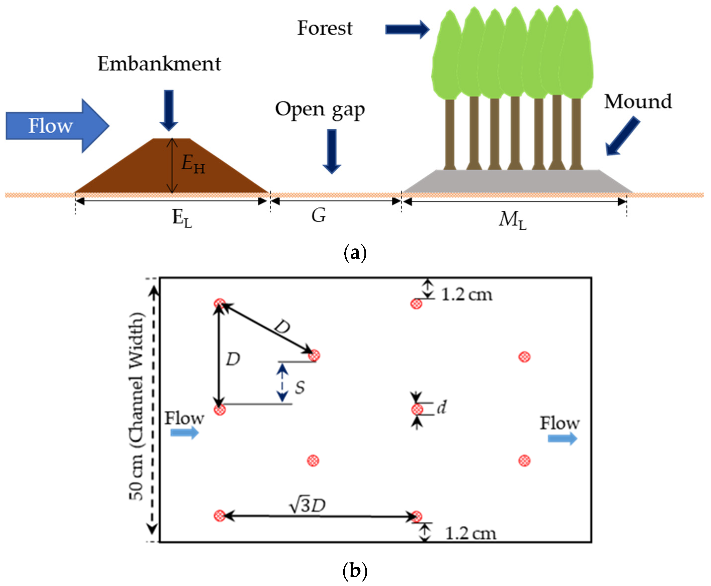
Figure 1. (a) Schematic of a compound tsunami mitigation structure; (b) arrangement of the forest where the red circles represent the individual trees.
Geosciences 15 00243 g001
Figure 2. Schematic of the hydraulic jump type; (a) Type N, (b) Type Nappe, (c) Type A Jump and (d) Type B Jump; where Type N means no jump.
Geosciences 15 00243 g002
Figure 3. Flow structures in the EM (without forest) for (a) MH = 0.12, (b) MH = 0.19, (c) MH = 0.25, and (d) MH = 0.37.
Geosciences 15 00243 g003
Figure 4. Flow structures in the EMF: (a) Case-EMFR4, (b) Case-EMFR7, (c) Case-EMFR12.
Geosciences 15 00243 g004
Figure 5. Pictures Flow structures in the experimental flume; (a) Case-EML3, (b) Case-EML3, (c) Case-EML3, (d) Case-EMFR4, (e) Case-EMFR7, (f) Case-EMFR7, (g) Case-EMFR12, (h) Case-EMFR12.
Geosciences 15 00243 g005
Figure 6. Average water depths in the water cushion: (a) MH = 0.12, (b) MH = 0.19, and (c) MH = 0.25.
Geosciences 15 00243 g006
Figure 7. Percentage of energy reduction through the mitigation system: (a) MH = 0.12, (b) MH = 0.19, and (c) MH = 0.25.
Geosciences 15 00243 g007
Table 1. Experimental cases.
CasehcMH (cm)ML (cm)No. of Tree Row on MoundS/d
EML10.1, 0.16, 0.20, 0.26, 0.34, 0.441.8, 2.7, 3.6, 5.49.5-------
EML20.1, 0.16, 0.20, 0.26, 0.34, 0.441.8, 2.7, 3.6, 5.416-------
EML30.1, 0.16, 0.20, 0.26, 0.34, 0.441.8, 2.7, 3.6, 5.427-------
EMFR40.1, 0.16, 0.20, 0.26, 0.34, 0.441.8, 2.7, 3.69.542.5
EMFR70.1, 0.16, 0.20, 0.26, 0.34, 0.441.8, 2.7, 3.61672.5
EMFR120.1, 0.16, 0.20, 0.26, 0.34, 0.441.8, 2.7, 3.627122.5
Note: The suffixes L1, L2, and L3 stand for mound lengths of 9.5, 16, and 27 cm, respectively; R4, R7, and R12 represent the number of rows of trees in the forest model over the mound as 4, 7, and 12, respectively.
Disclaimer/Publisher’s Note: The statements, opinions and data contained in all publications are solely those of the individual author(s) and contributor(s) and not of MDPI and/or the editor(s). MDPI and/or the editor(s) disclaim responsibility for any injury to people or property resulting from any ideas, methods, instructions or products referred to in the content.