Review

Induced Partial Saturation: From Mechanical Principles to Engineering Design of an Innovative and Eco-Friendly Countermeasure against Earthquake-Induced Soil Liquefaction

by
Lucia Mele
1,*,
Stefania Lirer
2 and
Alessandro Flora
1
1
Department of Civil, Architectural and Environmental Engineering, University of Napoli Federico II, 80125 Napoli, Italy
2
Department of Engineering of Sustainability, University of Roma Guglielmo Marconi, 00193 Roma, Italy
*
Author to whom correspondence should be addressed.
Geosciences 2024, 14(6), 140; https://doi.org/10.3390/geosciences14060140
Submission received: 10 April 2024 / Revised: 17 May 2024 / Accepted: 20 May 2024 / Published: 23 May 2024
(This article belongs to the Special Issue Earthquake-Induced Soil Liquefaction: From Small to Large Scale)

Abstract

:
Earthquake-induced soil liquefaction is a catastrophic phenomenon that can damage existing building foundations and other structures, resulting in significant economic losses. Traditional mitigation techniques against liquefaction present critical aspects, such as high construction costs, impact on surrounding infrastructure and effects on the surrounding environment. Therefore, research is ongoing in order to develop new approaches and technologies suitable to mitigate liquefaction risk. Among the innovative countermeasures against liquefaction, Induced Partial Saturation (IPS) is considered one of the most promising technologies. It consists of introducing gas/air bubbles into the pore water of sandy soils in order to increase the compressibility of the fluid phase and then enhance liquefaction resistance. IPS is economical, eco-friendly and suitable for urbanised areas, where the need to reduce the risk of liquefaction must be addressed, taking into account the integrity of existing buildings. However, IPS is still far from being a routine technology since more aspects should be better understood. The main aim of this review is to raise some important questions and encourage further research and discussions on this topic. The review first analyses and discusses the effects of air/gas bubbles on the cyclic behaviour of sandy soils, focusing on the soil volume element scale and then extending the considerations to the real scale. The use of useful design charts is also described. Moreover, a section will be devoted to the effect of IPS under shallow foundations. The readers will fully understand the research trend of IPS liquefaction mitigation and will be encouraged to further explore new practical aspects to overcome the application difficulties and contribute to spreading the use of this technology.

1. Introduction

The term soil liquefaction can be elucidated as the transformation of saturated granular soils from a solid to a liquid phase due to the consequences of excess pore water pressure increases during earthquakes or other forms of rapid loading, resulting in a concurrent decrease in soil’s effective stresses. The loss of contact between soil particles and then a fluid-like behaviour of soils [1,2,3] causes severe damage in operational facilities and natural ecosystems, with considerable economic and human losses.
The calamity of liquefaction can be reduced by adopting a suitable ground improvement technique to increase the liquefaction resistance of potentially liquefiable soils.
Several techniques to mitigate liquefaction risk have been proposed and used for many decades, but each of them presents critical aspects, such as high construction costs, impacts on surrounding infrastructure or effects on the surrounding environment. Sharma et al. [4] discussed widely the advantages and problems associated with traditional countermeasures against liquefaction. For example, soil densification—through dynamic compaction, vibro-floatation, sand compaction piles, blasting and compaction grouting—is generally energy-intensive and has a great impact on surrounding infrastructures. Moreover, especially for dynamic compaction, the method is applicable to shallow layers (up to 10 m from the ground surface) [4]. Soil replacement, which consists of adjusting the grain size distribution of soil prone to liquefaction through the excavation and removal of liquefaction susceptible soils, is generally not suitable for large construction sites, and the transportation costs may be high. Conventional grouting requires cement and chemical grouts, which are environmentally unfriendly. Some grouts can show poisoning effects and contaminate soil and groundwater [5]. Drainage systems promote the dissipation of excess pore water pressure but plugging of drains causes a reduction in their effectiveness over the years. Moreover, they do not eliminate settlements due to shaking. Similarly to drainage systems, the decrease in the degree of saturation of soil susceptible to liquefaction can decrease the quick dissipation of excess pore water pressure. The decrease in the degree of saturation can be achieved by lowering the groundwater table (dewatering), but the pumping must be maintained continuously. It makes the method difficult to apply and expensive. However, the degree of saturation of liquefiable soils can also be reduced by introducing air/gas bubbles into the pore water phase, thus inducing partial saturation.
Unlike conventional techniques, the decrease in the degree of saturation of liquefiable soils through the introduction of air/gas bubbles into pore water—called the Induced Partial Saturation (IPS) technique—does not seem to present critical issues linked to high costs, environmental aspects or impact on surrounding infrastructure. Sharma et al. [4] indicated possible problems as the “applications difficulties”. Although the in situ application of this technology poses various challenges, these drawbacks can be overcome through research, which is rapidly evolving in this topic. Since the advantages seem to prevail over the associated problems, IPS is considered one of the most innovative and promising techniques to mitigate liquefaction risk. This review offers an overview of IPS, raising some important questions and discussions about the main challenges of this technique. Researchers will fully understand the research trend in order to explore new aspects of IPS and simplify its in situ applications.

2. Degree of Saturation in Sandy Soil Deposits

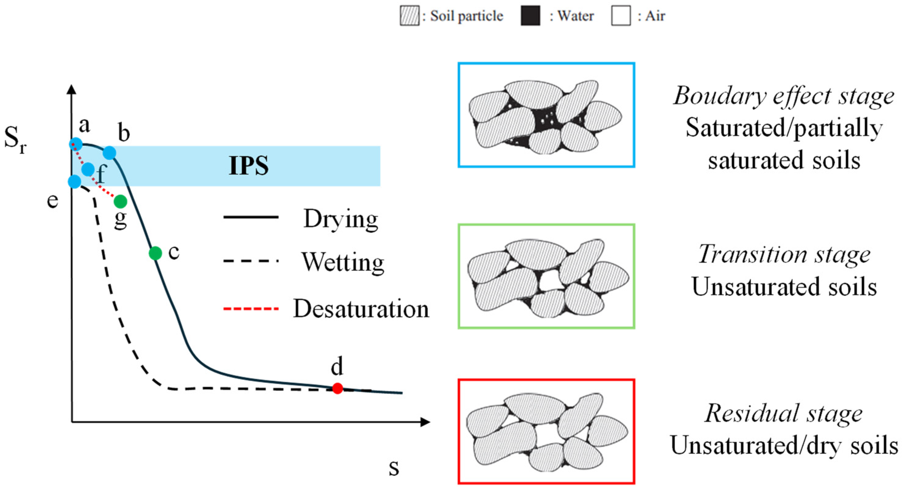
In natural deposits, the state of saturation differs according to the configuration of air distribution in soils, as can be seen in Figure 1a (from [6]).
The soil layers well above the current groundwater level are generally unsaturated, where pores are filled with air and water meniscus, and pore water pressures are negative. The continuous air phase is prevalent, and large matric suction, defined as the difference between the pore air and pore water pressures, is present due to the surface tension at the pore air and pore water interfaces. The surface tension tends to interact with soil structures, and this affects the mobilisation of shear strength [7]. In this case, Terzaghi’s principle does not hold, and more complex expressions should be used [7,8]. In response to the increase in confining stress, the matric suction gradually reduces. The soil layers well below the groundwater level are often fully saturated, where all interparticle pores are completely filled with water, and pore water pressures are positive relative to atmospheric pressure. Additionally, the soil layers below the groundwater level can be in a partially saturated state with entrapped air bubbles, which can occur naturally (e.g., biological activities [9]; pore fluid pressure drop or generally fluctuating water table) or artificially (e.g., air injection). Partially saturated or quasi-saturated soils have lower degrees of saturation (Sr) than saturated soils due to the existence of air bubbles trapped within the pore fluid. The diameters of the bubbles are generally smaller than or the same size as the soil particles. In such conditions, surface tension is generally ignored [10]. It is assumed that the bubbles in discrete forms fit into the void spaces without interacting with the soil structure; in other words, Terzaghi’s principle still holds because suction has no mechanical effects on the soil skeleton. The validity of Terzaghi’s effective stress principle was also demonstrated experimentally by Finno et al. [11].
As reported by Kohogo et al. [12], these three systems (unsaturated, partially and fully saturated) in soils can be distinguished by the air entry value (AEV) and residual matric suction value in the Soil Water Retention Curve (SWRC), which describes the relationship between suction and saturation degree. As reported by Fredlund [13], the SWRC can be divided into three stages: the boundary effect stage, the transition stage and the residual stage (Figure 1b).
In the boundary effect stage, pore air only exits as air bubbles surrounded by water (partially saturated soils). Suction is lower than the air entry value, recognized as the suction state where the entrance of air into the largest soil pore is first permitted during the desaturation of saturated soil [14]. This stage is also known as the insular air saturation condition.
In the residual stage, menisci formed around grain contact points are relevant. This stage is also known as the pendular saturation condition.
In the transition stage, there is an intermediate condition between the above stages. This stage is also known as the fuzzy saturation condition.
However, it is important to highlight that SWRCs present hysteretic behaviour. In other words, drying and wetting curves are different due to the “ink-bottle” and “rain-drop” (contact angle difference) effects during the drying and wetting processes [15]. Indeed, a fully saturated sand (a) can follow two different desaturation paths (Figure 2). In a drying path, the soil is allowed to drain under increasing suction from (a) to (b) and (c), continuing to a residual water content at point (d). Desaturation can also follow path (a) to (f), where discrete air bubbles are introduced with zero suction and can eventually grow and move towards point (g), although the shape of this path is not known. In the wetting path, water can be introduced to the soil starting from any point on the drying path (e.g., point d), leading to point (e) with occluded air bubbles [16].
It means that in Induced Partial Saturation (IPS), the desaturation path (red dashed line in Figure 2) is generally followed. Therefore, degrees of saturation lower than Sr in correspondence with the AEV (point b in Figure 2) can be reached while maintaining quasi-saturated conditions (occluded air/gas bubbles). Among others, Grozic et al. [17] and Zeybek and Madabhushi [6] indicated Sr = 80% as the threshold value between unsaturated and partially saturated conditions.

3. Equivalent Compressibility and Effects of Air/Gas Bubbles on Cyclic Behaviour of Sands

The presence of gas/air bubbles in the pore water of soil can significantly modify the bulk modulus of the pore fluid.
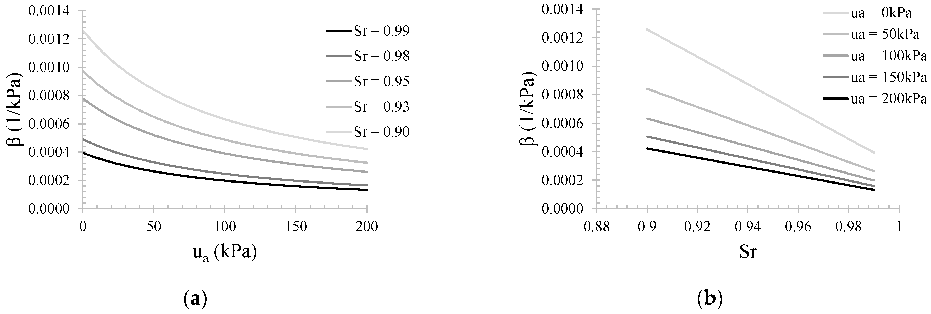
When air/gas is in the form of occluded bubbles, the gas bubbles and pore water behave like a homogeneous compressible fluid, and the surface tension effect becomes inconsiderable. Several relationships have been introduced in the literature to evaluate the compressibility of the fluid phase [18,19,20,21,22,23,24,25,26]. However, the most used relationship is one proposed by Fredlund [19]. Fredlund [19], using the classic concepts of mass conservation and Boyle’s and Henry’s laws to define the compressibility of miscible gas–fluid mixtures in the pore fluid phase of partially saturated soils, proposed the following equation for pore fluid compressibility to simulate the presence of air bubbles in the pore water:
β = S r · β w + 1 S r u a + P a + h · S r u a + P a ,
where Sr is the degree of saturation, βw is the water compressibility (4 × 10⁻⁷ 1/kPa), h is the volumetric coefficient of solubility (generally assumed 0.03 for air), ua is the air pressure, and Pa is the atmospheric pressure (101 kPa).
Equation (1) introduces the three sources that contribute to the compressibility of gas–liquid mixtures. The first term is related to the compressibility of pore liquid. The second term is related to the compression of pore gas, which, according to Boyle’s law, is proportional to the absolute pore gas pressure (i.e., the term ua + Pa). The last term is related to the dissolution of gas, which is controlled by Henry’s law and the coefficient of solubility h.
In Figure 3, β has been plotted with pore air (relative) pressure and degree of saturation. It can be noted that for higher values of ua, the compressibility of fluid phase tends to get constant, while a linear trend is observed for the relationship Sr–β.
Equation (1) takes into account the nature of the gas through the term h. Indeed, different gases present different solubility in water (h is 0.032 for O2, 0.04 for CH4, 0.15 for N2 and 0.83 for CO2 at T = 20 °C). The solubility of gas in water is ruled by Henry’s law. It states that the gas pressure Pg (partial pressure when a single gas species is taken into account) is directly proportional to the concentration of the gas in the water phase Ca through Henry’s constant KH, according to the following equation:
P g = K H · C a .
It should be mentioned that the volumetric coefficient of solubility (h; Equation (1)) is linked to KH according to the following relationship:
h = 1 K H · R · T ,
where R is the ideal gas constant (0.0821 l·atm/(mol·K)), and T is the temperature in Kelvin. As reported by Fredlund [19], the rate at which air dissolves into water is described by Fick’s Law of diffusion, where the driving force is a concentration or density difference between the free air and the air in the ‘cages’ in the water.
In Figure 4, the effect of h on Equation (1) is showed. Carbon dioxide (CO2) exhibits higher compressibility due to its higher solubility in water. Moreover, β seems to be roughly constant with Sr. On the contrary, for lower value of h, β decreases faster with Sr.
Equation (1) implies that partially saturated sands can change the volume under undrained conditions due to the finite compressibility of pore fluid. The increments of volumetric strain (dεv) can be computed as follows:
d ε v = d u · β · n ,
where du is the increment of pore pressure, and n is the porosity of the soil.
Okamura and Soga [27], applying Boyle’s law, computed the maximum volumetric strain of the soil when the effective stresses become zero (i.e., ua = uw = σ), neglecting all possible effects of air dissolution into water. The maximum volumetric strain is called potential volumetric strainv*).
ε v * = e 0 1 + e 0 · 1 S r 0 · 1 u a , 0 σ ,
where e0, Sr0 and ua,0 are the initial void ratio, degree of saturation and pore air pressure, respectively, and σ is the total stress. As expected, Equation (5) indicates that εv* increases when Sr decreases. During earthquakes, the increase in pore water pressure leads to the compression of air bubbles and then an increase in the volumetric strains of soils. In other words, the degree of saturation changes. However, it should be specified that the attainment of the potential volumetric strain does not necessarily correspond to a full saturation condition (Sr = 100%) of soils. In Figure 5, the results of cyclic triaxial tests on partially saturated specimens have been plotted in terms of degree of saturation with the applied number of constant amplitude stress cycles (Ncyc) [28].

4. Laboratory Tests on Partially Saturated Sandy Soils

To explore the effect of air/gas bubbles on the liquefaction behaviour of sands, laboratory tests are generally performed. Since they reproduce in situ soil conditions and control the variables that play an important role in soil behaviour, they allow us to better understand the mechanisms in soils under particular conditions (i.e., liquefaction).
Generally, cyclic triaxial or simple shear tests are performed to investigate the liquefaction strength or the accumulation of excess pore water pressure during undrained cyclic phase [27,29,30,31,32,33,34]. Shaking table [35,36,37,38,39] or centrifuge [40,41,42,43,44] tests should be preferred when interactions with structures (i.e., shallow foundation and, pipelines) are considered.

4.1. Preparation of Partially Saturated Specimens

One of the challenges in the study of liquefaction behaviour of partially saturated soils is the preparation of specimens. Bao et al. [45] summarized the main techniques into four categories: air injection, biogas produced by bacteria in the soil, electrolysis, sand compaction pile and chemical methods.
Air injection is mainly suitable for shaking table or centrifuge tests rather than cyclic triaxial or simple shear tests. It consists of injecting pressurized air into the pore water of saturated soils. Generally, air injectors are used at the base of the model. As reported by Marasini and Okamura [41], special attention must be given to the air injection pressure so that soil grains are not disturbed by the airflow. Ogata and Okamura [46] suggested that the injection pressure should not overcome Pinj,max, calculated as follows:
P i n j , m a x = P h y d + 0.5 · σ c
where Phyd is the hydrostatic pressure, and σ’c is the effective vertical stress at the depth of the air injector.
However, air injection pressure should be higher than Pinj,min, defined as follows:
P i n j , m i n = P h y d + A E V
where AEV is the air-entry value as defined in §2.
Zeybek and Madabhushi [42] suggested gradually increasing air injection pressure under existing buildings to avoid unacceptable settlements during the injection process. It is worth noting that the desaturation of soils beneath existing foundations requires a well-controlled air injection process and close monitoring of foundation response.
Zeybek and Madabhushi [43] performed several centrifuge tests to study the liquefaction response of air-injected partially saturated soils beneath shallow foundations. The model layout is reported in Figure 6a. Air was injected at the base of the model. Through 2D digital images captured on the side of saturated (Figure 6b) and partially saturated (Figure 6c) soils, Zeybek and Madabhushi [43] investigated the uniformity of air distribution in centrifuge tests. The images illustrate how the colour of soils tended to change with the injection of air. It is observed that the colour of the soil was much lighter in the portion of soils with air bubbles. The shape of the effective partially saturated zone, indicated by the broken curves, was an almost parabolic U, and it was approximately symmetrical. It, however, appears that the air bubbles were retained erratically, and the partial saturation was not completely uniform, even within the effective partially saturated zone. Indeed, pore fluid softening through gas injection is limited by the percolation of air bubbles along preferential paths formed by interconnected large pore throats, thus failing to create a homogeneous distribution of small bubbles.
It should be mentioned that during injection, air tends to float up and escape into the atmosphere; only a part of the air remains within the pores of the soil. The volume of air in the soil can be estimated by observing the increase in residual water level.
Another innovative technique to induce partial saturation in soil is the metabolic activity of bacteria, which generate biogas. Gas produced by microorganisms can reduce the degree of saturation to 80–95%. Gas production tends to mimic bacteria population growth rates and, therefore, can be controlled by limiting bacterial activity through nutrient availability and environmental conditions such as temperature, among other factors [47].
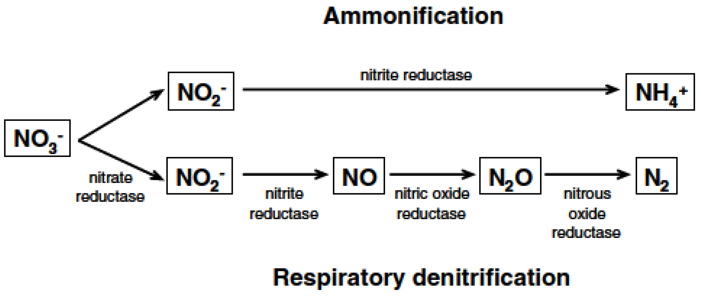
As reported by Rebata-Landa and Santamarina [48], the most common biogenic gases found in near-surface soils are CO2, H2, CH4, and N2. Carbon dioxide (CO2) has high solubility in water, causing short residency time; methane (CH4) is a greenhouse gas, and both methane and hydrogen (H2) are combustible. By contrast, nitrogen gas (N2) presents several advantages within the scope of this investigation: it is neither explosive nor a greenhouse gas, and its solubility in water is very low (§ 2), so less gas is needed to produce bubbles, and the bubbles will remain undissolved for longer periods of time. According to Rebata-Landa and Santamarina [48], nitrate can be reduced in the environment through the direct path of ammonification, in which the product is ammonia, or it can take the indirect path of respiratory denitrification, in which case the products may be nitric oxide, nitrous oxide, and nitrogen gas; the two paths are shown in Figure 7.
Electron donors (generally organic compounds) are used to trigger the denitrification process. He et al. [49,50] suggested using methanol (CH3OH), ethanol (C2H5OH) or sodium acetate (CH3COONa). The reactions are as follows:
5 C H 3 O H + 6 N O 3 3 N 2 + 5 C O 2 + 7 H 2 O + 6 O H ,
and
5 C 2 H 5 O H + 12 N O 3 6 N 2 + 10 C O 2 + 9 H 2 O + 12 O H ,
5 C H 3 C O O + 8 N O 3 4 N 2 + 10 C O 2 + H 2 O + 13 O H .
Wang et al. [51] proposed to use glucose (C6H12O6) as an electron donor, with the reaction given as follows:
5 C 6 H 12 O 6 + 24 N O 3 12 N 2 + 30 C O 2 + 18 H 2 O + 24 O H .
However, regardless of the electron donors and the subsequent reactions triggered, treatment using biogas can make smaller and more evenly distributed gas bubbles in pore water, which are less likely to escape from the soil [45] compared to air injection methods.
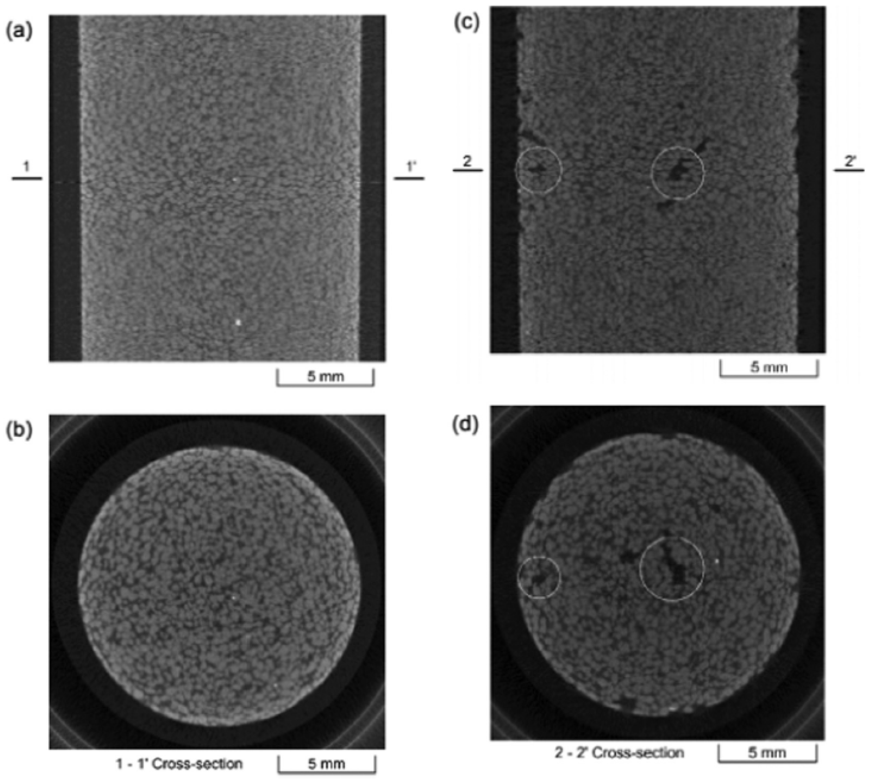
He et al. [49] used computer tomography (CT) to observe microbially desaturated soil samples. In Figure 8a,b, the sample is saturated, and the distributions of sand grains and pore voids are uniform. In Figure 8c,d, the sample is desaturated to a saturation degree of 94%. Pockets of pores, shown as dark patches in the images, are slightly larger than the size of a sand grain (the mean size of the sand grains is 0.4 mm). The dark colour of the pockets indicates that the pockets consist of gases or a combination of gases and water. However, the uniformity of bubbles in a microbial-desaturated sand column seems to be good. This method has been used to desaturate specimens for cyclic triaxial tests [50,51], cyclic simple shear [52,53] or shaking table tests [36,39].
Another method to generate oxygen and hydrogen gases in sand using water electrolysis was developed by Yegian et al. [54]. Practically, electrolysis consists of the ionization of hydrogen and oxygen gases when an electrical current is passed through water using electrodes. As reported by Yegian et al. [54], electrolysis was selected as an efficient application to induce partial saturation since it introduces gas into the soil pores without the application of any pressure. Oxygen and hydrogen are produced through water electrolysis at the anode and cathode, respectively, following the ensuing chemical reactions:
4 H 2 O + 4 e 4 O H + 2 H 2 c a t h o d e
and
2 H 2 O 4 e 4 H + + O 2 a n o d e .
It is conceptually important to underline that since H2 is produced during the electrolysis process, its quantities must be lower than critical quantities because hydrogen is considered the most unstable gas with respect to safety explosion hazards. Thus, gases produced via electrolysis should be sufficient to ensure the target increment in liquefaction resistance and, concurrently, they must be lower than specific quantities with respect to safety hazard issues.
Desaturation through electrolysis has been used in shaking table tests [54]. Among several techniques, this one results in a probably high-cost application, and as pointed out by Eseller-Bayat et al. [37], the current application leads to a non-uniform distribution of gas bubbles within sand specimens.
An alternative approach to achieving partially saturated conditions lies in the employment of chemical compounds able to generate gas bubbles. To this aim, Eseller-Bayat et al. [37] proposed to use sodium perborate monohydrate (NaBO3∙H2O). This chemical compound, also known as PBS-1, is able to generate oxygen through the following chemical reaction with water:
2 N a B O 3 · H 2 O + 2 H 2 O 2 H 2 O 2 + 2 B O 3 3 + 2 N a + + 4 H +
and
2 H 2 O 2 2 H 2 + O 2 .
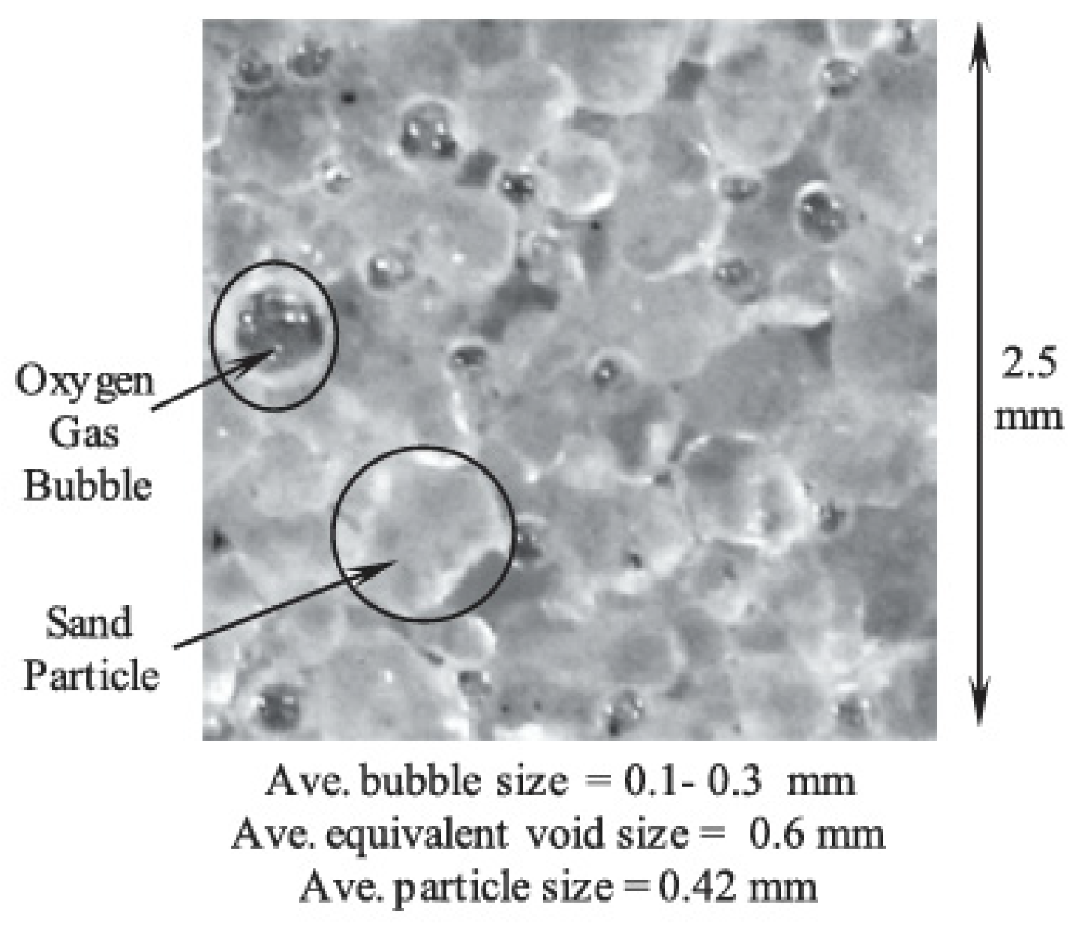
From a chemical point of view, sodium perborate monohydrate reacts with water and generates hydrogen peroxide (H2O2), which is a ready source of oxygen gas. Hence, through the chemical reaction reported in Equation (15), O2 gas is formed, and partially saturated conditions can be achieved. Operatively, Eseller-Bayat et al. [37] carried out wet pluviation of dry sand + PBS-1 to set up partially saturated samples. After preparation, a high-resolution camera was used to assess the uniformity of the desaturation process. As shown in Figure 9, the use of sodium perborate monohydrates ensures a good distribution—in terms of uniformity—of the oxygen-generated bubbles. Moreover, it can be used to achieve degrees of saturation lower than 80%.
Recently, Zeybek [55] proposed using a denture cleanser to desaturate soil in a 1-g shaking table. It can easily dissolve in water and produces a significant amount of oxygen bubbles at the end of the chemical reaction. Further studies are needed.
Among the desaturation methods described above, it should be mentioned that in soil element tests, partially saturated specimens can also be achieved through flushing [31,34] or by imposing different values of back pressure to have different Sr [32,56]. Moreover, Vega-Posada et al. [57] developed a procedure that consists of replacing pore fluid in a saturated specimen with CO2-saturated water. Thereafter, the back pressure in the specimen was gradually decreased while the applied p0 was kept constant, thus forcing CO2 to come out of the solution in the form of occluded bubbles. This procedure has also been used by Finno et al. [11].

4.2. Estimation of the Degree of Saturation

To assess the degree of saturation of specimens in element testing (i.e., triaxial tests), the B-test can be performed.
This measurement, carried out under undrained conditions, represents an integral response of the specimen under the increment of the total stresses in radially symmetric conditions and can be experimentally found as B = Δu/Δσ easily. On the other hand, the B-value can be theoretically expressed as follows [58]:
B = 1 1 + n · K b K f ,
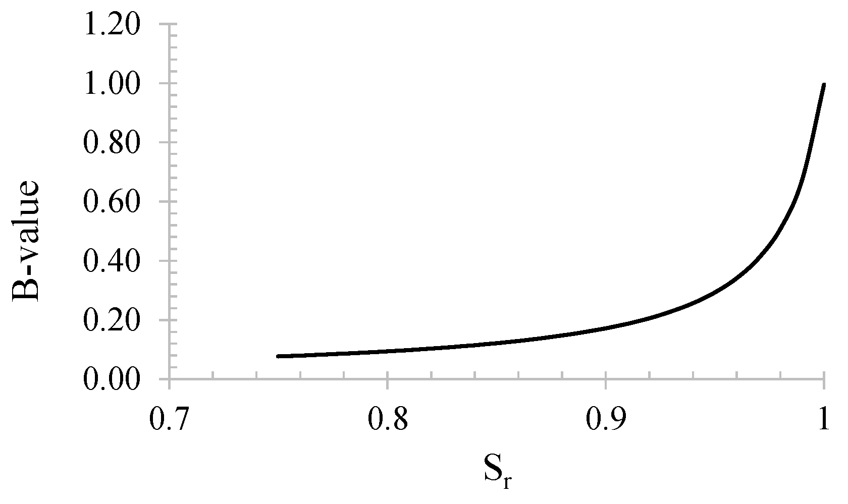
where n is the porosity, Kb is the bulk modulus of the soil skeleton, and Kf is the bulk modulus of the pore fluid. In partially saturated specimens, the equivalent bulk modulus of the pore fluid, Kf, is given using 1/β (Equation (1)). With such a basis, by neglecting the solubility of air/gas in water (h = 0, in Equation (1)), B can be linked to the degree of saturation [59]:
B = 1 1 + n · K b K w + n · K b u a + P a · 1 S r .
As an example, the relationship between Sr and B is reported in Figure 10. It can be noted that for higher Sr, B-value sharply increases.
Astuto et al. [60] proposed Equation (17) to estimate Sr from B-value:
S r = B · 1 + n · K b · 1 K w + 1 u a + P a 1 B · n · K b · u a + P a .
Many authors have used a simplified theoretical relationship based on the P-wave velocity linked with the biphase nature of the pore fluid and the B-value [61]:
V p = 4 3 · G 0 + K b , 0 1 B 1 n · ρ s + n · ρ f 1 2 ,
where (1 − ns + nρf is the total density of the soil, and G0 is the maximum shear modulus. Hence, since the equation relates Vp with B-value, and the latter is connected to Sr in turn, a direct link could be derived between Vp and Sr.
Therefore, a direct link between Vp and Sr is obtained by substituting Equation (16) into Equation (18). Note that both equations include the bulk modulus of the soil skeleton, denoted as Kb and Kb,0 for Equations (16) and (18), respectively. The above is because B-tests are related to a higher strain level than that referred to in bender element tests.
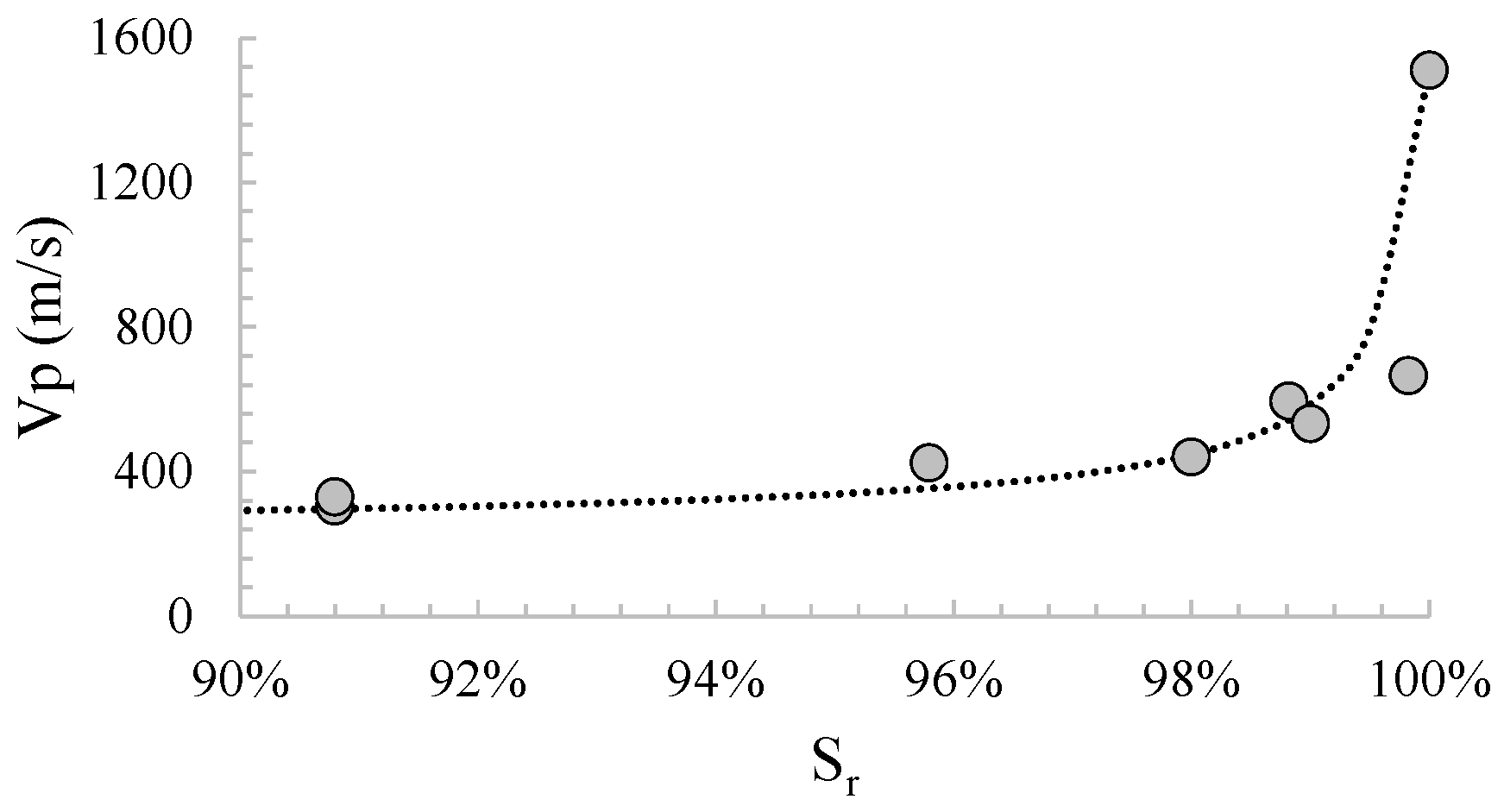
As an example, the relationship between Sr and P-wave velocity is reported in Figure 11 [62]. As known, when Vp is higher than 1500 m/s, the soil can be considered saturated.
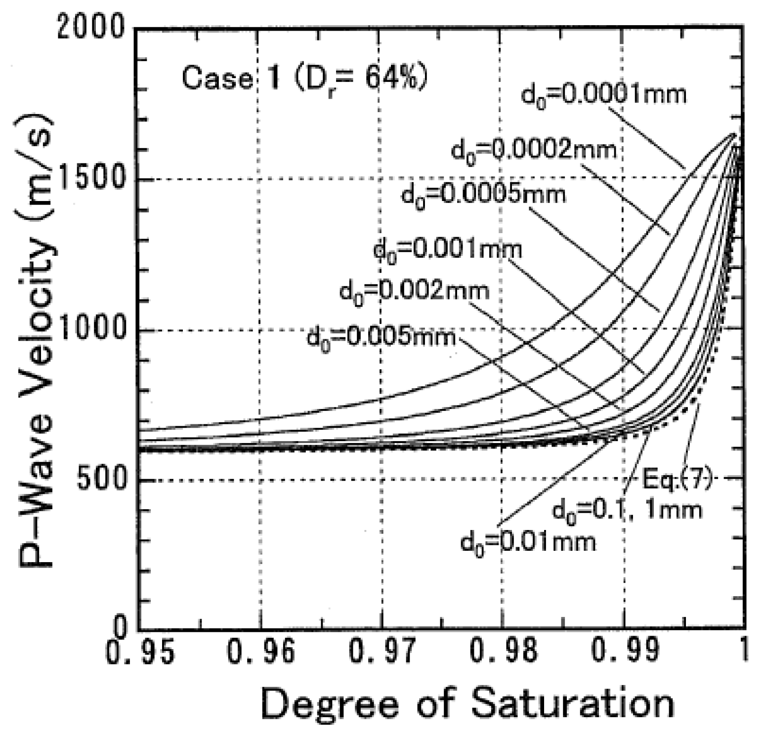
However, it has been reported that the non-uniform distribution of pore water, the size of air bubbles and their distribution within the soil specimens affect Vp significantly [63,64]. In Figure 12, the effect of bubble diameter on the relationship Sr–Vp is plotted. The P-wave velocity increases with a decrease in the air bubble size. This tendency is significant when the air bubble size is less than about 0.005 mm. It means that the relationship between Vp and Sr should be used with care.

4.3. Liquefaction Resistance of Partially Saturated Sands

The Induced Partial Saturation (IPS) technique consists of introducing occluded air/gas bubbles into the continuous water phase of sandy soils. Despite a small reduction in Sr (typically higher than 80%), laboratory tests have demonstrated that liquefaction resistance largely increases (e.g., [27,29,31,32,33,34,36,37,54,65,66,67,68,69,70,71]). This is due to the higher compressibility of the fluid phase of partially saturated sands compared to saturated ones. Indeed, the occluded air/gas bubbles play a role in absorbing generated excess pore pressures by reducing their volume [27]. These air/gas bubbles work like a damper, decreasing the earthquake-induced pore water pressure build-up, delaying the attainment of liquefaction, and consequently increasing soil liquefaction resistance.
In laboratory settings, results are usually interpreted in the Ncyc vs. CSR plane, where Ncyc represents the number of constant amplitude stress cycles applied, and CSR the Cyclic Stress Ratio is defined in cyclic triaxial tests as follows:
C S R = q d 2 · σ c ,
where qd is the cyclic deviatoric stress, and σ’c is the effective confining stress.
Nliq is the value of Ncyc needed to reach liquefaction for a given value of CSR. For N = Nliq, the applied cyclic stress ratio represents the Cyclic Resistance Ratio CRR. The locus (Nliq:CRR) identifies the Cyclic Resistance Curve. Conventionally, it is assumed that liquefaction in saturated soils is triggered at 5% double axial strain amplitude for cyclic triaxial tests and 7.5% double shear strain amplitude for cyclic simple shear tests (strain criterion), or at ru = 0.90, where ru the pore pressure ratio (=∆u/σ’c) (stress criterion), with Δu being the excess of pore water pressure and σ’c the effective confining stress. Wu et al. [72], Lirer and Mele [1], and Mele [2] demonstrated that for saturated loose sands, strain and stress criteria generally exhibit the same number of cycles to liquefaction. On the contrary, for Sr lower than 100%, the two criteria demonstrate different results, as shown by Mele et al. [73]. Mele et al. [73] reported the difference between the number of cycles at liquefaction of non-saturated sands achieved with strain and stress criteria versus Sr for cyclic triaxial tests (Figure 13).
According to Mele et al. [73], the discrepancy between stress and strain criteria in terms of Nliq in non-saturated sands could be due to the fact that in undrained cyclic tests on fully saturated sand, the development of axial strains corresponds to the development of shear strains γ, without causing any development of volumetric strains. It means that εa is responsible for the generation of pore pressure, and a direct correspondence between Nliq evaluated with stress and strain criteria exists. On the contrary, in non-saturated sandy soils, εa contributes to the development of shear strain γ as well as volumetric strain εv. The latter, due to a higher compressibility of the fluid phase, is responsible for decreasing excess pore pressure build-up. It means that a direct correspondence between the two triggering criteria does not exist. Moreover, the difference tends to become important when the degree of saturation decreases; as a matter of fact, volumetric strains increase, and therefore, excess pore pressure build-up decreases. Although within the range of Sr between 80 and 99%, the difference in the number of cycles to liquefaction between stress and strain criteria never exceeds 5 (Figure 13b); it is important to introduce a unique and correct criterion to identify liquefaction in non-saturated sands, avoiding the misprediction of liquefaction resistance for this kind of soils. Mele et al. [73] used apparent viscosity to correctly identify the liquefaction triggering. Apparent viscosity, as defined by Chen et al. [74], is a physically based parameter able to capture the state change from solid to liquid that occurs when liquefaction is attained. The viscous approach confirms the strain criterion. Therefore, the strain criterion (εDA = 5% in cyclic triaxial tests) should be preferred in partially saturated sandy soils to identify liquefaction triggering. Further details may be found in Mele et al. [73]. Hereafter, liquefaction in non-saturated sands will be identified in terms of strains.
In Figure 14, some liquefaction resistance curves of partially saturated sands are plotted together with those of saturated soils. As expected, when the degree of saturation decreases, liquefaction resistance curves move upwards, so liquefaction resistance increases.
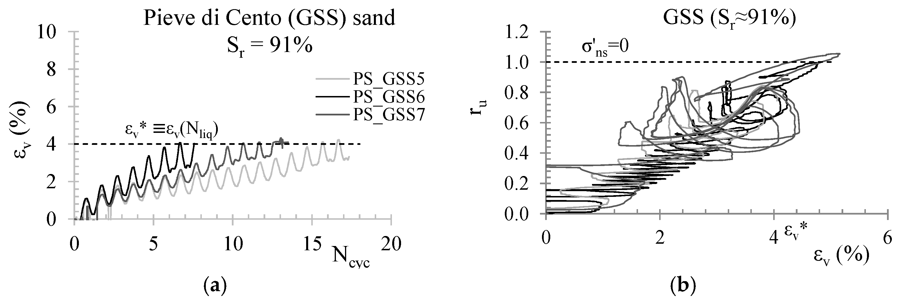
As mentioned above, the improvement of liquefaction resistance of partially saturated sands compared to that of saturated soils is due to the higher compressibility of the fluid phase. Indeed, partially saturated soils in the undrained cyclic stage exhibit volumetric strains. Mele et al. [31] measured the volumetric strains of specimens, and in Figure 15a, εv of three specimens is plotted against Ncyc. The three specimens present the same void ratio (or Dr), effective confining stress (σ’c = 50 kPa), and a similar degree of saturation (Sr ≈ 91%). Although the applied CSR is different, the tests reach a similar final volumetric strain. Moreover, the strong link between the excess pore water pressure build-up and the volumetric strain can be noted in Figure 15b. The curves εv–ru of the three tests overlap, showing, once again, that the relationship is independent of CSR. In both Figures, εv* is the potential volumetric strain defined by Okamura and Soga [27] (Equation (5)).

4.4. Limitations of Cyclic Tests on the Liquefaction Behaviour of Partially Saturated Sands

Soil element testing is extremely useful for studying in depth the liquefaction behaviour of partially saturated sands. However, it should be mentioned that cyclic tests present some issues. The main one is linked to the loading frequency.
When inertial forces are of no interest, the frequency usually adopted in laboratory cyclic tests is usually lower than 0.5 Hz to reduce backlash problems during stress reversal, whereas the highest energy content of real earthquakes is related to higher frequencies (typically 1–10 Hz). In saturated soils, the lower frequency adopted in laboratory tests to analyze liquefaction triggering is of no concern. In contrast, in quasi-saturated soils, frequency may play a role: the increase in pressure within the bubbles during cyclic loading increases gas solubility (in accordance with Henry’s law), and therefore, a gas flow from the gas bubbles to the water is triggered (which is ruled by Fick’s laws), with a subsequent reduction in the volume of the bubbles. The time allowed for such a flow is related to the adopted loading frequency and rules the amount of gas dissolution. The lower the frequency, the higher the amount, and therefore, the higher the volumetric strains. In other words, cyclic tests could exhibit higher compressibility (due to the solubility of air/gas in water) and then higher liquefaction resistance.
Mele et al. [31] compared the theoretical volumetric strain computed with Equation (5) with the measured experimental values (Figure 16a). Especially for higher degrees of saturation, the experimental values of volumetric strains are higher, probably indicating the possible effect of loading frequency. Mele et al. [31] reported the relationship between εv,exp*/εv* and Sr0 (Figure 16b). According to them, to fit the final volumetric strain measured in the laboratory (εv,exp*) at higher values of Sr0, Equation (1) [27] can be modified as follows:
ε v * = e 0 1 + e 0 · 1 S r 0 · 1 u a , 0 σ · f ( S r 0 ;   ω ) ,
where f(Sr0; ω) is a function that theoretically should depend on both the initial degree of saturation and the loading frequency ω. In Mele et al. [31], using a constant frequency (0.1 Hz), only the dependency on Sr0 can be considered. Further work should clarify the role played by frequency loading in cyclic tests. The best fit of the experimental results at such a constant frequency was attained using the following expression of this function:
f . S r 0 = 0.0027 · exp 7.57 · S r 0 .
In conclusion, cyclic tests on partially saturated soils should be used with care because liquefaction resistance could be overestimated.

5. Parameters Ruling the Liquefaction Resistance of Partially Saturated Soils

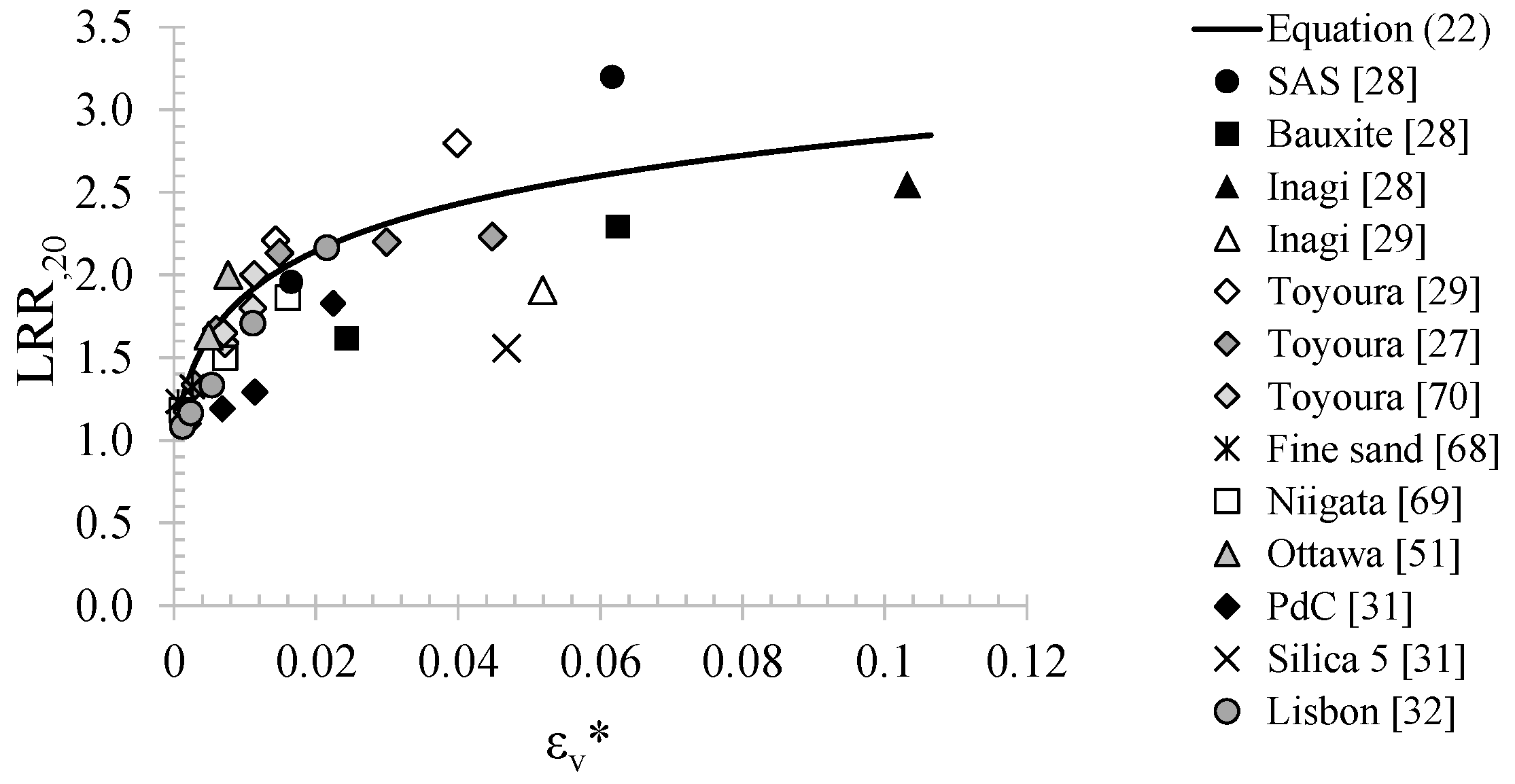
For a long time, researchers have tried to find the parameter(s) ruling the liquefaction resistance of partially saturated sands. Yoshimi et al. [67] identified the degree of saturation (Sr) as the governing parameter in liquefaction of non-saturated soils. Further attempts were made to investigate the role of Skempton’s value (B) for the equivalent fluid [67,75,76], elastic wave velocity [32,33,69,77,78,79] or the volumetric strain ratio (Rv = εv,airv,σ’; where εv,air and εv,σ’ are volumetric strains due to the compressibility of pore air and reduction in confining pressure, respectively) [29]. However, nowadays, one of the simplest and most used parameters is the potential volumetric strain (εv*) [27], already defined in Equation (5). Okamura and Soga [27] linked the liquefaction resistance ratio (LRR,20) to εv*:
L R R 20 = l o g 6500 · ε v * + 10
where LRR,20 is the ratio between the liquefaction resistance of saturated and partially saturated sands (CRRsat and CRRps, respectively) when Nliq = 20.
Wang et al. [29] showed that the theoretical relationship reported in Equation (22) can either overestimate or underestimate the experimental values of LRR,20, as shown in Figure 17.
Mele and Flora [80] proposed volumetric energy to liquefaction (Ev,liq) as a parameter ruling the liquefaction resistance of partially saturated soils. Ev,liq is a synthetic and sound state parameter representing the work required to reduce soil volume, and it can be seen as the sum of three components:
E v , l i q = E v , s k , l i q + E w , l i q + E a i r , l i q ,
where Ev,sk,liq, Ew,liq and Eair,liq represent the specific work conducted to cause the deformation of the soil skeleton, the flow of water and the flow of air into the pore network, respectively. They can be expressed as follows:
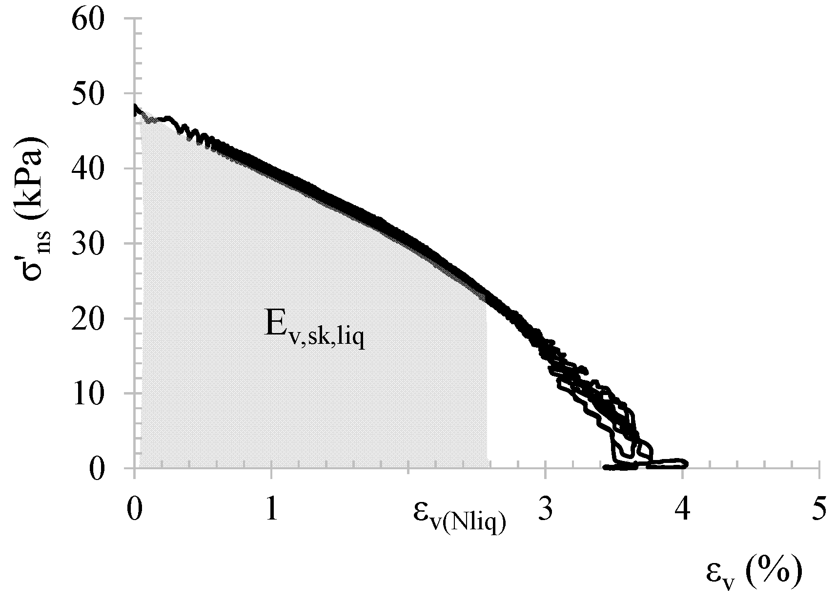
E v , s k , l i q = 0 ε v , ( N l i q ) σ u a + s S r 0 · d ε v ,
E w , l i q = S r 0 S r , l i q e S r 1 + e S r s S r · d S r ,
and
E a i r , l i q = e 0 1 + e 0 1 S r , 0 u a , l i q ln V a i r , 0 V a i r , l i q .
Ev,sk,liq depends on the stress state (σ’ns, where the pedex indicates non-saturated condition), the initial void ratio e0 and the initial degree of saturation (Sr0), while it depends neither on CSR nor on Nliq. Obviously, Ev,sk,liq = 0 for undrained tests on saturated soils. In Equation (24), dεv is the increment in volumetric strain during undrained cyclic loading. Equation (24) represents the area under the average curve of σ‘ns–εv (Figure 18) for a specific soil state and needs knowledge of the stress state at liquefaction σ‘ns,liq (which is not nil in the case in the case of partially saturated soils for which liquefaction is conventionally attained at εDA = 5%) to compute the corresponding extreme of integration εv,(Nliq).
In non-saturated conditions, liquefaction is attained before effective stresses become zero. The value of effective stress at liquefaction will be named in the following as σ’ns,liq. Mele and Flora [80], by applying a best-fitting procedure to experimental data, proposed the following relationship between the ratio σ’ns,liq/σ’ns,0 and the initial degree of saturation (Sr0, expressed in percentage):
σ n s , l i q σ n s , 0 = 2 · 10 4 · S r 0 2 + 2 · 10 2 · S r 0 + 0.10 .
For Sr0 = 100%, Equation (27) gives σ’ns,liq/σ’ns,0 = 0.10, consistent with the definition of liquefaction according to the strain criterion (ru = 0.90). Since Equation (27) was calibrated using data related to values of Sr ≥ 0.5, it is valid only under these conditions and cannot be applied to lower values of Sr.
The energy of the deformation of water (Equation (25)) is due to the changes in water content. Equation (25) can be seen as the energetic contribution of the water content change, where Ew,liq is proportional to the integral of the water retention curve starting from a given initial degree of saturation Sr0.
Finally, the energy of deformation of air (Equation (26)) describes the effect of pressure variation in the gas phase, where Vair,0 is the volume of air at the beginning of the deviatoric phase, while Vair,liq is the volume corresponding to liquefaction condition. Further details regarding the energetic model can be found in [31,80].
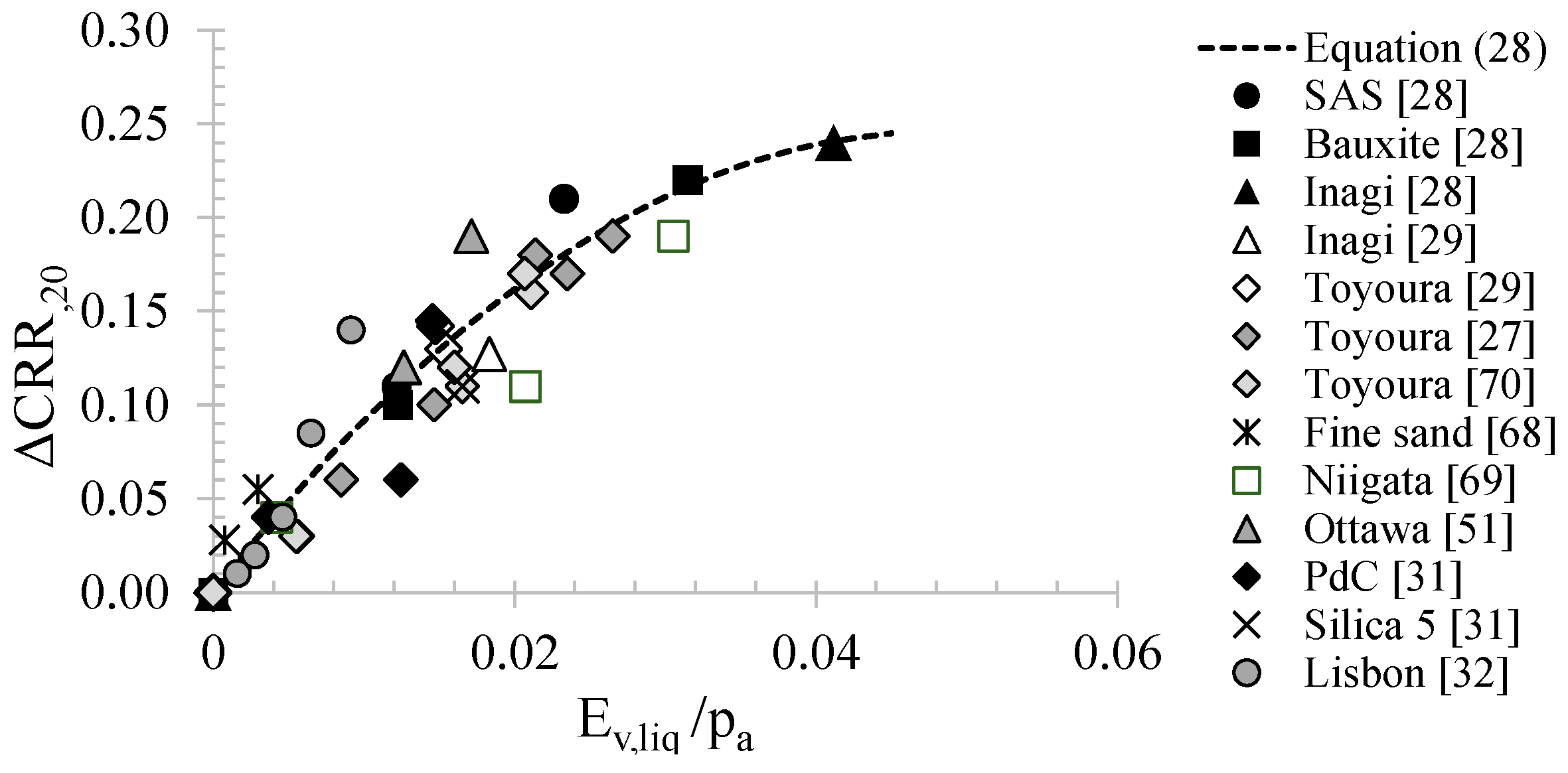
Mele and Flora [80] confirmed the effectiveness of Ev,liq as a parameter ruling the increase in liquefaction resistance from saturated (CRRs) to non-saturated conditions (CRRns) at a given number of equivalent cycles. They proposed the following relationship between Ev,liq and ΔCRR (=CRRns-CRRs):
C R R N l i q = 105.7 × E v , l i q p a 2 + 10.2 × E v , l i q p a .
In Figure 19, the experimental data are published together with Equation (28). It can be noted that the theoretical curve proposed in Equation (28) fits the experimental results better than the proposed relationship based on εv* (Figure 17). It is probably due to the fact that Ev,liq is a complete approach, which also takes into account the work of air flowing into pore networks, a factor neglected by the εv* approach.
Equation (28) allows to predict the non-saturated cyclic resistance, and therefore to plot the non-saturated cyclic resistance curve through a simple upwards translation of the one from saturation conditions, under the simplified hypothesis that the non-saturated and saturated cyclic resistance curves are parallel [29].
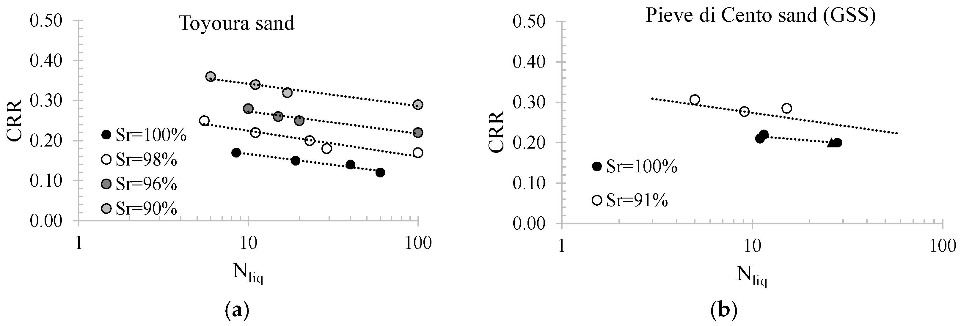
The reliability of the energetic approach to predict liquefaction resistance of partially saturated soils can be confirmed using Figure 20, where some experimental data in the CRR-Nliq plane are compared with simulated liquefaction curves using the energetic approach.

6. IPS: From Small to Large Scale

In this section, the considerations on IPS will be extended to a real scale.

6.1. Desaturation of Soil in Real Scale: Methodologies, Durability and Sr-Monitoring

As reported in Section 4.1, at the laboratory scale, the main methods to achieve desaturated specimens are as follows: air injection, biogas produced by bacteria in the soil, electrolysis and chemical methods. At a large scale, some of these methods are difficult to apply. For example, on a real scale, chemical methods could be difficult due to their very fast reaction with water, resulting in a low applicability of the process itself. On the other hand, electrolysis produces unstable gases with respect to safety explosion hazards. Recently, air injection and biogas produced by bacteria in the soil have been used in several applications.
Moug et al. [81] conducted field trials of microbially induced desaturation in Portland, Oregon, underlain using liquefiable fine-grained soils. Field trials were performed by injecting a substrate solution into the subsurface over a targeted treatment depth interval. Acetate was used as an electron donor. The distribution of the treatment solution and the progress of treatment were monitored using electrical conductivity (EC) measurements as an indicator of fluid salinity. Indeed, the treatment solution had a greater salinity than the native groundwater because microorganisms’ reaction produces either gas, solid minerals or biomass. Therefore, EC is also a direct measure of substrate consumption. Moreover, Vp measurements indicated that Sr was reduced to below 98.5%. In the same site, Soreson et al. [82] monitored the persistence of desaturation for 8 months post-treatment. The results indicated that Sr reduction is persistent over this time. IPS also persisted through seasonal fluctuations of the groundwater table since the end of treatment. This research is still ongoing.
Another methodology to desaturate the soil is air injection. Unlike desaturation with bacteria, which is a new technology, air injection is frequently used and for a long time. It is used in the field of environmental engineering for the treatment of saturated soils and groundwater tables contaminated by volatile organic compounds [83]. This treatment is well known as air sparging.
Thomson and Johnson [84] showed a schematic representation of air distribution during air injection (Figure 21). After a short period of “spherical” growth of the air zone in the vicinity of the injection point, upward growth due to buoyancy will dominate; however, some lateral growth may continue. Once the air zone reaches the water table, the air zone contracts due to increased airflow to the surface. Indeed, when pressurized air is injected into soils, air bubbles tend to rise through the ground surface, driven by buoyancy.
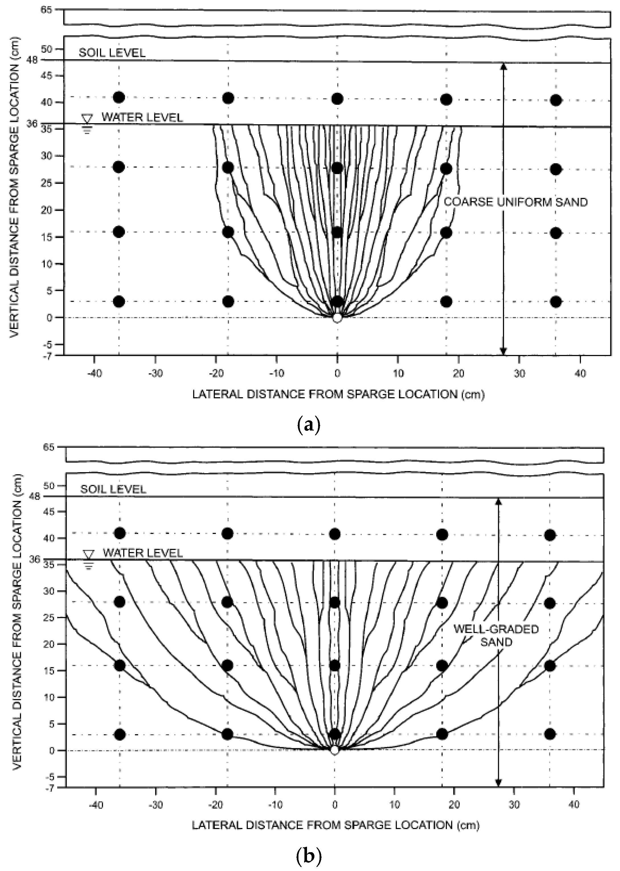
Reddy and Adams [85] showed that the distribution of injected gas/air into the soil is strongly affected by the kind of soil (Figure 22). In well-graded sands, the size of the zone of influence compared to that of uniform sand increased due to lower air permeability and the increased effect of tortuosity resulting from a wider range of grain-size distribution. Heterogeneous soil profiles were subjected to airflow patterns that were combinations of patterns observed in homogeneous soil profiles. Marulanda et al. [86] investigated the mechanisms controlling the flow of air through saturated porous media during air injection through centrifuge tests.
Sr can be monitored through resistivity measures [87,88] and P-wave velocity [88]. Flora et al. [62] showed that resistivity measurements should be preferred in complex stratigraphy because P-waves are faster at layer interfaces than the ones travelling in partially saturated soil, and then, Vp can be mispredicted in situ.
Regarding durability, the research is ongoing. However, Okamura et al. [89] demonstrated that bubbles can persist over time. At the Sekiya site, where sand compaction piles were used to ameliorate the liquefaction resistance of loose sand deposits, a large amount of air was exhausted from the casing pipe during sand pile installation, contributing to the destruction of soils in the improved areas. After 26 years, Vp measurements demonstrated that the degree of saturation was lower than 1, and undisturbed specimens revealed that Sr was about 92%. Moreover, Zeybek and Madabhushi [90] performed a series of 1 g vertical sand columns and high-g centrifuge tests. Air-induced partially saturated soils were prepared using an air injection technique. The test results showed that the majority of entrapped air bubbles in soils can persist under several simulated field conditions for a sufficient period of time, indicating the long-term reliability of the mitigation accomplished. Indeed, the same authors, Zeybek and Madabhushi [90], investigated the durability of entrapped air bubbles under 1D upward and downward vertical flow in sand column tests. The tests revealed that the change in Sr mostly took place within the first few hours and remained almost unchanged afterwards. In other words, the majority of air bubbles successfully remained entrapped in the voids of soils. They also examined the durability of air bubbles in soils under hydrostatic conditions at low and high fluid pressure, varying pore fluid pressure and lateral excitation. Analysis of the experimental data suggested that some of the entrapped air bubbles in the partially saturated soils lost their function under these conditions, and this led to an increase in the degree of saturation of the specimens. However, the magnitude of this increase was generally very small indeed.
Generally, desaturation with N2 is considered advantageous for the longevity of ground improvement because N2 has low solubility in the liquid phase. A potential advantage of induced desaturation with bacteria, compared to air injection methods, is that the gas is generated within the pores of the soil rather than being forced into the pores. Air injection methods may be particularly problematic in the finer-grained liquefiable soils with higher values of air entry-level pressure. In this case, air injection pressures may cause fracturing and the introduction of large gas pockets rather than air bubbles distributed throughout the pore fluid. On the other hand, air injection is easier to apply, with practical aspects known due to studies on air sparging.

6.2. Effectiveness of IPS and Design Charts

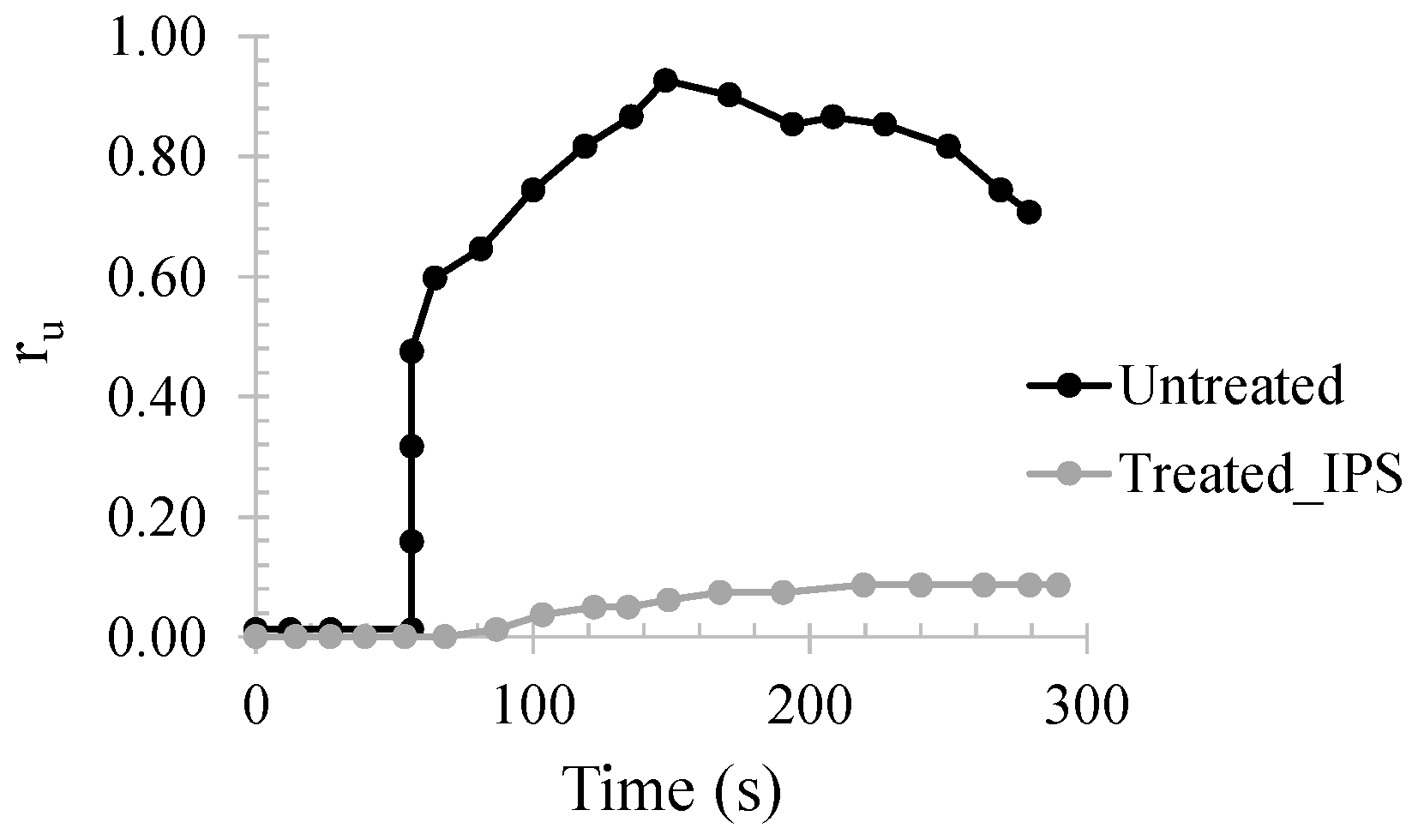
The effectiveness of IPS at a large scale was demonstrated by Flora et al. [88]. The testing site, located in the Pieve di Cento municipality, experienced widespread liquefaction after the mainshock of the 2012 Emilia Romagna seismic sequence (ML 5.9 and ML 5.8 on May 20 and 29, respectively) [91,92]. Within the European project LIQUEFACT (www.liquefact.eu), an extensive in-situ investigation was preliminarily carried out, aiming to define the ground layering and mechanical behaviour of the soils. Ground investigation was integrated with careful laboratory testing (monotonic and cyclic triaxial tests, oedometer tests, cyclic simple shear and cyclic torsional shear tests) on both disturbed and undisturbed specimens. Mitigation interventions were carried out in the shallowest liquefiable layer (2.8 < z < 4.4 m) below the groundwater table, located at about 1.8 m below the ground level. To measure excess pore water pressures and the vertical and horizontal components of soil velocity, pore pressure transducers and bi-directional geophones were placed in each area. A high-energy surface shaker was used to generate the cyclic action. Partial saturation of the soil below the groundwater table was obtained by injecting pressurized air from four sub-horizontal well screens. Five pore pressure transducers and two geophones from the vibrating source were placed into the ground at different depths (z). To evaluate the effectiveness of IPS at a large scale, the results of the shaking tests in the treated area were compared with those in the untreated area. The recorded horizontal acceleration on the base plate of the shaker presents a maximum value of 2.5 g, with a frequency of 10 Hz and a duration of 100 s. Figure 23 shows the comparison between the pore pressure increments in the untreated and treated areas with IPS, highlighting how partial saturation significantly reduces excess pore pressure build-up.
Even though the effectiveness of IPS as a mitigation technique against liquefaction has been verified at small and large scale, this technology is still far from being currently used, also because of the lack of design tools. To contribute to bridge this gap between scientific evidence and engineering practice, a simple design approach for IPS based on the energetic considerations mentioned previously is presented.
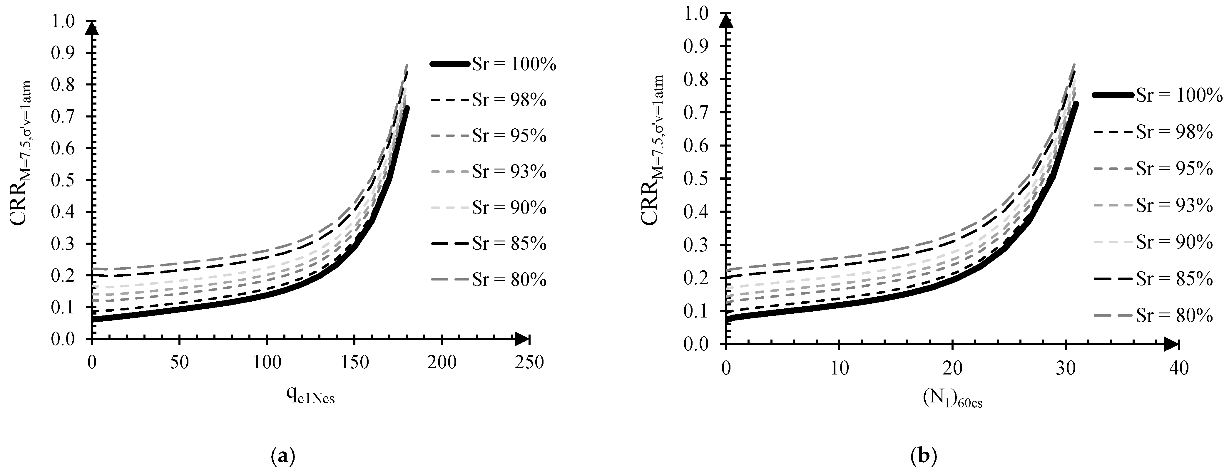
Empirical charts linking CRR to well-known in situ tests results (qc1Ncs and (N1)60cs for CPT and SPT tests, respectively) are common design tools. In order to keep using them to design an IPS intervention, the increment in resistance caused by desaturation has to be introduced to have new, higher values of resistance (CRRns). CPT and SPT-based CRRns curves of partially saturated soils can be easily obtained using the energetic approach proposed in the previous section.
Boulanger and Idriss [93] proposed charts to quantify the cyclic resistance ratio CRRM = 7.5,σ’v = 1 of saturated soils as follows:
C R R M = 7.5 , σ v = 1 = e x p q c 1 N c s 113 + q c 1 N c s 1000 2 q c 1 N c s 140 3 + q c 1 N c s 137 4 2.8   C P T
and
C R R M = 7.5 , σ v = 1 = e x p N 1,60 c s 14.1 + N 1,60 c s 126 2 N 1,60 c s 23.6 3 + N 1,60 c s 25.4 4 2.8   S P T .
Using the energetic approach, the CRRns curves can be obtained (Figure 24a,b) by summing ΔCRR (Equation (28)) to Equations (29) and (30) for the desired degrees of saturation (in Figure 24a,b equal to 98, 95, 93, 90, 85 and 80%) and void ratio (it is possible to calculate Dr as a function of qc1Ncs and (N1)60cs; see, for instance, Boulanger and Idriss [93]).
As discussed above, the upward translation of the saturated curves is possible because, for high values of Sr, there is no mechanical effect of suction on the soil skeleton (i.e., qc1Ncs and (N1)60cs remain constant), even though air and water pressure are slightly different.
The liquefaction risk can be evaluated by comparing the cyclic resistance ratio (CRR) with the cyclic stress ratio (CSR), defined as follows:
C S R = 0.65 a m a x g σ v σ v r d ,
where σv and σ’v are the vertical totals and effective stresses at depth z, amax is the maximum horizontal acceleration, g is the gravity acceleration, and rd is a reduction factor accounting for soil deformability, whose expression can be found in Boulanger and Idriss [93]. Given CRR and CSR, a safety factor (FS) can be quantified for each depth (FS(z) = CRR/CSR)). Saturated soils are susceptible to liquefaction if CSR > CRR, and therefore, FS is lower than 1. The charts in Figure 24 can be used to identify the degree of saturation required in situ to achieve the desired increment in resistance corresponding to the targeted margin of safety. A design example will be shown in the following section.

Use of the Proposed Design Charts for IPS Technique

The case study of Treasure Island (San Francisco, California) can be used as an example to show how to apply the IPS design procedure described in §6.2. Treasure Island is a 400-acre man-made island located immediately northwest of Yerba Buena Island, a rock outcrop in San Francisco Bay. During the 1989 Loma Prieta earthquake, the island was affected by soil liquefaction and other liquefaction-related phenomena (sand boils and lateral spreading) [94]. The soils on Treasure Island may be grouped into four broad categories: the fill material (hydraulic fill) until 13 m from the ground surface, recent bay sediments (Young Bay Mud) from 13 to 28.8 m, native shoal sands (fine to medium sand) from 28.8 to 41.2 m and older bay sediments (Old Bay Clay) from 41.2 to 88 m, at which the bedrock is assumed. The groundwater table is at a depth of 4 m from the ground surface (Figure 25a). CPT test data are available. For the equivalent corrected CPT tip resistance values, qc1ncs, profiles have been achieved considering an average FC equal to 15% [95] (Figure 25b). The potential for the occurrence of liquefaction was evaluated by computing the safety factor (FS). The comparison between CRR (Equation (29) and CSR (Equation (31), using amax = 0.234 g and introducing the magnitude scaling factor (MSF) to account for the effect of the considered magnitude equal to 6.1; [95]), highlights (Figure 25c) that the hydraulic fill layer (4 < z < 13 m) is potentially liquefiable (FS < 1). Hypothesizing the use of IPS, the charts reported in Figure 24a can be used to define the decrease in the degree of saturation needed to improve the in situ soil capacity.
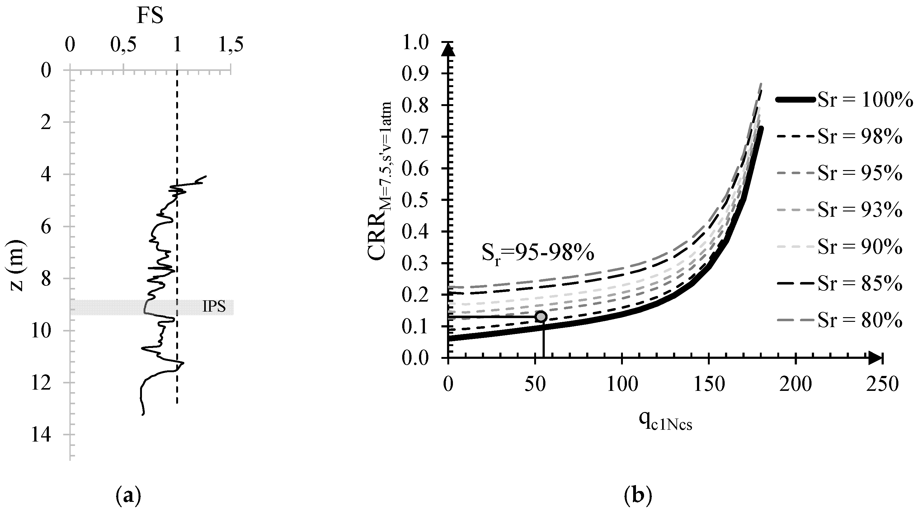
The partial saturation of the soil below the groundwater table can be obtained by injecting pressurized air from sub-horizontal well screens deployed in rows at a depth of 9 m from the ground level, where FS is lower than 0.70 (Figure 26a). In order to guarantee a safety factor FS higher than 1, soil capacity CRR should overcome CSR,max. At 9.0 m (qc1Ncs ≈ 55), CRR should be at least 0.13. The design chart reported in Figure 26b shows that Sr should be at least 95–98%.
Assuming an extension of the soil volume to be treated [62] in terms of length (L1 = 10 m), width (L2 = 4 m) and depth (L3 = 9 m) and considering the mean soil void index (and therefore the void volume Vv), the air volume Va to be injected can be quantified (Sr = (Vv-Va)/Vv). Considering all air retained by the soil, 7.4 m3 of air should be injected. A slight increase (of about 20%) is suggested to account for a certain percentage of injected air lost through the boreholes (Vair ≈ 9 m3). The air must be pumped into the pipes at a pressure (p) high enough to overcome the water hydrostatic pressure but not so high as to generate soil displacement or erosion (i.e., p < 90 kPa for the considered depth). It is worth noting that the degree of saturation can be checked in situ through measurements of compression wave velocity (VP) and soil resistivity (ρ), both of which are sensitive to changes in soil saturation degree.

7. Effect of IPS under Shallow Foundations

Induced Partial Saturation (IPS) is considered one of the most innovative and promising techniques against liquefaction due to its low cost, eco-sustainability and its applicability in urbanised areas, where the need to reduce the risk of liquefaction must be addressed by taking into account the integrity of the existing buildings [96,97]. Therefore, it is important to investigate the effects of IPS under buildings.
Among others, Marasini and Okamura [41] and Zeybek and Madabhushi [43] investigated the liquefaction response of air-injected partially saturated soils beneath shallow foundations by performing a series of centrifuge tests with different bearing pressures.
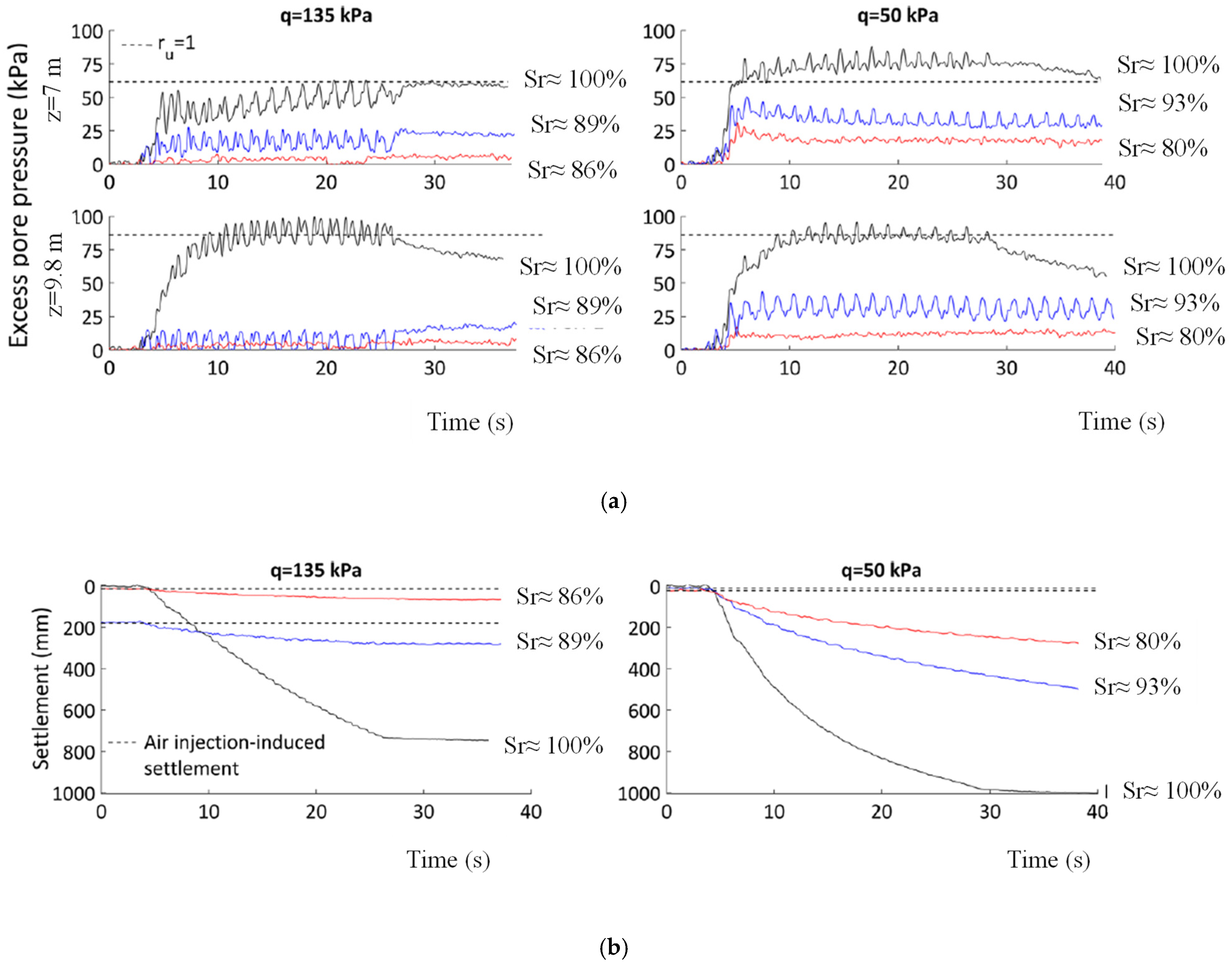
In particular, Zeybek and Madabhushi [43] performed six centrifuge tests at two different bearing pressures (50 and 150 kPa) with degrees of saturation ranging between 80 and 100%. The centrifuge models were prepared and spun at a nominal centrifugal acceleration of 70 g. The schematic illustration of centrifuge models is already shown in Figure 6a. Zeybek and Madabhushi [43] showed that forming spatially distributed partially saturated zones in the liquefiable soils limited the development of high excess pore pressures and liquefaction susceptibility of soils, particularly under higher confining stresses (Figure 27a). Moreover, the reduction in the degree of saturation of soils increases the resistance of soil to bearing capacity failure. Additionally, Zeybek and Madabhushi [43] showed that lower degrees of saturation decrease foundation settlements (Figure 27b). The effect of the degree of saturation on reducing foundation settlements is also dependent on the stress level, and the success of air introduction as a liquefaction mitigation measure is expected to be improved more beneath heavier structures.
Zeybek and Madabhushi [42] investigated the influence of air injection on liquefaction-induced deformation mechanisms beneath shallow foundations, performing centrifuge tests. First of all, they showed that in saturated soils, the deviatoric and volumetric components of shallow foundation settlements are both important, even though the deviatoric strains seem to dominate. Different experimental observations were found when air was injected beneath shallow foundations. In this case, foundation settlements can occur in three different phases: during air injection, during seismic event, and after it, during the dissipation of excess pore water pressure. Zeybek and Madabhushi [42], through the particle image velocimetry (PIV) technique, evaluated soil displacements under shallow foundations during the three phases mentioned above. They showed that in the partially saturated soils, the deviatoric type of deformations under static and dynamic stresses was significantly minimised by the presence of air bubbles, and a complete bearing failure mechanism under the shallow foundation did not occur. However, partial bearing failure can occur during air injection. Indeed, the replacement of pore fluid within the voids of soil by occluded air bubbles occurring during the air injection process can lead to upward migration of pore fluid within soil deposits. It means that in the upper part of soil layers with low confining stresses, the effective stresses drop significantly, and flow-induced liquefaction can take place at these locations. Therefore, it can be suggested that the desaturation of soils beneath existing foundations requires a well-controlled air injection process and close monitoring of foundation response.
In partially saturated soils, the volumetric deformation mechanism due to increased soil compressibility was found to be the primary cause of settlements. In Table 1, the mechanisms of deformations in partially saturated soils under shallow foundations can be summarized.
Based on the experimental results of Zeybek and Madabhushi [42], Zeybek and Madabhushi [98] proposed to calculate liquefaction-induced settlements of partially saturated soils under shallow foundations by neglecting the deviatoric component. They proposed to estimate settlements by summing the settlement related to the compressibility of the fluid phase with the volumetric strains due to the dissipation of excess pore water pressure [99].
However, it is important to mention that although IPS can reduce structural settlements, it tends to amplify structural accelerations. Further studies are needed to better understand this aspect.

8. Discussion and Conclusions

Among several countermeasures against liquefaction, Induced Partial Saturation (IPS) is considered one of the most innovative and promising techniques due to its low cost, eco-sustainability and its applicability in urbanised areas. However, some believe that several “application issues” should be solved before this technique becomes common among practitioners. The main aim of this review is to raise questions and foster discussions among researchers in order to improve knowledge on this topic and overcome the drawbacks linked to in situ applications.
In the first part, insight into the characteristics and behaviour of partially saturated soils is provided. In particular, results from cyclic laboratory tests highlight that the presence of air/gas bubbles in specimens can improve liquefaction resistance due to an increase in fluid compressibility. Several parameters have been proposed in the literature to be responsible for the increase in the liquefaction resistance of partially saturated sands compared to saturated ones. Among those, the most promising is a new state parameter: the volumetric energy to liquefaction (Ev,liq), which stems from the well-known potential volumetric strain (εv*) proposed by Okamura and Soga [27]. Ev,liq seems to be linked to the increase in the liquefaction resistance of partially saturated sands compared to saturated ones. It means that knowing the liquefaction resistance of saturated sands allows for estimating that of partially saturated ones, even though it is important to emphasize that the estimation of liquefaction resistance of partially saturated sands from cyclic laboratory tests should be used with extreme care. Indeed, the low-loading frequency of cyclic tests can strongly affect the solubility of gas in water (Fick’s law). As a consequence, higher volumetric strains can be recorded at the laboratory scale than those obtained during real earthquakes (higher frequencies). In other words, liquefaction resistance can be overestimated.
Ascertaining the effectiveness of IPS to mitigate liquefaction risk, it is important to clarify several aspects linked to the in situ application of IPS.
First of all, it is worth discussing how to desaturate. Several methods have been proposed in the literature, the main ones being air injection, denitrification induced by bacteria, electrolysis of water and chemical methods. According to the authors, air injection and denitrification are the most promising. Air injection is well known among environmental engineers for decontaminating sites from unhealthy volatile substances (air sparging). However, it generates a non-uniform distribution of air bubbles in the soil. On the contrary, denitrification induced by bacteria can produce uniform nitrogen bubbles that are uniformly distributed within the soil deposit. Moreover, the low solubility of N2 in water can guarantee higher durability of the bubbles. The longevity of gas bubbles within the water matrix of soil is a key point in the study of IPS. Preliminary results seem to show that bubbles can persist for long periods of time (more than 26 years). However, further studies are needed.
The IPS-treated volume of soil can be estimated using Vp and resistivity measures. Indeed, both of them are linked to the Sr of the soil.
Moreover, due to the lack of design tools, IPS, as a countermeasure against liquefaction, is not yet common among practitioners. However, recently, some design charts have been proposed. They have been built using the state parameter, Ev,liq, and they allow the identification of the Sr to apply in situ to have a desired value of safety factor (FS). An example is also provided.
In the last part, a brief insight into the effects of IPS under shallow foundations is presented. As expected, results from centrifuge tests show that excess pore water pressure decreases when Sr is lower than 1. Consequently, earthquake-induced settlements of shallow foundations decrease compared to those recorded in saturated soils. However, several results show that structural accelerations are generally amplified. Further studies are needed to clarify this important aspect of buildings.
In conclusion, IPS, as a countermeasure against liquefaction, is effective, economical and eco-friendly; however, continued research is required, especially to improve the knowledge of practical aspects. Good research will allow to improve engineering applications.

Author Contributions

Conceptualization, L.M.; methodology, L.M., S.L. and A.F.; data curation, L.M.; writing—original draft preparation, L.M.; writing—review and editing, S.L. and A.F.; supervision, S.L. and A.F.; project administration, L.M.; funding acquisition, L.M. All authors have read and agreed to the published version of the manuscript.

Funding

This research received no external funding.

Data Availability Statement

The raw data supporting the conclusions of this article will be made available by the authors on request.

Acknowledgments

This work is involved in “ASsessment of seismic Induced Settlements of Multi layered soils under shallow foundAtions and mItigation Risk actions” (SISMAIR) project; Finanziamento Ricerca di Ateneo (FRA-2022), University of Napoli Federico II (Italy).

Conflicts of Interest

The authors declare no conflicts of interest.

References

  1. Lirer, S.; Mele, L. On the apparent viscosity of granular soils during liquefaction tests. Bull. Earthq. Eng. 2019, 17, 5809–5824. [Google Scholar] [CrossRef]
  2. Mele, L. An experimental study on the apparent viscosity of sandy soils: From liquefaction triggering to pseudo-plastic behaviour of liquefied sands. Acta Geotech. 2022, 17, 463–481. [Google Scholar] [CrossRef]
  3. Zhang, X.; Xu, W.; Yi, R.; Gao, H.; Wang, Z.; Liu, L. A unified thixotropic fluid model considering stage characteristics for soil liquefaction. Acta Geotech. 2023, 18, 5755–5771. [Google Scholar]
  4. Sharma, M.; Satyam, N.; Reddy, K.R. State of the art review of emerging and biogeotechnical methods for liquefaction mitigation in sands. J. Hazard. Toxic Radioact. Waste 2021, 25, 03120002. [Google Scholar] [CrossRef]
  5. Karol Reuben, H. Chemical Grouting and Soil Stabilization; American Society of Civil Engineers: Reston, VA, USA, 2003; Volume 536. [Google Scholar]
  6. Zeybek, A.; Madabhushi, S.P.G. Closure to “Simplified procedure for prediction of earthquake-induced settlements in partially saturated soils” by Abdülhakim Zeybek and Santana Phani Gopal Madabhushi. J. Geotech. Geoenviron. Eng. 2021, 147, 07020027. [Google Scholar] [CrossRef]
  7. Pham, T.A.; Sutman, M.; Medero, G.M. Validation, Reliability, and Performance of Shear Strength Models for Unsaturated Soils. Geotech. Geol. Eng. 2023, 41, 4271–4309. [Google Scholar] [CrossRef]
  8. Bishop, A.W.; Blight, G.E. Some aspects of effective stress in saturated and partly saturated soils. Geotechnique 1963, 13, 177–197. [Google Scholar] [CrossRef]
  9. Mitchell, J.K.; Santamarina, J.C. Biological considerations in geotechnical engineering. J. Geotech. Geoenviron. Eng. 2005, 131, 1222–1233. [Google Scholar] [CrossRef]
  10. Houlsby, G.T. The work input to an unsaturated granular material. Géotechnique 1997, 47, 193–196. [Google Scholar] [CrossRef]
  11. Finno, R.J.; Zhang, Y.; Buscarnera, G. Experimental validation of Terzaghi’s effective stress principle for gassy sand. J. Geotech. Geoenviron. Eng. 2017, 143, 04017092. [Google Scholar] [CrossRef]
  12. Kohgo, Y.; Asano, I.; Hayashida, Y. An elastoplastic model for unsaturated rockfills and its simulations of laboratory tests. Soils Found. 2007, 47, 919–929. [Google Scholar] [CrossRef]
  13. Fredlund, D.G. Unsaturated soil mechanics in engineering practice. J. Geotech. Geoenviron. Eng. 2006, 132, 286–321. [Google Scholar] [CrossRef]
  14. Soltani, A.; Azimi, M.; Boroomandnia, A.; O’Kelly, B.C. An objective framework for determination of the air-entry value from the soil–water characteristic curve. Results Eng. 2021, 12, 100298. [Google Scholar] [CrossRef]
  15. Bear, J. Hydraulic of Groundwater; McGraw-Hill Series in Water Resource and Environmental Eng; McGraw-Hill: New York, NY, USA, 1979; 567p. [Google Scholar]
  16. Mousavi, S. Dynamic Performance of Partially Saturated and Unsaturated Soils. Ph.D. Thesis, University of New Hampshire, Durham, NH, USA, 2020. [Google Scholar]
  17. Grozic, J.L.H.; Nadim, F.; Kvalstad, T.J. On the undrained shear strength of gassy clays. Comput. Geotech. 2005, 32, 483–490. [Google Scholar] [CrossRef]
  18. Schuurman, I.E. The compressibility of an air/water mixture and a theoretical relation between the air and water pressures. Geotechnique 1966, 16, 269–281. [Google Scholar] [CrossRef]
  19. Fredlund, D.G. Density and compressibility characteristics of air–water mixtures. Can. Geotech. J. 1976, 13, 386–396. [Google Scholar] [CrossRef]
  20. Rau, G.; Chaney, R.C. Triaxial testing of marine sediments with high gas contents. In Advanced Triaxial Testing of Soil and Rock; ASTM International: West Conshohocken, PA, USA, 1988; pp. 338–352. [Google Scholar]
  21. Pietruszczak, S.; Pande, G.N. Constitutive relations for partially saturated soils containing gas inclusions. J. Geotech. Eng. 1996, 122, 50–59. [Google Scholar] [CrossRef]
  22. Pande, G.N.; Pietruszczak, S. Assessment of risk of liquefaction in granular materials and it’s mitigation. In Proceedings of the International Conference of “International Association for Computer Methods and Advances in Geomechanics (IACMAG)”, Goa, India, 1–6 October 2008. [Google Scholar]
  23. Jablonská, J. Compressibility of the fluid. In Proceedings of the EPJ Web of Conferences, Paris, France, 7–10 October 2014; EDP Sciences: Les Ulis, France, 2014; Volume 67, p. 02048. [Google Scholar]
  24. Mihalache, C.; Buscarnera, G. Controllability criteria for soils saturated by a compressible fluid. J. Eng. Mech. 2016, 142, 04016076. [Google Scholar] [CrossRef]
  25. Seyedi-Viand, S.M.; Eseller-Bayat, E.E. An alternative empirical function to predict air–water mixture bulk modulus for numerical modeling of liquefaction behavior of induced partially saturated sands. Bull. Earthq. Eng. 2021, 19, 1987–2011. [Google Scholar] [CrossRef]
  26. Mele, L.; Marinelli, F.; Lirer, S.; Flora, A. Model prediction of cyclic liquefaction resistance of gassy soils. Acta Geotechnica 2024, 1–21. [Google Scholar] [CrossRef]
  27. Okamura, M.; Soga, Y. Effects of pore fluid compressibility on liquefaction resistance of partially saturated sand. Soils Found. 2006, 46, 695–700. [Google Scholar] [CrossRef]
  28. Mele, L. Experimental and Theoretical Investigation on Cyclic Liquefaction and on the Effects of Some Mitigation Techniques. Ph.D. Thesis, Università degli Studi di Napoli Federico II, Napoli, Italy, 2020. [Google Scholar]
  29. Wang, H.; Koseki, J.; Sato, T.; Chiaro, G.; Tian, J.T. Effect of saturation on liquefaction resistance of iron ore fines and two sandy soils. Soils Found. 2016, 56, 732–744. [Google Scholar] [CrossRef]
  30. Eseller-Bayat, E.E.; Gulen, D.B. Undrained dynamic response of partially saturated sands tested in a DSS-C device. J. Geotech. Geoenviron. Eng. 2020, 146, 04020118. [Google Scholar] [CrossRef]
  31. Mele, L.; Lirer, S.; Flora, A. An energetic interpretation of liquefaction laboratory tests on partially saturated soils. J. Geotech. Geoenviron. Eng. 2022, 148, 04022082. [Google Scholar] [CrossRef]
  32. Molina-Gómez, F.; da Fonseca, A.V.; Ferreira, C.; Caicedo, B. Improvement of cyclic liquefaction resistance induced by partial saturation: An interpretation using wave-based approaches. Soil Dyn. Earthq. Eng. 2023, 167, 107819. [Google Scholar] [CrossRef]
  33. Molina-Gómez, F.; da Fonseca, A.V.; Ferreira, C.; Caicedo, B. Experimental Wave-Based Assessment of Liquefaction Resistance for Different Degrees of Saturation. Geotech. Test. J. 2023, 46. [Google Scholar] [CrossRef]
  34. Baki MA, L.; Cubrinovski, M.; Stringer, M.E.; van Ballegooy, S.; Ntritsos, N. Effects of partial saturation on the liquefaction resistance of sand and silty sand from Christchurch. Soils Found. 2023, 63, 101400. [Google Scholar] [CrossRef]
  35. Okamura, M.; Teraoka, T. Shaking table tests to investigate soil desaturation as a liquefaction countermeasure. In Proceedings of the Seismic Performance and Simulation of Pile Foundations in Liquefied and Laterally Spreading Ground, Davis, CA, USA, 16–18 March 2006; pp. 282–293. [Google Scholar]
  36. He, J.; Chu, J.; Ivanov, V. Mitigation of liquefaction of saturated sand using biogas. In Proceedings of the Bio-and Chemo-Mechanical Processes in Geotechnical Engineering: Géotechnique Symposium in Print 2013, London, UK, 3 June 2013; ICE Publishing: London, UK, 2014; pp. 116–124. [Google Scholar]
  37. Eseller-Bayat, E.; Yegian, M.K.; Alshawabkeh, A.; Gokyer, S. Liquefaction response of partially saturated sands. I: Experimental results. J. Geotech. Geoenviron. Eng. 2013, 139, 863–871. [Google Scholar] [CrossRef]
  38. Peng, E.; Hou, Z.; Sheng, Y.; Hu, X.; Zhang, D.; Song, L.; Chou, Y. Anti-liquefaction performance of partially saturated sand induced by biogas under high intensity vibration. J. Clean. Prod. 2021, 319, 128794. [Google Scholar] [CrossRef]
  39. Lv, M.; Zhang, D.; Ren, H. Evaluation indicators of saturation on partially saturated sand induced by microbial gas. Case Stud. Constr. Mater. 2022, 17, e01641. [Google Scholar] [CrossRef]
  40. Takemura, J.; Igarashi, R.; Izawa, J.; Okamura, M.; Masuda, M. Centrifuge model tests on soil desaturation as a liquefaction countermeasure. In Proceedings of the 17th International Conference on Soil Mechanics and Geotechnical Engineering, Alexandria, Egypt, 5–9 October 2009; IOS Press: Amsterdam, The Netherlands, 2009; Volumes 1–4, pp. 502–505. [Google Scholar]
  41. Marasini, N.P.; Okamura, M. Air injection to mitigate liquefaction under light structures. Int. J. Phys. Model. Geotech. 2015, 15, 129–140. [Google Scholar]
  42. Zeybek, A.; Madabhushi, S.P.G. Influence of air injection on the liquefaction-induced deformation mechanisms beneath shallow foundations. Soil Dyn. Earthq. Eng. 2017, 97, 266–276. [Google Scholar] [CrossRef]
  43. Zeybek, A.; Madabhushi, S.P.G. Centrifuge testing to evaluate the liquefaction response of air-injected partially saturated soils beneath shallow foundations. Bull. Earthq. Eng. 2017, 15, 339–356. [Google Scholar] [CrossRef]
  44. Kumar, R.; Horikoshi, K.; Takahashi, A. Centrifuge testing to investigate effects of partial saturation on the response of shallow foundation in liquefiable ground under strong sequential ground motions. Soil Dyn. Earthq. Eng. 2019, 125, 105728. [Google Scholar] [CrossRef]
  45. Bao, X.; Jin, Z.; Cui, H.; Chen, X.; Xie, X. Soil liquefaction mitigation in geotechnical engineering: An overview of recently developed methods. Soil Dyn. Earthq. Eng. 2019, 120, 273–291. [Google Scholar] [CrossRef]
  46. Ogata, H.; Okamura, M. Experimental study on air behaviour in saturated soil under air injection. In Proceedings of the Symposium on Natural Disaster Prevention, JSCE, Tokushima, Japan, 30–31 October 2006; pp. 89–90. [Google Scholar]
  47. Sills, G.C.; Gonzalez, R. Consolidation of naturally gassy soft soil. Geotechnique 2001, 51, 629–639. [Google Scholar] [CrossRef]
  48. Rebata-Landa, V.; Santamarina, J.C. Mechanical effects of biogenic nitrogen gas bubbles in soils. J. Geotech. Geoenviron. Eng. 2012, 138, 128–137. [Google Scholar] [CrossRef]
  49. He, J.; Chu, J.; Wu, S.F.; Peng, J. Mitigation of soil liquefaction using microbially induced desaturation. J. Zhejiang Univ.-Sci. A 2016, 17, 577–588. [Google Scholar] [CrossRef]
  50. He, J.; Chu, J.; Liu, H. Undrained shear strength of desaturated loose sand under monotonic shearing. Soils Found. 2014, 54, 910–916. [Google Scholar] [CrossRef]
  51. Wang, K.; Chu, J.; Wu, S.; He, J. Stress–strain behaviour of bio-desaturated sand under undrained monotonic and cyclic loading. Géotechnique 2021, 71, 521–533. [Google Scholar] [CrossRef]
  52. O’Donnell, S.T.; Rittmann, B.E.; Kavazanjian, E., Jr. MIDP: Liquefaction mitigation via microbial denitrification as a two-stage process. I: Desaturation. J. Geotech. Geoenviron. Eng. 2017, 143, 04017094. [Google Scholar] [CrossRef]
  53. Mousavi, S.; Ghayoomi, M. Liquefaction mitigation of sands with non-plastic fines via microbial-induced partial saturation. J. Geotech. Geoenviron. Eng. 2021, 147, 04020156. [Google Scholar] [CrossRef]
  54. Yegian, M.K.; Eseller-Bayat, E.; Alshawabkeh, A.; Ali, S. Induced-Partial Saturation for liquefaction mitigation: Experimental investigation. J. Geotech. Geoenviron. Eng. ASCE 2007, 133, 372–380. [Google Scholar] [CrossRef]
  55. Zeybek, A. Shaking table tests on seismic performance of shallow foundations resting on partially saturated sands. Arab. J. Geosci. 2022, 15, 774. [Google Scholar] [CrossRef]
  56. Amini, P.F.; Yang, J. Liquefaction susceptibility of clayey sands under saturated and partially saturated conditions. Géotechnique 2023, 1–39. [Google Scholar] [CrossRef]
  57. Vega-Posada, C.A.; Finno, R.J.; Zapata-Medina, D.G. Effect of gas on the mechanical behavior of medium-dense sands. J. Geotech. Geoenviron. Eng. 2014, 140, 04014063. [Google Scholar] [CrossRef]
  58. Skempton, A.W. The pore-pressure coefficients A and B. Geotechnique 1954, 4, 143–147. [Google Scholar] [CrossRef]
  59. Yang, J. Liquefaction resistance of sand in relation to P-wave velocity. Geotechnique 2002, 52, 295–298. [Google Scholar] [CrossRef]
  60. Astuto, G.; Molina-Gomez, F.; Bilotta, E.; Viana da Fonseca, A.; Flora, A. Some remarks on the assessment of P-wave velocity in laboratory tests for evaluating the degree of saturation. Acta Geotech. 2023, 18, 777–790. [Google Scholar] [CrossRef]
  61. Yang, J.; Sato, T. Interpretation of seismic vertical amplification observed at an array site. Bull. Seism. Soc. Am. 2000, 90, 275–285. [Google Scholar] [CrossRef]
  62. Flora, A.; Chiaradonna, A.; Bilotta, E.; Fasano, G.; Mele, L.; Lirer, S.; Pingue, L.; Fanti, F. Field tests to assess the effectiveness of ground improvement for liquefaction mitigation. In Earthquake Geotechnical Engineering for Protection and Development of Environment and Constructions; CRC Press: Boca Raton, FL, USA, 2019; pp. 740–752. [Google Scholar]
  63. Guo, Y.; Yang, J. Use of shear wave velocity to evaluate in-situ state of silty sands. In Proceedings of the 19th International Conference on Soil Mechanics and Geotechnical Engineering, Seoul, Republic of Korea, 17–21 September 2017; Volume TC102, pp. 603–606. [Google Scholar]
  64. Tamura, S.; Tokimatsu, K.; Abe, A.; Sato, M. Effects of air bubbles on B-value and P-wave velocity of a partly saturated sand. Soils Found. 2002, 42, 121–129. [Google Scholar] [CrossRef]
  65. Sherif, M.A.; Tsuchiya, C.; Ishibashi, I. Saturation effects on initial soil liquefaction. J. Geotech. Eng. Div. 1977, 103, 914–917. [Google Scholar] [CrossRef]
  66. Chaney, R. Saturation effects on the cyclic strength of sands. In Proceedings of the ASCE Special Conference on Earthquake Engineering and Soil Dynamics, New York, NY, USA, 19–21 June 1978; pp. 342–358. [Google Scholar]
  67. Yoshimi, Y.; Tanaka, K.; Tokimatsu, K. Liquefaction resistance of a partially saturated sand. Soils Found. 1989, 29, 157–162. [Google Scholar] [CrossRef] [PubMed]
  68. Xia, H.; Hu, T. Effects of saturation and back pressure on sand liquefaction. J. Geotech. Eng. 1991, 117, 1347–1362. [Google Scholar] [CrossRef]
  69. Ishihara, K.; Tsuchiya, H.; Huang, H.; Kamada, K. Recent studies on liquefaction resistance of sand-effect of saturation. In Proceedings of the 4th International Conference on Recent Advances in Geotechnical Earthquake Engineering and Soil Dynamics, San Diego, CA, USA, 26–31 March 2001. [Google Scholar]
  70. Ishihara, K.; Tsukamoto, Y.; Kamada, K. Undrained behavior of near-saturated sand in cyclic and monotonic loading. In Proceedings of the Cyclic Behavior of Soils and Liquefaction Phenomena, Bochum, Germany, 31 March–2 April 2004; pp. 27–39. [Google Scholar]
  71. Cordeiro, D.; Molina-Gomez, F.; Ferreira, C.; Rios, S.; Viana da Fonseca, A. Cyclic liquefaction resistance of an alluvial natural sand: A comparison between fully and partially saturated conditions. Geotechnics 2002, 2, 1–13. [Google Scholar] [CrossRef]
  72. Wu, J.; Kammerer, A.M.; Riemer, M.F.; Seed, R.B.; Pestana, J.M. Laboratory study of liquefaction triggering criteria. In Proceedings of the 13th World Conference on Earthquake Engineering, Vancouver, BC, Canada, 1–6 August 2004. Paper (No. 2580). [Google Scholar]
  73. Mele, L.; Lirer, S.; Flora, A. Liquefaction triggering of non-saturated sandy soils. Géotechnique Lett. 2023, 13, 35–40. [Google Scholar] [CrossRef]
  74. Chen, G.; Zhou, E.; Wang, Z.; Wang, B.; Li, X. Experimental study on fluid characteristics of medium dense saturated fine sand in pre- and post-liquefaction. Bull. Earthq. Engng. 2016, 14, 2185–2212. [Google Scholar]
  75. Unno, T.; Kazama, M.; Uzuoka, R.; Sento, N. Liquefaction of unsaturated sand considering the pore air pressure and volume compressibility of the soil particle skeleton. Soils Found. 2008, 48, 87–99. [Google Scholar] [CrossRef]
  76. Arab, A.; Shahrour, I.; Lancelot, L. A laboratory study of liquefaction of partially saturated sand. J. Iber. Geol. 2011, 37, 29–36. [Google Scholar]
  77. Huang, Y.; Tsuchiya, H.; Ishihara, K. Estimation of partial saturation effect on liquefaction resistance of sand using P-wave velocity. In Proceedings of the Symposium on Liquefaction Mechanism Prediction and Design Method; 1999; Volume 113, pp. 431–434. [Google Scholar]
  78. Tsukamoto, Y.; Ishihara, K.; Nakazawa, H.; Kamada, K.; Huang, Y. Resistance of partly saturated sand to liquefaction with reference to longitudinal and shear wave velocities. Soils Found. 2002, 42, 93–104. [Google Scholar] [CrossRef]
  79. Yang, J.; Savidis, S.; Roemer, M. Evaluating liquefaction strength of partially saturated sand. J. Geotech. Geoenviron. Eng. 2004, 130, 975–979. [Google Scholar] [CrossRef]
  80. Mele, L.; Flora, A. On the prediction of liquefaction resistance of unsaturated sands. Soil Dyn. Earthq. Eng. 2019, 125, 105689. [Google Scholar] [CrossRef]
  81. Moug, D.M.; Sorenson, K.R.; Khosravifar, A.; Preciado, M.; Young, E.S.; van Paassen, L.; Kavazanjian, E.; Zhang, B.; Stokoe, K.H.; Menq, F.M.; et al. Field trials of microbially induced desaturation in low-plasticity silt. J. Geotech. Geoenviron. Eng. 2022, 148, 05022005. [Google Scholar] [CrossRef]
  82. Sorenson, K.; Preciado, A.M.; Moug, D.; Khosravifar, A.; van Paassen, L.; Kavazanjian, E.; Stokoe, K.; Menq, F. Field monitoring of the persistence of microbially induced desaturation for mitigation of earthquake induced soil liquefaction in silty soil. In Proceedings of the ASCE Lifelines Conference, Reston, VA, USA, 1–3 February 2021; ASCE: Reston, VA, USA, 2021. [Google Scholar]
  83. Hu, L.; Wu, X.; Liu, Y.; Meegoda, J.N.; Gao, S. Physical modeling of air flow during air sparging remediation. Environ. Sci. Technol. 2010, 44, 3883–3888. [Google Scholar] [CrossRef]
  84. Thomson, N.R.; Johnson, R.L. Air distribution during in situ air sparging: An overview of mathematical modeling. J. Hazard. Mater. 2000, 72, 265–282. [Google Scholar] [CrossRef]
  85. Reddy, K.R.; Adams, J.A. Effects of soil heterogeneity on airflow patterns and hydrocarbon removal during in situ air sparging. J. Geotech. Geoenviron. Eng. 2001, 127, 234–247. [Google Scholar] [CrossRef]
  86. Marulanda, C.; Culligan, P.J.; Germaine, J.T. Centrifuge modeling of air sparging—A study of air flow through saturated porous media. J. Hazard. Mater. 2000, 72, 179–215. [Google Scholar] [CrossRef] [PubMed]
  87. Okamura, M.; Takebayashi, M.; Nishida, K.; Fujii, N.; Jinguji, M.; Imasato, T.; Yasuhara, H.; Nakagawa, E. In-situ desaturation test by air injection and its evaluation through field monitoring and multiphase flow simulation. J. Geotech. Geoenviron. Eng. 2011, 137, 643–652. [Google Scholar] [CrossRef]
  88. Flora, A.; Bilotta, E.; Chiaradonna, A.; Lirer, S.; Mele, L.; Pingue, L. A field trial to test the efficiency of induced partial saturation and horizontal drains to mitigate the susceptibility of soils to liquefaction. Bull. Earthq. Eng. 2021, 19, 3835–3864. [Google Scholar] [CrossRef]
  89. Okamura, M.; Ishihara, M.; Tamura, K. Degree of saturation and liquefaction resistances of sand improved with sand compaction pile. J. Geotech. Geoenviron. Eng. 2006, 132, 258–264. [Google Scholar] [CrossRef]
  90. Zeybek, A.; Madabhushi, G.S.P. Durability of partial saturation to counteract liquefaction. Proc. Inst. Civ. Eng.-Ground Improv. 2017, 170, 102–111. [Google Scholar] [CrossRef]
  91. Fioravante, V.; Giretti, D.; Abate, G.; Aversa, S.; Boldini, D.; Capilleri, P.P.; Cavallaro, A.; Chamlagain, D.; Crespellani, T.; Dezi, F.; et al. Earthquake geotechnical engineering aspects of the 2012 Emilia-Romagna earthquake (Italy). In Proceedings of the 7th International Conference on Case Histories in Geotechnical Engineering, Chicago, IL, USA, 29 April 29–4 May 2013. [Google Scholar]
  92. Lai, C.G.; Bozzoni, F.; Mangriotis, M.D.; Martinelli, M. Soil liquefaction during the 20 May 2012 M5. 9 Emilia earthquake, Northern Italy: Field reconnaissance and post-event assessment. Earthq. Spectra 2015, 31, 2351–2373. [Google Scholar] [CrossRef]
  93. Boulanger, R.W.; Idriss, I.M. CPT and SPT Liquefaction Triggering Procedures; Report No UCD/GCM-14/01; University of California at Davis: Davis, CA, USA, 2014. [Google Scholar]
  94. Hanks, T.C.; Brady, A.G. The Loma Prieta earthquake, ground motion, and damage in Oakland, Treasure Island, and San Francisco. Bull. Seism. Soc. Am. 1991, 81, 2019–2047. [Google Scholar] [CrossRef]
  95. Chiaradonna, A.; d’Onofrio, A.; Bilotta, E. Assessment of post-liquefaction consolidation settlement. Bull. Earthq. Eng. 2019, 17, 5825–5848. [Google Scholar] [CrossRef]
  96. Rodríguez, C.A.; Rodríguez-Pérez, Á.M.; López, R.; Hernández-Torres, J.A.; Caparrós-Mancera, J.J. A finite element method integrated with Terzaghi’s principle to estimate settlement of a building due to tunnel construction. Buildings 2023, 13, 1343. [Google Scholar] [CrossRef]
  97. Rodríguez, C.A.; Rodríguez Pérez, Á.M.; López, R.; Caparrós Mancera, J.J. Comparative analysis and evaluation of seismic response in structures: Perspectives from non-linear dynamic analysis to pushover analysis. Appl. Sci. 2024, 14, 2504. [Google Scholar] [CrossRef]
  98. Zeybek, A.; Madabhushi, S.P.G. Simplified procedure for prediction of earthquake-induced settlements in partially saturated soils. J. Geotech. Geoenviron. Eng. 2019, 145, 04019100. [Google Scholar] [CrossRef]
  99. Ishihara, K.; Yoshimine, M. Evaluation of settlements in sand deposits following liquefaction during earthquakes. Soils Found. 1992, 32, 173–188. [Google Scholar] [CrossRef]
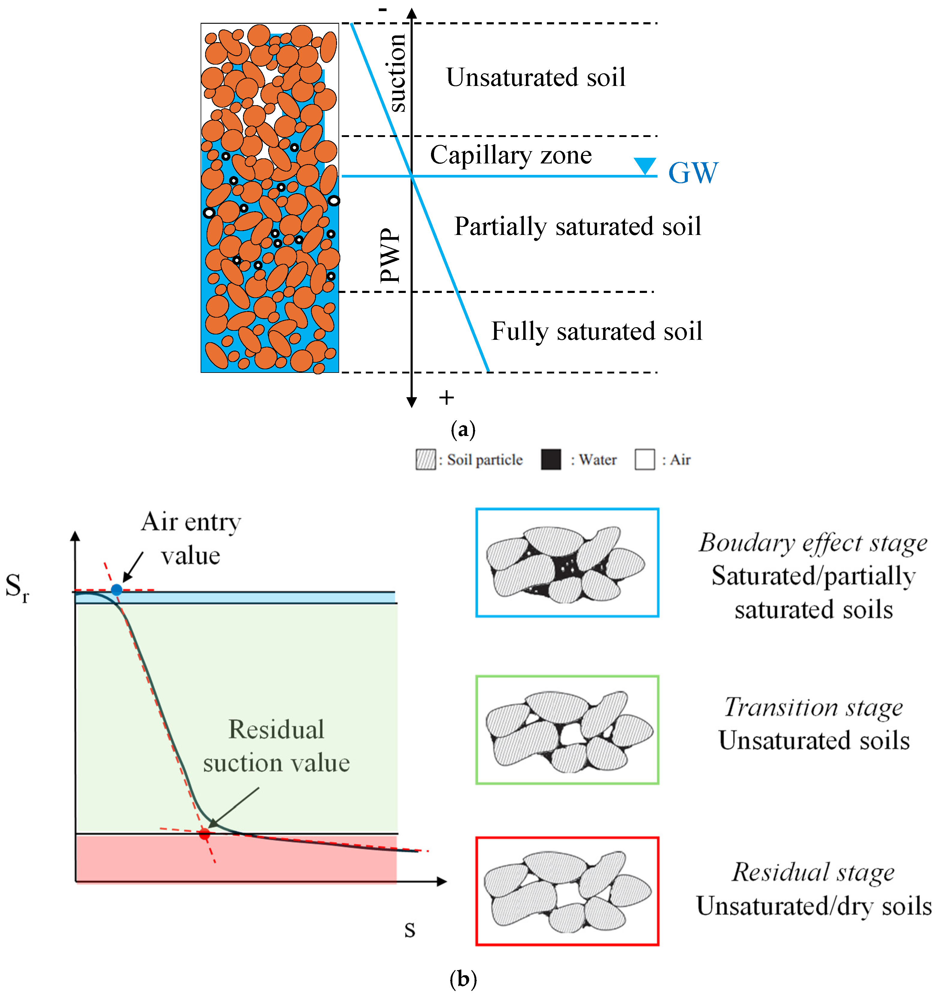
Figure 1. Air distribution in sandy soil deposits (a) (PWP: pore water pressure; GW: groundwater table; modified after [6]) and Soil Water Retention Curve showing different systems of naturally non-saturated soils (b).
Geosciences 14 00140 g001
Figure 2. Sketch of SWRC and three-phase soil element (modified after [16]).
Geosciences 14 00140 g002
Figure 3. Compressibility of fluid phase versus pore air pressure (a) and degree of saturation (b).
Geosciences 14 00140 g003
Figure 4. Effect of solubility of gas on the compressibility of fluid phase (a) and zoomed-in details (b).
Geosciences 14 00140 g004
Figure 5. Degree of saturation with Ncyc for Sant’Agostino sand (SAS) (a) and Pieve di Cento sand (GSS) (b) [28].
Geosciences 14 00140 g005
Figure 6. Centrifuge model layout (a) and colour of fully saturated soil (green) (b) and partially saturated soil (yellow) (c), where brighter yellows indicate lower degrees of saturation (modified after Zeybek and Madabhushi [43]).
Geosciences 14 00140 g006
Figure 7. Nitrate and nitrite reduction [48].
Geosciences 14 00140 g007
Figure 8. Computer tomography (CT) images of saturated (a,b) and desaturated (c,d) soils with Sr = 94% [49].
Geosciences 14 00140 g008
Figure 9. High-resolution image of a partially saturated specimen prepared with wet pluviation (Sr = 77%) [37].
Geosciences 14 00140 g009
Figure 10. Relationship between Sr and B-value (Equation (16)).
Geosciences 14 00140 g010
Figure 11. Relationship between Sr and P-wave velocity (modified after [62]).
Geosciences 14 00140 g011
Figure 12. Effect of bubble diameter on the relationship between Sr and P-wave velocity [64].
Geosciences 14 00140 g012
Figure 13. Difference between Nliq evaluated according to stress and strain criteria against the degree of saturation (modified after [73]) (a) and zoomed-in range of Sr for IPS (b).
Geosciences 14 00140 g013
Figure 14. Liquefaction resistance curves of partially saturated sands compared to those of saturated ones: Toyoura sand ([27]; (a)) and Pieve di Cento sand ([31]; (b)).
Geosciences 14 00140 g014
Figure 15. Volumetric strain with the number of cycles (a) and ru with εv (b) (modified after [31]).
Geosciences 14 00140 g015
Figure 16. Comparison between the theoretical and experimental volumetric strains (a) and ratio between the experimental and theoretical volumetric strain with Sr0 (b) (modified after [31]).
Geosciences 14 00140 g016
Figure 17. Comparison between the theoretical relationship proposed by Okamura and Soga [27] and experimental data [28,29,31,32,51,68,69,70].
Geosciences 14 00140 g017
Figure 18. Ev,sk,liq in the εv–σ’ns plane (modified after Mele et al. [31]).
Geosciences 14 00140 g018
Figure 19. Comparison between the theoretical relationship proposed by Mele et al. [31] and experimental data [27,28,29,31,32,51,68,69,70] (modified after Mele et al. [31]).
Geosciences 14 00140 g019
Figure 20. Comparisons between experimental data and liquefaction resistance curves simulated with the energetic approach [33,69].
Geosciences 14 00140 g020
Figure 21. Schematic representation of air distributions during air sparging [84]. White arrows indicate the direction of air.
Geosciences 14 00140 g021
Figure 22. Airflow pattern in different soils: uniform (a) and well-graded (b) sands [85].
Geosciences 14 00140 g022
Figure 23. Comparison between the excess pore pressure ratio time histories in treated and untreated areas at 1.5 m (modified after Flora et al. [88]).
Geosciences 14 00140 g023
Figure 24. CPT (a) and SPT (b)-based liquefaction triggering curves for partially saturated soils (modified after Mele [28]).
Geosciences 14 00140 g024
Figure 25. Stratigraphy profile of Treasure Island (a), qc1Ncs profile (b) and results of susceptibility analysis (c) in the upper hydraulic fill (z < 13 m).
Geosciences 14 00140 g025
Figure 26. FS profile (a) and use of design chart to choose Sr to apply (b).
Geosciences 14 00140 g026
Figure 27. Centrifuge test results in terms of excess pore pressure (a) and settlements (b) with time for different degrees of saturation (modified after Zeybek & Madabhushi [43]).
Geosciences 14 00140 g027
Table 1. Mechanisms of deformations in partially saturated soils under shallow foundations (modified after Zeybek and Madabhushi [42]).
Type of DeformationMechanisms of Deformation
During Air InjectionDuring and after Seismic Event
VolumetricPositive volumetric strains due to the decrease in effective stress induced by upward flow and due to the increase in the compressibility of soil matrix;Positive volumetric strains due to the increase in the compressibility of soil matrix;
Negative volumetric strains (expansion) due to the coagulation of air bubbles and upward air escape.Limited volumetric strains due to the re-consolidation during the dissipation of excess pore pressures.
DeviatoricLocalised and partial bearing failure due to strength loss in the foundation soil during upward flow.Limited bearing capacity failure;
Limited cumulative foundation settlements due to shear deformation.
Disclaimer/Publisher’s Note: The statements, opinions and data contained in all publications are solely those of the individual author(s) and contributor(s) and not of MDPI and/or the editor(s). MDPI and/or the editor(s) disclaim responsibility for any injury to people or property resulting from any ideas, methods, instructions or products referred to in the content.