Brief Report

Implementation of the Displacement Discontinuity Method in Geotechnical Case Studies

School of Mineral Resource Engineering, Technical University of Crete, 73100 Chania, Greece
*
Author to whom correspondence should be addressed.
Geosciences 2023, 13(9), 272; https://doi.org/10.3390/geosciences13090272
Submission received: 3 August 2023 / Revised: 1 September 2023 / Accepted: 6 September 2023 / Published: 8 September 2023
(This article belongs to the Section Geomechanics)

Abstract

:
This paper uses the displacement discontinuity method, one of the boundary element methods, to solve two major engineering problems. The first one addresses the safe design of underground excavations in fractured rock masses. The implemented method was used to control the slip of discontinuities passing through a circular opening at 45°. Special contact elements were used to simulate a possible slip on the cracks. At the same time, stress intensity factors (SIFs) were calculated using the gradient elasticity theory (special tip elements where numerical integrations are needed were excluded). The crack propagation due to shear slip occurrence was defined using the criterion of maximum tangential stress at an angle of 71° from the initial crack direction. The second one involved in the crack’s propagation was solved by applying pressure to the circular opening, while a part of it was transferred to the cracks, approximating the mechanism of hydraulic fracture. Finally, the implementation of higher elasticity elements in the cracks provided an accurate estimation of SIFs, showing an error of about 4%, as confirmed by comparisons with existing type I loading solutions.

1. Introduction

Among the various numerical methods used relative to boundary elements, there is the widespread displacement discontinuity method proposed by Crouch [1,2] that is used to solve problems in linear fracture mechanics. This method has an advantage in that it can provide solutions for problems in rock and fracture mechanics. When this method is used to calculate the stress intensity factor (SIF), special tip elements are needed to improve its accuracy [3,4]. The mentioned technique requires the use of numerical integrations, a disadvantage that is overcome with the use of gradient elasticity, in order to accurately calculate the SIF from the crack tip elements in two [5,6] and three dimensions [7]. In geomechanical challenges, boundary element models are frequently employed to compute stresses and displacements around underground excavations. Although inhomogeneity and anisotropy [1,2,8,9] can also be examined using the boundary element method, most of these models assume the rock mass to be a homogenous, isotropic, linearly elastic solid. An example of applying this method in underground excavations where the geometry changes with time is the article of Duesner and Beer [10]. When there are also cracks/joints in the medium, the displacement discontinuity method (DDM) is the most suitable for approaching the problem. It is noted that more effective boundary element methods, such as the direct method and the fictitious stress method, can be combined with the DDM as proposed by Crouch [2]. Since DDM converges rapidly with an increasing number of discretisation elements, it can be used in underground excavations with comparable results.
The existence of joints and faults is a significant risk for underground excavation design, and a special technique for detecting such discontinuities is presented in the paper of Radosław et al. [11]. Many studies have applied various techniques, such as numerical solution methods [12,13,14], to determine instabilities around underground openings. Such an analysis includes the complex potential technique, which calculates lateral instabilities around a circular excavation [15]. In the conference paper by Dac et al. [16], the effect of pulp pressure on borehole stability was modelled, varying from low-pulp pressure (shear failure) (left in Figure 1) to high-pulp pressure values (hydraulic fracture) (right in Figure 1).
In this paper, the constant DDM is used to study the behaviour of cracked circular openings, and it is subjected to a compressive field using contact elements to determine the compliance of the cracked rock mass [17,18]. The methodology can then be applied to study the propagation of symmetric cracks, with the existence of internal pressure in the circular excavation (or borehole). Similar techniques have been used with commercial numerical codes [19,20,21,22,23] to simulate hydraulic fracturing. It is worth mentioning the research study performed by Weber et al. [24], where the extended finite element method (XFEM) was used to study the hydraulic fracturing behaviour of symmetric joints around a borehole depending on the fluid’s viscosity. Moreover, finite elements were used to model the influence of the cohesive process zone in hydraulic fracturing [25].
In particular, the utilization of the displacement discontinuity method in this paper is expected to contribute to the following:
  • The effect of joints in a compressive field on the stability of a circular opening as a function of the friction angle and joint inclination;
  • The effect of the normal and shear stiffness modulus on the stress distribution on the joint surfaces;
  • Crack propagation in the case of the hydraulic fracture technique, introducing internal pressure to simulate pressurized fluids.
The method is used to solve the nonlinear problem of the slip and/or propagation of an inclined crack in a compressive stress field. Boundary elements generally present difficulties when solving nonlinear problems, but this method has a possibility of overcoming them (the difficulties that boundary elements usually present during the solution of non-linear problems were overcome using the proposed method). In addition, the calculation of SIFs to examine crack propagation is carried out using higher-order gradient elasticity instead of higher-order boundary elements, which would create large systems that require solutions.

2. The Displacement Discontinuity Method

The method is based on the analytical elastic solutions generated when displacement discontinuity, D i , is applied to a straight-line segment representing the joint. Displacement discontinuity is defined as the total relative displacement of the two surfaces according to Equation (1):
D i = u i u i + ,   i = 1 , 2
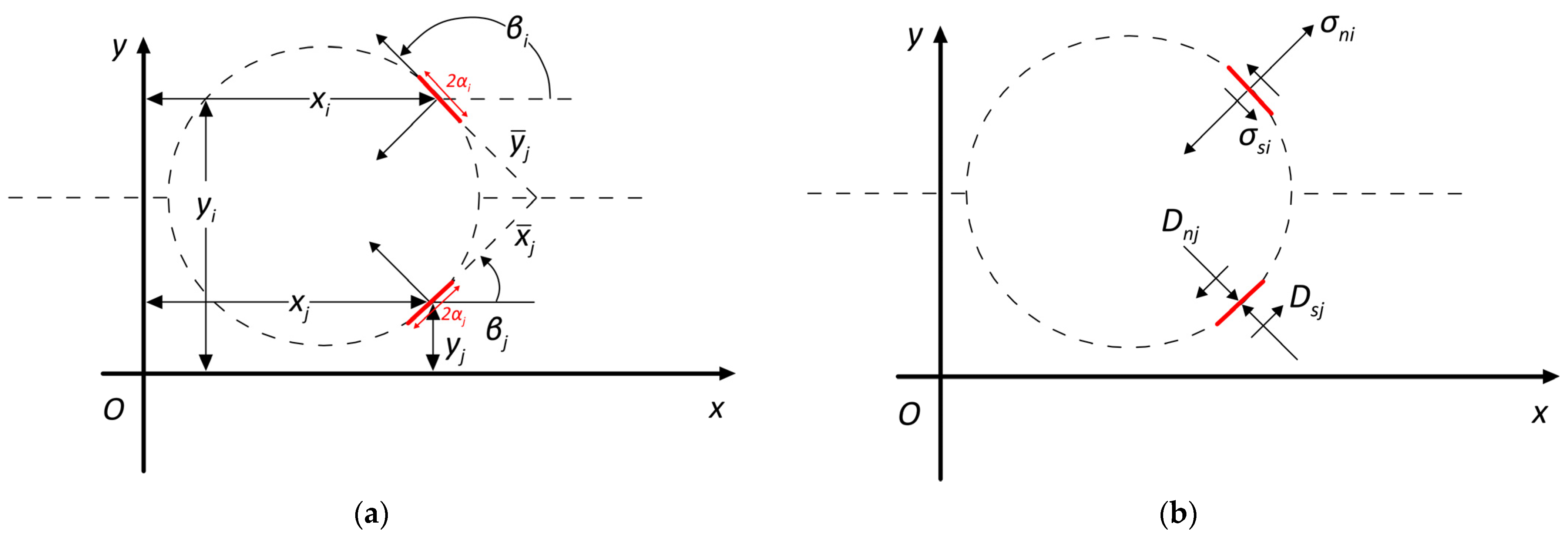
The definition shows that the displacement discontinuity is positive for compressive loading, as shown in Figure 2. This figure shows the local system of the element (discontinuity) with size 2 a   x ¯ , y ¯ placed at its centre x 0 , y 0 , and it forms an angle, β , relative to the horizontal axis of the global system x , y .
The system of equations 2 n   ×   2 n with unknown shear D s and normal D n displacement discontinuities (subscripts s and n denote x ¯ and y ¯ , respectively) is then solved using the description of shear σ s i and normal σ n i stresses (Neumann):
σ s i = j = 1 n A s s i j · D s j + A s n i j · D n j σ n i = j = 1 n A n s i j · D s j + A n n i j · D n j ,   i = 1 , 2 , , n
where either shear u s i and normal u n i displacements (Dirichlet) are described:
u s i = j = 1 n B s s i j · D s j + B s n i j · D n j u n i = j = 1 n B n s i j · D s j + B n n i j · D n j , i = 1 , 2 , , n
or mixed boundary conditions with descriptions of u s i , σ n i or σ s i , and u n i are obtained. The coefficients of the method are denoted by A for the stresses, and B denotes displacements.
To determine A and B, the distance vector between the two arbitrary elements   i and j expressed on the local system of j needs to be calculated first; then, the stress tensor or the displacement vector in the local system of i needs to be transformed according to the procedure described in Figure 3. Figure 3a shows the distance vector x ¯ j , y ¯ j of elements i   and j regarding the local system of the latter, and it is used to estimate the influence of displacement discontinuities D s j , D n j on i (Figure 3b). This is achieved via the application of the appropriate transformations on its local system based on the orientation of element i with respect to j ( β i β j ).
One of the main objectives in crack problem analyses in the context of linear elastic fracture mechanics (LEFM) is to obtain values of SIFs KI, and KII at the crack tips. A way to accomplish this is to use the known LEFM relationships:
K Ι = G 4 · 1     v · lim r 0 2 · π r · D n r G 4 · 1     v · 2 · π a · D n a K Ι I = G 4 · 1     v · lim r 0 2 · π r · D s r G 4 · 1     v · 2 · π a · D s a
where K Ι and K Ι I denote mode I (tension) and mode II (shear) SIFs, respectively:
a is the half size of the tip element;
G is the shear modulus;
v is the Poisson ratio;
r is the distance from the crack tip;
a is half the tip’s element size.
Systematic errors are introduced in SIF’s estimation with Equation (4); therefore, the use of special elements at the tips is needed in the following form:
D i ξ = a ± ξ a , a   ξ a
with minus (−) denoting the right tip and plus (+) denoting the left tip. The corresponding coefficients, A   a n d   B , can be found in [4].
Alternatively, the theory of higher-order elasticity (G2 grade) using internal length l can be used to better estimate the average stress in areas of stress concentrations by relating stress tensor σ i j with strain tensor ε i j using the following:
σ i j = 1 l 2 2 λ · δ i j · ε k k + 2 · G · ε i j
λ   a n d   G are Lame’s elastic constants;
2 are Laplace’s operator;
δ i j are Kronecker delta (0 in non-diagonal and 1 in diagonals) and ε k k = ε 11 + ε 22 .
The A   a n d   B coefficients can be found in [5,6].
It is worth mentioning that DDM has the advantages and disadvantages of the boundary element methods. The basic limitations of the DDM are summarized in the following:
  • The solution is found by solving smaller linear equation systems than using finite element/finite difference methods, but the matrixes are dense (without zeroes), requiring the highest computational effort for obtaining a solution.
  • It is hard to apply in a non-linear medium.
  • The stress field is very large near the tip of each element, so appropriate discretization should be chosen to avoid instabilities in the solution.
  • Additionally, for DDM, tangential stresses require corrections using a finite difference scheme.

3. Displacement Discontinuity Solutions

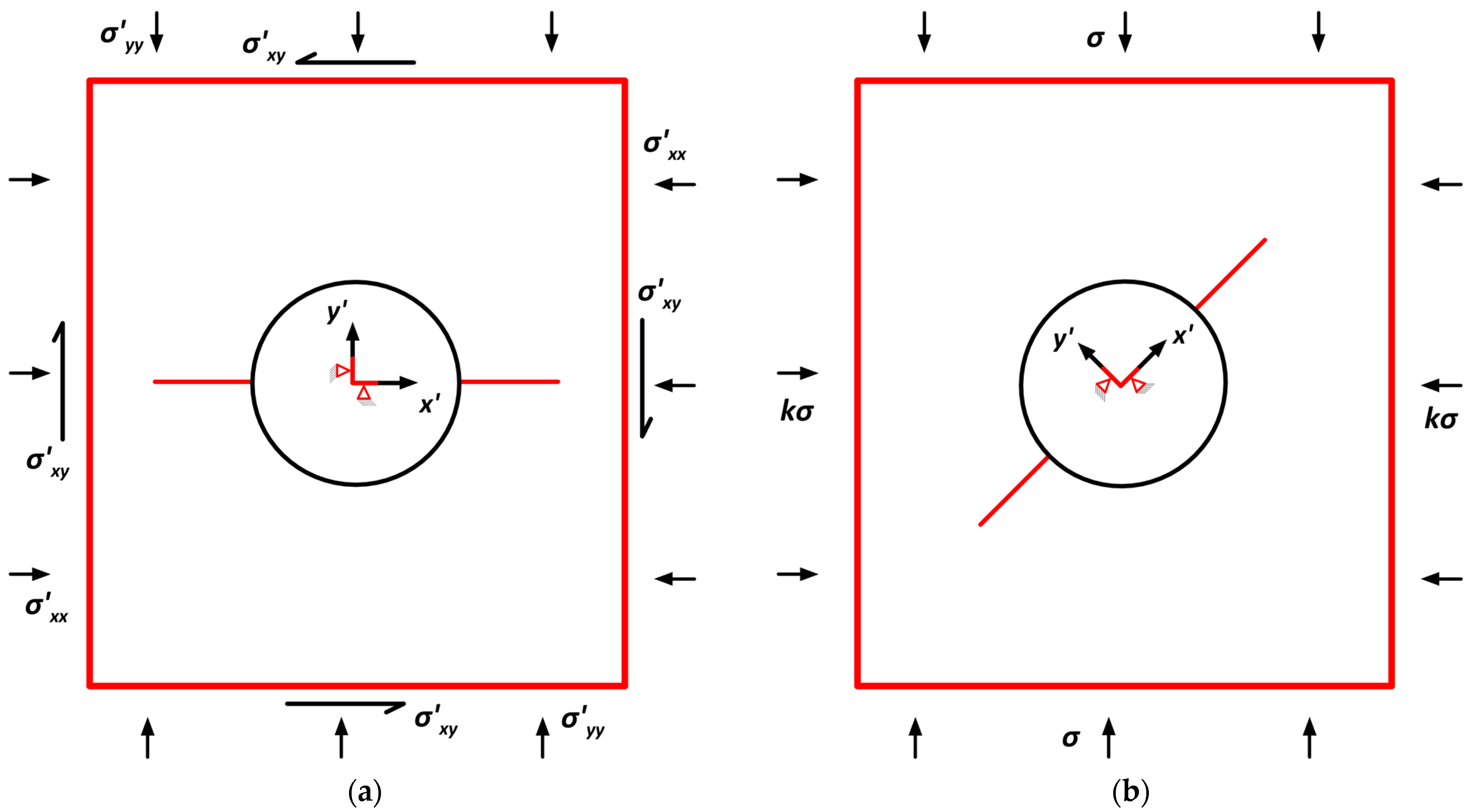
The geological regime affected by complicated structures is crucial for underground excavations, mining, and borehole drilling. The problem to be solved is presented in Figure 4, where the loading of the inclined cracks (Figure 4b) under biaxial compression is equivalent to the solution of the rotated one presented in Figure 4a. In the latter figure, the horizontal crack is subjected to biaxial compression and shear stress resulting from the rotation of the tensor with the angle of discontinuity inclination β (in the counterclockwise direction).

3.1. Contact Element Solutions

The algorithm presented in Crouch’s book [2] is applied to check whether the crack elements are sliding or not. In this methodology, the initial stress field is applied to the elements of the excavation, and it is gradually reduced until the surface stresses are zero (unsupported excavation). At each stage, whether a crack element slips is checked by applying the Mohr–Coulomb criterion for the case of compressive stresses ( σ n ( i ) 0 ):
σ s i   σ n i · t a n φ i = σ s i *
φ i is the friction angle of the ith joint element.
The linear solution system is formulated as follows using k p = 1 , 2 , Κ steps:
  • For the excavation elements ( 1 i n 1 , 1 j n ) ,
    A i j = A s s i j A i n + j = A s n i j A n + i j = A n s i j A n + i n + j = A n n i j Β i = k p Κ · 1 2 · σ y y σ x x · s i n 2 · β i + σ x y · c o s 2 · β i Β n + i = k p Κ · σ x x · s i n 2 β i σ x y · s i n 2 · β i + σ y y · c o s 2 β i
  • For two stabilization elements (Figure 4) ( n 1 + 1 i n 1 + 2 , 1 j n ) ,
    A i j = Β s s i j A i n + j = Β s n i j A n + i j = Β n s i j A n + i n + j = Β n n i j Β i = 0 Β n + i = 0
  • For the crack elements in the non-slip case ( n 1 + 2 < i , 1 j n ) ,
    A i j = A s s i j + K s · δ i j A i n + j = A s n i j A n + i j = A n s i j A n + i n + j = A n n i j + K n · δ i j Β i = σ s i ( k 1 ) σ x y + K s · D s i ( k 1 ) Β n + i = 0
  • Finally, for sliding elements, the above system is modified ( n 1 + 2 < i , 1 j n ) :
    A i j = A s s i j A i n + j = A s n i j A n + i j = A n s i j A n + i n + j = A n n i j + K n · δ i j Β i = ± σ s i * ( k 1 ) σ 12 Β n + i = 0
Note that in the case where the elements lose contact σ n ( i ) 0 , Equation (8) is applied. Solving the system provides the displacement discontinuities at the current step:
X = A 1 · B D s i k = X i ,   D n i k = X n + i  
where the stresses in the current step are calculated using the following relations:
σ s i ( k ) = σ x y + j = 1 n A s s i j · D s j ( k ) + A s n i j · D n j ( k ) σ n i ( k ) = σ y y + j = 1 n A n s i j · D s i ( k ) + A n n i j · D n j ( k )  

3.2. Solutions of an Inclined Crack in a Compressive Field

To solve the problem of the circular tunnel (or a borehole) with a radius of R = 1   m , the periphery of the latter was discretized using n 1 = 74 elements in the counterclockwise direction. The two symmetrical cracks of length α = 1   m were discretized with n 2 = 14 isoparametric elements each. Finally, inside the circular opening (Figure 4) and away from its boundary, two elements with different slopes were created, where zero displacements are imposed to prevent the movement and rotation of the inner region [2], forming a total of n = n 1 + 2 + 2 · n 2 = 104 elements. Table 1 below shows the elastic parameters of the rock’s and joints’ interfaces.
Based on Figure 4, a tensor rotation is applied to solve the problem of an inclined crack with an angle of β = 45 ° in uniaxial compression ( k = 0 ) σ v = 1   M P a , which provides the equivalent stress tensor for Figure 4a:
σ i j = 1 2 1 2 1 2 1 2 MPa
Applying the algorithm in Section 3.1 for different friction angles and using K = 1000 steps, the results of Figure 5 are obtained. Studying the last left crack element that is in contact with the opening ( i = n 1 + n 2 + 2 ) for friction angles up to 45° (slope of the crack), sliding occurs, while no sliding is observed at larger angles.
Examining the effect of the shear and normal stiffness modulus for the case of a cohesionless joint with an angle of φ = 50 ° (no slip occurs), for small values, the stresses at the interface of the opening discontinuity are close to the initial stress field. This is observed because the crack introduces large elastic deformations. On the contrary, at large values, the estimated stresses tend to the Kirsch solution, as the crack’s existence has little effect on the opening. Figure 6 below shows the shear stresses and their corresponding strengths estimated using normal stresses and the Mohr–Coulomb criterion in Equation (7).
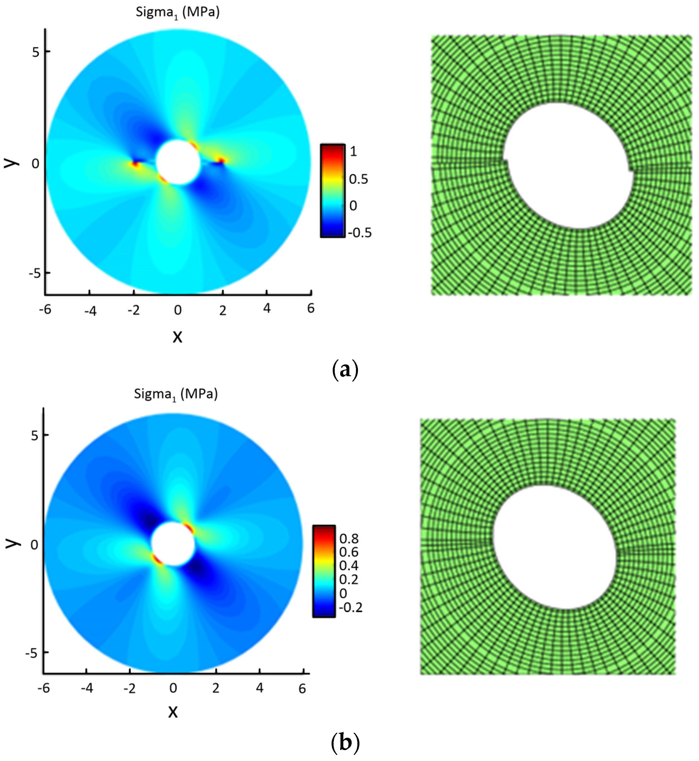
The following results are presented for the φ = 30 ° friction angle case, where all crack elements slide. The left side of Figure 7a with colour shading shows the distribution of the maximum principal stresses occurring at the crown of the tunnel where the maximum compressive is exerted (here, it is shown at 45° since it is in a tilted coordinate system). Figure 7a also shows the concentration of tensile stresses at the crack tip, indicating the direction of propagation. The SIFs for each crack are Κ Ι = 0.04   M P a m and Κ Ι Ι = 0.56   M P a m , and by applying the maximum tangential stress criterion, the possible propagation angle θ c = 71 ° and the tangential SIF Κ θ c = 0.62   M P a m were estimated. The propagation criterion of the maximum tangential stress is given by the following [26]:
t a n θ c 2 = K I K I 2   +   8 · K I I 2 4 · K I I K θ c = c o s 2 θ c 2 · K I · c o s θ c 2 3 · K I I · s i n θ c 2 K I C  
where K I C denotes mode I fracture toughness, and θ c denotes the propagation direction.
The right figure shows the deformation of the opening due to the existence of discontinuities (magnified by 1500). In the case where a friction angle of φ = 50 ° is used, none of the elements slipped, so by using extensive stiffness measures of K s = K n = 10   T Pa/m, it is observed that the influence of discontinuities is eliminated (Figure 7b), and the results are transformed into a solution for the circular opening (Kirsch’s problem). In the left side of Figure 7, the colour scale represents the maximum principal stress (tensile is positive), with the warmer colour representing tensile stresses and the cooler representing compressive stresses.

3.3. Solution with Internal Pressure (Hydraulic Fracturing)

When hydraulic fracturing occurs in an anisotropic stress field, a hydraulic crack is formed and propagates in the direction of the axis where the maximum compressive stress is applied. The pressure transferred to the tip by the fluid depends on the fluid’s viscosity and the crack’s permeability. Below, Figure 8 shows the simulation of the hydraulic fracturing process with fluid leakage into the rock [24].
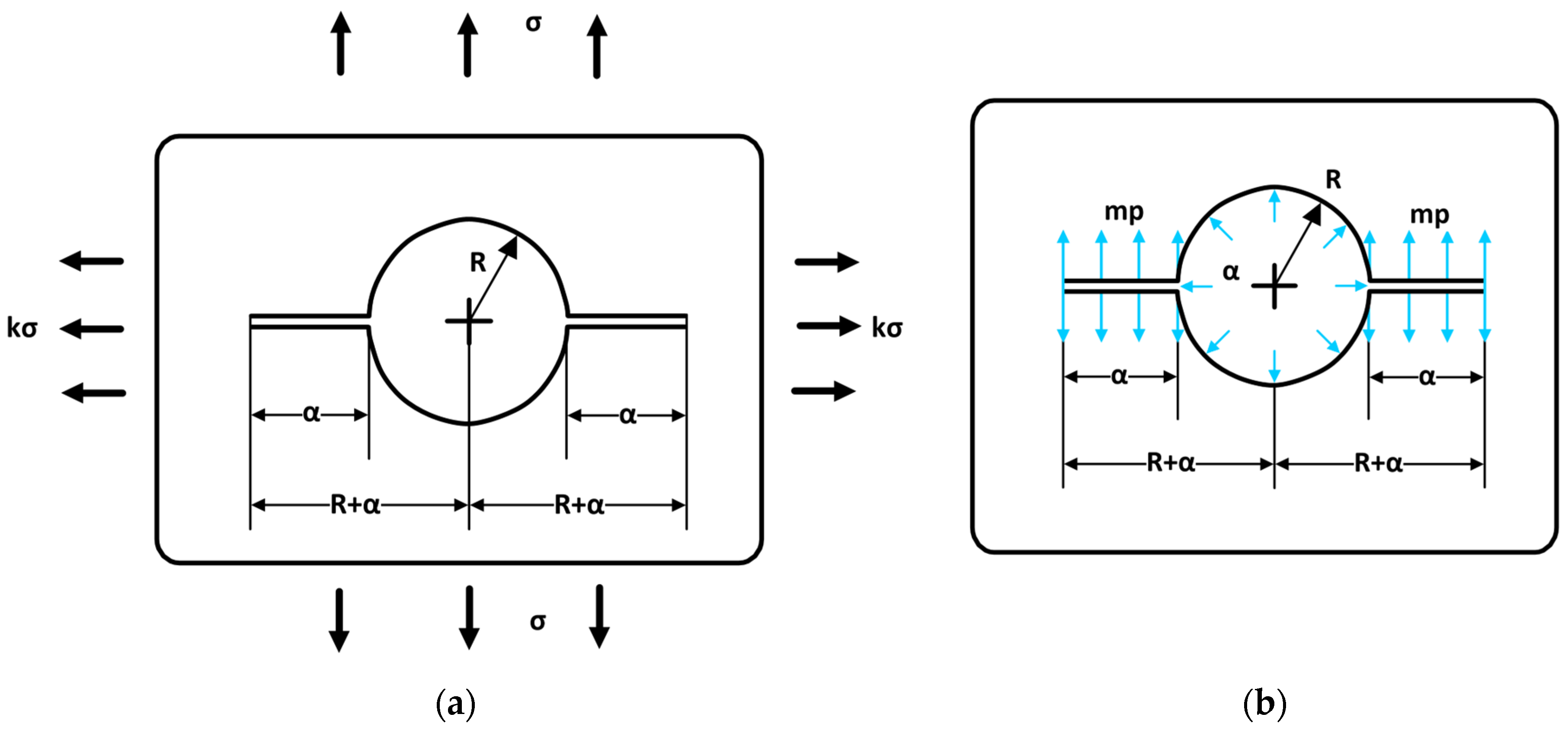
There are solutions for determining mode I SIFs for the approximation of the problem of Figure 9 in the SIFs handbook [27].
The SIF solution is obtained by superposing the solutions of Figure 9 with external stresses and internal pressures:
Κ Ι a = σ · π · a · k · F 0 s + 1 k · F 1 s = π · a · σ x x · F 0 s + σ y y σ x x · F 1 s K I b = p · π · a · m · F 0 s + 1 m · F 2 s ,   0 m 1  
where a is the crack’s length;
p is the inner pressure;
σ x x and σ y y are horizontal and vertical far-field stresses in the local system of the crack;
m is the percentage of pressure transferred into the crack.
F 0 s = 1 + 1 s · 0.5 + 0.743 · 1 s 2
F 1 s = 3 s 2 · 1 + 1.243 · 1 s 3
F 2 s = 1 s · 0.637 + 0.485 · 1 s 2 + 0.4 · s 2 · 1 s
s = a R + a
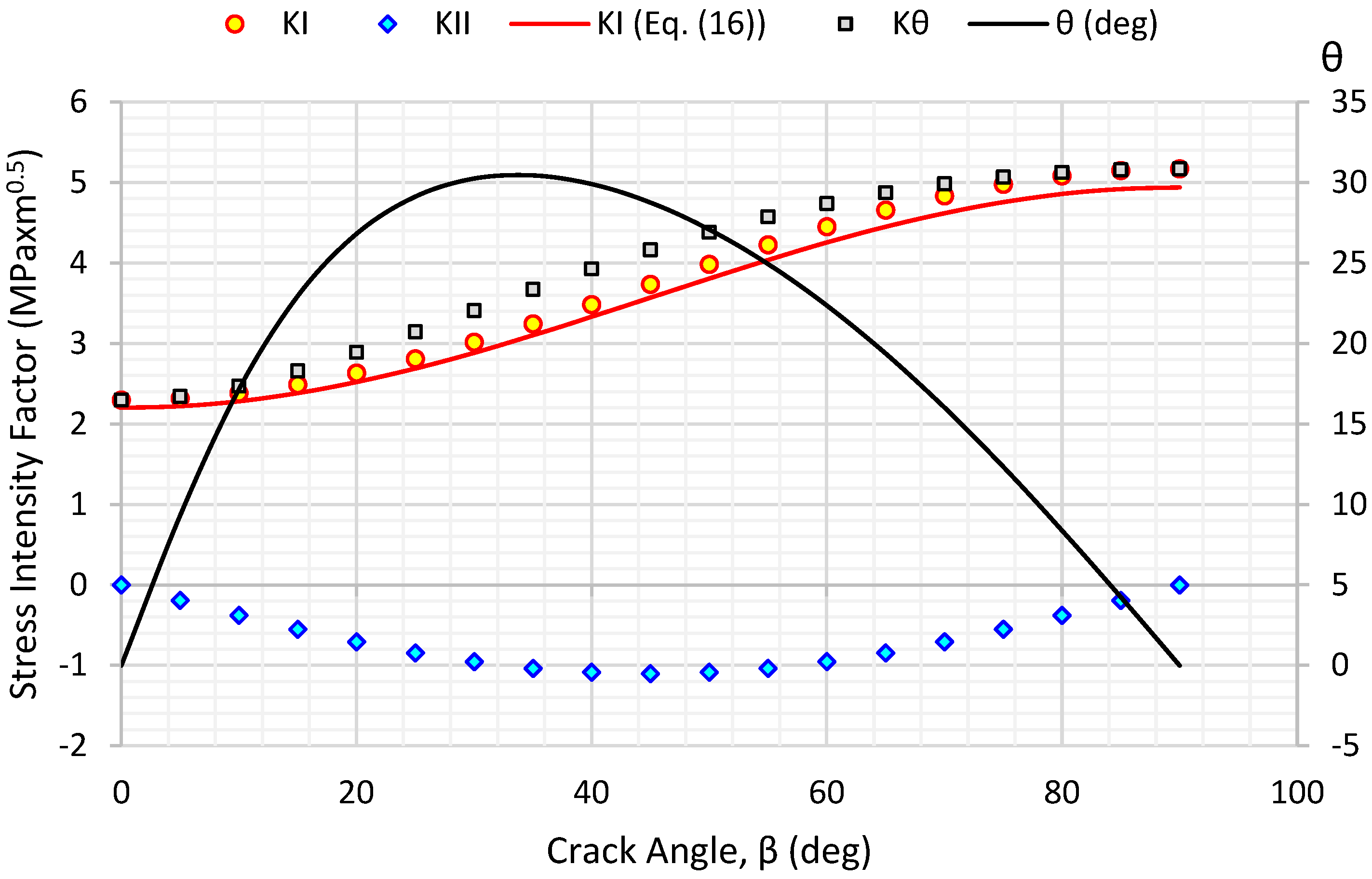
Then, the numerical solution uses 362 elements for the opening, 138 elements for the two cracks, and 2 internal elements for stabilising the inner region. The internal pressure used is k = 0 ,   p = 2   M P a ,   m = 1 ,   σ = 1   M P a , and crack slopes β = 0 90 ° , and the SIF solutions were solved using higher elasticity [6] and assuming that the fluid pressure is applied up to the crack tip at m = 1. The accuracy of the code was checked using the estimates of Equation (16) (presented with a red line in Figure 10) with a relative error of about 4%. As shown in Figure 10, applying the maximum tangential stress criterion of Equation (15) shows that the most straightforward crack propagation is relative to the axis of maximum compressive stress ( β = 90 ° ). In contrast, the crack propagates in a different direction from the original one and at intermediate crack inclinations: β (presented with black line Figure 10). It is noted that the propagation mechanism using the maximum tangential stress propagation criterion is gradually oriented in the direction of the minimum principal stress.
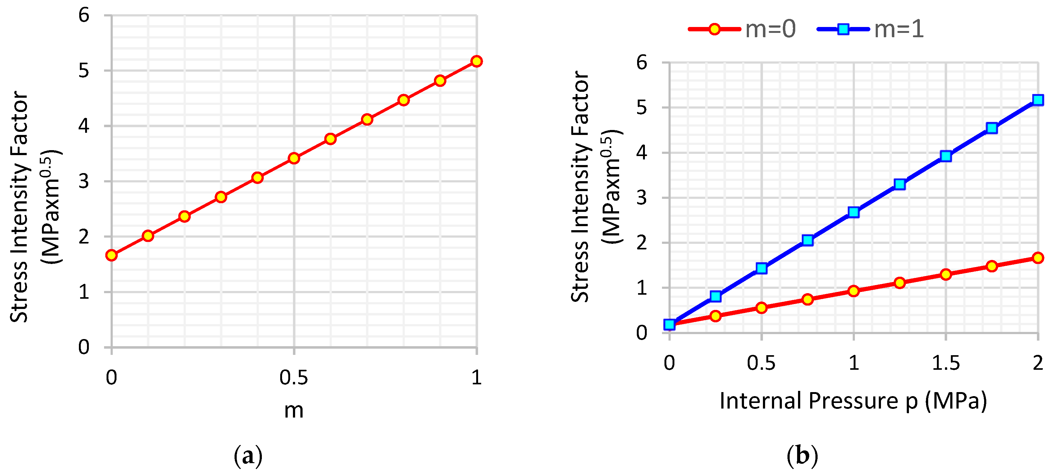
Figure 11 shows the linear dependence of SIFs on the percentage of pressure transferred to the cracks in this simple approximation. The solution for m = 0 is valid for the moment of the application of internal pressure to the circular opening, where the existence of type I (tensile) SIF indicates that the crack is open. The fluid now can more easily penetrate the crack and, depending on its viscosity, gradually reach the complete loading of the entire crack represented by the solution for m = 1. Note that these solutions are valid for hydraulically isolated cracks ( q f = 0 ), and the complete solution is obtained by applying the coupled problem with the poromechanical model [24,28,29].

4. Discussion and Conclusions

The boundary element method and, more specifically, the DDM are powerful and reliable tools for solving problems in which the existence of cracks is involved [30]. Based on this method, the theory of fracture mechanics can be directly applied to define the crack’s propagation direction, which is the unique and essential parameter that requires calculation. In contrast, in finite element application processes, either the reconfiguration of the discretization mesh by using special elements [31] or the monitoring of the crack propagation path is needed to adapt the element’s equations to XFEM methods [24].
Higher-order elements [32] or special tip elements [4] can achieve high accuracy using this method. Still, it creates considerably larger solution systems, and the equations are quite complicated or require numerical integration schemes to find the effect coefficients of the DDM. On the other hand, the gradient elasticity element [5,6,33,34] achieves similarly accurate solutions with smaller systems and relatively simple equations.
DDM was used to study two important problems with respect to mineral resources, geotechnical, and geomechanical engineering, which are as follows:
(a)
In this paper, the effect of the joint interface’s friction angle was investigated on the stability of underground excavations, where the slip occurs for friction angles, φ , that are less than the joint angle, β . When no slip occurs, the shear and normal stiffness, Ks and Kn, of the interface elements play an essential role, and using very high values with respect to stiffness deactivates the existence of the crack. In addition to the sliding of the joint, as demonstrated by Dyskin’s experiments [35], the joint can also propagate in the case of a compressive stress field. The DDM method is a helpful tool for a fast and accurate assessment of the stability of underground excavations provided that the location and orientation of joints need to be determined. A useful monitoring technique for identifying a crucial rock mass defect (joint) that could impact the functionality of underground excavations is presented in the work of Radosław et al. [11].
(b)
The second problem considered here was the effect of internal pressure on the circular opening that simulates hydraulic fracturing, a method that finds applications in hydrocarbon exploitation and wellbore stability. The problem’s complete solution is a multi-factor problem as fluids coexist and alter the behaviour of the medium, and they have been studied by many scientists [19,20,21,22,23]. This paper presents an approach with two limit cases: i) No pressure is transferred at all in the fracture, producing the smallest SIFs, and ii) all pressure is transferred to the fracture’s tip, producing the largest SIFs. The actual SIF values will vary between these two solutions. Also, the accurate estimations of SIFs were proven by carrying out a comparison with the existing mode I solution in the SIF handbook [27], and they were provided by Equation (16). The relative error was found to be less than 4% in the examined case.
This case will be further analysed in subsequent work to solve the coupled model of fluid diffusion in the porous medium by combining the solutions of the finite element/finite difference algorithm with the boundary element algorithm, leading to an estimation of the hydraulic fracture of the medium and the fluid loss based on equations given in the literature [19,20,21,22,23].
In the future, the method can be further improved by properly calculating the internal length l of Equation (6) using the solution itself in an iterative scheme. This will not only simultaneously improve the solutions to crack problems but will also more generally improve the solutions of areas with stress concentrations, such as excavations with an orthogonal cross-section.

Author Contributions

Conceptualization, G.X.; methodology, G.X.; software, G.X.; validation, G.X., G.S. and I.L.; formal analysis, G.X.; investigation, G.X.; data curation, G.X. and I.L.; writing—original draft preparation, G.X.; writing—review and editing, G.S. and I.L.; visualization, G.X., G.S. and I.L.; supervision, G.X. All authors have read and agreed to the published version of the manuscript.

Funding

This research received no external funding.

Data Availability Statement

There is no need for a data availability statement.

Conflicts of Interest

The authors declare no conflict of interest.

References

  1. Crouch, S.L. Analysis of Stresses and Displacements Around Underground Excavations: An Application of the Displacement Discontinuity Method; Second printing; Geomechanics report; University of Minnesota: Minneapolis, MN, USA, 1980; Volume 268. [Google Scholar]
  2. Crouch, S.; Starfield, A.M. Boundary Element Methods in Solid Mechanics; Unwin Hyman: Boston, MA, USA, 1990. [Google Scholar]
  3. Yan, X. Multiple Crack Fatigue Growth Modeling by Displacement Discontinuity Method with Crack-Tip Elements. Appl. Math Model 2006, 30, 489–508. [Google Scholar] [CrossRef]
  4. Yan, X. An Efficient and Accurate Numerical Method of Stress Intensity Factors Calculation of a Branched Crack. J. Appl. Mech. Trans. ASME 2005, 72, 330–340. [Google Scholar] [CrossRef]
  5. Exadaktylos, G.; Xiroudakis, G. The G2 Constant Displacement Discontinuity Method-Part I: Solution of Plane Crack Problems. Int. J. Solids Struct. 2010, 47, 2568–2577. [Google Scholar] [CrossRef]
  6. Exadaktylos, G.; Xiroudakis, G. A G2 Constant Displacement Discontinuity Element for Analysis of Crack Problems. Comput. Mech. 2010, 45, 245–261. [Google Scholar] [CrossRef]
  7. Exadaktylos, G.; Xiroudakis, G.; Stavropoulou, M. Three-Dimensional Elastic Analysis of Rock Excavations by Using the G2 Constant Displacement Discontinuity Method. Procedia Eng. 2017, 191, 1087–1095. [Google Scholar] [CrossRef]
  8. Shen, B.; Shi, J.; Rinne, M.; Siren, T.; Suikkanen, J.; Kwon, S.; Min, K.B. Two-Dimensional Displacement Discontinuity Method for Transversely Isotropic Materials. Int. J. Rock Mech. Min. Sci. 2016, 83, 218–230. [Google Scholar] [CrossRef]
  9. Shou, K.J.; Napier, J.A.L. A Two-Dimensional Linear Variation Displacement Discontinuity Method for Three-Layered Elastic Media. Int. J. Rock Mech. Min. Sci. 1999, 36, 719–729. [Google Scholar] [CrossRef]
  10. Duenser, C.; Beer, G. Simulation of Sequential Excavation with the Boundary Element Method. Comput. Geotech. 2012, 44, 157–166. [Google Scholar] [CrossRef]
  11. Radosław, W.; Waldemar, K.; Łukasz, B.; Waldemar, R. Identification of Rock Mass Critical Discontinuities While Borehole Drilling. Energies 2021, 14, 2748. [Google Scholar] [CrossRef]
  12. Lin, Q.; Cao, P.; Meng, J.; Cao, R.; Zhao, Z. Strength and Failure Characteristics of Jointed Rock Mass with Double Circular Holes under Uniaxial Compression: Insights from Discrete Element Method Modelling. Theor. Appl. Fract. Mech. 2020, 109, 102692. [Google Scholar] [CrossRef]
  13. Lisjak, A.; Mahabadi, O.K.; Kaifosh, P.; Vietor, T.; Grasselli, G. A Preliminary Evaluation of an Enhanced FDEM Code as a Tool to Simulate Hydraulic Fracturing in Jointed Rock Masses. In Proceedings of the Rock Engineering and Rock Mechanics: Structures in and on Rock Masses-Proceedings of EUROCK 2014, ISRM European Regional Symposium, Vigo, Spain, 26–28 May 2014. [Google Scholar]
  14. Liu, B.; Lin, H.; Chen, Y.; Liu, J.; Guo, C. Deformation Stability Response of Adjacent Subway Tunnels Considering Excavation and Support of Foundation Pit. Lithosphere 2022, 2022, 7227330. [Google Scholar] [CrossRef]
  15. Exadaktylos, G.E.; Liolios, P.A.; Stavropoulou, M.C. A Semi-Analytical Elastic Stress-Displacement Solution for Notched Circular Openings in Rocks. Int. J. Solids Struct. 2003, 40, 1165–1187. [Google Scholar] [CrossRef]
  16. Dac, T.N.; My, D.D.T.; Ahmed, A.; Thai, H.P.; Rehman, S.U.; Truong, S.N.; Hong, G.K. Combining Sonic While Drilling and Formation Pressure While Drilling for Pore Pressure Analysis to Reduce Drilling Risk: A Case Study in Offshore Vietnam. In Proceedings of the Offshore Technology Conference Asia, Kuala Lumpur, Malaysia, 22–25 March 2016. [Google Scholar]
  17. Chen, E.; Leung, C.K.Y.; Tang, S.; Lu, C. Displacement Discontinuity Method for Cohesive Crack Propagation. Eng. Fract. Mech. 2018, 190, 319–330. [Google Scholar] [CrossRef]
  18. Wu, H.; Zhao, G.; Liang, W. Investigation of Cracking Behavior and Mechanism of Sandstone Specimens with a Hole under Compression. Int. J. Mech. Sci. 2019, 163, 105084. [Google Scholar] [CrossRef]
  19. Manouchehrian, A.; Kulatilake, P.H.S.W. Numerical Study on Rock Failure around a Tunnel Destressed by a Conceptualized Notched Technique. Undergr. Space 2022, 7, 1086–1097. [Google Scholar] [CrossRef]
  20. Haeri, H.; Sarfarazi, V.; Hedayat, A.; Zhu, Z. Numerical Simulation of Hydraulic Fracturing in Circular Holes. Comput. Concr. 2016, 18, 1135–1151. [Google Scholar] [CrossRef]
  21. Tang, S.; Dong, Z.; Duan, D.; Li, Y. A Theoretical Model for Hydraulic Fracturing through Two Symmetric Radial Perforations Emanating from a Borehole. Adv. Mater. Sci. Eng. 2019, 2019, 6094305. [Google Scholar] [CrossRef]
  22. Wang, S.; Yu, X.; Winterfeld, P.H.; Wu, Y.S. Real-Time Simulation of Hydraulic Fracturing Using a Combined Integrated Finite Difference and Discontinuous Displacement Method: Numerical Algorithm and Field Applications. Water 2023, 15, 938. [Google Scholar] [CrossRef]
  23. Azarov, A.; Patutin, A.; Serdyukov, S. Hydraulic Fracture Propagation near the Cavity in a Poroelastic Media. Appl. Sci. 2021, 11, 11004. [Google Scholar] [CrossRef]
  24. Weber, N.; Siebert, P.; Willbrand, K.; Feinendegen, M.; Clauser, C.; Fries, T.P. The XFEM with an Explicit-Implicit Crack Description for Hydraulic Fracture Problems. In Proceedings of the ISRM International Conference for Effective and Sustainable Hydraulic Fracturing 2013, Brisbane, Australia, 20–22 May 2013. [Google Scholar]
  25. Sarris, E.; Papanastasiou, P. The Influence of the Cohesive Process Zone in Hydraulic Fracturing Modelling. Int. J. Fract. 2011, 167, 33–45. [Google Scholar] [CrossRef]
  26. Erdogan, F.; Sih, G.C. On the Crack Extension in Plates under Plane Loading and Transverse Shear. J. Fluids Eng. Trans. ASME 1963, 85, 519–525. [Google Scholar] [CrossRef]
  27. Tada, H.; Paris, P.C.; Irwin, G.R. The Stress Analysis of Cracks Handbook, 3 rd ed.; ASME Press: New York, NY, USA, 2000. [Google Scholar]
  28. Dang, H.T.; Berre, I.; Keilegavlen, E. Two-Level Simulation of Injection-Induced Fracture Slip and Wing-Crack Propagation in Poroelastic Media. Int. J. Rock Mech. Min. Sci. 2022, 160, 105248. [Google Scholar] [CrossRef]
  29. Wang, J.; Peng, G.; Cong, Z.; Hu, B. Hydraulic Fracture Propagation and Proppant Transport Mechanism in Interlayered Reservoir. Energies 2023, 16, 5017. [Google Scholar] [CrossRef]
  30. Schultz, R.A. Stress Intensity Factors for Curved Cracks Obtained with the Displacement Discontinuity Method. Int. J. Fract. 1988, 37, R31–R34. [Google Scholar] [CrossRef]
  31. Zhang, J.; Yang, W.; Chen, J.; Xu, R. Direct Evaluation of the Stress Intensity Factors for the Single and Multiple Crack Problems Using the P-Version Finite Element Method and Contour Integral Method. Appl. Sci. 2021, 11, 8111. [Google Scholar] [CrossRef]
  32. Crawford, A.M.; Curran, J.H. Higher-Order Functional Variation Displacement Discontinuity Elements. Int. J. Rock Mech. Min. Sci. 1982, 19, 143–148. [Google Scholar] [CrossRef]
  33. Exadaktylos, G. Gradient Elasticity with Surface Energy: Mode-I Crack Problem. Int. J. Solids Struct. 1998, 35, 421–456. [Google Scholar] [CrossRef]
  34. Exadaktylos, G.; Vardoulakis, I.; Aifantis, E. Cracks in Gradient Elastic Bodies with Surface Energy. Int. J. Fract. 1996, 79, 107–119. [Google Scholar] [CrossRef]
  35. Dyskin, A.V.; Sahouryeh, E.; Jewell, R.J.; Joer, H.; Ustinov, K.B. Influence of Shape and Locations of Initial 3-D Cracks on Their Growth in Uniaxial Compression. Eng. Fract. Mech. 2003, 70, 2115–2136. [Google Scholar] [CrossRef]
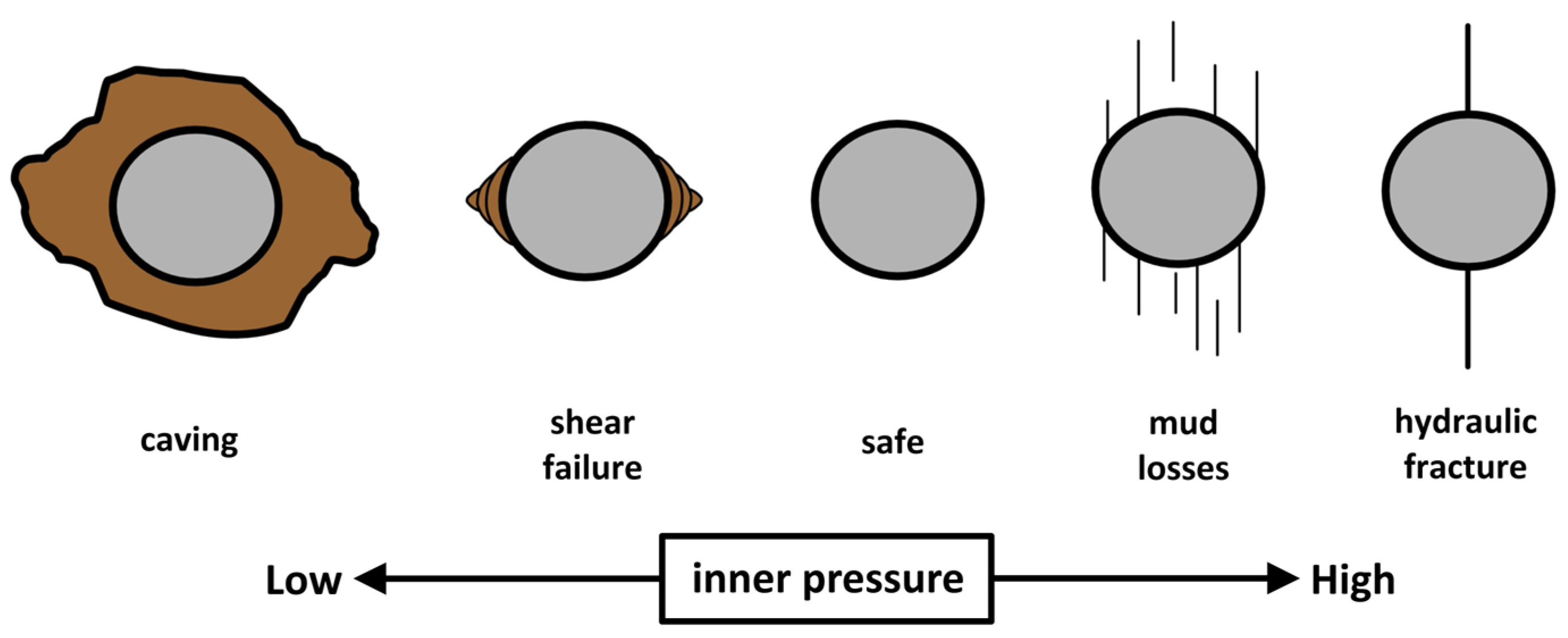
Figure 1. The possible failures around circular openings depending on the internal applied pressure (modified after [16]).
Geosciences 13 00272 g001
Figure 2. Local element system with constant displacement discontinuities [5].
Geosciences 13 00272 g002
Figure 3. The interaction of the two characteristic elements of the boundary depending on the distance vector and their orientation: (a) local element system; (b) effect of displacement discontinuities of j into the i element.
Geosciences 13 00272 g003
Figure 4. Solving equivalent elasticity problems: (a) the local system oriented with the surface of the cracks; (b) the principal stress system.
Geosciences 13 00272 g004
Figure 5. Comparison of applied shear stresses with crack strength as a function of friction angle.
Geosciences 13 00272 g005
Figure 6. The elastic behaviour of cracks compared to the normal stiffness modulus.
Geosciences 13 00272 g006
Figure 7. (a) The results of the maximum principal stresses (tensile) and the deformation of the tunnel at x1500 scale; (b) the corresponding solutions for non-slip stiff crack.
Geosciences 13 00272 g007
Figure 8. The full poromechanical model of hydraulic fracture simulations.
Geosciences 13 00272 g008
Figure 9. The elastic solutions for the type I SIF (a) for biaxial loading and (b) the application of internal pressure with rate m transferred to the crack (modified after [27]).
Geosciences 13 00272 g009
Figure 10. Results of the mixed I-II loading by applying the maximum tangential stress criterion and carrying out comparisons with existing solutions for type I loading.
Geosciences 13 00272 g010
Figure 11. The linear dependence of the SIF with (a) the percentage of pressure in the crack; (b) the pressure in the hole.
Geosciences 13 00272 g011
Table 1. Elastic parameters used in the numerical solution.
ParameterSymbolValueUnit
Young modulusE20GPa
Poisson ratiov0.3-
Shear stiffnessKs100MPa/m
Normal stiffnessKn100MPa/m
Disclaimer/Publisher’s Note: The statements, opinions and data contained in all publications are solely those of the individual author(s) and contributor(s) and not of MDPI and/or the editor(s). MDPI and/or the editor(s) disclaim responsibility for any injury to people or property resulting from any ideas, methods, instructions or products referred to in the content.