Article

Estimation of In Situ Heat Capacity and Thermal Diffusivity from Undisturbed Ground Temperature Profile Measured in Ground Heat Exchangers

by
Claude Hugo K. Pambou
1,*,
Jasmin Raymond
1,
Mafalda M. Miranda
1 and
Nicolò Giordano
2
1
INRS—Institut National de la Recherche Scientifique, 490 rue de la Couronne, Quebec City, QC G1K 9A9, Canada
2
Géotherma Solutions Inc., 13-2528 Avenue de Monceaux, Quebec City, QC G1T 2N7, Canada
*
Author to whom correspondence should be addressed.
Geosciences 2022, 12(5), 180; https://doi.org/10.3390/geosciences12050180
Submission received: 9 March 2022 / Revised: 12 April 2022 / Accepted: 13 April 2022 / Published: 20 April 2022

Abstract

:
Undisturbed ground temperature (UGT), thermal conductivity (TC) and heat capacity (HC) are essential parameters to design geothermal heat pumps and underground thermal energy storage systems, particularly borehole heat exchangers (BHE). However, field methods to assess the thermal state and properties of the subsurface are costly and time consuming. Moreover, HC is often not evaluated in situ but arbitrarily selected from literature considering the geological materials intercepted by boreholes. This work proposes an original empirical approach to reproduce a UGT profile and estimate in situ thermal diffusivity (TD) and HC in the scope of conventional thermal response tests (TRTs). Empirical equations were developed to reproduce a UGT profile measured along a BHE. Experimental coefficients are found with a non-linear least square solver optimization and used to calculate the damping depth, TD and HC. The suggested heat tracing method was verified and validated against other field methods demonstrating to be fast and reliable. The novelty of this new empirical approach relies on the use of a single temperature profile providing a simple way to better assess subsurface thermal properties.

1. Introduction

Thermal response tests (TRTs) made in borehole heat exchangers (BHEs) and analyzed with the infinite line source equation are commonly used to infer in situ thermal conductivity (TC) [1,2,3]. However, the heterogeneity of the ground and the presence of groundwater flow are often neglected to simplify the analysis. Furthermore, estimation of in situ thermal diffusivity (TD) and heat capacity (HC) are also needed when TRTs are combined with the infinite line source equation to reproduce observed temperatures [4].
TRTs analyzed with numerical models or the moving line source equation, for example, are advanced options to characterize the thermal and hydrogeological properties of the subsurface [2,3]. However, developing such numerical or analytical models is a complex task and only provides information on TC and not HC. Core pieces or chip samples can be analyzed in the laboratory in dry or water saturated conditions to better assess thermal storage properties and reduce uncertainty [4,5,6]. However, samples are commonly disturbed and analysis may not be representative of the in situ conditions. Another common simple practice is to arbitrarily select a literature-based in situ HC that matches the geological description of materials found in a borehole [7,8,9,10]. However, a study carried out by Giordano et al. [11] revealed that typical uncertainty associated to the in situ TD is about ±40% when a conventional TRT is analyzed with an approximated HC for common geological materials (1.50 to 3.20 MJ m−3 K−1). All these examples highlight uncertainty that prevails about HC when performing a conventional TRT [4,5]. Therefore, alternative field methods to infer heat storage properties are still needed. Oscillatory TRT (OTRT) proposed and discussed by, for instance, Oberdorfer [12] and applied by Giordano et al. [11], have the potential to evaluate the in situ TD and HC. This methodology is an important step taken towards the in situ evaluation of this thermal property. However, analyzing the oscillating temperature response is complex and the method needs improvement to significantly reduce uncertainty (currently on the order of ±15%). Thus, improving the assessment of ground thermal properties with simple and efficient methods to infer the in situ TD and HC is necessary. Such improvements can help to better design geothermal systems relying on BHEs. Ultimately, this can have a significant positive impact on CO2 emission reduction and provide advantages to develop green energy alternatives [13].
Another available approach for the assessment of TD and HC is the analysis of ground temperature profiles to characterize the thermo-hydraulic properties of the geological materials [3,4,11,14,15,16]. Ground temperature profiles can be acquired with a submersible probe that is lowered into the BHE during or after a TRT [15,16];. These ground temperature profiles can be used to improve the evaluation of in situ TC and estimate horizontal groundwater fluxes [1,3,14,16]. Moreover, ground temperature profiles measured in the BHE before the TRT have also commonly been used to evaluate the undisturbed ground temperature [10,15,16,17]. Numerical modeling can be used to reproduce an equilibrium temperature profile [18]. The resulting profile can be used to extend the conventional in situ TC assessment of a TRT and to infer the terrestrial heat flow [18,19]. Ground temperature profiles measured in observation wells are also used to evaluate other thermal properties such as in situ TD [20,21,22,23,24]. A calculated ground temperature profile using such analytical or numerical approaches can be further matched to the observed ground temperature profile and used to evaluate vertical groundwater fluxes, hydraulic conductivities and thermal properties of the aquifer [22,25,26]. The method is based on the evaluation of the annual amplitude temperature decay and the annual damping depth during long-term observation of the ground thermal disturbance diffusion resulting from the annual thermal flux at the ground surface [24,27,28]. Often, one-dimensional semi-analytical to analytical solutions or numerical simulations are used to infer the ground TD with various methods, such as the amplitude ratio, the phase lag and the harmonic method [10,21,22,23,24,27,28,29,30,31,32]. Despite the potential of these approaches to provide in situ evaluation of TD, they appear hardly applicable to the design of ground-coupled heat pump systems. The main reason is the time required to continuously measure the ground temperature profiles ranging from several days to a year to record a periodic cycle of heat diffusion in the subsurface [10]. As a matter of fact, field measurements of prefeasibility studies for the design of ground-coupled heat pumps must be conducted within a few days, for instance, 2–3 days when considering the heating period of conventional TRTs or up to 5 days if the recovery phase of the TRT is included in the analysis [1,2,3,4,10,11,16,33]. Recently, Márquez et al. [10] proposed a methodology for the indirect evaluation of the in situ TD. This approach assumes transient heat conduction in a semi-infinite medium and is based on the evaluation of the minimum and the maximum mean annual ground temperature measured in a shallow borehole and the depth where that mean annual ambient temperature is observed in the ground. In other words, the method proposed by Márquez et al. [10] is based on the assessment of the depth at which the annual ground temperature remains constant throughout the year (i.e., where there are no seasonal variations). That observed value is called the undisturbed ground temperature (TUGT) [34,35]. The results obtained by Márquez et al. [10] were consistent with TD of mean geological materials identified from a reference borehole. However, this approach requires continuous ground temperature measurements during seven days to a year to identify and confirm the depth where TUGT is located. This field approach is time consuming for a ground-coupled heat pump project. Moreover, the result is sensitive to measurement errors since it is based on a single evaluation of TUGT [21,29,36]. An entire temperature profile may provide more information from the BHE (in terms of geology and thermophysical properties of the geological materials) and thus potentially minimize uncertainty [10,15,16].
All the aforementioned difficulties in assessing accurately and quickly the in situ HC can eventually contribute to increasing errors in the design of geothermal heat pump systems and ultimately impact their installation cost [4,11]. Therefore, evaluating the in situ HC can be useful for simulating the operation of BHEs used for both ground-coupled heat pump and underground thermal energy storage systems [11]. In fact, the Giordano et al. [11] study indicated that the total drilling length of BHEs calculated when designing a ground-coupled heat pump system can be affected by ±6–7%, which influences the total system cost by 3–4%. This highlights that an accurate evaluation of the in situ HC can help to better design ground-coupled heat pump projects by accurately targeting their installation cost and, therefore, positively impacting the geothermal heating and cooling market [4,11,37,38].
Bearing in mind the importance of a quick and accurate assessment of in situ HC, this research study had the objective of developing an alternative heat tracing approach to evaluate in situ HC considering the main guidelines of the TRT [1,2,10,11]. This study was carried out within the scope of a TRT performed in a pilot BHE [10,16]. The resulting method relied on the measurement of a single equilibrium temperature profile that is not disturbed by the heat injection of a TRT or drilling of the BHE and can be recorded before the TRT. Analysis of this equilibrium temperature profile using heat tracing principles allowed the evaluation of in situ TD. Afterwards, HC was calculated based on the in situ TC evaluated with a TRT. This heat tracing method appears rather novel because the in situ HC is evaluated with a single ground temperature profile, which can be the same as evaluating TUGT before performing a conventional TRT. Moreover, using a single observed temperature profile determined at equilibrium and a TC assessment obtained from a conventional TRT analyzed with the slope method provide advantages in terms of simplicity. The methodology proposed does not need additional borehole or several temperature measurements. Finally, it does not depend on prior knowledge of the Earth heat flow since it is only based on an empirical approach to reproduce the observed undisturbed ground temperature profile measured in the BHE.

2. Methodology

2.1. Theoretical Background

General concepts used in this heat tracing method are described below to provide the basis of the new field approach developed and applied in this study. The observed undisturbed ground temperature value (TUGT; °C) and the curve-fit between observed and calculated undisturbed ground temperature profiles are used as a criterion to constrain the analysis in order to infer the damping depth as well as the in situ TD and TC.
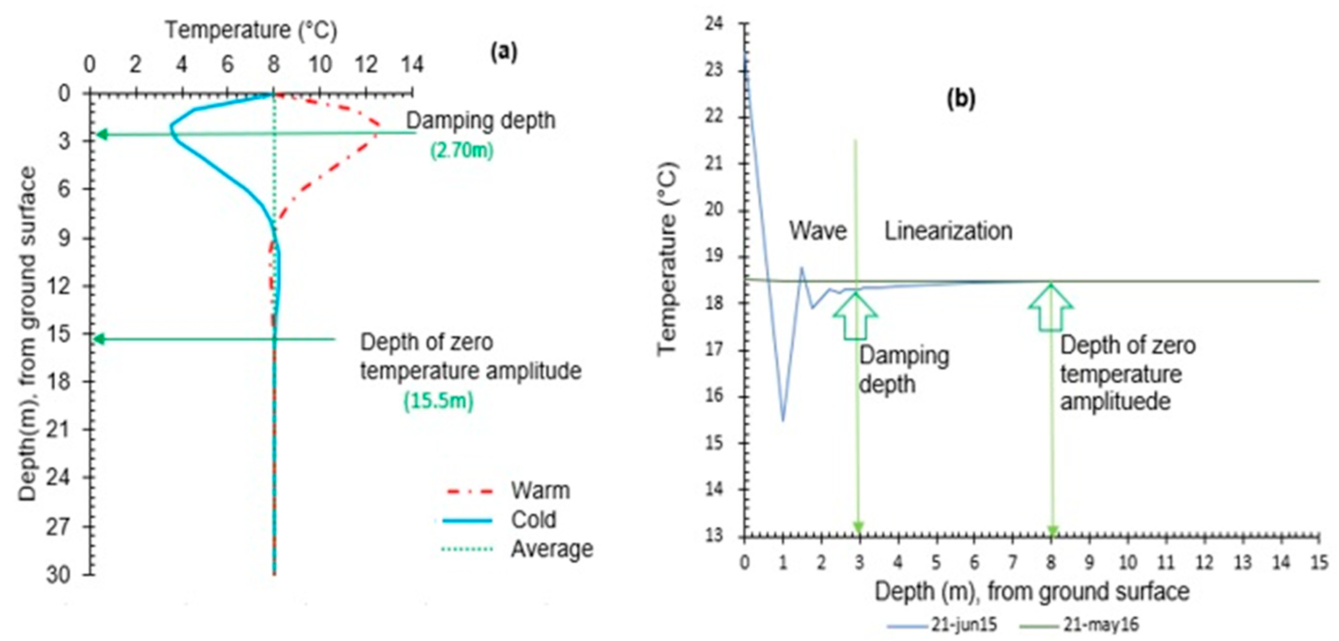
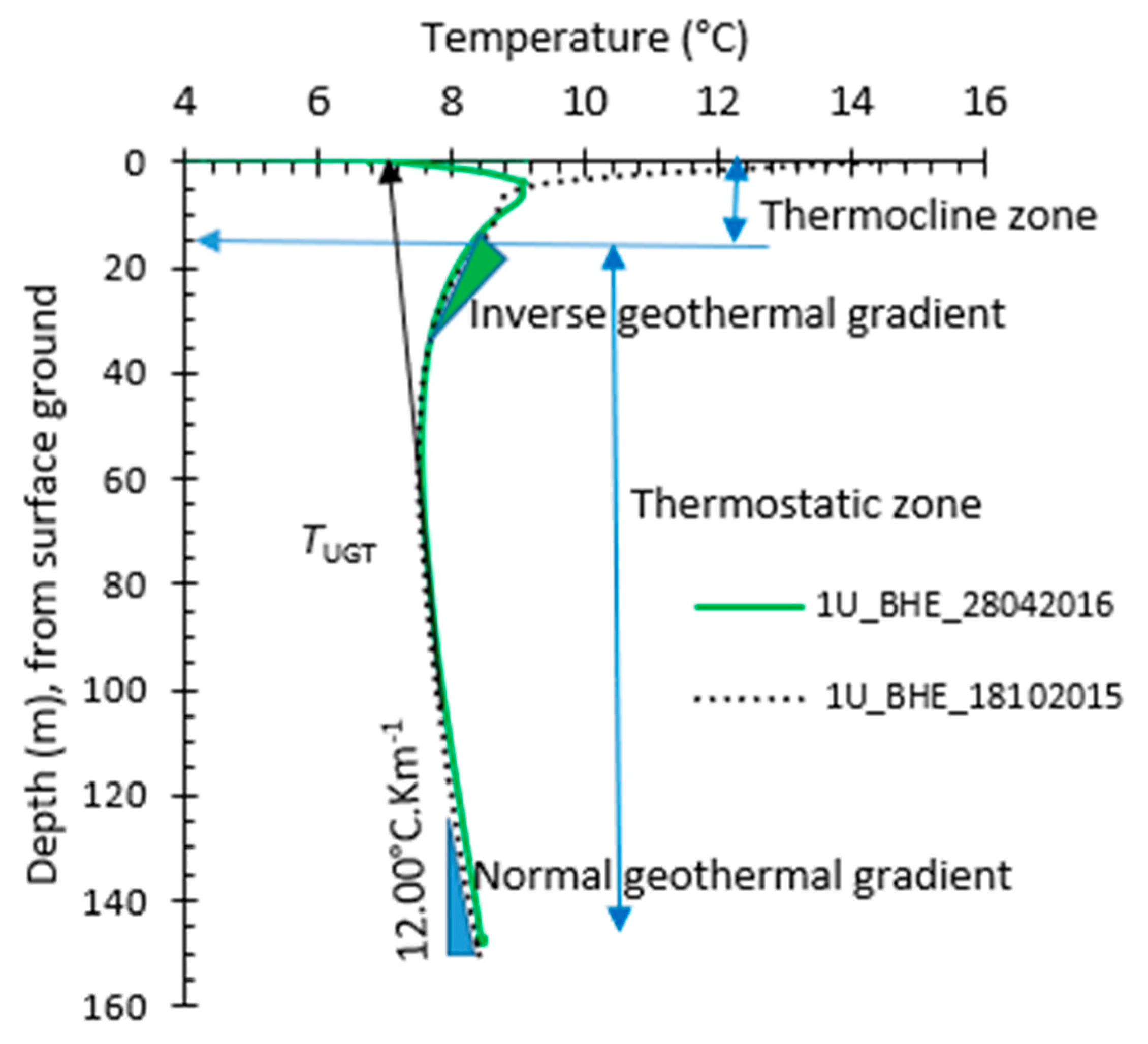
A practical approach to accurately evaluate TUGT is based on the graphical selection of the depth interval to be used for evaluation of the mean ground temperature and discarding near-surface data that visually appears to be affected by surface thermal disturbances [6,9,10,16,34,38]. The depth at which TUGT is found or at which thermal disturbances from the surface are not perceived is called the depth of zero temperature amplitude (Figure 1) and it defines the boundary between thermocline and the thermostatic zones, where the geothermal gradient can be observed [34].
Usually, estimation of the depth of zero temperature amplitude requires monitoring ground temperature profiles at different depths on a yearly basis [9,34], which we want to avoid here to fulfill the TRT practice [3,10,11,16]. For this new method, the acquisition and analysis of ground temperature observations need to be short enough for the test to be reasonably implemented during prefeasibility studies of ground-coupled heat pumps.
Additionally, analysis of the daily ground temperature distribution during seasonal or yearly observations have revealed a near surface depth from where the initial temperature amplitude is damped in the thermocline zone [20,22,28,34,35]. From that damping depth, the wave of the oscillatory surface temperature begins a linear attenuation with depth in the interval located before the thermostatic zone (Figure 2).
A practical approximation ratio is used to evaluate the damping depth by considering the depth where the surface temperature amplitude is reduced to e−1 (1/2.718 = 0.37) of its initial value [20,21,22,23,24,25,26,27,28,29,30,31,32,33,34,35,36,39,40,41]. Beyond the approximation ratio approach, several other mathematical equations have been proposed to evaluate the damping depth. Those are based on the sinusoidal propagation of surface temperature changes in the ground, the mean ambient temperature, or the temperature amplitude variation with depth/time [25,26,27,28,29,30,31,32,33,34,35,36,39,40,41,42]. The mathematical formulations are, for instance, the amplitude decay method, the phase lags method, or the inverse slope of a linear regression method [34,35]. Additionally, Taniguchi [20], Stallman and Gold [25,26] and Tong et al. [28] proposed an analytical parameter method to compute damping depth based on its dependence on subsurface thermal properties (TD, TC and HC) and hydraulic properties (porosity and Darcy flux). However, these listed approaches require a series of ground temperature profile measurements which is time consuming and less attractive when considering the scope of a TRT.
Therefore, a new empirical equation is proposed to compute the damping depth (Equation (5)) from an observed ground temperature profile. It relies on empirical coefficients found by least square method with a solver applied to reproduce the ground temperature profile with calculations. This new empirical equation is described below and was obtained through analysis of the temperature profiles previously acquired during the field implementation of Pambou et al. [18]. Furthermore, it was tested against the sites used by Kusuda et al. [20] and Xing [28]. In this work, the application of the method is shown for TD and HC assessment in the scope of a TRT.

2.2. Model Assumptions and Parameter Estimation Procedure

In this study, it was assumed that an accurate observed TUGT value can be found by averaging ground temperature profile measured in the thermostatic zone [10,17,34,35]. Thermal disturbances caused by surface temperature variations spread by transient heat diffusion in the semi-infinite isotropic and assumed homogeneous subsurface [9,20,21,22,23,24,25,26,27,28,29,30,31,32,33,34]. The latter implies that the diffusion of surface temperature variations can be described by a sinusoidal function or an exponential form of the one-dimension solution governing heat conduction [9,20,21,22,23,24,25,26,27,28,29,30,31,32,33,34].
Theoretical and field results have demonstrated that in situ TD could be evaluated using ground temperature profiles measured in the borehole [9,20,21,22,23,24,25,26,27,28,29,30,31,32,33,34]. Usually, a general equation of the heat conduction or conduction-advection solution is applied to generate ground temperature profiles that are fitted to the observed ground temperature profiles.
Thus, in this project, a ground temperature profile (Tobs (z)) is measured in the BHE before carrying out a TRT. Then, a heat transfer equation can be applied to the observed ground temperature profile, considering TD as an unknown parameter. With this assumption in mind, an empirical equation (Equation (1)) was developed to calculate a normalized ground temperature profile (Tg (z)) of the observed ground temperature (Tobs (z)), in which it is possible to evaluate a damping depth (Zdd) to infer TD by common analytical equation and the calculated undisturbed ground temperature (C1) at the depth of zero temperature amplitude.
A trial-and-error approach could be used to retrieve and approximate C1 and Zdd, but the analysis would be time consuming when considering the scope of a TRT. Therefore, a heat transfer equation (Equation (2)) related to the surface temperature variations and a solver optimization (Equation (3)) are suggested as the fastest method to accurately find C1 and Zdd values. These results are subsequently validated using Equation (4) and the curve-fit of the observed temperature against normalized depth-temperature profiles.
Detailed explanations of each equation used in this proposed heat tracing method are presented in the following subsection.

2.2.1. Calculated Undisturbed Ground Temperature Profile

A new empirical heat conduction equation (Equation (1)) was developed with the goal of calculating a normalized ground temperature profile at any depth z considering the entire length of the BHE. This proposed equation could be used to approximate the one-dimensional solution of the governing heat conduction equation considering a surface temperature diffusion in the half-infinite medium [9,21,23,40,41,42]. The proposed equation was described with an exponential form to normalize each observed ground temperature measurement that made an equilibrium (Tobs (z)) and it is defined as:
T g z     C 1 T bot   T obs ( z ) + 0 . 24615   ×   e 0 . 001257     Z dd   L obs  
where Tg (°C) is the normalized ground temperature at depth over the entire length of the BHE, C1 (°C) is the average ground temperature at the depth of zero temperature amplitude, Tobs (°C) and Tbot (°C) are the observed temperature at any depth and at the bottom of the borehole, respectively, Zdd (m) is the damping depth and Lobs (m) is the length of the borehole surveyed.
Each ground temperature value calculated using Equation (1) is assumed to be a normalized value of the measured ground temperature at each depth over the entire length of the BHE.
Applying the heat balance concept, it is assumed that Zdd and C1 are integrated parameters of the thermocline zone (Figure 1 and Figure 2) and the interpolated undisturbed ground temperature at the depth of zero temperature amplitude when considering one-dimension heat conduction, respectively [19,20,21,22,23,24,27,28,32,33,34]. Therefore, an equation can be used as an upper boundary condition to describe the surface temperature variations transferred to the subsurface by oscillatory heat diffusion [28,33,43,44,45,46]. Thus, a new equation was defined to calculate a ground temperature, as sinusoidal function of the heat diffusion:
T calc z     C 1   +   C 2 ·   e C 3     C 4 · z SIN   2 π     z 0 . 6027315   ·   C 3   + C 4
where C1 (°C), C2 (°C), C3 (m) and C4 (m) are experimental coefficients that can be found by using a non-linear solver optimization (Equation (3)) related to the objective function (OF) and defined as:
O F = 1 N 1 T obs z   T obs z T c a l c z 2
where OF (°C) is the sum of the squared residual computed from the difference between observed and calculated temperature at the same depth and 1 to N is the depth interval distribution covering the total length of the BHE.
The optimization function OF is validated when the bias error (BE) between C1 and the TUGT, inferred from the ground temperature profile measured in the BHE, is less than 5%, such that:
BE   ( C 1 ,   T UGT )   <   5 %   where   BE   in   % = [ 1 C 1 T UGT   ]   ×   100

2.2.2. Calculated Damping Depth

Using the experimental coefficients from Equation (2), Zdd is computed by a newly proposed field correlation defined as:
Z dd = 0 . 6027315   ·   C 2   + C 3

2.2.3. Calculated Subsurface Thermal Diffusivity

In situ TD can be inferred using the damping depth method, defined as [10,22,23,24,25,26,27,28,29,30,31,32,33,34,35,36,37,38,39,40]:
  α calc   π     Z dd   2 P  
where αcalc (m2 s−1) is the calculated effective thermal diffusivity of the subsurface and P (s) is the harmonic period for a radial frequency of the sinusoidal thermal penetration in the subsurface and is assumed as a year equal to P = 31 , 536 , 000 s .

2.2.4. Calculated Subsurface Volumetric Heat Capacity

In situ HC is calculated directly from the analytical thermal diffusivity equation, with respect to the thermal conductivity inferred from a TRT done in the BHE [4,11,47]:
HC calc = λ eff α calc
where HCcalc (J m−3 K−1) is the in situ heat capacity and λeff (W m−1 K−1) is the effective thermal conductivity inferred from the TRT.

2.3. Quality of Parameter Estimation

Statistical parameter analysis was used to evaluate accuracy and efficiency of the correlation between observed and calculated temperature. Relative error (RE) and root mean square error (RMSE) were calculated as:
R E = 1 y c a l c y o b s × 100 ,
R M S E =     1 N 0 1 y o b s   y o b s y c a l c 2 2
where yobs and ycalc are the observed and calculated parameters, respectively. N (−) is the total number of observations from the equilibrium temperature profile. RE (%) is an indicator of an overestimated (positive difference) versus an underestimated value (negative difference), while the RMSE (−) indicates the deviation magnitude in the range value.

2.4. Stepwise Procedure for Parameter Assessment

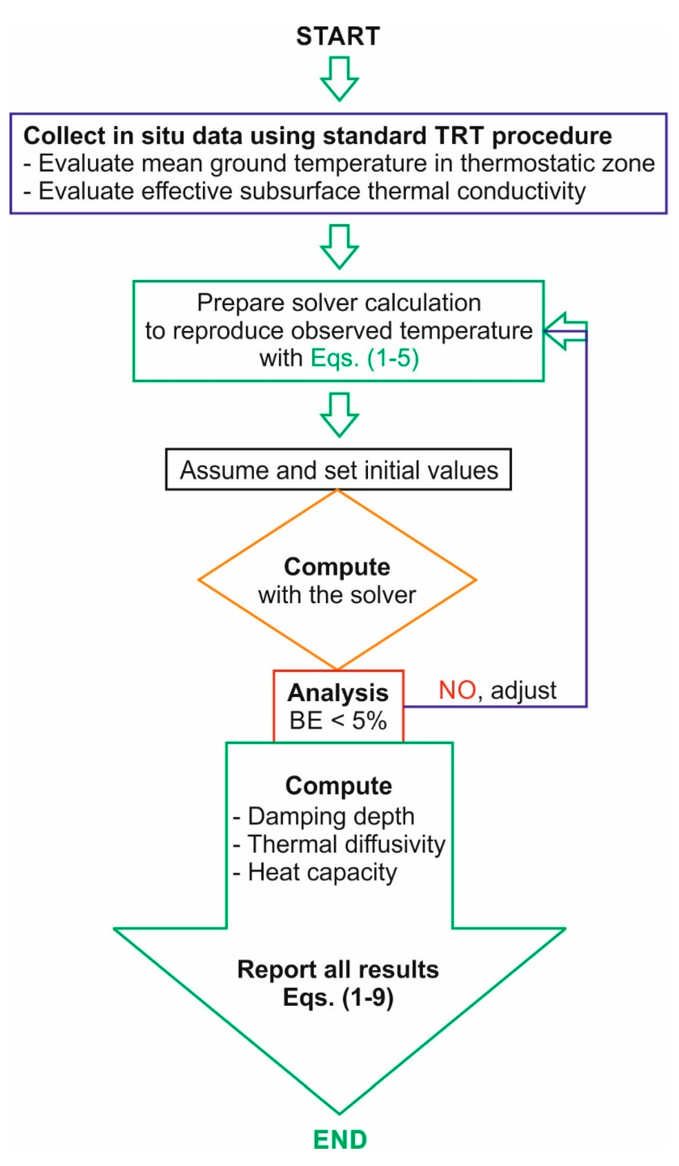
The following stepwise procedure (Figure 3) is suggested to summarize the parameter estimation analysis:
  • Accurately measure an equilibrium temperature profile (Tobs (z)) in a BHE and apply proper corrections for the rise of the water level in the U-pipe when using a wired probe as suggested by Pambou et al. [16];
  • Perform a standard TRT and evaluate in situ TC;
  • Prepare the solver optimization to reproduce the normalized temperature profile (Tg (z)) through Equations (1) to (5);
  • Match the observed and calculated temperature profile using Equation (2) and refine the results by minimizing BE (Equation (4)), which describes the difference between TUGT and C1;
  • Evaluate the quality of parameter estimation using statistical analysis (Equations (8) and (9)) and proceed to the next step when the results are within the best value range and thus considered acceptable by statical analysis (Equations (8) and (9));
  • Calculate the damping depth Zdd, in situ TD and HC (Equations (5)–(7)).
Microsoft Excel spreadsheet and its solver were used in this research to implement the equations, find the empirical coefficients by optimization and use the newly proposed method. The validation of the methodology is given in the next subsection.

2.5. Validation of the Proposed Method

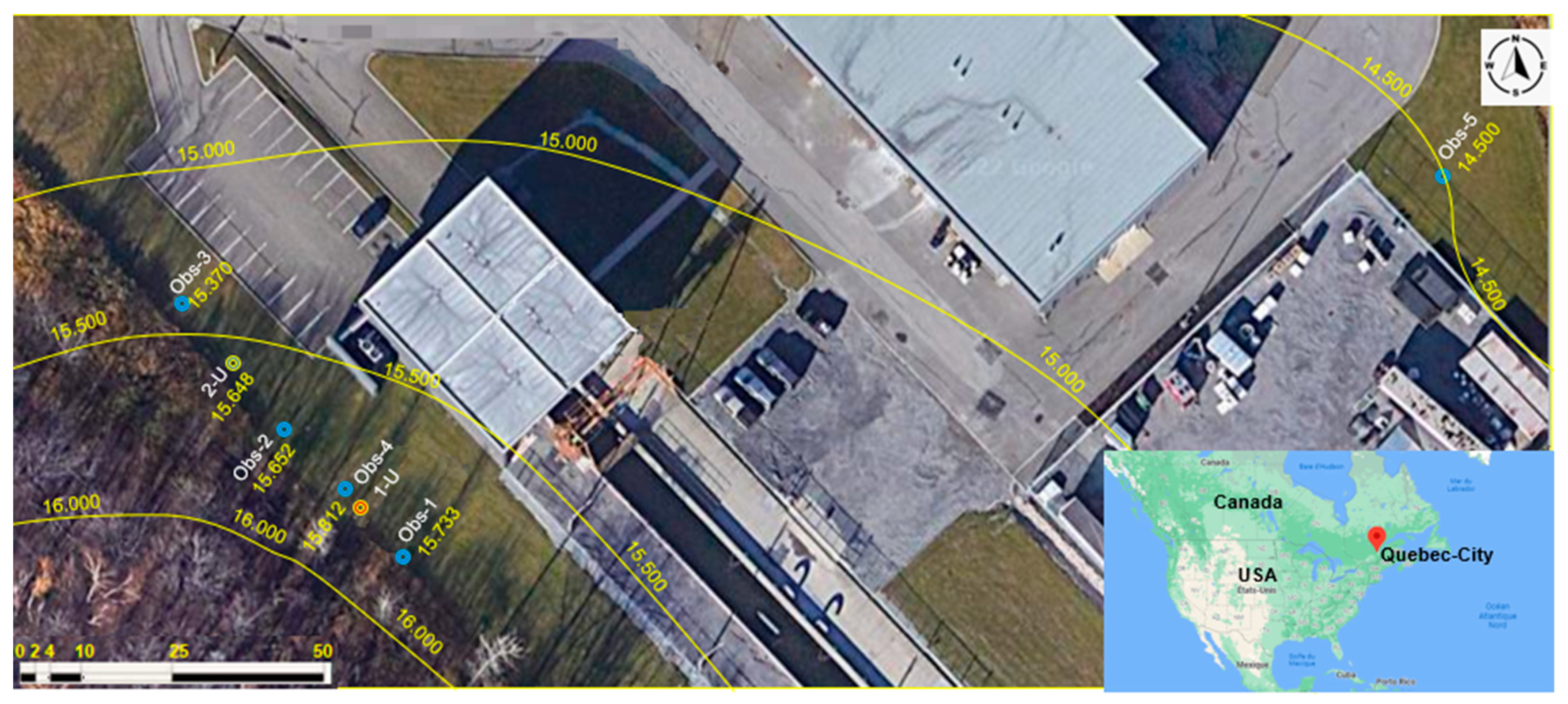
The methodology proposed in this study was verified and validated by evaluating the in situ HC at the INRS geothermal experimental site in Quebec City (Figure 4). This geothermal experimental site was chosen for its scientific and technical interest due to the availability of BHEs and observation wells. In fact, several studies have been conducted at this site to improve the design of the BHEs and the methods for characterization of thermal properties [4,9,11,20,21,40,41,42]. For example, field measurements were performed with different equipment to accurately assess TUGT [4,10,16] and several types of TRTs were carried out in different seasons (fall, winter, summer) to infer TC and borehole thermal resistance [4,10,11,16,33] (see Figure 5, for an example of field setup).
Recently, other research of interest was made to evaluate heat flux density [19], subsurface thermostratigraphic log and groundwater flow [16], as well as in situ HC evaluation by analytical equations and numerical modeling [11].

2.5.1. Borehole Heat Exchanger and Site Description

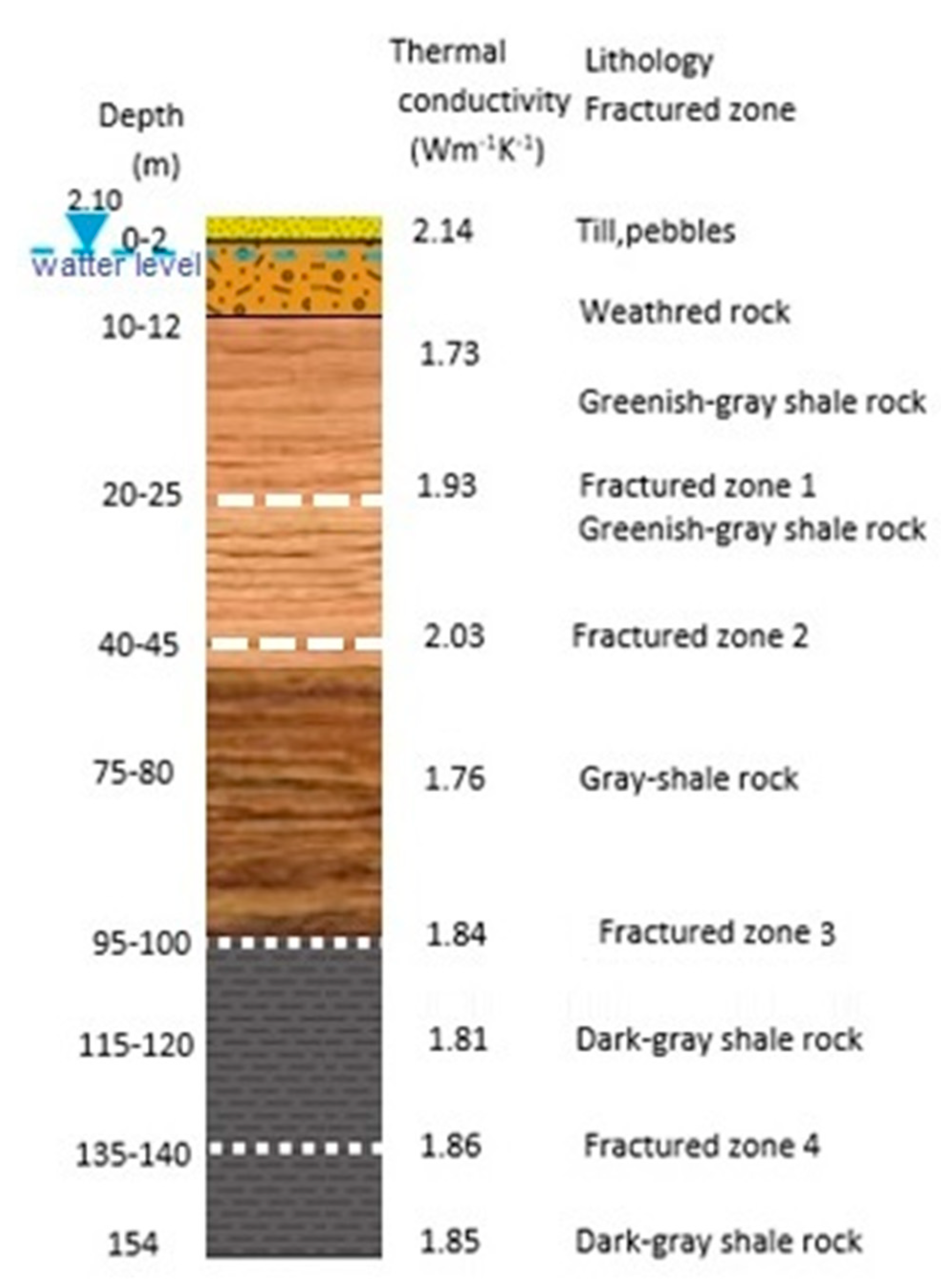
The INRS geothermal experimental site has two BHEs (1U-pipe and 2U-pipe) and five observation wells (Obs) that were installed from 2015 [10] to 2020 [11]. The single U-pipe BHE used in this study has a diameter of 114 mm (4.5 in) and is grouted with a mix of bentonite and silica sand down to the entire depth of 154 m. The subsurface described at the site of INRS consists of shale bedrock under an overburden of 10 to 14 m in thickness (see Figure 6, for the stratigraphy at the location of the 1U-BHE). The shale bedrock is fractured and groundwater fluxes were inferred in the fractured zones [10,16]. At the site, elevation of the water table varies from 14 to 16 m above sea level with northeast flow direction towards the Saint-Charles River.

2.5.2. Field Validation

Assessment of the mean TUGT is required to validate experimental coefficients C1 to C4 using the criterion described in the Equation (4). The first step involved estimating the mean TUGT from temperature profiles measured at equilibrium state. The ground temperature profiles were acquired in 2015 and 2016 before the TRTs, respectively [10,16,19]. Two techniques were used for the temperature measurements. One was based on a submersible wired probe using a vertical spatial resolution of 1 m. The second was based on a fiber optic distributed temperature sensor with a spatial resolution of 0.25 m [16,19]. The temperature measurements made with a wired probe were corrected for the rise of the water in the U-pipe of the BHE [16].
In the second step, the coefficients C3 and C4 were used to calculate the damping depth Zdd and effective in situ TD and HC. The bulk TC previously estimated from a conventional TRT performed at this field site [10] was used for the evaluation of HC.
Additionally, the in situ HC estimated with the approach developed in this work was consecutively compared to the results obtained for the in situ HC determined by Giordano et al. [11]. The approach developed by these authors to evaluate in situ HC is briefly described in the following lines to facilitate understanding and comparison.
Giordano et al. [11], at first, evaluated HC following the dual needle probe concept suggested in Raymond [4], using the 1-U BHE and the observation well (obs4; Figure 4). This allowed to independently assess the in situ HC and validate the OTRT method. The TRT was performed with a heating cable and temperature sensors in both the BHE and the observation well located 1.2 m apart. Temperature sensors were placed in the observation well at vertical distances varying from 2.5 to 5 m. The analysis was performed with the infinite line source equation and results from this test can be assumed as the most reliable field assessment of the in situ HC. As a second step, Giordano et al. [11] performed a sinusoidal heat injection for the OTRT based on Oberdorfer protocol [12]. The oscillatory thermal response was analyzed with equations proposed by Eskilson [44]. In situ TC was inferred using the infinite line source equation applied to the linear temperature component as in a conventional TRT [2,4,10,16]. Then, in situ TD was calculated using the amplitude attenuation and the phase lag of the oscillatory component [20,21,22,23,24,27,28,29,30]. HC was then evaluated similarly to what was done in this article using Equation (7).

3. Results

The validity and applicability of the new heat tracing method presented in this work to assess the in situ HC are presented and discussed below. A comparison between calculated and observed temperature was carried out, as well as between inferred thermal properties using results from various field methods applied at the same experimental site and previous geological characterization [10,11,16,18,19,45,46].

3.1. Estimation of Empirical Parameters

3.1.1. Observed Undisturbed Ground Temperature

Equilibrium ground temperature profiles (Tobs (z)) measured in warm and cold seasons were used to accurately analyze and evaluate the in situ TUTG (Figure 6). The evaluated TUTG was estimated to vary between 7.90 and 8.01 °C using temperature measurements from the depth interval 15 to 154 m and considering the temperature profiles measured at different times of the year with a vertical spatial resolution of 1 m (submersible sensor [10,16]) and 0.25 m (fiber optic [19]).
These profiles highlight the influence of the seasonal air temperature variations and the heat diffusion within the subsurface at the INRS experimental site. Two zones can be defined from the temperature profiles with analogy to Figure 1 and Figure 2. These two zones are: the upper part which is influenced by the surface conditions (thermocline zone) and the lower part which is not affected by seasonal variations (thermostatic zone) but the geothermal gradient, on the order of 12.00 °C km−1 (Figure 7; [19,34,46]). The temperature profiles acquired show an inverted gradient in the upper thermostatic zone (Figure 7). This inverted gradient can be due to recent climate warming [19,34,45,47]. Finally, it can be observed that in the thermostatic zone, both the temperature profile from the observation well and from the BHE have the same behavior. These results are in a good agreement with the assumption of temperature diffusion by heat conduction in a homogeneous and isotropic media [37,40,48,49].

3.1.2. Assessment of Empirical Coefficients

The TUTG was evaluated using a single equilibrium temperature profile (Tobs (z)) measured in 2015 before a conventional TRT was done (Figure 4 and Figure 7). The calculated TUTG, which is assumed equal to C1, gave the value 7.96 °C. The absolute difference between measured mean ground temperature (7.90–8.01 °C) and the calculated TUTG (or C1) ranges between 0.69% and 0.57%. Such results indicate a low bias error (Equation (4)). Furthermore, these results are used to validate the empirical coefficients C1 to C4 found by the solver (Equations (3) and (4); Table 1).
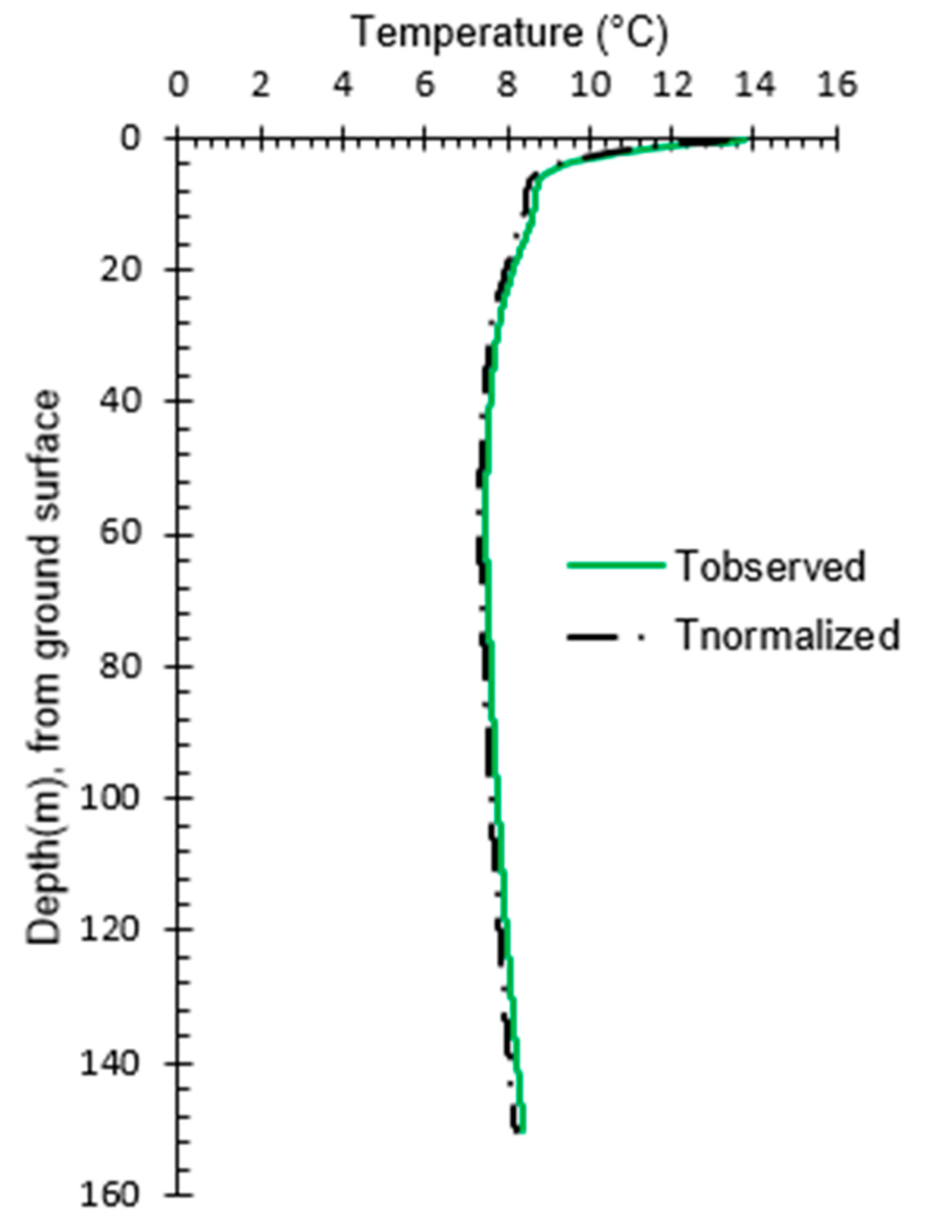
The results obtained suggest that calculated C1 is similar to TUTG evaluated from the measured temperature profile and is in the range of the validation criterion BE < 5%. Moreover, the value C2 equals to zero suggests that the calculated TUTG (or C1) is assessed close to the depth of zero temperature amplitude (Figure 1 and Figure 2). Thus, these experimental coefficients C3 and C4 can be used for the next step to ultimately evaluate the in situ HC (Figure 3). The curve-fit between normalized ground temperature profile (Tg (z)) based on Equation (1) against the measured temperature profile (Tobs (z)) at equilibrium state during the TRT [16,39] is plotted in Figure 8.

3.2. Subsurface Thermal Diffusivity and Volumetric Heat Capacity

3.2.1. Damping Depth (Zdd) and TD Estimation Using the New Empirical Method

The value of Zdd (Equation (3)) was evaluated equal to 2.70 m. Thus, the resulting subsurface TD (Equation (6)) was inferred to 7.28 × 10⁻⁷ m−2 s−1.

3.2.2. HC Estimation Using the New Empirical Method

The conventional TRT done on this BHE revealed a bulk TC of about 1.75 W m−1 K−1 [10]. Thus, the resulting subsurface HC (Equation (7)) is 2.40 MJ m−3 K−1 (Table 2) when considering the above TD.

3.2.3. Comparison of Calculated Subsurface Heat Capacity with the Dual Needle Concept

Temperature measurements taken at a depth of about 22 m in the observation well obs4 (Figure 4) with the heating cable TRT were used to evaluate both in situ TD and HC [11]. The results, which are thought most accurate among Giordano field method [11], are presented for each submersible temperature sensor inserted at different depths in the BHE and ground layer encountered in the observation well obs4 (Table 3).
Field results from dual needle concept were compared with those from this new heat tracing method using Equations (6) and (7) to infer the in situ HC (Table 2 and Table 3). The average absolute discrepancy for the upper layer made of mixed unconsolidated sedimentary deposits and weathered shale (0 to 12.50 m) was 13.01%, while that for the lower layer made of shale (17 m to 22 m) was 4.48% (Table 3). The average absolute discrepancy considering both layers was 10.16% (Table 3; Figure 5). This difference between field results obtained at the same site using different methods was considered small enough, and therefore, this new heat tracing method was confirmed reliable (Table 3).

3.2.4. Comparison of Calculated Subsurface Heat Capacity with OTRT Method

Results from this new heating tracing method were also compared with results from the OTRT method of Giordano et al. [11] (Table 4). Absolute discrepancy when considering the HC evaluated with the oscillatory resistance method and phase shift method was found to be greater than 26% compared with this new empirical approach (Table 2 versus Table 4).
The results obtained from the recovery period revealed an underestimated value on the order of 10%; while the difference with the oscillatory resistance analysis and from the phase shift analysis are out of 15%, respectively (Table 2 versus Table 4). The differences found in these values suggest that the OTRT may be affected by uncertainties, and it may be useful to use corrected factors to adjust the range of the values when evaluating in situ HC using the OTRT (Table 4). The sources for such variability can be caused by, for instance, the HC of the grout filling the BHE [11].
Despite some sources of uncertainty that need to be addressed, such as the influence of the backfilling material, the project made by Giordano et al. [11] proposed alternative avenues to improve in situ assessment of subsurface HC. Analysis of results reveals that the concept used by Giordano et al. [11] is straightforward but the implementation in the field of a sinusoidal heat injection can be complex and need specific analytical expertise, which is not always available. Finally, these results suggest that the new heat tracing method here developed and discussed below is, at present, more reliable than the OTRT and simpler than conducting a TRT with the dual probe concept requiring an observation well (Table 2, Table 3 and Table 4).

4. Discussion and Conclusions

A novel one-dimensional heat tracing field method was developed and applied to accurately evaluate the undisturbed ground temperature (TUGT = C1) and the damping depth (Zdd) of the surface temperature changes in the subsurface at the vicinity of the BHE. These values were used to infer the in situ TD (αcalc) and, subsequently, the in situ HC. The results were compared with other field methods undertaken at the same site. This comparison suggests that using this new empirical method in combination with the conventional TRT to assess TC can reduce uncertainty when characterizing heat storage properties. In other words, TUGT and effective subsurface TD and HC can now be inferred with the new approach in the scope of a TRT over the geological materials intercepted by a BHE.
This empirical heat tracing method assumes transient heat conduction mechanism of the surface temperature variations diffusing through an isotropic and homogeneous semi-infinite medium (i.e., the subsurface in which an equilibrium temperature profile is measured). This newly proposed method uses least squares and a nonlinear solver optimization to fit the observed temperature profile and to find the experimental coefficients (C1 to C4). These parameters are incorporated in the new semi-analytical ground temperature sinusoidal function which is assumed to be an upper boundary condition of the heat conduction equation [46,50,51]. This method thus relies on an accurate equilibrium ground temperature profile measured in a BHE before a TRT [10,17]. The calculated experimental coefficients are used to evaluate a damping depth and an effective TD. The bulk HC of the geological materials is afterwards estimated using a bulk in situ TC inferred from a conventional TRT. Evaluation of TC was made in the article with the infinite line source equation but could be made with a numerical approach as suggested by other authors [1,4,18,30,32]. This can help to better evaluate TC but will not significantly change the assessment of TD and HC, mostly relying on the determination of the empirical coefficients from an undisturbed temperature profile, in this newly proposed heat tracing approach.
The in situ HC evaluated with the newly proposed method at the INRS experimental site in Quebec City was successfully compared to that inferred by other field methods (Table 3 and Table 4) as a criterion of validation [11,51]. Furthermore, these results were in the range of thermal properties for geological materials of the Quebec City area [46]. Hence, the obtained results validate the model assumptions and the parameter estimation procedure. Consequently, the stepwise implementation of this new method (Figure 3) can be conducted in the scope of ground-coupled heat pump system design [1,3,4,10,11,19]. Moreover, this method proposes a new damping depth equation which does not rely on the temperature amplitude as the previous methods adopted to evaluate the in situ TD [20,21,22,23,24,27,28,29,30]. In addition, the newly proposed heat tracing method does not rely either on prior knowledge of the subsurface heat flux [18,19,51] or does not require time series of the annual temperature monitoring [9,14,20,21,22,23,24,25,26,27,28,29,30]. This is an advantage compared to previous damping depth methods used for the same purpose [34,35]. Field measurements only require a single temperature profile that can be rapidly collected before a conventional TRT. This highlights the advantages and novelty of the proposed methodology when compared to the sampling steps required by other approaches using time series of ground temperature measurements [20,21,22,23,24,27,28,29,30,45,52,53]. Another field benefit is that the new method does not need an additional borehole when compared to the dual probe method experimented in the field at the scale of a BHE by Giordano et al. [11]. A practical advantage is also related to the mathematical formulation that can be easily implemented and optimized with a built-in solver found in a spreadsheet program. Considering one hour for the field setup and measurements with a wireline temperature probe for a BHE of 154 m depth and a single analysis that should not require more than half an hour for data processing, the method can be qualified as fast when compared against commonly used field and laboratory methods [4,11,18].
Moreover, results obtained using this newly proposed heat tracing method depend on experimental coefficients that, in turn, rely on an accurate ground temperature profile measurement that was successfully reproduced at the INRS experimental site. Current practice is to infer the mean ground temperature from the measurements of a ground temperature profile that is acquired before a TRT and by lowering a submersible temperature datalogger in the BHE [10,16,18]. In some cases, measurements can be done with a 1 m spatial resolution over the length of the BHE that can reach 160 to 200 m. Measurements using a spatial resolution of 5 to 10 m are typically not good enough for this proposed method. Moreover, care should be taken with the field procedure by selecting an accurate temperature probe and by correcting the temperature profile for the water level rise when measured in a U-pipe [16]. For example, the submersible temperature sensor and pressure probe used in this study had a ±2 × 10⁻³ °C accuracy, <5 × 10⁻⁵ °C resolution, ±5 × 10⁻⁴ dbar accuracy and <1 × 10⁻⁵ dbar resolution.
It is worth highlighting that these results are obtained with the assumption of conductive heat transfer in a homogeneous and isotropic subsurface. However, a validation process through field-testing complemented by numerical modeling is recommended in case of a strongly heterogeneous and anisotropic subsurface or the presence of significant groundwater flow [3,14,22,48,53,54].
As scientific contributions, this study puts forward a new damping depth equation and field estimation of TD and HC relying on a single measured equilibrium ground temperature profile. It confirms that ground temperature profiles measured in BHEs are an inexpensive source of data that can be analyzed to obtain more information on the subsurface thermophysical properties [4,9,11,14,15,16,17,18,19,20,21,22,23]. These contributions provide advantages for the design of ground-coupled heat pump systems by considering this heat tracing method as a complementary in situ tool for improving conventional TRTs [1,2,4].

Author Contributions

Conceptualization and methodology were developed by C.H.K.P. and discussed with N.G. and validated by J.R. Field investigations were made by C.H.K.P. with contribution of M.M.M. and supervision of J.R. All authors have participated for writing—review and editing, writing—original draft preparation and formal analysis data curation under supervision of J.R. J.R. provided funding acquisition and supervised all steps of this work. All authors have read and agreed to the published version of the manuscript.

Funding

This research was funded by the National Science and Engineering Research Council of Canada (NSERC) through a discovery grant of Professor Raymond J. and the APC was funded by the Institut National de la Recherche Scientifique (INRS) of Quebec.

Institutional Review Board Statement

Not applicable.

Informed Consent Statement

Not applicable.

Data Availability Statement

Data supporting reported results can be found by writing to the corresponding author: [email protected].

Acknowledgments

Colleagues at INRS that further helped with the work are acknowledged. In memory of Maria Isabel Vélez Márquez, who has always had a word and a smile and an availability for those who were at the crossroads of their path. We kindly recognize her contribution, involvement and listening ear during the primary discussions on the problems of this project and its scientific feasibility.

Conflicts of Interest

The authors declare no conflict of interest. The funders had no role in the design of the study; in the collection, analyses, or interpretation of data; in the writing of the manuscript, or in the decision to publish the results.

Abbreviations

Nomenclature
C1 to C4 empirical coefficient
eexponential
Llength (m)
Nnumber of observations
Pharmonic period for a radial frequency
SINsine function
Ttemperature (°C)
yassessed parameter
zdepth (m)
Zdamping depth (m)
Greek symbol
αthermal diffusivity (m2 s−1)
λthermal conductivity for injection period (W m−1 K−1)
πconstant (3.14159265358979)
Subscript
calccalculated
dddamping depth
effeffective
gnormalized
obsobserved
botbottom
Abbreviation
BHEborehole heat exchanger
Eqequation
HCvolumetric heat capacity
OTRToscillatory thermal response test
RErelative error
RMSErelative mean square error
SCnumerical simulation case
TCthermal conductivity
TDthermal diffusivity
TRTthermal response test
1-Usingle U-pipe
2-Udouble U-pipe
UGTundisturbed ground temperature

References

  1. Gehlin, S.E.A.; Spitler, J.D. Thermal response testing for ground source heat pump systems—An historical review. Renew. Sustain. Energy Rev. 2015, 50, 1125–1137. [Google Scholar]
  2. Sakata, Y.; Katsura, T.; Serageldin, A.A.; Nagano, K.; Ooe, M. Evaluating Variability of Ground Thermal Conductivity within a Steep Site by History Matching Underground Distributed Temperatures from Thermal Response Tests. Energies 2021, 14, 1872. [Google Scholar] [CrossRef]
  3. Antelmi, M.; Alberti, L.; Angelotti, A.; Curnis, S.; Zille, A.; Colombo, L. Thermal and hydrogeological aquifers characterization by coupling depth-resolved thermal response test with moving line source analysis. Energy Convers. Manag. 2020, 225, 113400. [Google Scholar] [CrossRef]
  4. Raymond, J. Assessment of the subsurface thermal conductivity for geothermal applications. Colloquium 2016 Manuscript. Rev. Can. De Géotechnique 2018, 9, 1209–1229. [Google Scholar] [CrossRef] [Green Version]
  5. Kluitenberg, G.J.; Das, B.S.; Bristow, K.L. Error analysis of the heat pulse method for measuring soil volumetric heat capacity, diffusivity, and conductivity. Soil. Sci. Soc. Am. J. 1995, 59, 719–726. [Google Scholar] [CrossRef]
  6. Miranda, M.M.; Giordano, N.; Raymond, J.; Pereira, A.J.S.C.; Dezayes, C. Thermophysical properties of surficial rocks: A tool to characterize geothermal resources of remote northern regions. Geotherm. Energy 2020, 8, 4. [Google Scholar] [CrossRef]
  7. Waples, D.W.; Waples, J.S. A review and evaluation of specific heat capacities of rocks, minerals, and subsurface fluids. Part 1: Minerals and nonporous rocks. Nat. Resour. Res. 2004, 13, 97–122. [Google Scholar] [CrossRef]
  8. Waples, D.W.; Waples, J.S. A review and evaluation of specific heat capacities of rocks, minerals, and subsurface fluids. Part 2: Fluids and porous rocks. Nat. Resour. Res. 2004, 13, 123–130. [Google Scholar] [CrossRef]
  9. Márquez, J.M.A.; Bohórquez, M.Á.M.; Melgar, S.G. Ground Thermal Diffusivity Calculation by Direct Soil Temperature Measurement. Application to very low enthalpy geothermal energy systems. Sensors 2016, 16, 306. [Google Scholar] [CrossRef] [Green Version]
  10. Raymond, J.; Ballard, J.-M.; Pambou, K.C.H. Field assessment of a ground heat exchanger performance with a reduced borehole diameter. In Proceedings of the 70th Canadian Geotechnical Conference and the 12th Joint CGS/IAH-CNC Groundwater Conference, Ottawa, ON, Canada, 4 October 2017. [Google Scholar]
  11. Giordano, N.; Lamarche, L.; Raymond, J. Evaluation of subsurface heat capacity through oscillatory thermal response tests. Energies 2021, 14, 5791. [Google Scholar] [CrossRef]
  12. Oberdorfer, P. Heat Transport Phenomena in Shallow Geothermal Boreholes—Development of a Numerical Model and a Novel Extension for the Thermal Response Test Method by Applying Oscillating Excitations. Ph.D. Thesis, Göttingen University, Göttingen, Germany, 2014. [Google Scholar]
  13. Javidan, M.; Asgari, M.; Gholinia, M.; Nozari, M.; Asgari, A.; Ganji, D.D. Thermal energy storage inside the chamber with a brick wall using the phase change process of paraffinic materials: A numerical simulation. Theor. Appl. Mech. Lett. 2022, 100329, in press. [Google Scholar] [CrossRef]
  14. Lehr, C.; Sass, I. Thermo-optical parameter acquisition and characterization of geologic properties: A 400-m deep BHE in a karstic alpine marble aquifer. Environ. Earth Sci. 2014, 72, 1403–1419. [Google Scholar] [CrossRef]
  15. Hakala, P.; Martinkauppi, A.; Martinkauppi, I. Evaluation of the Distributed Thermal Response Test (DTRT): Nupurinkartano as a case study. Rep. Investig. 2014, 211, 35. [Google Scholar]
  16. Pambou, K.C.H.; Raymond, J.; Lamarche, L. Improving thermal response tests with wireline temperature logs to evaluate ground thermal conductivity profiles and groundwater fluxes. Heat Mass Transf. 2019, 55, 1829–1843. [Google Scholar] [CrossRef]
  17. Gehlin, S.; and Nordell, B. Determining undisturbed ground temperature for thermal response test. ASHRAE Trans. 2003, 109, 151–156. [Google Scholar]
  18. Raymond, J.; Lamarche, L.; Malo, M. Extending thermal response test assessments with inverse numerical modeling of temperature profiles measured in ground heat exchangers. Renew. Energy 2016, 99, 614–621. [Google Scholar] [CrossRef]
  19. Márquez, M.I.V.; Raymond, J.; Blessent, D.; Philippe, M. Terrestrial heat flow evaluation from thermal response tests combined with temperature profiling. Phys. Chem. Earth Parts A/B/C 2019, 113, 22–30. [Google Scholar] [CrossRef]
  20. Kusuda, T.; Achenbach, P.R. Earth Temperature and Thermal Diffusivity at Selected Stations in United States. ASHRAE Trans. 1965, 71, 61–74. [Google Scholar]
  21. Horton, R.; Wierenga, P.J.; Nielsen, D.R. Evaluation of methods for determination the apparent thermal diffusivity of soil near the surface. Soil. Sci. Soc. Am. J. 1983, 47, 23–32. [Google Scholar] [CrossRef]
  22. Taniguchi, M. Evaluation of vertical groundwater fluxes and thermal properties of aquifers based on transient temperature-depth profiles. Water Resour. Res. 1993, 29, 2021–2026. [Google Scholar] [CrossRef]
  23. Adams, W.M.; Watts, G.; Masson, G. Estimation of thermal diffusivity from field observations of temperature as a function of time and deep. Am. Mineral. 1976, 61, 560–568. [Google Scholar]
  24. Costello, T.A. Apparent Thermal Diffusivity of Soil Determined by Analysis of Diurnal Temperatures (Fourier Series, Nonlinear Regression). Ph.D. Thesis, Louisiana State University and Agricultural and Mechanical College, Baton Rouge, LA, USA, 1986. [Google Scholar]
  25. Stallman, R.W. Steady one-dimensional fluid flow in a semi-infinite porous medium with sinusoidal surface temperature. J. Geophys. Res. 1965, 13, 2821–2827. [Google Scholar] [CrossRef]
  26. Williams, G.P.; Gold, L.W. CBD-180 Ground Temperatures. Natl. Res. Counc. Can. 1976, 100, 101. [Google Scholar]
  27. Tong, B.; Gao, Z.; Horton, R.; Wang, L. Soil Apparent Thermal Diffusivity Estimated by Conduction and by Conduction–Convection Heat Transfer Models. J. Hydrometeorol. 2017, 18, 109–118. [Google Scholar] [CrossRef] [Green Version]
  28. Xing, L.U. Estimations of Undisturbed Ground Temperatures Using Numerical and Analytical Modeling. Ph.D. Thesis, Oklahoma State University, Stillwater, OK, USA, 1 December 2014. [Google Scholar]
  29. Nassar, I.N.; Horton, R. Determination of soil apparent thermal diffusivity from multiharmonic temperature analysis for nonuniform soils. Soil. Sci. 1990, 149, 125–130. [Google Scholar] [CrossRef]
  30. Naranjo-Mendoza, C.; Wright, A.J.; Oyinlola, M.A.; Greenough, R.M. A comparison of analytical and numerical model predictions of shallow soil temperature variation with experimental measurements. Geothermics 2018, 76, 38–49. [Google Scholar] [CrossRef]
  31. Cui, W.; Liao, Q.; Chang, G.; Chen, G.; Peng, Q.; Jen, T.C. Measurement, and prediction of undisturbed underground temperature distribution. ASME Int. Mech. Eng. Congr. Expo. 2011, 54907, 671–676. [Google Scholar]
  32. Cho, S.W.; Ihm, P. Development of a Simplified Regression Equation for Predicting Underground Temperature Distributions in Korea. Energies 2018, 11, 2894. [Google Scholar] [CrossRef] [Green Version]
  33. Márquez, M.I.V.; Raymond, J.; Blessent, D.; Philippe, M.; Simon, N.; Bour, O.; Lamarche, L. Distributed Thermal Response Tests Using a Heating Cable and Fiber Optic Temperature Sensing. Energies 2018, 11, 3059. [Google Scholar] [CrossRef] [Green Version]
  34. Badache, M.; Eslami-Nejad, P.; Ouzzane, M.; Aidoun, Z. A new modeling approach for improved ground temperature profile determination. Renew. Energy 2016, 85, 436–444. [Google Scholar] [CrossRef]
  35. IEA ECES ANNEX 21 Thermal Response Test (TRT) Final Report. 2013. Available online: http://media.geoenergicentrum.se/2017/11/IEA_ECES_2013_Annex21_FinalReport.pdf (accessed on 3 August 2015).
  36. Franco, A.; Conti, P. Clearing a path for ground heat exchange systems: A review on thermal response test (TRT) methods and a geotechnical routine test for estimating soil thermal properties. Energies 2020, 11, 2965. [Google Scholar] [CrossRef]
  37. Holmes, T.R.H.; Owe, M.; De Jeu, R.A.M.; Kooi, H. Estimating the soil temperature profile from a single depth observation. British Society of Soil Science. Eur. J. Soil Sci. Water Resour. Res. 2008, 44, 9. [Google Scholar]
  38. Droulia, F.; Lykoudis, S.; Tsiros, I.; Alvertos, N.; Akylas, E.; Garofalakis, I. Ground temperature estimations using simplified analytical and semi-empirical approaches. Sol. Energy 2009, 83, 211–219. [Google Scholar] [CrossRef]
  39. Adeniyi, M.O.; Oshunsanya, S.O.; Nymphas, E.F. Validation of analytical algorithms for the estimation of soil thermal properties using de Vries model. Am. J. Sci. Ind. Res. 2012, 3, 103–114. [Google Scholar] [CrossRef]
  40. Gwadera, M.; Larwa, B.; Kupiec, K. Undisturbed ground temperature—Different methods of determination. Sustainability 2017, 9, 2055. [Google Scholar] [CrossRef] [Green Version]
  41. Wang, J.; Lee, W.F.; Ling, P.P. Estimation of Thermal Diffusivity for Greenhouse Soil Temperature Simulation. Appl. Sci. 2020, 10, 653. [Google Scholar] [CrossRef] [Green Version]
  42. Eskilson, P. Thermal Analysis of Heat Extraction Boreholes. Ph.D. Thesis, University of Lund, Lund, Sweden, 1987. [Google Scholar]
  43. Carslaw, H.S.; Jaeger, J.C. Conduction of Heat in Solids; Oxford University Press: Oxford, UK, 1947. [Google Scholar]
  44. Holzbecher, E. Inversion of temperature time series from near-surface porous sediments. J. Geophys. Eng. 2005, 2, 343–348. [Google Scholar] [CrossRef]
  45. Lamarche, L.; Raymond, J.; Pambou, K.H.C. Evaluation of the Internal and Borehole Resistances during Thermal Response Tests and Impact on Ground Heat Exchanger Design. Energies 2018, 11, 38. [Google Scholar] [CrossRef] [Green Version]
  46. Raymond, J.; Bédard, K.; Comeau, F.A.; Gloaguen, E.; Comeau, G.; Millet, E.; Foy, S. A workflow for bedrock thermal conductivity map to help designing geothermal heat pump systems in the St. Lawrence Lowlands, Québec, Canada. Sci. Technol. Built Environ. 2019, 25, 963–979. [Google Scholar] [CrossRef]
  47. Chouinard, C. Reconstitutions des Températures de Surface au Canada: Des Températures Basales du Glacier Laurentidien Aux Changements Récents du Climat Arctique. Ph.D. Thesis, Université du Québec à Montréal (UQAM), Montreal, QC, Canada, 2008. [Google Scholar]
  48. Wagner, R.; Clauser, C. Evaluating thermal response tests using parameter estimation for thermal conductivity and thermal capacity. J. Geophys. Eng. 2005, 2, 349–356. [Google Scholar] [CrossRef]
  49. Radioti, G.; Sartor, K.; Charlier, R.; Dewallef, P.; Nguyen, F. Effect of undisturbed ground temperature on the design of closed-loop geothermal systems: A case study in a semi-urban environment. Appl. Energy 2017, 200, 89–105. [Google Scholar] [CrossRef]
  50. Dec, D.; Dörner, J.; Horn, R. Effect of soil management on their thermal properties. J. Soil. Sci. Plant Nutr. 2009, 9, 26–39. [Google Scholar] [CrossRef]
  51. Miranda, M.A.; Marquez, V.M.I.; Raymond, J.; Dezayes, C. A numerical approach to infer terrestrial heat flux from shallow temperature profiles in remote northern regions. Geothermics 2021, 93, 102064. [Google Scholar] [CrossRef]
  52. Zschocke, A. Correction of non-equilibrated temperature logs and implications for geothermal investigations. J. Geophys. Eng. 2005, 2, 364–371. [Google Scholar] [CrossRef]
  53. Verdoya, M.; Chiozzi, P.; Pasquale, V. Thermal log analysis for recognition of ground surface temperature change and water movements. Clim. Past 2007, 3, 315–324. [Google Scholar] [CrossRef] [Green Version]
  54. Antelmi, M.; Alberti, L.; Barbieri, S.; Panday, S. Simulation of thermal perturbation in groundwater caused by Borehole Heat Exchangers using an adapted CLN package of MODFLOW-USG. J. Hydrol. 2021, 596, 126106. [Google Scholar] [CrossRef]
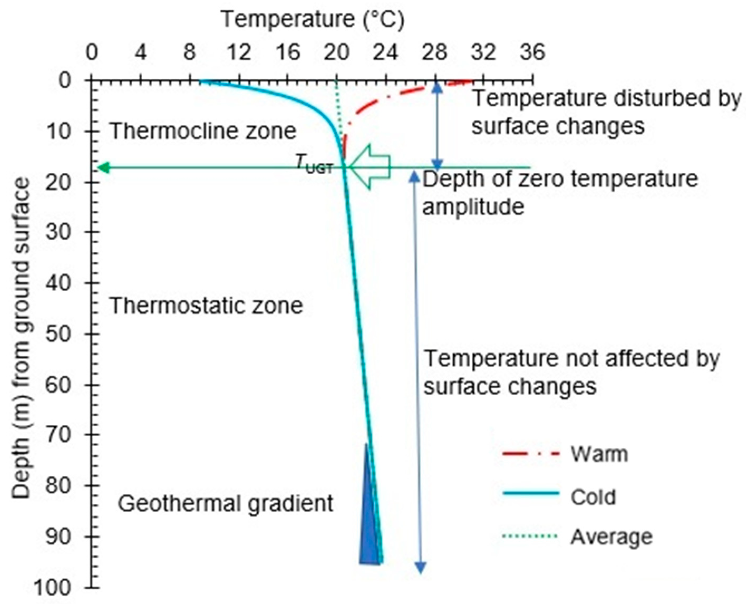
Figure 1. Theoretical ground temperature distribution showing the depth of zero temperature amplitude. The blue triangle indicates the geothermal gradient.
Geosciences 12 00180 g001
Figure 2. Ground temperature distribution showing the damping depth and the depth of zero temperature amplitude, with (a) annual ground temperature profile span and (b) components of the daily oscillatory ground temperature influenced by surface temperature variations diffusing in the shallow subsurface.
Geosciences 12 00180 g002
Figure 3. Procedure for assessing the in situ HC from a temperature profile undisturbed by a TRT and the in situ TC inferred from the TRT.
Geosciences 12 00180 g003
Figure 4. Geothermal experimental site at INRS (Quebec City). Numbers beside boreholes (obs and U) and along yellow lines indicate elevation of the water table in meters above the sea level and local potentiometric level, respectively See field set up in [11]. Obs are four open observation wells, while 1-Uand 2-U are the borehole heat exchangers.
Geosciences 12 00180 g004
Figure 5. (a) Field equipment for ground temperature profile measurement at INRS geothermal experimental site (Quebec), with examples of (b) how to conduct measurements in the single U-pipe BHE and (c) results of observed ground temperature profiling; (2) and (3) are uncorrected for water level rise in the 1-U pipe, while (1) is corrected, respectively (see field protocol in Pambou et al. [16]).
Geosciences 12 00180 g005
Figure 6. Thermostratigraphic log of the 1UBHE at the INRS experimental site, with layered TC from Pambou et al. [19] and geological cross-correlation based on borehole logs from Raymond et al. [10].
Geosciences 12 00180 g006
Figure 7. Observed undisturbed ground temperatures at the INRS experimental site.
Geosciences 12 00180 g007
Figure 8. Normalized (Tnormalized) and measured (Tobserved) temperature profiles at the INRS experimental site.
Geosciences 12 00180 g008
Table 1. Experimental coefficients estimated from solver optimization (Equations (2)–(4)) applied on the temperature profile measured (Tobs (z)) in 2015 at the INRS experimental site before a TRT.
Empirical CoefficientValue
C1 (°C)7.96
C2 (°C)0
C3 (m)0.30
C4 (m)2.52
Table 2. In situ TD and HC estimated (Equations (2)–(6)) by applying the new heat tracing method on the temperature profile measured in 2015 at the INRS experimental site before a TRT.
ParameterValueDescription
C1 (°C)7.96Undisturbed ground temperature
Zdd (m)2.70Damping depth
αcalc (m−2 s−1)7.28 × 10⁻⁷Thermal diffusivity
HCcalc (MJ m−3 K−1)2.40Volumetric heat capacity
Table 3. Subsurface HC inferred with the new empirical method compared to the results obtained by [11] using the dual needle concept at the INRS experimental site. Mean values of each method and mean relative difference in bold.
Depth
(m)
TRT with Observation Well HC
(MJ m−3 K−1)
New Empirical
Approach HC
(MJ m−3 K−1)
Relative
Difference
(%)
Thermo-Geological Zone
52.812.4014.59Overburden
(sediments)
7.502.6710.11
102.8114.59
12.502.7512.73
172.27−5.73Bedrock
(shale)
222.483.23
Mean2.612.40 10.16
Table 4. Subsurface HC inferred with the new empirical method compared to the results obtained by [11] using the OTRT method at the INRS experimental site.
Analysis ProcedureOTRT HC
(MJ m−3 K−1)
New Empirical
Approach HC
(MJ m−3 K−1)
Relative
Difference
(%)
Thermal recovery period2.162.40−11.11
Oscillatory resistance1.90−26.32
Phase shift3.5632.58
Publisher’s Note: MDPI stays neutral with regard to jurisdictional claims in published maps and institutional affiliations.