
Nature of Ore Fluid at the Sopokomil Zn-Pb Deposit, North Sumatra, Indonesia: Implications for Metal Transport and Sulfide Deposition


Abstract
1. Introduction

2. Geologic Background
2.1. Regional and Local Geology
2.2. Mineralization
3. Methods
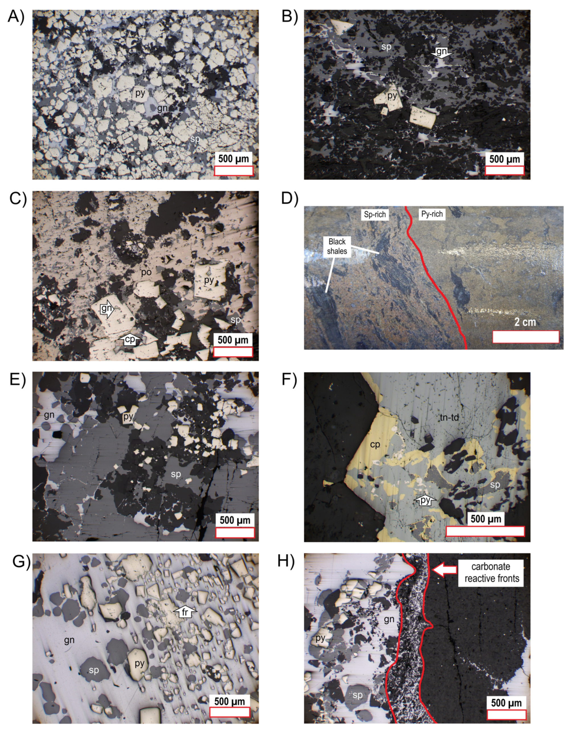
3.1. Ore Mineralogy
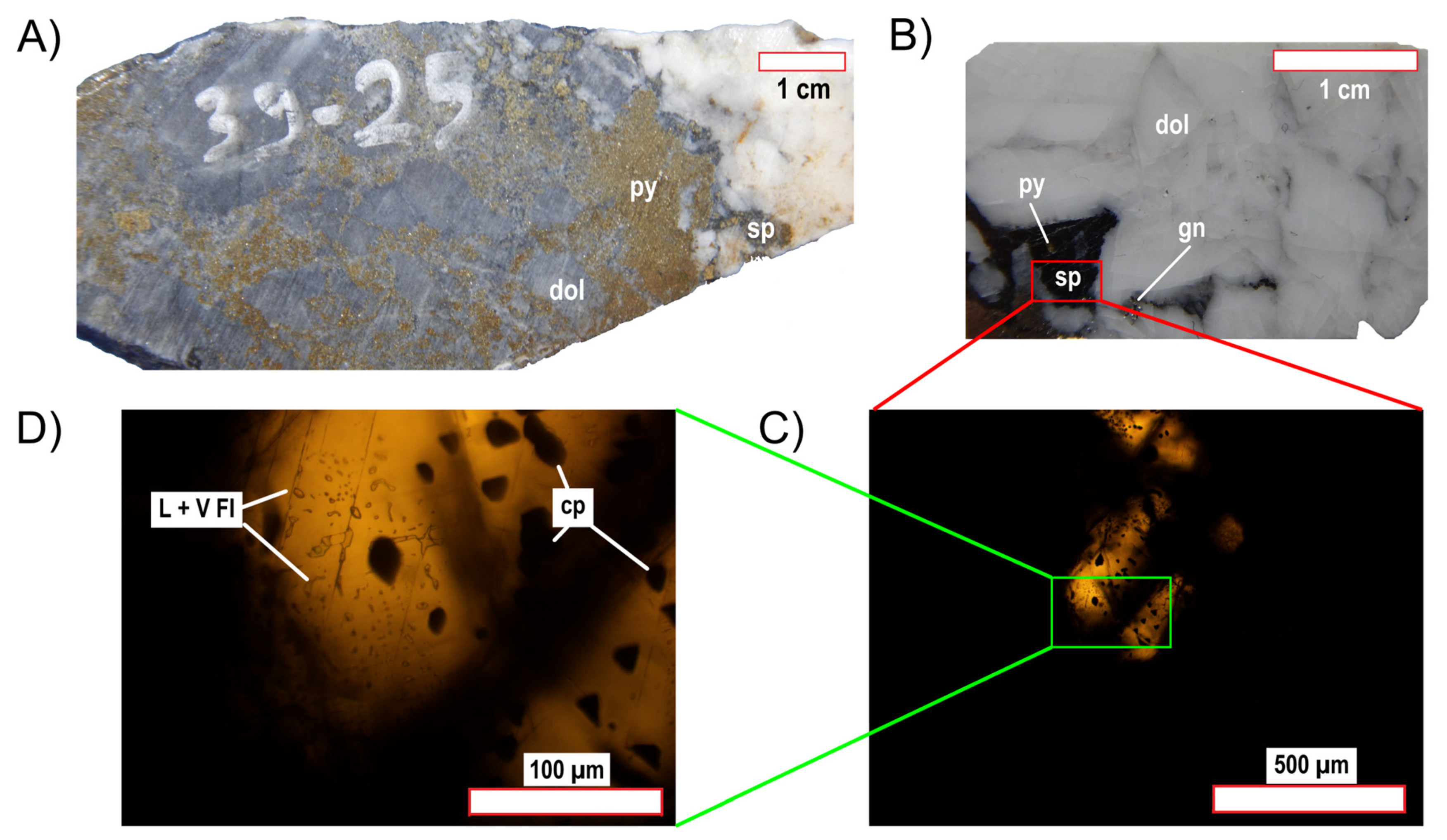
3.2. Fluid Inclusion Microthermometry
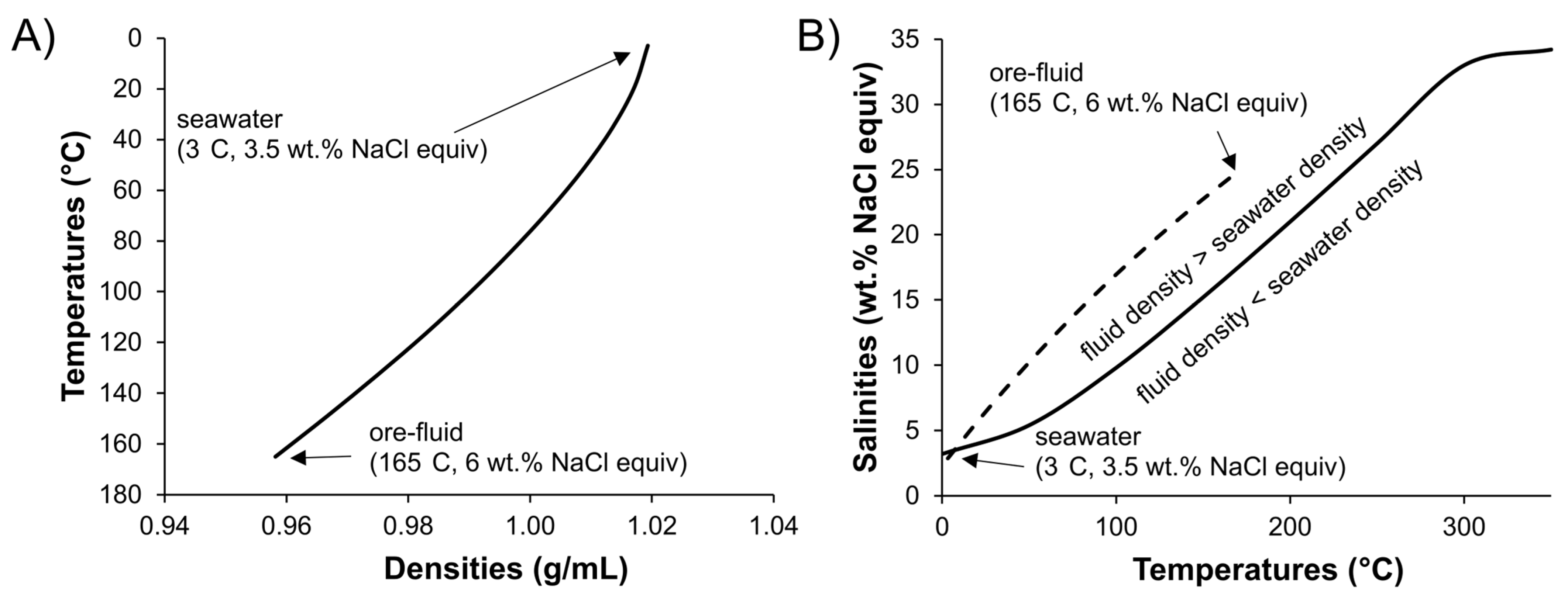
3.3. Density Modeling
3.4. EPMA
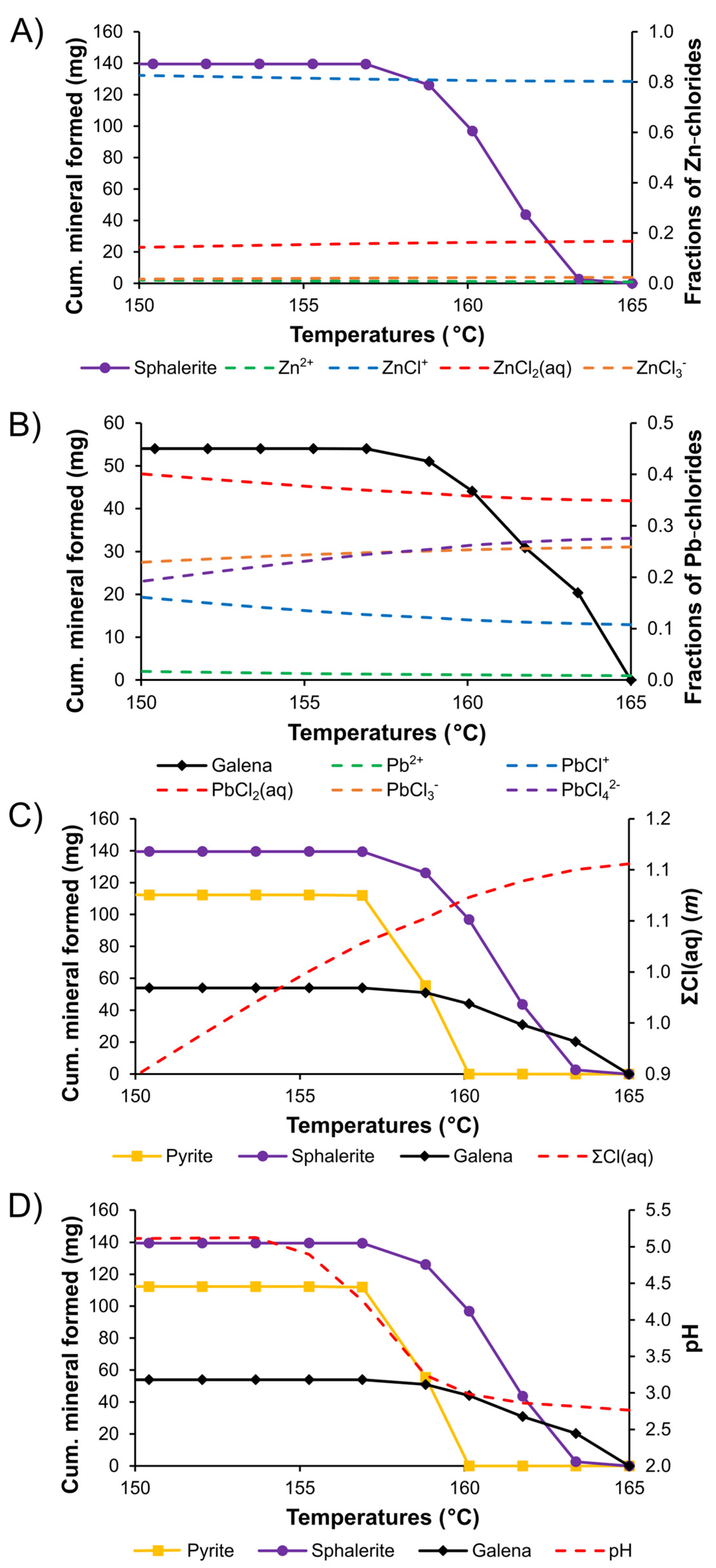
3.5. Thermodynamic Modelling
4. Results
4.1. Sample Mineralogy
4.2. Fluid Inclusion Microthermometry
4.3. Sphalerite Composition
5. Discussion
5.1. Ore-Fluid Temperatures, Salinities, and Densities
5.2. Ore-Fluid Redox State and pH
5.3. Metal Transport and Sulfide Deposition
5.4. Genetic Model
6. Conclusions
Author Contributions
Funding
Institutional Review Board Statement
Informed Consent Statement
Data Availability Statement
Acknowledgments
Conflicts of Interest
Appendix A

| Initial Ore Fluid | Marine Sediment Porewater | ||
|---|---|---|---|
| ΣC | (m) | 0.256 | 0.002331235 |
| ΣCa | (m) | 0.031205 | 0.010255003 |
| ΣCl | (m) | 1.10103 | 0.54720335 |
| ΣFe | (m) | 0.001 | 6.09 × 10⁻⁸ |
| ΣH | (m) | 111.02555 | 109.1324 |
| ΣK | (m) | 0.093614 | 0.010026011 |
| ΣMg | (m) | 3.12 × 10⁻⁵ | 0.053075498 |
| ΣNa | (m) | 0.936142 | 0.46977356 |
| ΣO | (m) | 55.508373 | 55.189569 |
| ΣPb | (m) | 0.000241313 | 1.45 × 10¹⁰ |
| ΣS | (m) | 0.001 | 0.028190974 |
| ΣZn | (m) | 0.00153 | 7.65 × 10⁻⁸ |
| Run | 1 | 2 | 3 | 4 | 5 | 6 | 7 | 8 | 9 | 10 | 11 | |
|---|---|---|---|---|---|---|---|---|---|---|---|---|
| Input | ||||||||||||
| Porewater /ore fluid | (kg/kg) | 0.00 | 0.01 | 0.02 | 0.03 | 0.04 | 0.05 | 0.06 | 0.07 | 0.08 | 0.09 | 0.10 |
| Ore fluid | (kg) | 1.00 | 1.00 | 1.01 | 1.03 | 1.06 | 1.10 | 1.16 | 1.23 | 1.31 | 1.42 | 1.55 |
| Porewater | (kg) | 0.00 | 0.01 | 0.02 | 0.03 | 0.04 | 0.06 | 0.07 | 0.09 | 0.11 | 0.13 | 0.15 |
| T | (°C) | 165 | 163 | 162 | 160 | 159 | 157 | 155 | 154 | 152 | 150 | 149 |
| P | (bar) | 250 | 250 | 250 | 250 | 250 | 250 | 250 | 250 | 250 | 250 | 250 |
| Output | ||||||||||||
| Aqueous phase | (kg) | 1.00 | 1.01 | 1.03 | 1.06 | 1.10 | 1.16 | 1.23 | 1.31 | 1.42 | 1.55 | 1.70 |
| Ca2+ | (m) | 2.2 × 10⁻² | 2.2 × 10⁻² | 2.1 × 10⁻² | 2.1 × 10⁻² | 2.1 × 10⁻² | 2.0 × 10⁻² | 2.0 × 10⁻² | 1.9 × 10⁻² | 1.8 × 10⁻² | 1.6 × 10⁻² | 1.5 × 10⁻² |
| CaCl+ | (m) | 9.2 × 10⁻³ | 8.9 × 10⁻³ | 8.6 × 10⁻³ | 8.3 × 10⁻³ | 7.9 × 10⁻³ | 7.4 × 10⁻³ | 6.9 × 10⁻³ | 6.4 × 10⁻³ | 5.7 × 10⁻³ | 5.0 × 10⁻³ | 4.4 × 10⁻³ |
| CaCl2 | (m) | 6.6 × 10⁻⁴ | 6.4 × 10⁻⁴ | 6.1 × 10⁻⁴ | 5.8 × 10⁻⁴ | 5.4 × 10⁻⁴ | 5.0 × 10⁻⁴ | 4.6 × 10⁻⁴ | 4.1 × 10⁻⁴ | 3.6 × 10⁻⁴ | 3.1 × 10⁻⁴ | 2.6 × 10⁻⁴ |
| Fe2+ | (m) | 7.5 × 10⁻⁴ | 7.5 × 10⁻⁴ | 7.4 × 10⁻⁴ | 7.2 × 10⁻⁴ | 3.5 × 10⁻⁴ | 1.8 × 10⁻⁶ | 2.4 × 10⁻⁸ | 3.2 × 10⁻⁹ | 1.5 × 10⁻⁹ | 7.4 × 10⁻¹⁰ | 3.5 × 10⁻¹⁰ |
| FeCl+ | (m) | 2.5 × 10⁻⁴ | 2.5 × 10⁻⁴ | 2.4 × 10⁻⁴ | 2.3 × 10⁻⁴ | 1.1 × 10⁻⁴ | 5.4 × 10⁻⁷ | 6.8 × 10⁻⁹ | 8.9 × 10⁻¹⁰ | 3.9 × 10⁻¹⁰ | 1.9 × 10⁻¹⁰ | 8.5 × 10⁻¹¹ |
| FeCl2 | (m) | 4.0 × 10⁻⁷ | 3.5 × 10⁻⁷ | 3.0 × 10⁻⁷ | 2.5 × 10⁻⁷ | 1.0 × 10⁻⁷ | 4.6 × 10⁻¹⁰ | 5.0 × 10⁻¹² | 5.7 × 10⁻¹³ | 2.2 × 10⁻¹³ | 9.1 × 10⁻¹⁴ | 3.6 × 10⁻¹⁴ |
| K+ | (m) | 9.2 × 10⁻² | 9.2 × 10⁻² | 9.0 × 10⁻² | 8.8 × 10⁻² | 8.5 × 10⁻² | 8.1 × 10⁻² | 7.7 × 10⁻² | 7.2 × 10⁻² | 6.8 × 10⁻² | 6.3 × 10⁻² | 5.8 × 10⁻² |
| KCl | (m) | 1.7 × 10⁻³ | 1.6 × 10⁻³ | 1.6 × 10⁻³ | 1.5 × 10⁻³ | 1.3 × 10⁻³ | 1.2 × 10⁻³ | 1.1 × 10⁻³ | 1.0 × 10⁻³ | 8.9 × 10⁻⁴ | 7.8 × 10⁻⁴ | 6.8 × 10⁻⁴ |
| Mg2+ | (m) | 2.4 × 10⁻⁵ | 4.5 × 10⁻⁴ | 1.3 × 10⁻³ | 2.5 × 10⁻³ | 4.1 × 10⁻³ | 6.1 × 10⁻³ | 8.3 × 10⁻³ | 1.1 × 10⁻² | 1.2 × 10⁻² | 1.4 × 10⁻² | 1.6 × 10⁻² |
| MgCl+ | (m) | 7.0 × 10⁻⁶ | 1.3 × 10⁻⁴ | 3.6 × 10⁻⁴ | 6.8 × 10⁻⁴ | 1.1 × 10⁻³ | 1.5 × 10⁻³ | 2.0 × 10⁻³ | 2.5 × 10⁻³ | 2.8 × 10⁻³ | 3.1 × 10⁻³ | 3.4 × 10⁻³ |
| Na+ | (m) | 7.9 × 10⁻¹ | 7.9 × 10⁻¹ | 7.9 × 10⁻¹ | 7.8 × 10⁻¹ | 7.7 × 10⁻¹ | 7.5 × 10⁻¹ | 7.4 × 10⁻¹ | 7.2 × 10⁻¹ | 7.0 × 10⁻¹ | 6.8 × 10⁻¹ | 6.6 × 10⁻¹ |
| NaCl | (m) | 1.5 × 10⁻¹ | 1.4 × 10⁻¹ | 1.4 × 10⁻¹ | 1.3 × 10⁻¹ | 1.3 × 10⁻¹ | 1.2 × 10⁻¹ | 1.2 × 10⁻¹ | 1.1 × 10⁻¹ | 1.0 × 10⁻¹ | 9.5 × 10⁻² | 8.9 × 10⁻² |
| Pb2+ | (m) | 2.1 × 10⁻⁶ | 1.3 × 10⁻⁶ | 9.5 × 10⁻⁷ | 4.2 × 10⁻⁷ | 1.3 × 10⁻⁷ | 8.8 × 10⁻¹⁰ | 2.3 × 10⁻¹¹ | 4.9 × 10⁻¹² | 5.2 × 10⁻¹² | 2.5 × 10⁻¹² | 2.7 × 10⁻¹² |
| PbCl+ | (m) | 2.6 × 10⁻⁵ | 1.6 × 10⁻⁵ | 1.1 × 10⁻⁵ | 4.9 × 10⁻⁶ | 1.5 × 10⁻⁶ | 9.6 × 10⁻⁹ | 2.4 × 10⁻¹⁰ | 5.0 × 10⁻¹¹ | 5.1 × 10⁻¹¹ | 2.4 × 10⁻¹¹ | 2.5 × 10⁻¹¹ |
| PbCl2 | (m) | 8.5 × 10⁻⁵ | 5.2 × 10⁻⁵ | 3.6 × 10⁻⁵ | 1.5 × 10⁻⁵ | 4.4 × 10⁻⁶ | 2.8 × 10⁻⁸ | 6.8 × 10⁻¹⁰ | 1.4 × 10⁻¹⁰ | 1.3 × 10⁻¹⁰ | 5.9 × 10⁻¹¹ | 6.0 × 10⁻¹¹ |
| PbCl3− | (m) | 6.3 × 10⁻⁵ | 3.8 × 10⁻⁵ | 2.6 × 10⁻⁵ | 1.1 × 10⁻⁵ | 3.1 × 10⁻⁶ | 1.9 × 10⁻⁸ | 4.4 × 10⁻¹⁰ | 8.6 × 10⁻¹¹ | 8.0 × 10⁻¹¹ | 3.4 × 10⁻¹¹ | 3.3 × 10⁻¹¹ |
| PbCl42− | (m) | 6.7 × 10⁻⁵ | 4.1 × 10⁻⁵ | 2.7 × 10⁻⁵ | 1.1 × 10⁻⁵ | 3.1 × 10⁻⁶ | 1.9 × 10⁻⁸ | 4.2 × 10⁻¹⁰ | 7.9 × 10⁻¹¹ | 7.1 × 10⁻¹¹ | 2.9 × 10⁻¹¹ | 2.7 × 10⁻¹¹ |
| Zn2+ | (m) | 9.6 × 10⁻⁶ | 9.9 × 10⁻⁶ | 7.3 × 10⁻⁶ | 3.4 × 10⁻⁶ | 1.1 × 10⁻⁶ | 7.7 × 10⁻⁹ | 2.1 × 10⁻¹⁰ | 4.8 × 10⁻¹¹ | 3.5 × 10⁻¹¹ | 2.6 × 10⁻¹¹ | 2.1 × 10⁻¹¹ |
| ZnCl+ | (m) | 1.2 × 10⁻³ | 1.2 × 10⁻³ | 8.2 × 10⁻⁴ | 3.6 × 10⁻⁴ | 1.1 × 10⁻⁴ | 7.1 × 10⁻⁷ | 1.8 × 10⁻⁸ | 3.7 × 10⁻⁹ | 2.5 × 10⁻⁹ | 1.7 × 10⁻⁹ | 1.3 × 10⁻⁹ |
| ZnCl2 | (m) | 2.6 × 10⁻⁴ | 2.5 × 10⁻⁴ | 1.7 × 10⁻⁴ | 7.2 × 10⁻⁵ | 2.1 × 10⁻⁵ | 1.4 × 10⁻⁷ | 3.4 × 10⁻⁹ | 6.9 × 10⁻¹⁰ | 4.5 × 10⁻¹⁰ | 3.1 × 10⁻¹⁰ | 2.2 × 10⁻¹⁰ |
| ZnCl3− | (m) | 3.6 × 10⁻⁵ | 3.5 × 10⁻⁵ | 2.4 × 10⁻⁵ | 1.0 × 10⁻⁵ | 3.0 × 10⁻⁶ | 1.9 × 10⁻⁸ | 4.5 × 10⁻¹⁰ | 8.9 × 10⁻¹¹ | 5.6 × 10⁻¹¹ | 3.7 × 10⁻¹¹ | 2.5 × 10⁻¹¹ |
| CO2 | (m) | 1.3 × 10⁻¹ | 1.3 × 10⁻¹ | 1.3 × 10⁻¹ | 1.3 × 10⁻¹ | 1.3 × 10⁻¹ | 1.3 × 10⁻¹ | 1.3 × 10⁻¹ | 1.3 × 10⁻¹ | 1.3 × 10⁻¹ | 1.3 × 10⁻¹ | 1.3 × 10⁻¹ |
| CO32− | (m) | 8.5 × 10⁻¹² | 1.1 × 10⁻¹¹ | 1.4 × 10⁻¹¹ | 2.6 × 10⁻¹¹ | 9.0 × 10⁻¹¹ | 1.0 × 10⁻⁸ | 1.9 × 10⁻⁷ | 5.6 × 10⁻⁷ | 5.5 × 10⁻⁷ | 5.5 × 10⁻⁷ | 5.6 × 10⁻⁷ |
| HCO3− | (m) | 2.5 × 10⁻⁵ | 3.0 × 10⁻⁵ | 3.4 × 10⁻⁵ | 4.7 × 10⁻⁵ | 8.7 × 10⁻⁵ | 9.4 × 10⁻⁴ | 4.1 × 10⁻³ | 7.1 × 10⁻³ | 7.2 × 10⁻³ | 7.3 × 10⁻³ | 7.4 × 10⁻³ |
| CH4 | (m) | 1.3 × 10⁻¹ | 1.3 × 10⁻¹ | 1.2 × 10⁻¹ | 1.1 × 10⁻¹ | 1.0 × 10⁻¹ | 8.9 × 10⁻² | 7.5 × 10⁻² | 5.9 × 10⁻² | 4.3 × 10⁻² | 2.6 × 10⁻² | 9.3 × 10⁻³ |
| Cl− | (m) | 9.4 × 10⁻¹ | 9.4 × 10⁻¹ | 9.4 × 10⁻¹ | 9.3 × 10⁻¹ | 9.1 × 10⁻¹ | 8.9 × 10⁻¹ | 8.7 × 10⁻¹ | 8.5 × 10⁻¹ | 8.3 × 10⁻¹ | 8.0 × 10⁻¹ | 7.8 × 10⁻¹ |
| HCl | (m) | 3.3 × 10⁻⁴ | 2.8 × 10⁻⁴ | 2.5 × 10⁻⁴ | 1.8 × 10⁻⁴ | 9.7 × 10⁻⁵ | 8.9 × 10⁻⁶ | 2.0 × 10⁻⁶ | 1.1 × 10⁻⁶ | 1.1 × 10⁻⁶ | 1.1 × 10⁻⁶ | 1.0 × 10⁻⁶ |
| H2 | (m) | 9.0 × 10⁻⁶ | 8.3 × 10⁻⁶ | 7.6 × 10⁻⁶ | 6.9 × 10⁻⁶ | 6.3 × 10⁻⁶ | 5.6 × 10⁻⁶ | 5.0 × 10⁻⁶ | 4.4 × 10⁻⁶ | 3.8 × 10⁻⁶ | 3.1 × 10⁻⁶ | 2.3 × 10⁻⁶ |
| O2 | (m) | 0.00 | 0.00 | 0.00 | 0.00 | 0.00 | 0.00 | 0.00 | 0.00 | 0.00 | 0.00 | 0.00 |
| HSO4− | (m) | 5.3 × 10⁻¹⁶ | 7.1 × 10⁻¹⁶ | 8.6 × 10⁻¹⁶ | 1.4 × 10⁻¹⁵ | 2.6 × 10⁻¹⁵ | 3.7 × 10⁻¹⁴ | 3.5 × 10⁻¹³ | 1.1 × 10⁻¹² | 2.0 × 10⁻¹² | 4.0 × 10⁻¹² | 1.3 × 10⁻¹¹ |
| SO42− | (m) | 3.4 × 10⁻¹⁶ | 5.3 × 10⁻¹⁶ | 7.5 × 10⁻¹⁶ | 1.7 × 10⁻¹⁵ | 5.8 × 10⁻¹⁵ | 9.2 × 10⁻¹³ | 3.9 × 10⁻¹¹ | 2.1 × 10⁻¹⁰ | 3.9 × 10⁻¹⁰ | 8.1 × 10⁻¹⁰ | 2.8 × 10⁻⁹ |
| H2S | (m) | 1.0 × 10⁻³ | 1.2 × 10⁻³ | 1.2 × 10⁻³ | 1.4 × 10⁻³ | 1.3 × 10⁻³ | 1.6 × 10⁻³ | 3.0 × 10⁻³ | 4.5 × 10⁻³ | 6.1 × 10⁻³ | 7.8 × 10⁻³ | 9.5 × 10⁻³ |
| HS− | (m) | 3.9 × 10⁻⁷ | 5.2 × 10⁻⁷ | 6.2 × 10⁻⁷ | 9.7 × 10⁻⁷ | 1.6 × 10⁻⁶ | 2.1 × 10⁻⁵ | 1.7 × 10⁻⁴ | 4.2 × 10⁻⁴ | 5.7 × 10⁻⁴ | 7.2 × 10⁻⁴ | 8.7 × 10⁻⁴ |
| OH− | (m) | 3.7 × 10⁻⁹ | 4.1 × 10⁻⁹ | 4.4 × 10⁻⁹ | 5.6 × 10⁻⁹ | 9.8 × 10⁻⁹ | 9.9 × 10⁻⁸ | 4.1 × 10⁻⁷ | 6.7 × 10⁻⁷ | 6.4 × 10⁻⁷ | 6.1 × 10⁻⁷ | 5.8 × 10⁻⁷ |
| H+ | (m) | 3.0 × 10⁻³ | 2.6 × 10⁻³ | 2.4 × 10⁻³ | 1.8 × 10⁻³ | 9.7 × 10⁻⁴ | 9.2 × 10⁻⁵ | 2.1 × 10⁻⁵ | 1.3 × 10⁻⁵ | 1.3 × 10⁻⁵ | 1.3 × 10⁻⁵ | 1.3 × 10⁻⁵ |
| H2O | (m) | 5.6 × 101 | 5.6 × 101 | 5.6 × 101 | 5.6 × 101 | 5.6 × 101 | 5.6 × 101 | 5.6 × 101 | 5.6 × 101 | 5.6 × 101 | 5.6 × 101 | 5.6 × 101 |
| Gas phase | (kg) | 0.00 | 0.00 | 0.00 | 0.00 | 0.00 | 0.00 | 0.00 | 0.00 | 0.00 | 0.00 | 0.00 |
| log fCO2 | 1.32 | 1.32 | 1.33 | 1.33 | 1.33 | 1.33 | 1.33 | 1.32 | 1.32 | 1.32 | 1.32 | |
| log fCH4 | 2.21 | 2.21 | 2.20 | 2.17 | 2.13 | 2.08 | 2.01 | 1.91 | 1.78 | 1.57 | 1.12 | |
| log fH2 | −1.97 | −2.00 | −2.03 | −2.06 | −2.10 | −2.14 | −2.19 | −2.24 | −2.30 | −2.38 | −2.52 | |
| log fO2 | −47.29 | −47.49 | −47.67 | −47.85 | −48.03 | −48.21 | −48.37 | −48.53 | −48.67 | −48.77 | −48.75 | |
| log fS2 | −14.61 | −14.50 | −14.47 | −14.34 | −14.43 | −14.25 | −13.69 | −13.34 | −13.03 | −12.74 | −12.37 | |
| Solid phase | (mg) | 0.000 | 23.052 | 51.598 | 66.298 | 91.646 | 72.767 | 0.412 | 28.079 | 232.480 | 279.723 | 335.312 |
| Calcite | (mg) | 0.000 | 0.000 | 0.000 | 0.000 | 0.000 | 0.000 | 0.000 | 0.000 | 0.000 | 0.000 | 0.000 |
| Dolomite | (mg) | 0.000 | 0.000 | 0.000 | 0.000 | 0.000 | 0.000 | 0.000 | 28.072 | 232.478 | 279.720 | 335.310 |
| Pyrite | (mg) | 0.000 | 0.000 | 0.000 | 0.000 | 55.489 | 56.462 | 0.303 | 0.004 | 0.001 | 0.001 | 0.001 |
| Pyrrhotite | (mg) | 0.000 | 0.000 | 0.000 | 0.000 | 0.000 | 0.000 | 0.000 | 0.000 | 0.000 | 0.000 | 0.000 |
| Galena | (mg) | 0.000 | 20.379 | 10.526 | 13.178 | 6.936 | 2.983 | 0.019 | 0.000 | 0.000 | 0.000 | 0.000 |
| Sphalerite | (mg) | 0.000 | 2.674 | 41.071 | 53.120 | 29.221 | 13.321 | 0.090 | 0.003 | 0.001 | 0.001 | 0.001 |
References
- ESDM One Map. Available online: https://geoportal.esdm.go.id/ (accessed on 28 April 2021).
- Emsbo, P.; Seal, R.R.; Breit, G.N.; Diehl, S.F.; Shah, A.K. Sedimentary Exhalative (Sedex) Zinc-Lead-Silver Deposit Model: U.S. Geological Survey Scientific Investigations Report 2010-5070-N; U.S. Geological Survey: Reston, VA, USA, 2016. [CrossRef]
- Crow, M.J.; van Leeuwen, T.M. Metallic mineral deposits. In Sumatra: Geology, Resources and Tectonic Evolution; Barber, A.J., Crow, M.J., Milsom, J., Eds.; The Geological Society: Bath, UK, 2005; pp. 147–174. [Google Scholar] [CrossRef]
- van Leeuwen, T. A Brief History of Mineral Exploration and Mining in Sumatra. In Proceedings of the Proceedings of Sundaland Resources 2014 MGEI Annual Convention, Palembang, Indonesia, 17–18 November 2014; pp. 35–57. [Google Scholar]
- Harahap, B.H.; Abidin, H.Z.; Gunawan, W.; Yuniarni, R. Genesis of Pb-Zn-Cu-Ag Deposits within Permian Carboniferous-Carbonate Rocks in Madina Regency, North Sumatra. Indones. J. Geosci. 2015, 2, 167–184. [Google Scholar] [CrossRef][Green Version]
- Abidin, H.Z.; Utoyo, H. Mineralization of the Selected Base Metal Deposits in the Barisan Range, Sumatera, Indonesia (Case Study at Lokop, Dairi, Latong, Tanjung Balit and Tuboh). Indones. Min. J. 2014, 17, 122–133. [Google Scholar]
- Rivai, T.A.; Syafrizal; Yonezu, K.; Tindell, T.; Boyce, A.J.; Sanematsu, K.; Satori, S.; Watanabe, K. The Dairi SEDEX Zn + Pb + Ag Deposit (North Sumatra, Indonesia): Insights from Mineralogy and Sulfur Isotope Systematics. Ore. Geol. Rev. 2020, 122, 103510. [Google Scholar] [CrossRef]
- Rivai, T.A.; Yonezu, K.; Tindell, T.; Imai, A.; Watanabe, K.; Syafrizal; Boyce, A.J. Dairi: An Example of Zn-Pb-Ag Sediment-Hosted Deposit from Indonesia. In Proceedings of the 15th SGA Biennial Meeting on Life with Ore Deposits on Earth, Glasgow, Scotland, 27–30 August 2019; pp. 25–32. [Google Scholar]
- Huston, D.L.; Large, R.R. Genetic and Exploration Significance of the Zinc Ratio (100 Zn/(Zn + Pb)) in Massive Sulfide Systems. Econ. Geol. 1987, 82, 1521–1539. [Google Scholar] [CrossRef]
- Leach, D.L.; Sangster, D.F.; Kelley, K.D.; Large, R.R.; Garven, G.; Allen, C.R.; Gutzmer, J.; Walters, S. Sediment-hosted lead-zinc deposits: A global perspective. In Economic Geology 100th Anniversary Volume; Hedenquist, J.W., Thompson, J.F.H., Goldfarb, R.J., Richards, J.P., Eds.; Society of Economic Geologists, Inc.: Littleton, CO, USA, 2005; pp. 561–607. [Google Scholar]
- Leach, D.L.; Marsh, E.; Emsbo, P.; Rombach, C.S.; Kelley, K.D.; Anthony, M. Nature of Hydrothermal Fluids at the Shale-Hosted Red Dog Zn-Pb-Ag Deposits, Brooks Range, Alaska. Econ. Geol. 2004, 99, 1449–1480. [Google Scholar] [CrossRef]
- Cooke, D.R.; Bull, S.W.; Large, R.R.; McGoldrick, P.J. The Importance of Oxidized Brines for the Formation of Australian Proterozoic Stratiform Sediment-Hosted Pb-Zn (Sedex) Deposits. Econ. Geol. 2000, 95, 1–18. [Google Scholar] [CrossRef]
- Mako, D.A.; Shanks, W.C. Stratiform Sulfide and Barite-Fluorite Mineralization of the Vulcan Prospect, Northwest Territories: Exhalation of Basinal Brines along a Faulted Continental Margin. Can. J. Earth Sci. 1984, 21, 78–91. [Google Scholar] [CrossRef]
- Magnall, J.M.; Gleeson, S.A.; Blamey, N.J.F.; Paradis, S.; Luo, Y. The Thermal and Chemical Evolution of Hydrothermal Vent Fluids in Shale Hosted Massive Sulphide (SHMS) Systems from the MacMillan Pass District (Yukon, Canada). Geochim. Cosmochim. Acta 2016, 193, 251–273. [Google Scholar] [CrossRef]
- Large, R.R.; Bull, S.W.; Cooke, D.R.; Mcgoldrick, P.J. A Genetic Model for the HYC Deposit, Australia: Based on Regional Sedimentology, Geochemistry, and Sulfide-Sediment Relationships. Econ. Geol. 1998, 93, 1345–1368. [Google Scholar] [CrossRef]
- Cameron, N.R.; Bennet, J.D.; Bridge, D.M.; Djunuddin, A.; Ghazali, S.A.; Harahap, H.; Jeffery, D.H.; Kartawa, W.; Keats, W.; Rock, N.M.S.; et al. Geologic Map of the Tapaktuan Quadrangle, Sumatra (0519) Scale 1:250,000; Geological Research and Development Centre: Bandung, Indonesian, 1982. [Google Scholar]
- Rock, N.M.S.; Aldiss, D.T.; Aspden, J.A.; Clarke, M.C.G.; Djunuddin, A.; Kartawa, W.; Miswar; Thompson, S.J.; Whandoyo, R. Geologic Map of the Lubuksikaping Quadrangle, Sumatra (0716) Scale 1:250,000; Geological Research and Development Centre: Bandung, Indonesian, 1983. [Google Scholar]
- Aldiss, D.T.; Whandoyo, R.; Ghazali, S.A. Kusyono Geologic Map of the Sidikalang and (Part of) Sinabang Quadrangles, Sumatra Scale 1:250,000; Geological Research and Development Centre: Bandung, Indonesian, 1983. [Google Scholar]
- Pulunggono, A.; Cameron, N.R. Sumatran Microplates, Their Characteristics and Their Role in the Evolution of the Central and South Sumatra Basins. In Proceedings of the Proceedings of the 13th Annual Convention Indonesian Petroleum Association, Jakarta, Indonesia, 29–30 May 1984; pp. 121–143. [Google Scholar]
- Barber, A.J.; Crow, M.J. Structure of Sumatra and Its Implications for the Tectonic Assembly of Southeast Asia and the Destruction of Paleotethys. Isl. Arc. 2009, 18, 3–20. [Google Scholar] [CrossRef]
- Metcalfe, I. Conodont Faunas, Age and Correlation of the Alas Formation (Carboniferous), Sumatra. Geol. Mag. 1983, 120, 579–586. [Google Scholar] [CrossRef]
- Barber, A.J.; Crow, M.J. Pre-tertiary stratigraphy. In Sumatra: Geology, Resources and Tectonic Evolution; Barber, A.J., Crow, M.J., Milsom, J.S., Eds.; The Geological Society: Bath, UK, 2005; pp. 24–53. [Google Scholar] [CrossRef]
- Sato, T. Behaviours of Ore-Forming Solutions in Seawater. Min. Geol. 1972, 22, 31–42. [Google Scholar] [CrossRef]
- Karpov, I.K.; Chudnenko, K.V.; Kulik, D.A. Modeling Chemical Mass-Transfer in Geochemical Processes: Thermodynamic Relations, Conditions of Equilibria and Numerical Algorithms. Am. J. Sci. 1997, 297, 767–806. [Google Scholar] [CrossRef]
- Karpov, I.K.; Chudnenko, K.V.; Kulik, D.A.; Avchenko, O.V.; Bychinskii, V.A. Minimization of Gibbs Free Energy in Geochemical Systems by Convex Programming. Geochem. Int. 2001, 39, 1108–1119. [Google Scholar]
- Wagner, T.; Kulik, D.A.; Hingerl, F.F.; Dmytrievava, S.V. Gem-Selektor Geochemical Modeling Package: TSolMod Library and Data Interface for Multicomponent Phase Models. Can. Mineral. 2012, 50, 1173–1195. [Google Scholar] [CrossRef]
- Kulik, D.A.; Wagner, T.; Dmytrieva, S.V.; Kosakowski, G.; Hingerl, F.F.; Chudnenko, K.V.; Berner, U.R. GEM-Selektor Geochemical Modeling Package: Revised Algorithm and GEMS3K Numerical Kernel for Coupled Simulation Codes. Comput. Geosci. 2013, 17, 1–24. [Google Scholar] [CrossRef]
- Huston, D.L. The Hydrothermal Environment. AGSO J. Aust. Geol. Geophys. 1998, 17, 15–30. [Google Scholar]
- Boyce, A.J.; Barrie, C.D.; Samson, I.M.; Williams-Jones, A.E. Current Perspectives on Zinc Deposits; Archibald, S.M., Piercey, S.J., Eds.; Irish Association for Economic Geology: Dublin, Ireland, 2015. [Google Scholar]
- The Chemical Composition of Seawater. Available online: http://www.seafriends.org.nz/oceano/seawater.htm#composition (accessed on 25 May 2021).
- Wilkinson, J.J. Sediment-hosted zinc-lead mineralization: Processes and perspectives. In Treatise on Geochemistry: Second Edition; Holland, H.D., Turekian, K.K., Eds.; Elsevier Ltd.: Amsterdam, The Netherlands, 2014; Volume 13, pp. 219–249. [Google Scholar] [CrossRef]
- Haas, J.L. Physical properties of the coexisting phases and thermochemical properties of the H2O component in boiling NaCl solutions. In U.S. Geological Survey Bulletin 1421-A; U.S. Government Printing Office: Washington, DC, USA, 1976; p. 73. [Google Scholar]
- Sawkins, F.J. Ore Genesis by Episodic De-Watering of Sedimentary Basins: Application to Giant Proterozoic Lead-Zinc Deposits. Geology 1984, 12, 451–454. [Google Scholar] [CrossRef]
- Oliver, N.H.S.; McLellan, J.G.; Hobbs, B.E.; Cleverley, J.S.; Ord, A.; Feltrin, L. 100th Anniversary Special Paper: Numerical Models of Extensional Deformation, Heat Transfer, and Fluid Flow across Basement-Cover Interfaces during Basin-Related Mineralization. Econ. Geol. 2006, 101, 1–31. [Google Scholar] [CrossRef]
- Gigon, J.; Deloule, E.; Mercadier, J.; Huston, D.L.; Richard, A.; Annesley, I.R.; Wygralak, A.S.; Skirrow, R.G.; Mernagh, T.P.; Masterman, K. Tracing Metal Sources for the Giant McArthur River Zn-Pb Deposit (Australia) Using Lead Isotopes. Geology 2020, 48, 478–482. [Google Scholar] [CrossRef]
- Metcalfe, I. Tectonic Evolution of Sundaland. Bull. Geol. Soc. Malaysia 2017, 63, 27–60. [Google Scholar] [CrossRef]
- Yardley, B.W.D. 100th Anniversary Special Paper: Metal Concentrations in Crustal Fluids and Their Relationship to Ore Formation. Econ. Geol. 2005, 100, 613–632. [Google Scholar] [CrossRef]
- Tornos, F.; Heinrich, C.A. Shale Basins, Sulfur-Deficient Ore Brines and the Formation of Exhalative Base Metal Deposits. Chem. Geol. 2008, 247, 195–207. [Google Scholar] [CrossRef]
- Ruaya, J.R.; Seward, T.M. The Stability of Chlorozinc(II) Complexes in Hydrothermal Solutions up to 350 °C. Geochim. Cosmochim. Acta 1986, 50, 651–661. [Google Scholar] [CrossRef]
- Reed, M.H.; Palandri, J. Sulfide Mineral Precipitation from Hydrothermal Fluids. Rev. Mineral. Geochem. 2006, 61, 609–631. [Google Scholar] [CrossRef]
- Seward, T.M.; Williams-Jones, A.E.; Migdisov, A.A. The Chemistry of Metal Transport and Deposition by Ore-Forming Hydrothermal Fluids. In Treatise on Geochemistry: Second Edition; Holland, H.D., Turekian, K.K., Eds.; Elsevier Ltd.: Amsterdam, The Netherlands, 2014; Volume 13, pp. 29–57. [Google Scholar] [CrossRef]
- Seward, T.M.; Barnes, H.L. Metal transport in hydrothermal ore fluids. In Geochemistry of Hydrothermal Ore Deposits; Barnes, H.L., Ed.; Wiley Interscience: New York, NY, USA, 1997; pp. 435–486. [Google Scholar]


| Sample | Depth | Host | FIA | No | Tm | Salinity | Th |
|---|---|---|---|---|---|---|---|
| (m) | (°C) | (wt.% NaCl equiv) | (°C) | ||||
| 39-25 | 146 | Sphalerite | 1 | 1 | −3.3 | 5.4 | 168.2 |
| 2 | −4.4 | 7.1 | 158.1 | ||||
| 3 | −4.6 | 7.3 | 165.5 | ||||
| 4 | 155.8 | ||||||
| 5 | −3.8 | 6.1 | 159.7 | ||||
| 6 | −3.4 | 5.5 | 166.2 | ||||
| 7 | 166.5 | ||||||
| 8 | −3.3 | 5.4 | 158.1 | ||||
| 9 | −3.3 | 5.4 | 167.3 | ||||
| 10 | −3.2 | 5.3 | 168.3 | ||||
| 11 | 164.8 | ||||||
| 12 | 166.7 | ||||||
| 13 | 166.7 | ||||||
| m | −3.7 | 5.9 | 164.0 | ||||
| σ | 0.6 | 0.8 | 4.4 | ||||
| 39-15 | 102 | Sphalerite | 1 | 1 | −3.6 | 5.8 | 153.4 |
| 2 | −4.0 | 6.4 | 169.0 | ||||
| 3 | 166.8 | ||||||
| 4 | −3.9 | 6.2 | 163.7 | ||||
| 5 | −3.6 | 5.8 | 161.3 | ||||
| 6 | −4.2 | 6.8 | 166.5 | ||||
| 7 | −3.8 | 6.1 | 172.2 | ||||
| 8 | −3.6 | 5.8 | 167.4 | ||||
| 9 | −4.1 | 6.7 | 167.3 | ||||
| 10 | 167.4 | ||||||
| 11 | −3.5 | 5.7 | 173.0 | ||||
| 12 | −4.1 | 6.7 | 168.7 | ||||
| 13 | −4.4 | 7.1 | |||||
| 14 | −3.8 | 6.1 | 172.0 | ||||
| 15 | −3.5 | 5.7 | |||||
| 16 | −3.6 | 5.8 | 172.2 | ||||
| 17 | −4.1 | 6.7 | 172.5 | ||||
| 18 | 164.5 | ||||||
| 19 | 166.1 | ||||||
| 20 | 162.0 | ||||||
| 21 | 165.6 | ||||||
| 22 | 161.6 | ||||||
| 23 | 162.4 | ||||||
| 24 | 163.4 | ||||||
| 25 | 163.7 | ||||||
| 26 | 164.5 | ||||||
| 27 | −3.8 | 6.1 | 156.9 | ||||
| 28 | −3.5 | 5.7 | 151.7 | ||||
| 29 | −3.5 | 5.7 | |||||
| 30 | −4.0 | 6.4 | |||||
| 31 | −3.3 | 5.4 | 168.0 | ||||
| 32 | −4.1 | 6.5 | |||||
| 33 | −3.5 | 5.7 | |||||
| 34 | −4.4 | 7.1 | |||||
| 35 | −2.9 | 4.8 | |||||
| 36 | −3.1 | 5.1 | |||||
| 37 | −3.2 | 5.3 | |||||
| m | −3.7 | 6.0 | 165.3 | ||||
| σ | 0.4 | 0.6 | 5.4 |
| Sample | Ore | n | Zn | Fe | Cu | Cd | Ga | In | S | Total | Empirical Formulae |
|---|---|---|---|---|---|---|---|---|---|---|---|
| wt.% | |||||||||||
| 104-11 | Stratiform | 8 | 61.19 | 5.87 | b.d.l. | 0.24 | 0.05 | 0.01 | 33.51 | 100.84 | (Zn0.90Fe0.10)1.00S1.00 |
| 104-14 | Stratiform | 7 | 62.20 | 4.65 | b.d.l. | 0.26 | 0.05 | b.d.l. | 33.07 | 100.21 | (Zn0.92Fe0.08)1.00S1.00 |
| 58-11 | Stratiform | 9 | 62.08 | 4.52 | b.d.l. | 0.29 | 0.04 | b.d.l. | 33.00 | 99.92 | (Zn0.92Fe0.08)1.00S1.00 |
| 168-06 | Stratiform | 9 | 61.76 | 5.10 | b.d.l. | 0.22 | 0.05 | b.d.l. | 32.57 | 99.68 | (Zn0.92Fe0.09)1.01S0.99 |
| 292-37 | Stratiform | 13 | 59.41 | 7.74 | b.d.l. | 0.23 | 0.04 | 0.01 | 32.71 | 100.11 | (Zn0.88Fe0.13)1.01S0.99 |
| 44-11 | Stratiform | 7 | 60.56 | 6.42 | b.d.l. | 0.23 | 0.04 | b.d.l. | 33.30 | 100.53 | (Zn0.89Fe0.11)1.00S1.00 |
| 58-24 | Feeder | 10 | 64.95 | 1.07 | 1.34 | 0.21 | 0.08 | 0.01 | 33.00 | 100.62 | (Zn0.96Fe0.02Cu0.02)1.00S1.00 |
| 39-06 | Feeder | 7 | 64.11 | 3.21 | b.d.l. | 0.31 | 0.05 | b.d.l. | 32.92 | 100.58 | (Zn0.95Fe0.06)1.01S0.99 |
| 39-08 | Feeder | 7 | 66.44 | 0.90 | b.d.l. | 0.29 | 0.05 | b.d.l. | 32.92 | 100.59 | (Zn0.99Fe0.02)1.01S0.99 |
| 39-15 | Feeder | 9 | 63.93 | 2.51 | b.d.l. | 0.29 | 0.06 | b.d.l. | 32.95 | 99.70 | (Zn0.96Fe0.04)1.00S1.00 |
| 39-21 | Feeder | 4 | 64.88 | 2.31 | b.d.l. | 0.25 | b.d.l. | 0.01 | 32.94 | 100.38 | (Zn0.96Fe0.04)1.00S1.00 |
| 39-24 | Feeder | 8 | 64.01 | 3.19 | b.d.l. | 0.35 | 0.05 | b.d.l. | 32.36 | 99.94 | (Zn0.95Fe0.06)1.01S0.99 |
| 39-25 | Feeder | 5 | 65.95 | 1.61 | b.d.l. | 0.36 | 0.06 | 0.01 | 32.46 | 100.40 | (Zn0.98Fe0.03)1.01S0.99 |
| 6-09 | Feeder | 9 | 66.13 | 0.69 | 0.62 | 0.16 | 0.04 | 0.01 | 32.90 | 100.52 | (Zn0.98Fe0.01Cu0.01)1.00S1.00 |
| Pb | Zn | pH | Galena | Sphalerite | Pb | Zn | pH | Galena | Sphalerite |
|---|---|---|---|---|---|---|---|---|---|
| (ppm) | (ppm) | (×10−3 mg) | (×10−3 mg) | (ppm) | (ppm) | (×10−3 mg) | (×10−3 mg) | ||
| 50 | 100 | 2.86 | 16,384 | 0 | 5 | 10 | 3.48 | 2686 | 2517 |
| 2.85 | 14,253 | 0 | 3.46 | 2511 | 201 | ||||
| 2.85 | 58 | 0 | 3.43 | 2234 | 17 | ||||
| 2.83 | 54 | 0 | 3.40 | 1908 | 0 | ||||
| 2.82 | 50 | 0 | 3.38 | 1557 | 0 | ||||
| 2.80 | 47 | 0 | 3.35 | 124 | 0 | ||||
| 2.79 | 44 | 0 | 3.33 | 49 | 0 | ||||
| 2.78 | 0 | 0 | 3.30 | 780 | 0 | ||||
| 2.76 | 0 | 0 | 3.27 | 0 | 0 | ||||
| 2.75 | 0 | 0 | 3.23 | 0 | 0 | ||||
| 2.74 | 0 | 0 | 3.19 | 0 | 0 | ||||
| 25 | 50 | 3.03 | 66 | 18 | 1 | 2 | 4.04 | 427 | 44 |
| 3.01 | 60 | 0 | 3.99 | 329 | 0 | ||||
| 2.98 | 54 | 0 | 3.94 | 203 | 0 | ||||
| 2.96 | 49 | 0 | 3.89 | 42 | 0 | ||||
| 2.94 | 45 | 0 | 3.84 | 0 | 0 | ||||
| 2.92 | 0 | 0 | 3.79 | 0 | 0 | ||||
| 2.91 | 0 | 0 | 3.74 | 0 | 0 | ||||
| 2.89 | 0 | 0 | 3.70 | 0 | 0 | ||||
| 2.87 | 0 | 0 | 3.65 | 0 | 0 | ||||
| 2.85 | 0 | 0 | 3.61 | 0 | 0 | ||||
| 2.84 | 0 | 0 | 3.58 | 0 | 0 | ||||
| 10 | 20 | 3.27 | 5315 | 4959 | |||||
| 3.25 | 4834 | 2985 | |||||||
| 3.23 | 4563 | 47 | |||||||
| 3.20 | 3477 | 0 | |||||||
| 3.17 | 2212 | 0 | |||||||
| 3.15 | 46 | 0 | |||||||
| 3.12 | 0 | 0 | |||||||
| 3.09 | 0 | 0 | |||||||
| 3.06 | 0 | 0 | |||||||
| 3.04 | 0 | 0 | |||||||
| 3.01 | 0 | 0 |
| Reaction | log K | |||
|---|---|---|---|---|
| 150 °C | 155 °C | 160 °C | 165 °C | |
| sp(s) + Cl− + 2H+ = H2S(aq) + ZnCl+ | −0.8077 | −0.6736 | −0.5399 | −0.4063 |
| gn(s) + 2Cl− + 2H+ = H2S(aq) + PbCl2(aq) | −7.6769 | −7.5247 | −7.3757 | −7.2298 |
Publisher’s Note: MDPI stays neutral with regard to jurisdictional claims in published maps and institutional affiliations. |
© 2021 by the authors. Licensee MDPI, Basel, Switzerland. This article is an open access article distributed under the terms and conditions of the Creative Commons Attribution (CC BY) license (https://creativecommons.org/licenses/by/4.0/).
Share and Cite
Rivai, T.A.; Syafrizal; Yonezu, K.; Sanematsu, K.; Watanabe, K. Nature of Ore Fluid at the Sopokomil Zn-Pb Deposit, North Sumatra, Indonesia: Implications for Metal Transport and Sulfide Deposition. Geosciences 2021, 11, 298. https://doi.org/10.3390/geosciences11070298
Rivai TA, Syafrizal, Yonezu K, Sanematsu K, Watanabe K. Nature of Ore Fluid at the Sopokomil Zn-Pb Deposit, North Sumatra, Indonesia: Implications for Metal Transport and Sulfide Deposition. Geosciences. 2021; 11(7):298. https://doi.org/10.3390/geosciences11070298
Chicago/Turabian StyleRivai, Tomy Alvin, Syafrizal, Kotaro Yonezu, Kenzo Sanematsu, and Koichiro Watanabe. 2021. "Nature of Ore Fluid at the Sopokomil Zn-Pb Deposit, North Sumatra, Indonesia: Implications for Metal Transport and Sulfide Deposition" Geosciences 11, no. 7: 298. https://doi.org/10.3390/geosciences11070298
APA StyleRivai, T. A., Syafrizal, Yonezu, K., Sanematsu, K., & Watanabe, K. (2021). Nature of Ore Fluid at the Sopokomil Zn-Pb Deposit, North Sumatra, Indonesia: Implications for Metal Transport and Sulfide Deposition. Geosciences, 11(7), 298. https://doi.org/10.3390/geosciences11070298