Article

Laboratory Investigation of Hydraulic Fracture Behavior of Unconventional Reservoir Rocks

1
Center for Hydrocarbon Recovery, Skolkovo Institute of Science and Technology, Bolshoy Boulevard 30, bld. 1, 121205 Moscow, Russia
2
RITEK LLC, Lesogorskaya 85, 400048 Volgograd, Russia
*
Author to whom correspondence should be addressed.
Geosciences 2021, 11(7), 292; https://doi.org/10.3390/geosciences11070292
Submission received: 14 May 2021 / Revised: 30 June 2021 / Accepted: 12 July 2021 / Published: 15 July 2021
(This article belongs to the Special Issue Petrophysics and Geochemistry of Unconventional Reservoirs)

Abstract

:
The heterogeneity of the rock fabric is a significant factor influencing the initiation and propagation of a hydraulic fracture (HF). This paper presents a laboratory study of HF created in six shale-like core samples provided by RITEK LLC collected from the same well, but at different depths. For each tested sample, we determined the breakdown pressure, the HF growth rate, and the expansion of the sample at the moment when the HF reaches the sample surface. Correlations were established between the HF parameters and the geomechanical characteristics of the studied samples, and deviations from the general relationships were explained by the influence of the rock matrix. The analysis of the moment tensor inversion of radiated acoustic emission (AE) signals allows us to separate AE signals with a dominant shear component from the signals with a significant tensile component. The direction of microcrack opening was determined, which is in good agreement with the results of the post-test X-ray CT analysis of the created HF. Thus, it has been shown that a combination of several independent laboratory techniques allows one to reliably determine the parameters that can be used for verification of hydraulic fracturing models.

1. Introduction

In the last decade, unconventional oil and gas resources have become increasingly promising sources of hydrocarbons due to the approaching depletion of available conventional oil and gas deposits. The United States, Canada, and China are currently widely exploring and producing shale oil and gas [1]. Russia also has a sufficient energy potential in the Bazhenov and other tight oil reserves, a significant part of them being accounted for as unconventional hydrocarbon reservoirs [2]. Currently, hydraulic fracturing is one of the most effective ways to stimulate shale oil and gas production. The created fracture network increases the contact area between the hydraulic fracture and the matrix of unconventional reservoir rock if the fractures are filled with a proppant of appropriate size.
Unfortunately, hydraulic fracturing in the field does not always turn out to be as effective as predicted by the model. This is because some factors cannot be quantified, such as horizontal bedding, natural fractures, and the presence of inclusions, which may play an essential role in fracture propagation, and are often overlooked when considering fracture geometry [3,4,5]. Heterogeneity and anisotropy of the reservoir rock properties significantly impact the origin of a complex HF network and impede successful proppant transport through them. That is why various improvements are required in the field to achieve the predicted high efficiency. In addition, it is necessary to take into account that the oil production process from unconventional reservoirs is very difficult and expensive, and increasing the efficiency of applied technologies such as hydraulic fracturing will help to reduce expenses for oil companies [6]. The majority of works on hydraulic fracturing techniques have been focused on various ways to make the process more effective, as mentioned below.
Various factors affect the efficiency of hydraulic fracturing and should be taken into account. Numerous studies have been carried out to examine the behavior of hydraulic fractures in heterogeneous rocks. The influences of the least principal stress were discussed [7]. Options of the possible dependence of the breakdown pressure on borehole pressurization rate [8] and the injection rate on fracture propagation were reviewed [7]. The work has highlighted the aspects of the pre-breakdown cyclic injection during hydraulic fracturing under triaxial stress conditions, such as decrease of the breakdown pressure of rock and increase of the damage around the hydraulic fracture [9]. Understanding the changes in shale mechanical properties as they are exposed to fracturing fluids and how these changes can affect the proppant embedment process were discussed [10]. The conductivity of unpropped natural fractures, propped natural fractures, unpropped induced fractures, and propped induced fractures was demonstrated [11]. Another study focused on the fracture-growth-limiting mechanisms [12]. Details of the fracture initiation and propagation behavior near the borehole were investigated [13]. The identification of fracture initiation and behavior in laboratory experiments with high- and low-viscosity fluids was analyzed [14,15]. The influence of pre-existing cracks on the orientation of generated fractures was studied [8,16,17]. Although a significant number of hydraulic fracturing experiments were performed in unconventional reservoirs, the optimization process is still under discussion because of its complexity, especially considering heterogeneities in rocks [18].
Laboratory studies of hydraulic fracturing have some similarities and advantages over the fieldwork, and they can potentially increase the efficiency of fieldwork. Micro-seismic surveys in the field are expensive and, in some cases, inaccessible. At the same time, they are necessary to monitor the spatial propagation of fractures and the success of the hydraulic fracturing process as a whole. Monitoring acoustic emission during hydraulic fracturing in laboratory conditions is similar to field micro-seismicity. The acoustic emission method is highly useful for laboratory studies of fracture initiation, early propagation, and breakdown within the rock samples to identify the precursors of failures [19,20,21,22]. The location of acoustic events agrees well with the position of macroscopic hydraulic fractures. AE monitoring is also a valuable tool to control the crack growth in the post-peak stage [23]. In addition, the locations and characteristics of the failure were analyzed by localizing and inverting the source mechanism of the AE events [24,25]. The moment tensor inversion (MTI) technique allows one to predict the behavior of fractures and in-situ stress state development in the reservoir.
Furthermore, a fracture aperture of the successful hydraulic fracturing in the field is nearly impossible to be measured directly, while in the laboratory, the specimen expansion can be measured directly with high accuracy. It is highly necessary to pay attention to the aperture of the fracture as the critical indicator for the proppant selection, which means that it directly affects the efficiency of the hydraulic fracturing. Eventually, it is expected that hydraulic fracturing in the field, based on the results of independent laboratory experiments, should be more efficient.
In our study, the technique of hydraulic fracturing in laboratory conditions was developed; first, it was tested on a homogeneous sandstone sample, and then six anisotropic (layered) shale-like samples taken from different depths of the same well were investigated in detail. The experimental conditions were the same for all of the specimens, so the obtained experimental results show how heterogeneities influence hydraulic fracturing parameters. The presence of cracks, inclusions, and lamination leads to the appearance of stress concentrators affecting the propagation of hydraulic fractures in several ways. For example, it can contribute to the fracture development or arrest or cause a fluid leak-off. That is why it is essential to investigate the dynamics of the fracturing in laboratory conditions, establishing a correlation between hydraulic fracturing parameters and the rock fabric of the specimen that can potentially increase the efficiency of field operations.
The purpose of the research is to study the behavior of a hydraulic fracture in laboratory conditions in the shale-like specimens taken from different depths of the unconventional hydrocarbon reservoir. Moreover, this work aims at finding the relationship between hydraulic fracturing parameters, which cannot be measured directly in the field (for example, fracture aperture), with the geomechanical characteristics of the rock.

2. Materials and Methods

2.1. Experimental Setup

The laboratory is equipped with a hydraulic press manufactured by the Material Testing Systems Corporation (MTS-815), shown in Figure 1. The loading frame allows creating an axial compressive force of up to 4600 kN, which can be applied to cylindrical core specimens with a diameter varying from 30 to 100 mm. At the same time, specimens can be subjected to a confining and/or pore pressure of up to 140 MPa and to temperatures of up to 110 °C. The loading frame is also equipped with the internal load cell to measure the load applied to the specimens and axial and radial extensometers installed inside the loading chamber to measure the deformations of the samples directly; that is, the technical solution for determining the elastic-strength properties. In addition to the hydraulic press, the set of equipment includes an ultrasonic transmission system measuring the velocities of longitudinal and shear waves. The system allows monitoring the variation of the anisotropic and heterogeneous velocity field in the specimen as the moment of destruction approaches.
Moreover, to monitor the dynamics of the process of specimen fracturing, the system is equipped with a data acquisition system recording acoustic emission (AE) signals emitted by microcracks during the specimen fracturing. The closest analog to the AE technique in the field is the analysis of micro-seismicity. The acoustic system is based on the continuous recording of entirely digitized AE signals, eliminating the loss of any signals, even during the rapid propagation of macroscopic fracture. Itasca Consulting Group, Inc., (Minneapolis, MN, USA) manufactured the recording system and software.

2.2. Experimental Method and Specimen Preparation

Initially, the technique of hydraulic fracturing in laboratory conditions was tested by hydraulic fracturing of a sandstone specimen of 50 mm in diameter and 108 mm in length under a uniaxial loading condition. Preliminary experiments allowed us to describe the behavior of the informative measured parameters during hydraulic fracture propagation. Later, the developed technique was applied to studying hydraulic fracturing under a pseudo-triaxial loading condition of six cylindrical shale-like specimens with a layered structure having a diameter of 50 mm, provided by RITEK, LLC, from the Artinskian layer in a vertical well at depths of 5700–5900 m.

2.2.1. Characterization of a Sandstone Sample and Preparation for Testing

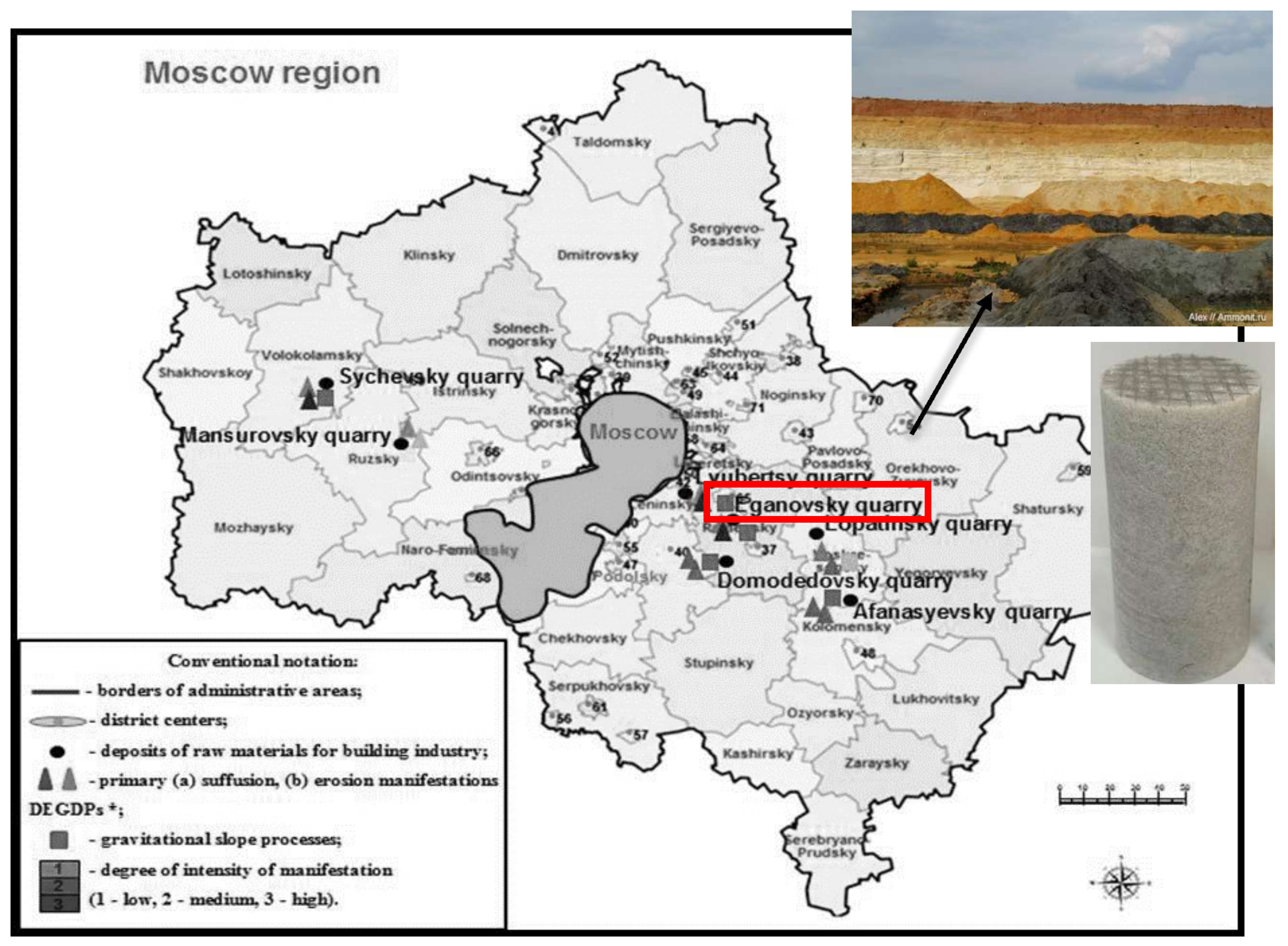
Light-gray homogeneous sandstone of the Eganovsky quarry, Moscow region (Figure 2), was selected, with a porosity of 3.7% and a permeability of 1.59 mD (Table 1). The structure of the material is fine-grained with no significant inclusions. The pores are small (0.02–0.5 mm), and partial filling with carbonate cement is observed. The mineral composition of the rock is: quartz—62%, feldspar—28%, clay substances—6%, hematite—1%, and other minerals—3%.
Specimen preparation started with drilling of a cylindrical specimen from a rock block. Then, the end surfaces of the specimen were ground using a diamond grinding disc to a maximum flatness deviation of no more than 0.03 mm. To simulate a horizontal wellbore (cased well and open-hole sections), a side hole with a diameter of 5 mm was drilled in the specimen. A metal tube of 3.2 mm diameter was glued into this hole (cased well section), with a section of 10 mm long in the central part of the cylinder left open (open-hole section).
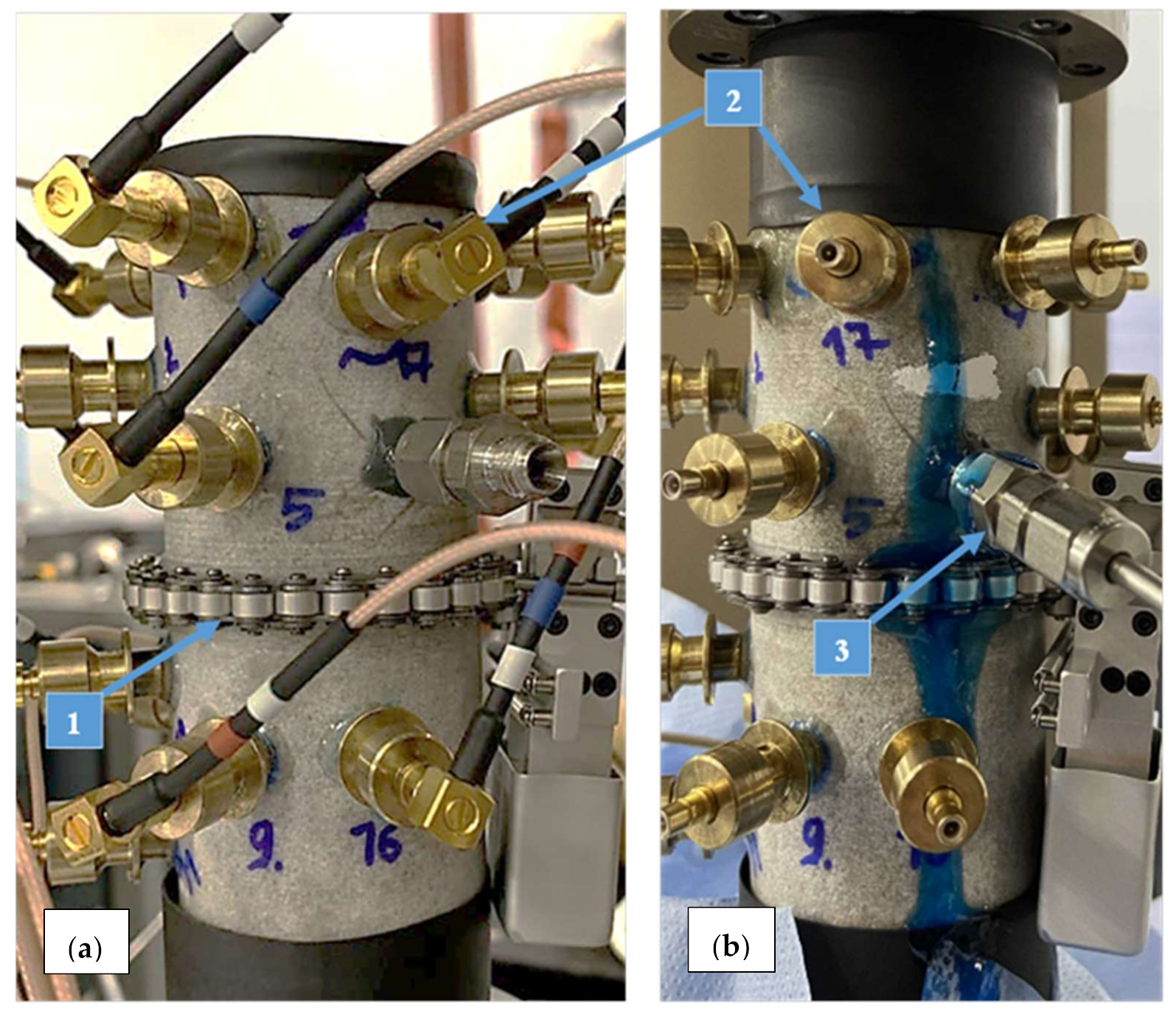
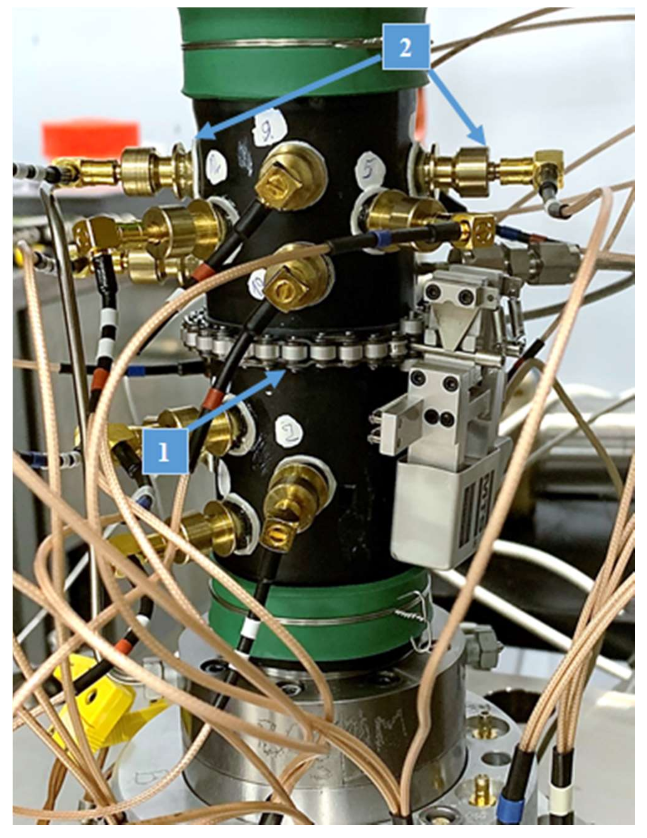
The next step was to install piezoelectric sensors onto the cylindrical surface of the specimen. Acoustic emission (AE) sensors were glued directly onto the sandstone specimen using epoxy resin (Figure 3 (2)), allowing to monitor the dynamics of hydraulic fracturing. The sensors recorded elastic waves emitted by the cracks created during the experiments. AE sensors can register elastic waves at pressures up to 140 MPa and temperatures up to 180 °C. Next, a circumferential extensometer was installed on the specimen to measure the transverse (radial) deformation in the middle part of the specimen (Figure 3 (1)). It consists of a roller chain that surrounds the specimen and a clip gauge attached to the ends of the chain. This test system allows conducting experiments following the ISRM (International Society for Rock Mechanics and Rock Engineering) regulations, with the measurement of both the radial deformation of the specimen and the pressure applied to the specimen. After installing the extensometer and AE sensors, the specimen was placed between the upper and lower plungers of the press for the laboratory study.
Figure 3a shows a photograph of a sandstone specimen prior to testing. The sandstone specimen was loaded in the axial direction to 16.4 MPa in a MTS-815 rock mechanics test system. Thereafter, the PMS silicone oil (polymethylsiloxane) with a viscosity of 100,000 cP was injected into the wellbore drilled into the specimen. The injection was carried out at a constant rate of 0.5 mL/min.
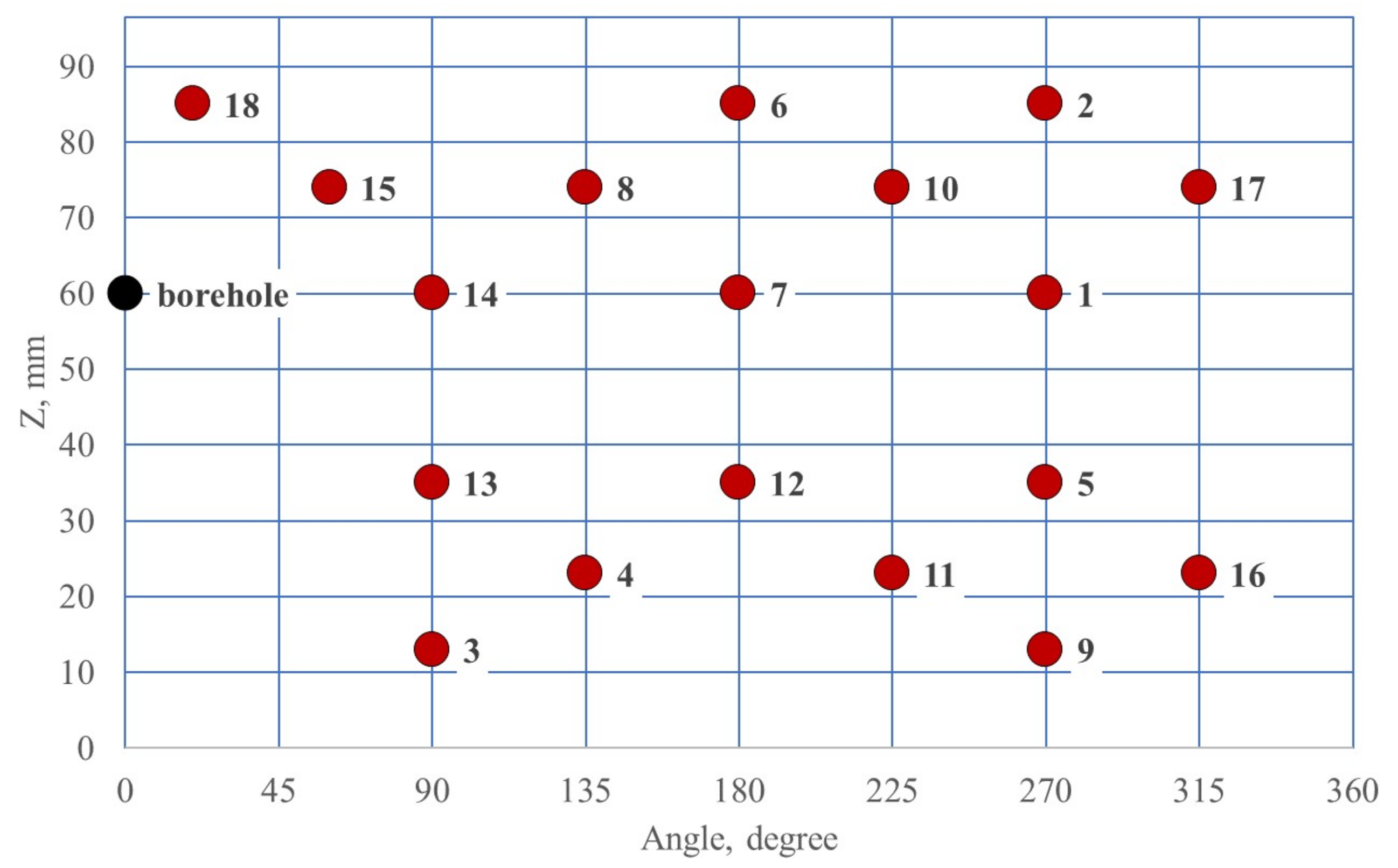
Acoustic emission was monitored using 18 single-component piezoelectric sensors attached directly to the cylindrical surface of the specimen. Locations of wellbore (black circles) and AE sensors (red circles) for sandstone and shale-like samples are shown in Figure 4 and Figure 5, correspondingly. The waveforms were continuously recorded with a sampling frequency of 10 MHz and a resolution of 16 bits using a Richter system manufactured by Itasca Consulting Group, Inc. (Minneapolis, MN, USA). A bandpass filter with a cutoff frequency of 50 kHz low and 750 kHz high was applied to the data to remove noise before further processing. The resonant frequency of the transducers is about 1 MHz. Once the triggering condition was reached, the AE waveforms were extracted from the continuous recording, and a 2048-point time series was saved for further waveform analysis for each acquisition channel. The use of 18 sensors provided sufficient coverage of the specimen for both localization of the radiation sources and inverting the moment tensor. The ultrasonic transmission of longitudinal (P) waves was performed in different directions with the same piezoelectric transducers as for the AE recording, but by applying an electric pulse with an amplitude of 450 V to each of the installed transducers in turn. During ultrasonic transmission, the remaining 17 transducers acted as receivers of elastic waves, which allowed measuring P-wave velocities in different directions. To characterize anisotropic velocities in tested samples, we applied the vertical transverse isotropy (VTI) model of P-wave velocity, and searched for the vertical (PV) and the horizontal (PH) components of P-wave velocities, providing the best fit between modeled velocities and those measured along all ultrasonic transmission traces with different inclinations to the vertical axis of the sample [27]. The velocities were periodically measured during the test and then calculated anisotropic velocities were used to calculate the hypocenter coordinates of the recorded AE events.
The technique of automatic localization of AE signals for the anisotropic velocity model has been described in some detail earlier, for example, in [19,28,29]. The Akaike Information Criterion method, widely used in seismology [30], was applied to automatically determine the moments of the first arrivals of AE signals. The Simplex algorithm [31] was used to localize the AE signals. We estimate the AE location accuracy to be about 2.5 mm for the MSS-401 sandstone sample and about 5 mm for shale-like samples.

2.2.2. Characterization of Shale-Like Rock Samples and Preparation for Testing

Six samples of siliceous-bituminous-carbonate rocks were provided for research by RITEK LLC. The company operates in 10 constituent entities of the Russian Federation, specializing in producing, testing, and implementing new technologies of unconventional hydrocarbon production and enhancing oil recovery.
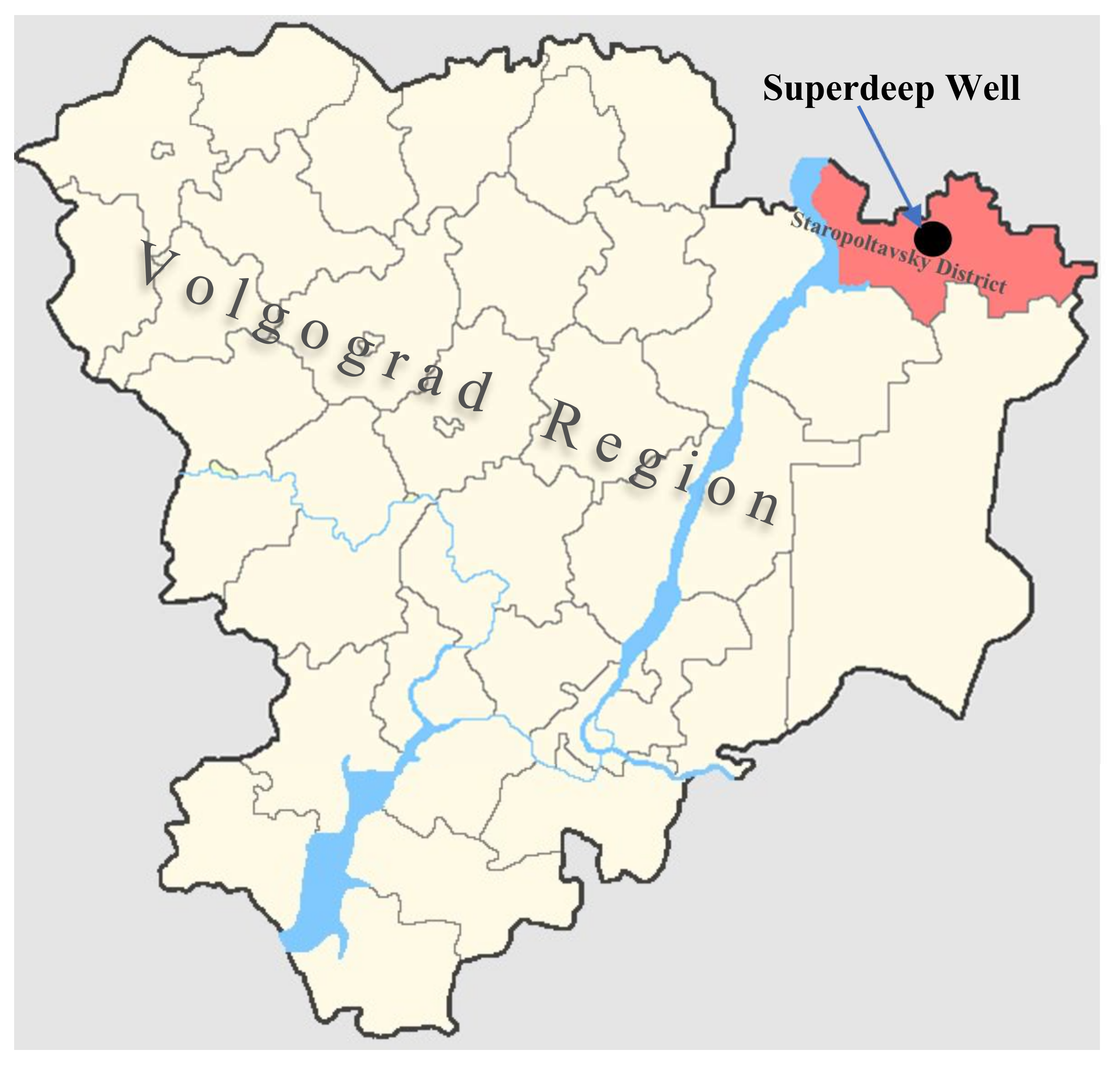
Samples were taken from a place nearby Volgograd region (Figure 6) from sediments of the Artinskian stage of the subsalt complex. The Lower Permian terrigenous-carbonate deposits were previously found to be productive in the area of the Caspian depression (gas condensate and oil fields) [32]. The well with a depth of 6300 m is located on the left bank of the Volga on the Eruslan gas-condensate structure, which corresponds to the northern part of the Akhtubinsko-Eruslan megaswell. In the study of the core of the lower Artinskian sediments of the superdeep well, direct signs of oil and gas bearing were recorded, expressed in anomalous concentrations of free hydrocarbons (HC), which are at the level of 10−1–10−2%, being an order of magnitude higher than the background (10−3) [33].
The provided samples correspond to five different members with a similar layered structure and composition. They were taken from different depths and demonstrated different strength characteristics. The rocks of the Lower Permian are represented by carbonate cyclical formations of the Asselian, Sakmarian and Artinskian, and anhydrite-dolomite Artinskian sequence [34].
The lithological description provided above is comparable to that of Domanic shale rocks with similar composition. In turn, the predominant mineral composition of the Domanic formation is close to one of the largest shale deposits in the United States, Eagle Ford [35]. Therefore, further in the text, when describing the studied samples, the term shale-like rocks will be used.
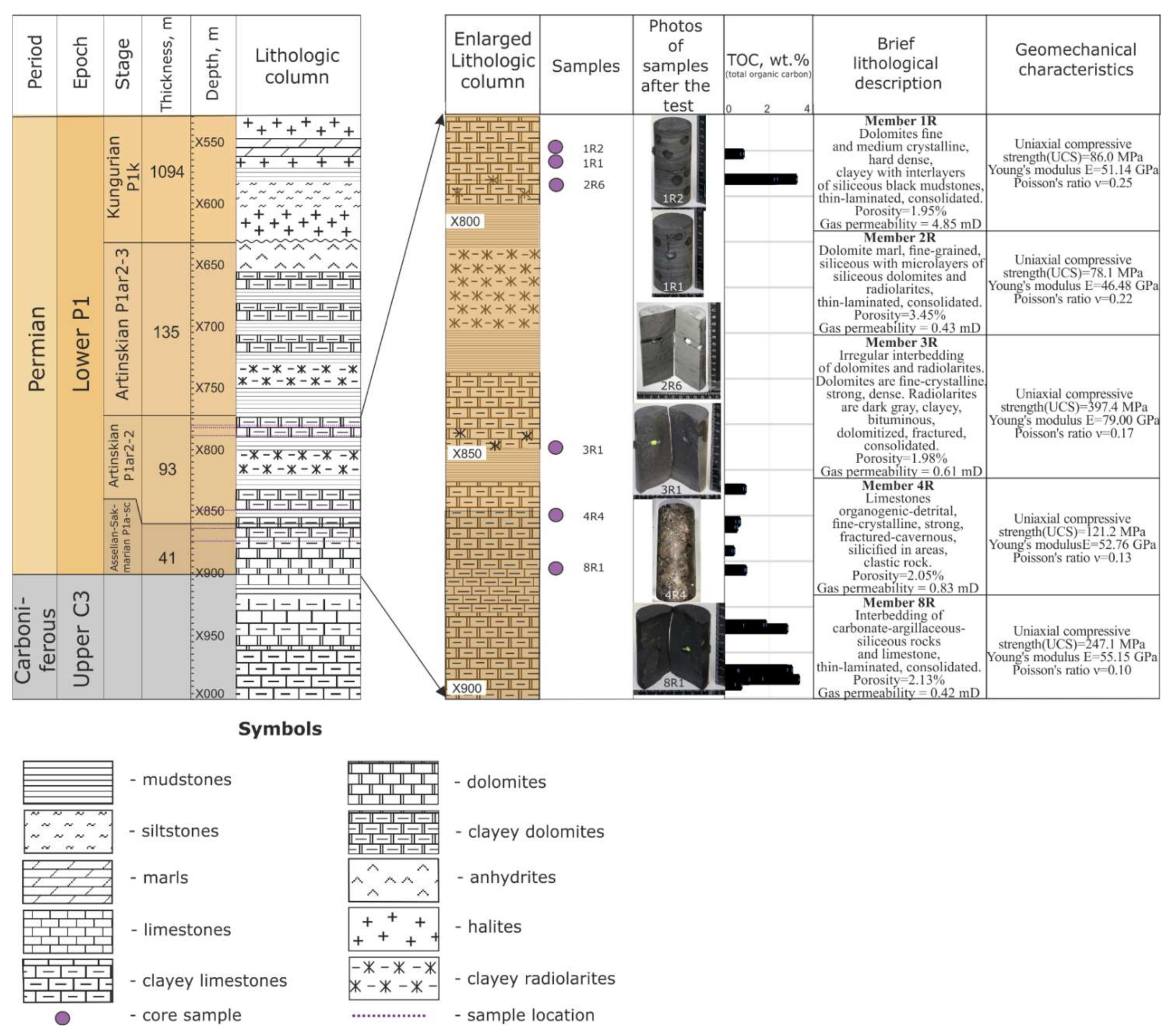
A brief lithological and stratigraphic description of rocks, total organic carbon (TOC) concentration, and geomechanical characteristics of the members from the deposits of the Artinskian stage are presented in Figure 7. Members 2, 3, 4, and 8 can be attributed to the poorly permeable reservoir class (0.42–0.83 mD). The permeability of sediments of member 1, which is 4.85 mD, is significantly higher and corresponds to the low-permeability class of reservoirs.
This deposit is predominantly composed of carbonate and clayey rocks with an admixture of siliceous radiolarians. While the carbonate component is present in all the members, the siliceous rocks are contained in members No. 2, 3, and 8. Moreover, member number 8 corresponds to a uniform interbedding of carbonate, clayey, and siliceous rocks. The TOC concentrations vary considerably up to 3 wt.% for different lithological units within a cross-section.
The samples taken from the lithotypes mentioned above were comprehensively characterized using the following geomechanical studies: Brazilian test (to determine tensile strength), uniaxial compression (to determine UCS), and multi-stage testing (to determine moduli, internal friction angle, and cohesion). The generalized results of geomechanical studies are shown in Table 2. The highest tensile and compressive strengths are observed for specimens from members 8 and 3. It should be noted that the samples from member 3 have the highest rock strength. The highest Young’s moduli was demonstrated in samples 3, 8, and 4 (UCS). Correlation of elastic-strength characteristics with the depth was not observed. Detailed mechanical and physical properties are shown in Table 2.
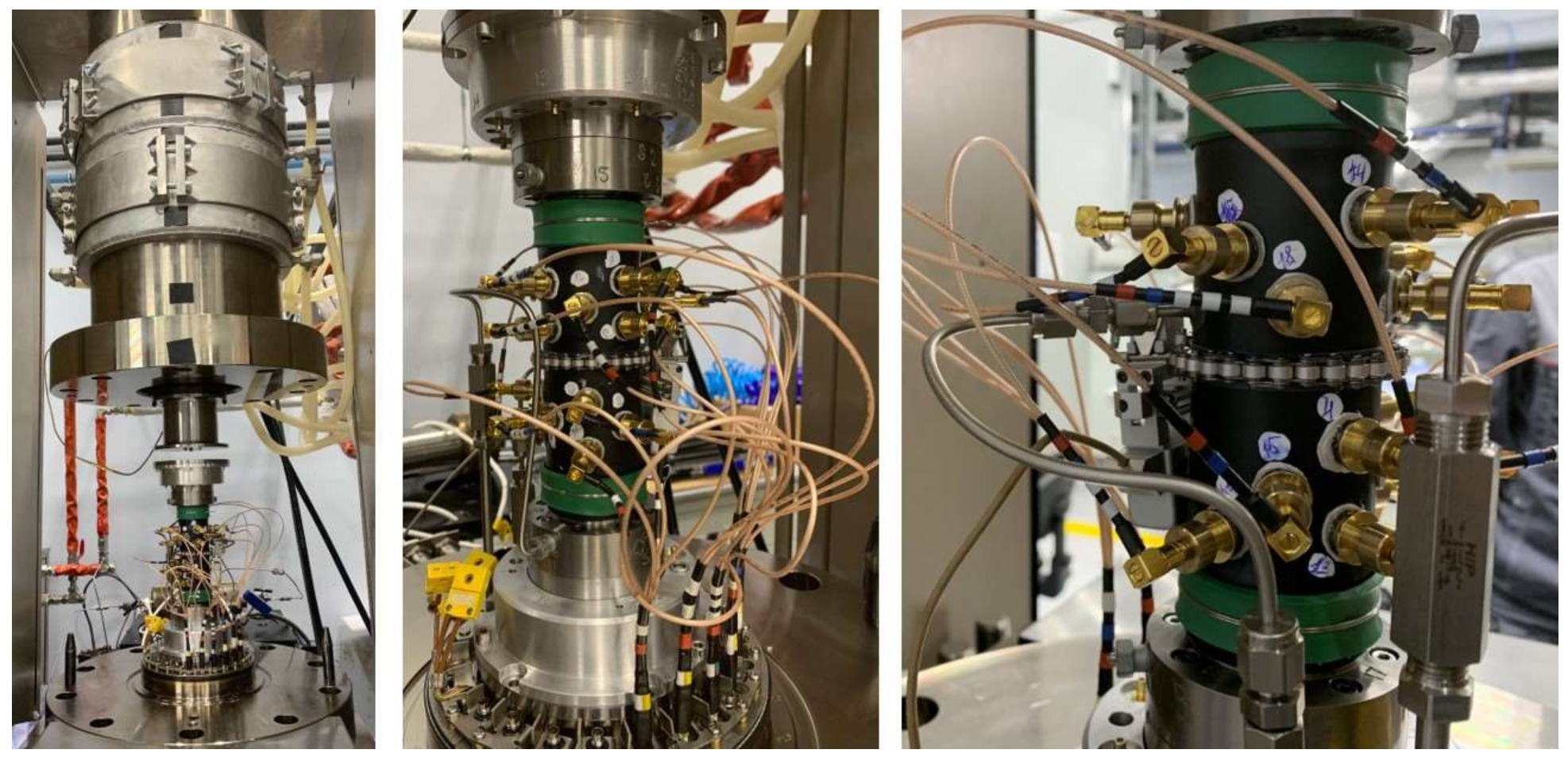
Shale-like rock samples were hydraulically fractured in a pressure chamber of an MTS press under confining pressure, representing reservoir conditions. Each sample was placed in a sealed oil-resistant jacket to isolate the rock from the silicone oil that was used to apply the confining pressure to the sample. There were 18 holes made in the jacket to install piezoelectric sensors. Sensors were glued directly to the cylindrical surface of the rock using a two-component elastic epoxy resin, which provided sealing of the jacket after the AE sensors were installed (Figure 8).
The experiments were carried out under pseudo-triaxial stress conditions using an MTS 815/S-ATM servo-hydraulic system. The fracturing of the sample installed inside the triaxial apparatus was initiated by applying an axial (vertical) load (σ1), confining (radial) stress (σ3), and injecting MultiTherm PG-1 mineral oil with a viscosity of around 46 cP into a wellbore drilled into the sample. The injection was carried out at a constant rate of 5 mL/min. All experiments were conducted under stress conditions with σ1 = 54.8 MPa and σ3 = 27.4 MPa, where σ1 was applied along the cylinder axis, and σ2 = σ3 was applied as the confining pressure (Figure 9).
Vertical (lithostatic) stress was determined by integrating density with depth using a density log curve:
σ V = 0 z ρ z g d z = ρ ¯ g z
where σ V —vertical stress, MPa; ρ—bulk density, g/cm3; g—acceleration of gravity, m/s2; z—depth at absolute elevation, m; ρ ¯ —mean bulk density for the depth z, g/cm3.
Confining pressure was calculated using the hydrostatic pressure formula with further calibration for calculations based on actual formation pressure measurements.
Fracture propagation was monitored using acoustic emission (AE), ultrasonic transmission (UT), and volumetric deformation methods. A photograph of a pseudo-triaxial stress cell with integrated acoustic sensors is shown in Figure 9.
The transducers are sensitive to the particle motion normal to the sample surface, allowing detection of normal incident compression P-waves. For the correct calculation of the moment tensors of the AE signals, the polarity of the recorded electrical signal should be known when a compression wave approaches the AE sensor. Therefore, before the experiments, a preliminary calibration of the transducers was carried out using a free fall of a steel ball with a diameter of 1 mm, which showed the recording of the positive polarity of the first motion of a longitudinal wave when a compression wave arrived at the transducer.
X-ray computer tomographic (CT) images of the specimens were taken before and after hydraulic fracturing. Post-test images allow obtaining more detailed information about the geometry and shape of the created hydraulic fracture.

3. Results

3.1. Propagation of Hydraulic Fracture in Sandstone

At the initial stage of injection, pressure in the wellbore was increasing linearly, but starting from a particular moment, the rate of pressure rise decreased, then the pressure reached its maximum value, and soon, there was a sharp pressure drop, indicating hydraulic fracturing of the specimen. Video filming of the sandstone specimen confirmed that the moment of a sharp drop in the wellbore pressure corresponded to the appearance of the liquid on the specimen surface, then the injection was stopped, and the specimen was unloaded. A post-test photo of the specimen is shown in Figure 3b. A blue dye was added to the silicone oil, and the blue fluid in Figure 3b confirms oil leakage through the hydraulic fracture. According to [14], the entire volume of fluid injected into the specimen can be divided into two components: (1) the volume of fluid linearly increasing with pressure, associated with the elastic expansion of the elements of the hydraulic system, the compressibility of the fluid, and of the rock, and (2) a part of the fluid volume that nonlinearly increases with pressure, associated with other processes, including the filling of cracks and pores during the propagation of a hydraulic fracture.
Analysis of the linearly increasing part of the relationship of fluid pressure versus injected volume showed that the slope was equal to 4.14 MPa/mL. This value was used to calculate the volume of fluid injected into the fracture. According to [14], the beginning of an increase in this volume of fluid can indicate the start of fluid penetration into the opened hydraulic fracture. If we know the dimensions of hydraulic fracture, and if we can neglect the fluid leak-off into the matrix, then the value of this volume allows us to estimate the aperture of the hydraulic fracture. Other additional criteria for the initiation of hydraulic fracture opening were the beginning of an increase in the sample diameter, recorded by the radial extensometer shown in Figure 3 (1), and an increase in the number of AE signals recorded by sensors shown in Figure 3 (2).
For the sandstone specimen, the vertical component of P-wave velocity (PV) was determined to be 5241 m/s, and the horizontal component PH = 4567 m/s. These values were used in an anisotropic velocity model to localize the coordinates of AE sources. We define P-wave anisotropy as A p = P V P H P V [28], and for the sandstone sample, the anisotropy is AP = 12.9%. Note that for sandstone, the P-wave velocity in the vertical direction was found to be higher than in the horizontal direction, which we explain by the appearance of stress-induced anisotropy of the sandstone sample caused by the closure of horizontally oriented pre-existing cracks during the uniaxial loading of the sample, in good agreement with [28].
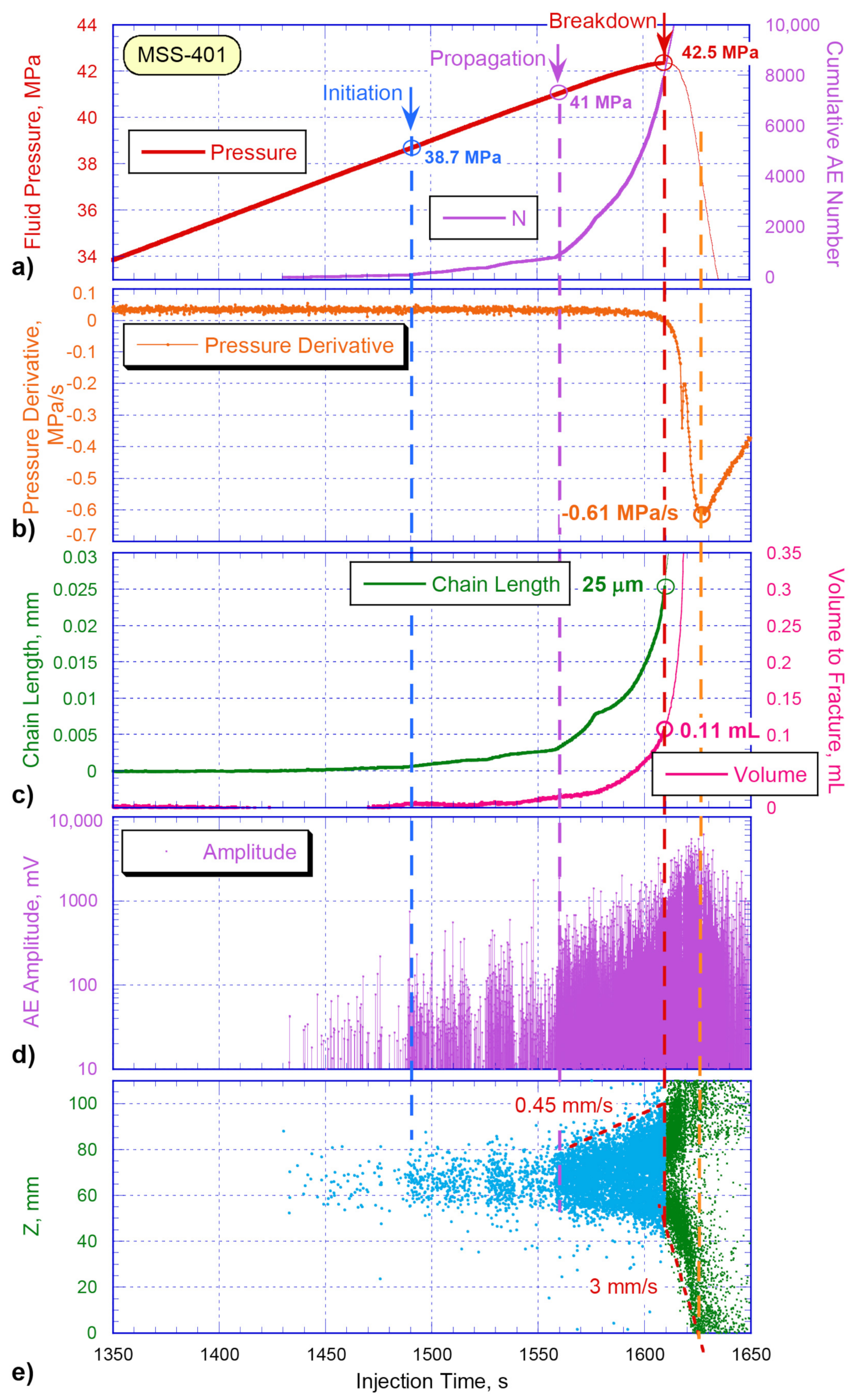
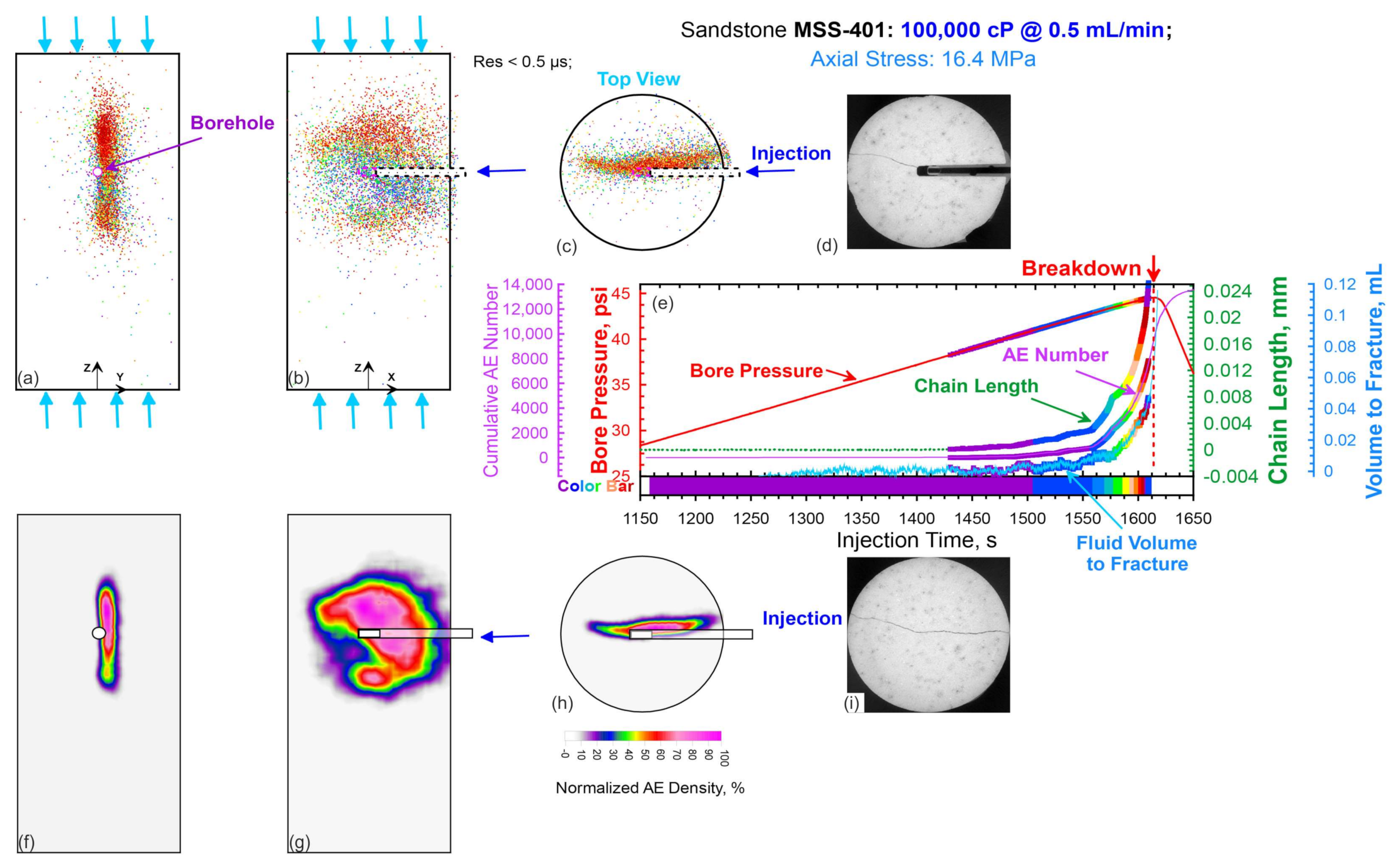
Figure 10 shows the history of changes in hydraulic, mechanical, and acoustic parameters recorded during the injection of silicone oil with a viscosity of 100,000 cP at a rate of 0.5 mL/min into a wellbore drilled perpendicularly to the maximum principal stress direction at the height of 70 mm from the base of the sample, which was taken as the origin of the Z coordinate. It can be observed that during the initial stage of fluid injection, until approximately 1490 s (Figure 10, light blue vertical dashed line), the wellbore pressure increases linearly (Figure 10a, red curve). After reaching a pressure of approximately 38.5 MPa, increased activity of acoustic emission signals is observed (Figure 10a, purple curve). This moment coincides with the beginning of recording of the increase in the sample diameter, independently measured by the sensor of the radial deformation of the sample (Figure 10c, green curve). The amplitude of the AE signals was calculated, taking into account the geometric factor of elastic waves’ propagation, taking into account the amplitudes of all channels used to localize the source [28,36], which allows us to consider the amplitude as a characteristic of the radiation source. Figure 10d shows that after the initiation of a hydraulic fracture, the amplitudes of most AE signals exceed 100 mV, while the vertical Z coordinate of these signals is in the range of 60–80 mm (Figure 10e). Coordinates of these events are at a distance of several millimeters from the wellbore (Z = 70 mm). At the same time, the volume of fluid injected into the hydraulic fracture remains close to zero for about 50 s after the initiation of hydraulic fracturing (Figure 10c, magenta curve). We think it occurred due to the unfeasibility of a viscous fluid to penetrate microcracks with a small opening. However, after 1540 s, this independently recorded parameter also shows an increase (Figure 10c).
At approximately 1560 s, a significant increase in AE activity is observed (Figure 10a, purple curve), coinciding with the moment of acceleration of the increase in the sample diameter (Figure 10c, green curve), with an increase in the volume of fluid injected into the hydraulic fracture (Figure 10c, magenta curve), and with a significant increase in the amplitude of the AE signals (Figure 10d). This point in time is marked in Figure 10 with a vertical purple dashed line. Spatial analysis of the Z coordinate shows the propagation of AE signals at a speed of approximately 0.45 mm/s (Figure 10e). At the moment of 1610 s, the wellbore pressure reached a maximum value of 42.5 MPa. This moment is called breakdown and is marked with a red dashed line in Figure 10. Thereafter, a rather rapid pressure drop was observed (Figure 10a, red curve). Analysis of the spatial distribution of the AE signals shows that at the moment of breakdown, AE signals were recorded at coordinate Z ≈ 108 mm, which corresponds to the upper end of the sandstone sample (Figure 10e). Video recording of the sample testing revealed the appearance of a blue fluid on the cylindrical surface of the sample shortly after this point. These observations led to the conclusion that the fluid was leaking out of the specimen through the created hydraulic fracture, leading to a pressure drop in the wellbore. Z-coordinates of the AE signals recorded after the breakdown moment are marked by the green dots in Figure 10e. The results confirmed that after reaching the maximum pressure in the wellbore, accelerated propagation of the hydraulic fracture in the vertical direction continued at a speed of approximately 3 mm/s (Figure 10e). During this interval, the amplitudes of the AE signals proceeded to increase (Figure 10d), approximately until the moment when the hydraulic fracture reached the lower edge of the sample. Figure 10b shows the derivative of the fluid pressure in the wellbore (Figure 10a, red curve). The moment when the rate of pressure drop in the wellbore reached the minimum negative value is marked with an orange vertical dashed line in Figure 10. This moment turned out to be very close to the moments when the maximum amplitudes of the AE signals were observed (Figure 10d), as well as when the hydraulic fracture reached the lower edge of the sample (Figure 10e). This correspondence is explained by the assumption that after the fracture reaches the bottom edge, the sample gets split into two parts by the hydraulic fracture, and the viscous fluid flows out of the fracture, demonstrating the highest rate of pressure drop in the wellbore.
Thus, the analysis of the dynamics of changes of several independently recorded parameters leads to a conclusion that when injecting a fluid with a viscosity of 100,000 cP into the sandstone specimen at a rate of 0.5 mL/min, the initiation of a hydraulic fracture is observed approximately 2 min before the maximum pressure in the wellbore is reached (Figure 10). After the initiation of hydraulic fracturing for about 70 s, the fracture process remained concentrated within several millimeters around the wellbore. About 50 s before the maximum pressure is reached, the hydraulic fracture began to propagate at an approximate rate of 0.45 mm/s until it reached the top edge of the sample. After that, there was a wellbore pressure drop associated with the fluid leak out of the specimen through the formed hydraulic fracture.
The analysis of the three-dimensional spatial distribution of the AE signals shown in Figure 11 is of particular interest. The upper part of Figure 11a–c demonstrates three orthogonal projections of the AE signals, which were recorded before detecting the maximum pressure in the wellbore. The color of the dots corresponds to the recording time of AE signals, according to the rainbow color scale: violet color indicates the earliest recorded signals, then blue, green, etc., and the red colored dots display the last recorded signals. The lower part of Figure 11f–h shows three orthogonal projections of the spatial densities of the AE signals, built on the basis of the calculation of the AE signal densities inside a cube with a size of 0.5 × 0.5 × 0.5 cm sliding over the entire volume of the sample and normalized to the maximum value of the density of AE signals recorded in each projection. Figure 11e displays the parameters shown above in Figure 10, where the color of the dots correspond to the same color range as in Figure 11a–c. The X-ray scan shown in Figure 11d was taken in the center of the borehole and shows a hydraulic fracture passing through the sample from the boundary of the wellbore section, left open in the center of the sample. The X-ray image, shown in Figure 11i, was taken 5 mm below the center of the wellbore. It demonstrates the fracture extending across the entire cross-section of the sample.
The projections demonstrated in Figure 11a,f confirm that the hydraulic fracture propagated in the vertical direction. The top view projections, shown in Figure 10h and Figure 11c, confirm that the hydraulic fracture was aligned with the wellbore, and their comparison with X-ray images confirms that the AE signals reflect the spatial position of the hydraulic fracture reasonably well. The projections presented in Figure 11b,g show that the shape of the hydraulic fracture is approximately pancake-like. At the moment of recording the maximum pressure in the well, the radius of this disk was close to the radius of the sample. Thus, we can conclude that the maximum pressure in the wellbore corresponds to the moment when the tip of the hydraulic fracture approaches the lateral cylindrical surface of the sample. It means that the radius of the hydraulic fracture at this moment is equal to the radius of the sample. Sandstone testing led us to the conclusion that a combination of three independently measured parameters (AE, measurements of the lateral deformation of the sample, and the volume of fluid injected into the hydraulic fracture) allows us to determine (a) the pressure at which the hydraulic fracture initiated in the vicinity of the wellbore uncased (open hole) section, (b) the pressure at which the hydraulic fracture began to propagate, and (c) the velocity of hydraulic fracture propagation. It can be assumed that the structure of the material, the presence of natural cracks, and boundaries of heterogeneity can significantly affect the dynamics of the development of a hydraulic fracture. The results of the study of this influence by means of the example of shale-like rock samples are presented below.

3.2. Comparison of Geomechanical and Acoustic Parameters of Testing Samples of Shale-Like Rocks

Before the fluid injection, ultrasonic transmissions of elastic waves through each sample were carried out in different directions. The anisotropic values of the P-wave velocities are provided in Table 3; and these values were used to localize the sources of the AE signals. Note that samples ARE-1R1 and ARE-2R6 have the highest values of absolute anisotropy (−9.5% and −12.5%, correspondingly) among all shale-like samples. The values of P-wave velocity in the vertical direction for these samples are lower than in the horizontal direction, and we explain this by the presence of bedding planes in the shale-like samples oriented orthogonally to the vertical axis.
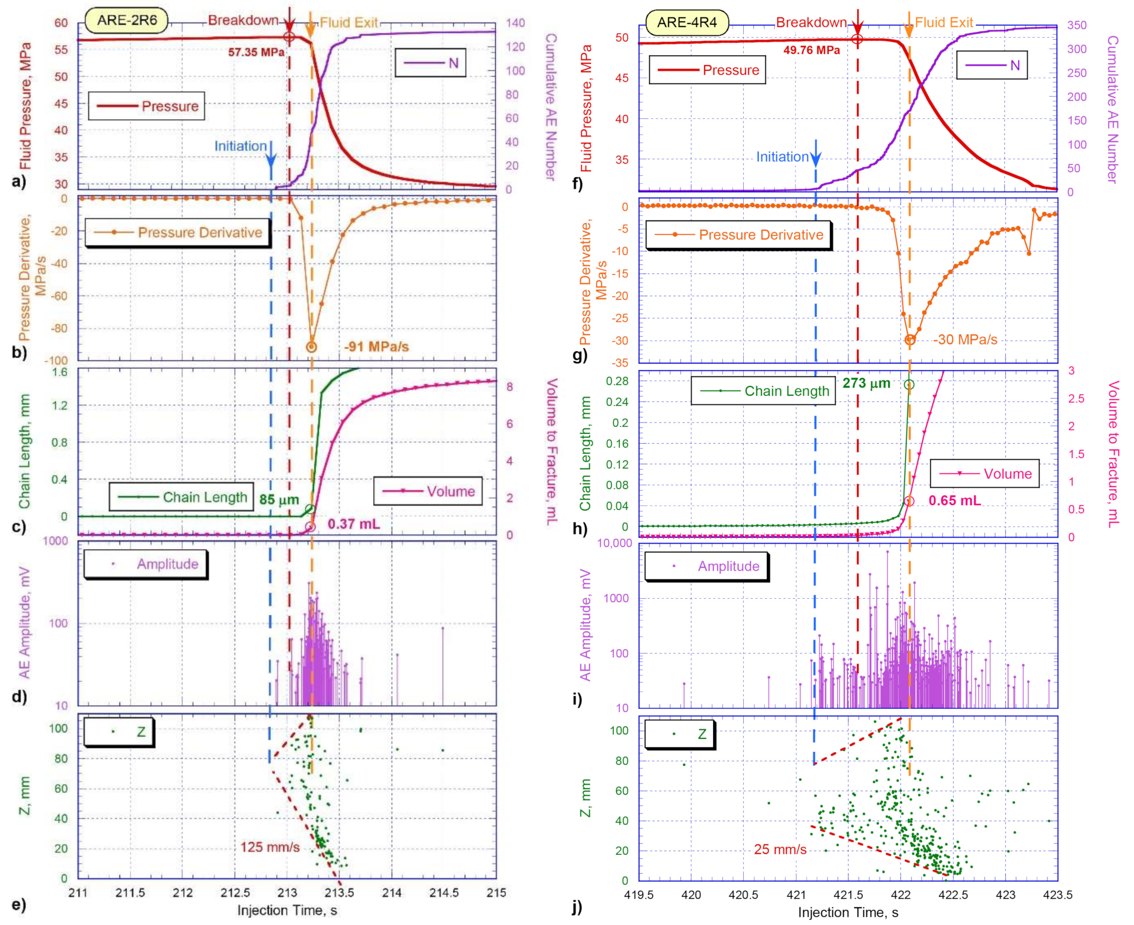
Figure 12 shows curves of the wellbore pressure, total number of AE events, derivative of the pressure, changes in the chain length and volume of fluid injected into the hydraulic fracture, amplitude of the AE signals, and vertical coordinates of localized signals versus the injection time for shale-like rock samples ARE-2R6 (left column of figures) and ARE-4R4 (right column of figures). For the convenience of the graphs’ comparison, the analysis interval for shale-like samples was chosen to be the same, equal to 4 s. Figure 12 shows that, like in the case of hydraulic fracturing of the sandstone sample, acoustic emission activities in the samples ARE-2R6 and ARE-4R4 begin before the maximum pressure in the well is recorded. Similar to sandstone testing, the moment of an increase in AE activity can be considered as the moment of initiation of a hydraulic fracture. However, the time interval between the initiation of a hydraulic fracture and the moment of maximum wellbore pressure in the shale-like rocks is much shorter than was recorded in sandstone (Figure 8): in shale-like rock samples, it is only a fraction of a second (Figure 12a,e).
Analysis of the derivative of the wellbore pressure (Figure 12b,g) shows that at the moment, marked with a vertical orange dashed line in Figure 12, the rate of the wellbore pressure change reaches a minimum negative value. This moment turned out to be very close to the moment of recording the maximum AE amplitude (Figure 12d,i) and the moment when the crack reaches the upper edge of the specimen (Figure 12e,j). The correspondence of these three independently recorded parameters suggests that the moment when the derivative of the pressure reaches its minimum value corresponds to the moment when the fracture approaches the cylindrical surface of the sample, causing the highest rate of pressure drop in the wellbore and leading to fluid leakage out of the sample.
It should be noted that the main difference in the dynamics of the parameters of the two samples presented is the significantly faster process of cracking in the ARE-2R6 sample (Figure 12, left column) compared to the ARE-4R4 sample (Figure 12, right column). It resulted in a significantly higher rate of hydraulic fracture propagation in sample ARE-2R6 (125 mm/s, Figure 12e) than in sample ARE-4R4 (25 mm/s, Figure 12j). It is also important to mention that the applied stresses, fluid viscosity, and injection rate were the same in these experiments. We suggest that the difference in the composition and structure of two samples taken from different depths was one of the main reasons for the difference in the dynamics of hydraulic fracturing development in these samples.
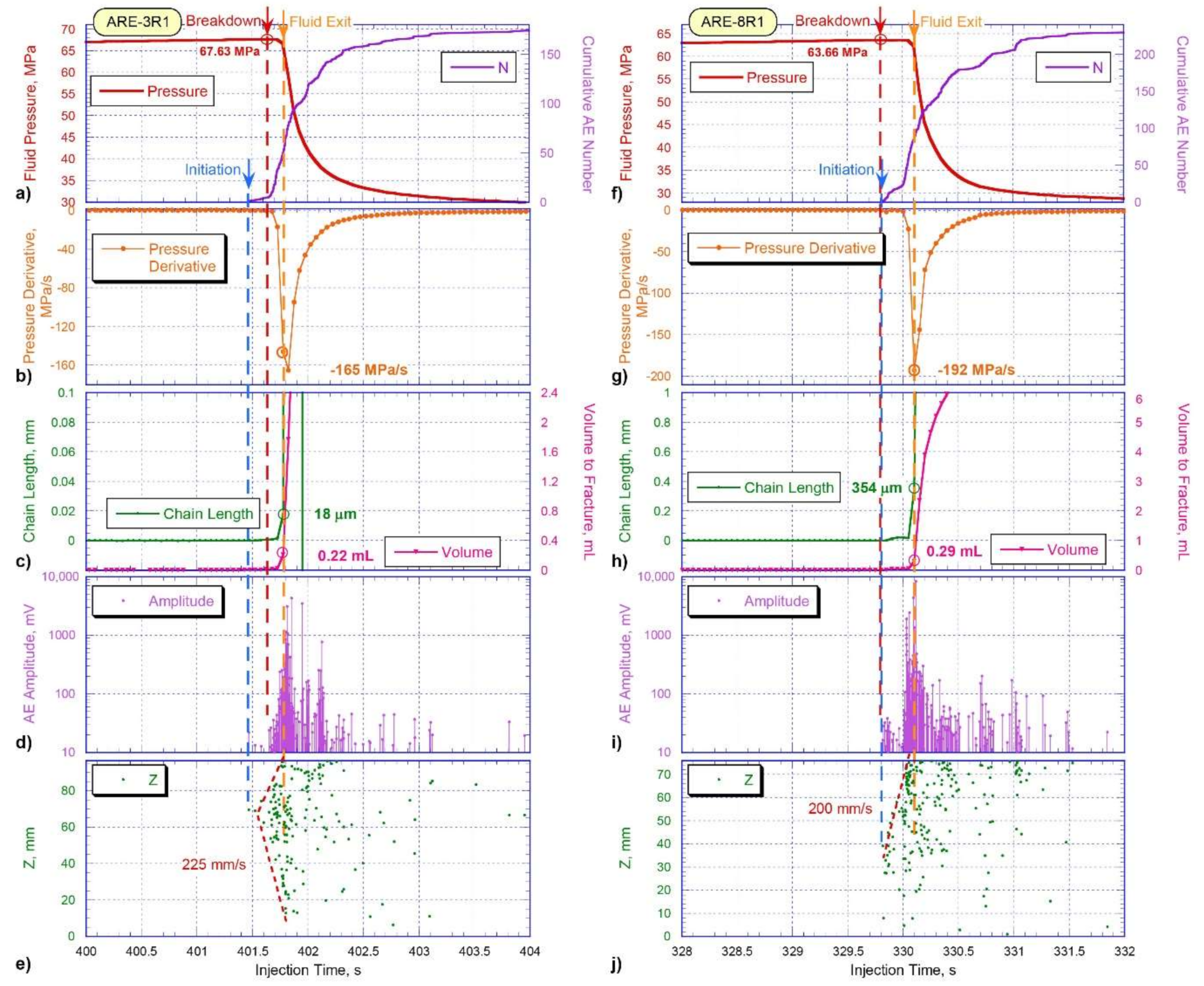
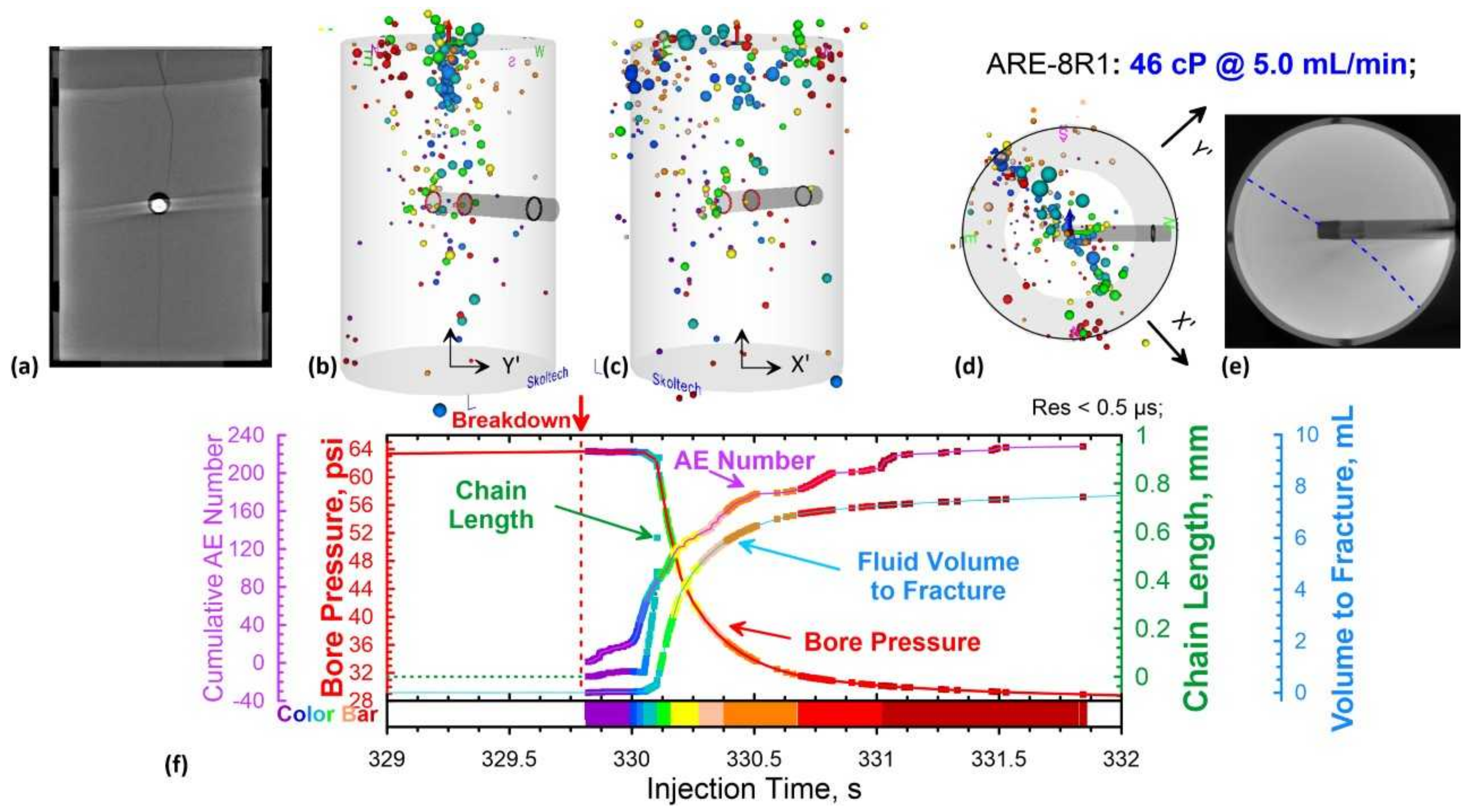
Figure 13 shows the variation of parameters using the same template as the previous Figure 12, but for a different pair of shale-like samples: ARE-3R1 (left column of figures) and ARE-8R1 (right column of figures). For sample ARE-3R1, the initiation of a hydraulic fracture (blue dashed line in the left column of graphs) was observed in fractions of a second before the maximum wellbore pressure was recorded (red dashed line in the left column). In the case of sample ARE-8R1, both moments occurred practically simultaneously (right column of graphs). The moment at which hydraulic fracture approached the upper edge of the sample (Figure 13e,j) is marked with the orange dashed line.
It should be noted that, as for the previous pair of shale-like samples, this moment: (1) corresponds to the beginning of an exponential pressure drop in the wellbore (Figure 13a,e), (2) corresponds to the recording of the maximum amplitude of the AE signals (Figure 13d,i), and (3) turned out to be very close to the moment of recording the minimum value of the pressure rate change in the wellbore (Figure 13b,g). In the case of sample ARE-3R1, the growth of the hydraulic fracture was observed symmetrically in two directions (Figure 13e). In contrast, in sample ARE-8R1, the growth of the hydraulic fracture was observed mainly from the wellbore to the upper boundary of the sample (Figure 13j). It is also important to take into account that the length of the sample ARE-8R1 was 75.76 mm, and the hole was drilled at the height of 38.50 mm, that is, approximately in the middle of the height of the sample.
Figure 14 shows the change in parameters similar to the two previous Figure 12 and Figure 13, but for the third pair of shale-like samples: ARE-1R1 (left column of figures) and ARE-1R2 (right column of figures). In the sample ARE-1R1, the moment of initiation of a hydraulic fracture, determined by an increase in the activity of AE events (blue dashed line), occurred almost simultaneously with the recording of the maximum wellbore pressure (blue dashed line), similarly to sample ARE-8R1. In the same way, the growth of a hydraulic fracture in samples ARE-1R1 and ARE-8R1 proceeded from the wellbore in only one direction—to the upper edge of the sample. In contrast, in sample ARE-1R2 (right column of graphs in Figure 14), the growth of a hydraulic fracture proceeded symmetrically in two directions, similar to the other three tested shale-like rock samples. We assume that such a difference in the hydraulic fracture behavior is also related to the difference in the composition and structure of the studied samples. Similar to all tested samples, the moments when hydraulic fracture approached the upper boundaries of samples ARE-1R1 and ARE-1R2 also corresponded to the moment of the highest amplitudes of the AE signals’ recording (Figure 12i and Figure 14d) and to the moment of the minimum negative value of wellbore pressure derivative (Figure 12g and Figure 14b). Thus, we can consider the moment marked with the orange dashed line as the moment of the beginning of fluid leaking out of the sample through the formed hydraulic fracture that has reached the sample surface.
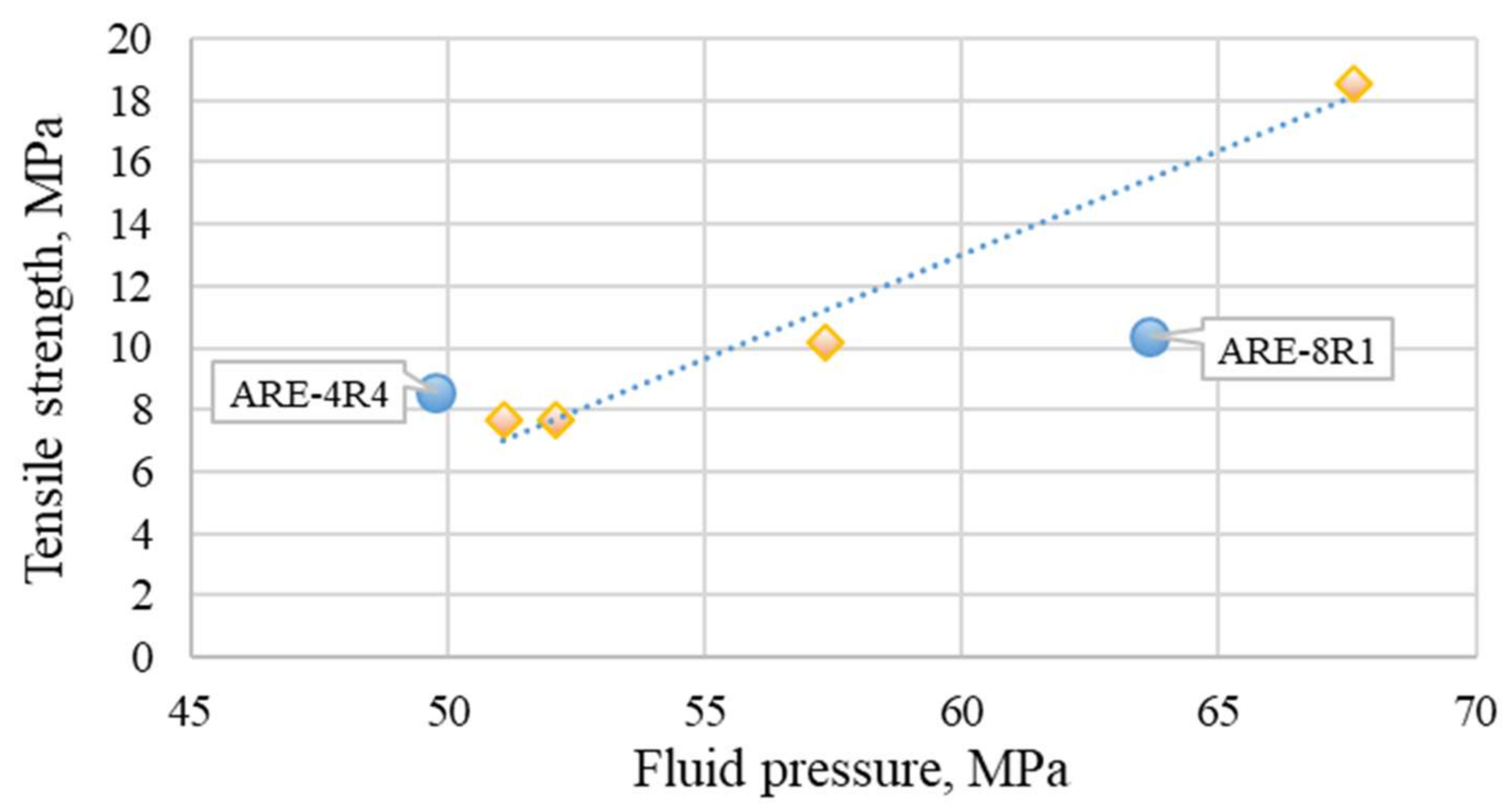
In addition, before the laboratory experiment of hydraulic fracturing, the tensile strengths for the studied materials were measured using Brazilian disk testing. One can see an almost perfect correlation of the tensile strength values with the breakdown pressure values (Table 4, Figure 15).
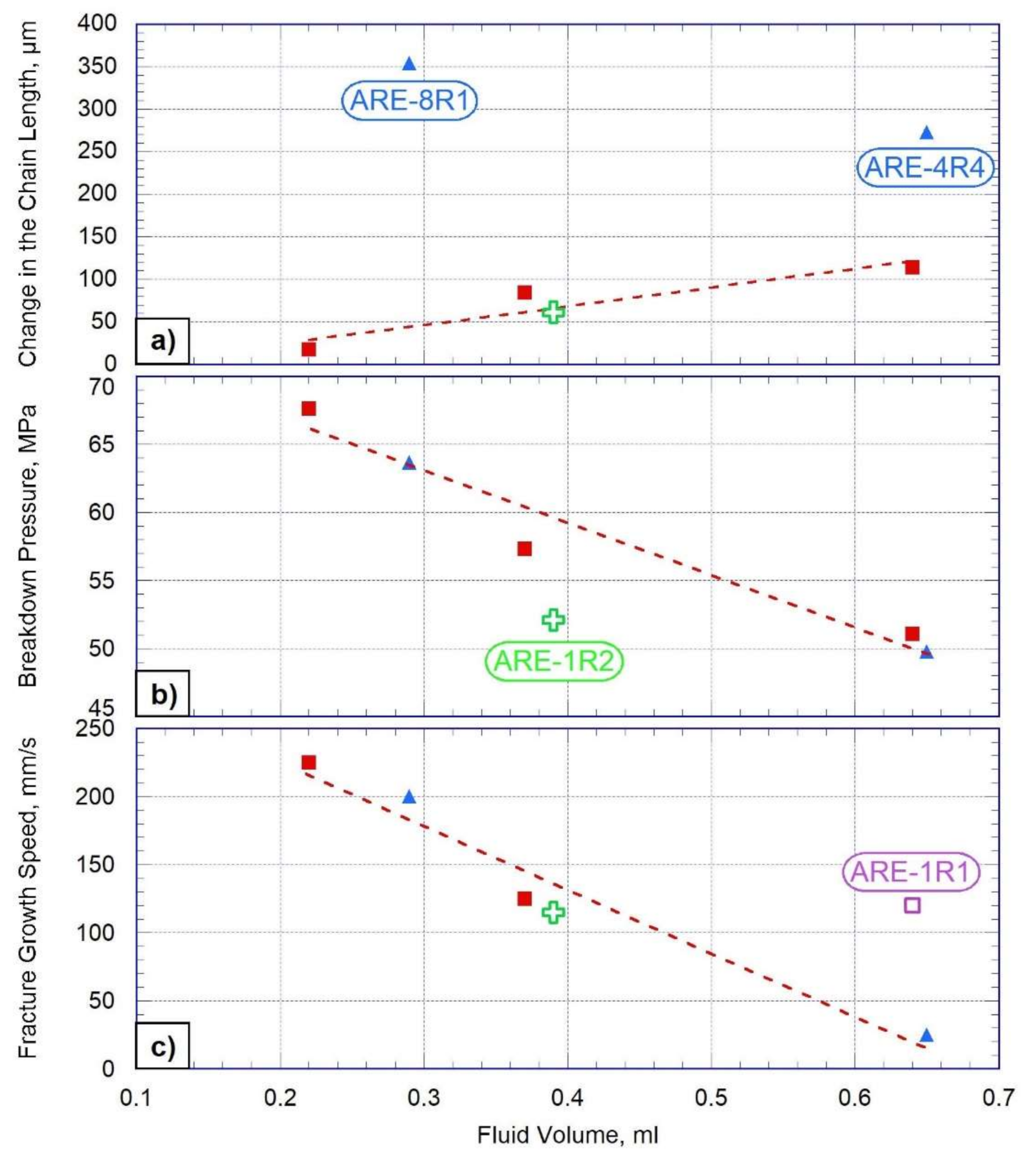
The relationship of the changes in the chain length versus fluid volumes injected into the hydraulic fracture, calculated at the moments when fluid started leaking out of the rock, is presented in Figure 16a. Experimental results show that ARE-4R4 and ARE-8R1 samples differ significantly from the remaining four samples, demonstrating considerably higher values recorded by the extensometer (Figure 16a, blue triangles). In the case of four other samples (Figure 16a, red squares, and green cross), there is an expected linear relationship, demonstrating an increase in the volume of hydraulic fracturing fluid, leading to a larger hydraulic fracture opening (Figure 16a, dashed red line).
Figure 16b shows breakdown pressure plotted versus fluid volume injected into the fracture, and one can see a linearly decreasing relationship for all tested shale-like samples. The most significant deviation from this relationship was observed for sample ARE-1R2 (Figure 16b, green cross). Fracture propagation speed plotted versus fluid volume injected into the fracture also shows a linear trend of decrease (Figure 16c, red dashed line), with the exception of one sample only, ARE-1R1 (Figure 16c, violet square). We assume that some deviations from observed linear relationships are related to the difference in the properties of tested samples.
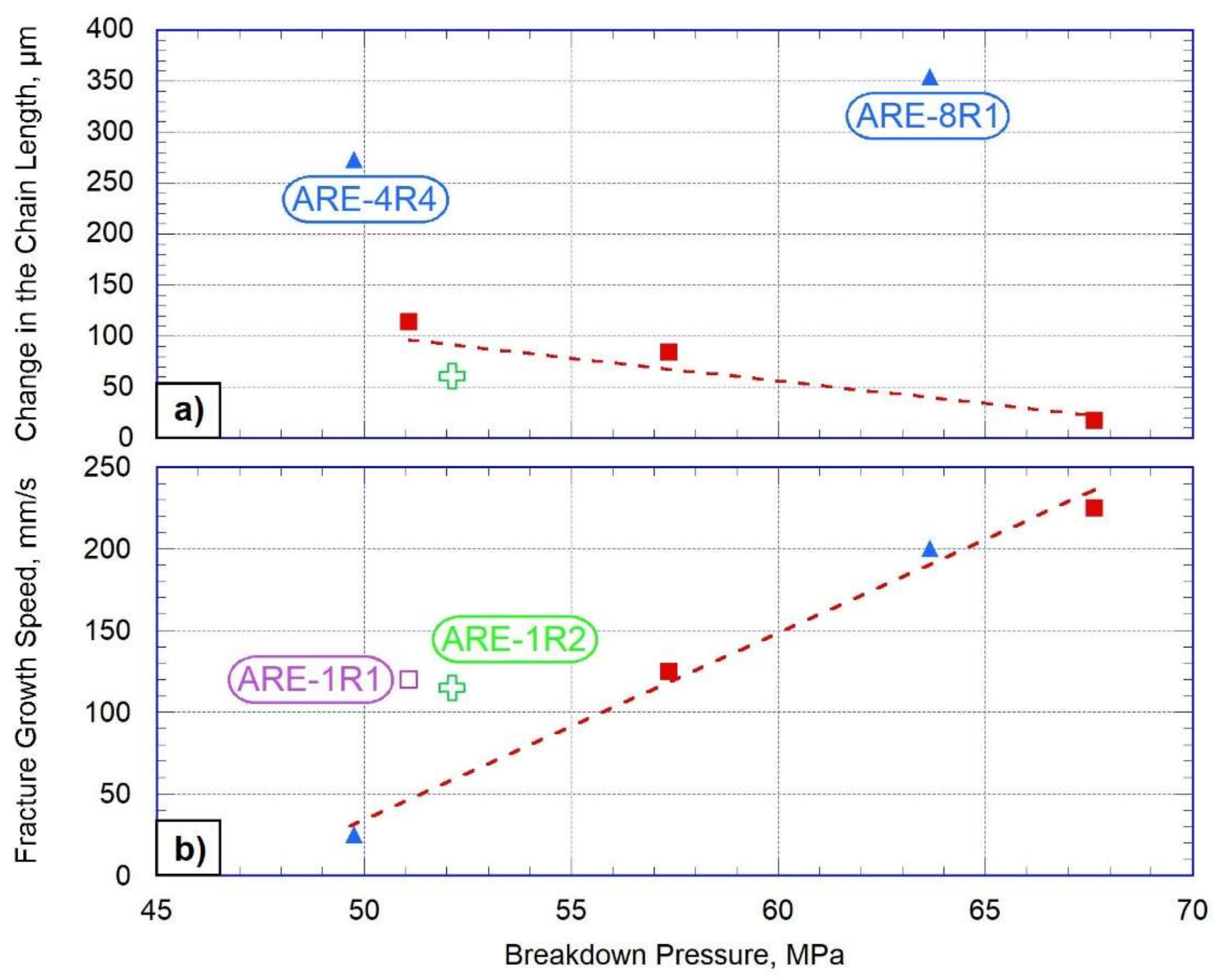
Figure 17a shows changes in the chain length versus breakdown pressure, demonstrating a general trend of decrease of the sample expansion with the increase of breakdown pressure. However, two samples, ARE-4R4 and ARE-8R1, do not obey this general trend (Figure 17a, blue triangles), which could be explained by the difference in structure and composition of these two particular samples. Figure 17b shows fracture propagation speed versus breakdown pressure, which exhibits an almost linear trend. Two samples demonstrate the most significant deviation from this linear relationship (ARE-1R1 and ARE-1R2, Figure 17b violet square and green cross, correspondingly).
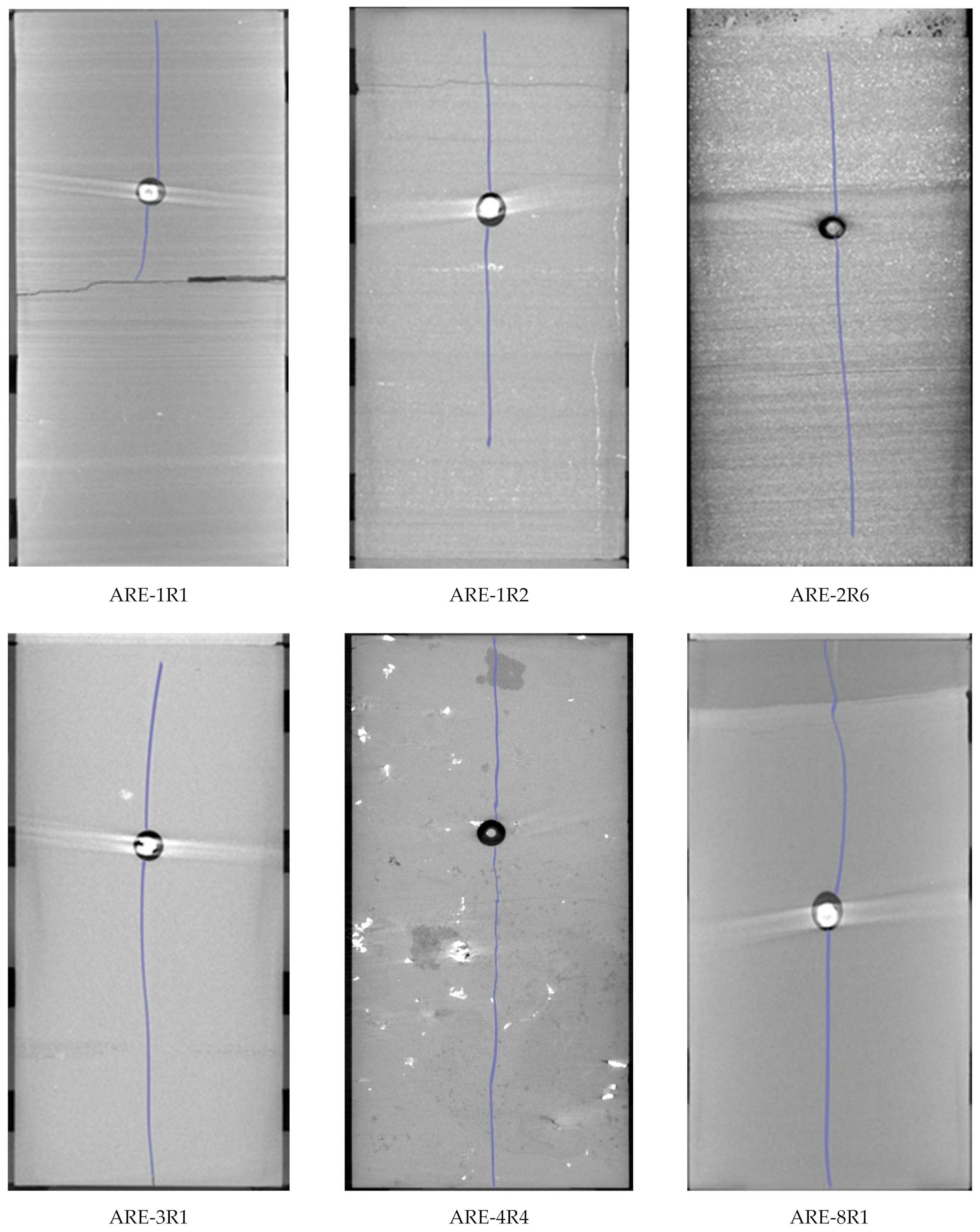
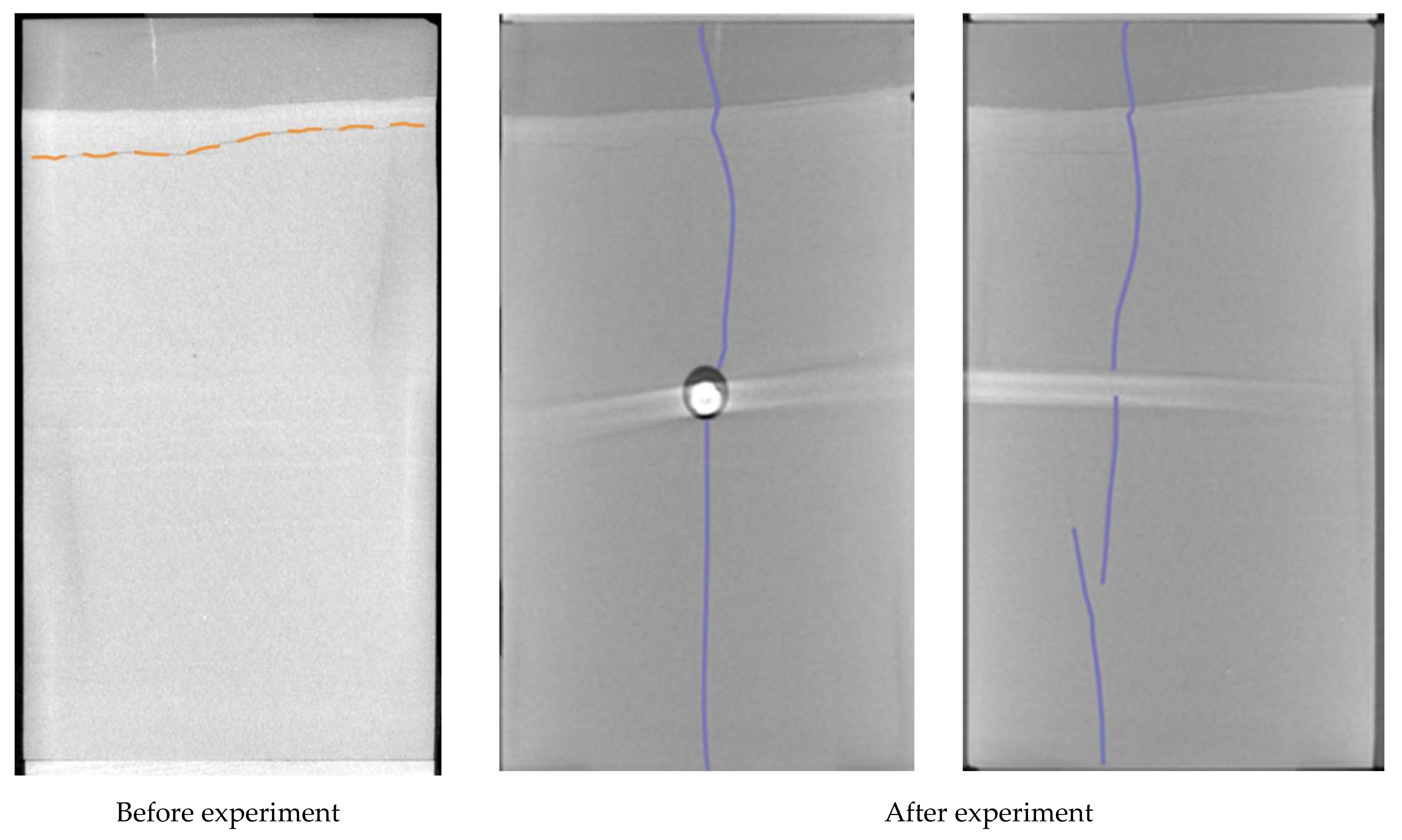
Figure 18 shows sections (vertical projection) of X-ray computed tomography scans of the tested samples after the experiments. Fractures propagated along the vertical axis of the sample, and the presence of minor deviations is associated with the presence of additional stress concentrators (initial cracks, inclusions). X-ray image of the ARE-1R1 sample clearly shows that the hydraulic fracture propagated through the upper part of the sample only and arrested in the middle of the sample at the boundary of the horizontal fracture, with a complete correspondence with the results of AE localization presented in Figure 14e.

3.3. Three-Dimensional Localization of AE Events of Shale-Like Rocks

To localize AE events, the P-wave first arrivals were analyzed automatically using the Akaike Information Criterion method [30]. The method for searching the coordinates of AE sources is based on the Simplex multiparameter search method [31] based on the isotropic velocity model.
More than 600 AE events were detected by AE transducers on the ARE-4R4 sample, 311 of which were localized with the maximum residual of 0.7 µs. The qualitative ranking of the AE data was based mainly on the signal-to-noise ratio. Generated waveforms did not always show a clear first arrival, which made the picking process quite challenging.
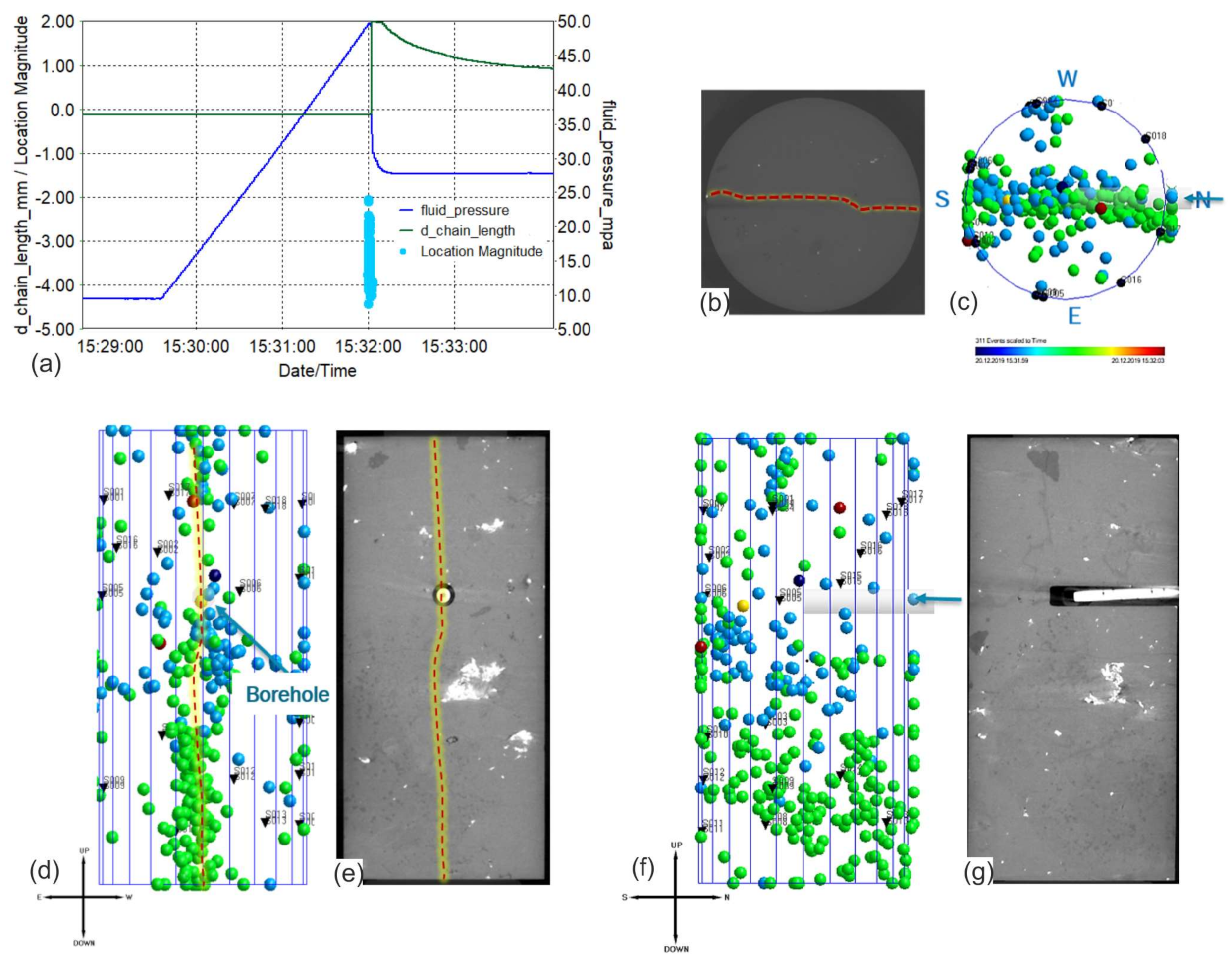
Figure 19a shows the time history of the experimental data, with blue circles demonstrating the amplitude of localized AE events. Note that all events occurred near the pressure peak within 2 min. Before the inelastic deformation stage, the sample was in a quiescent state without recording any AE events. The progress of fracturing in the sample in three orthogonal projections is shown in Figure 19c—top view, Figure 19e—EW projection, and Figure 19g—NS projection. The color of each circle corresponds to the time of AE event occurrence, according to the color timescale presented below Figure 19c. The AE cluster formed after the fracture initiation is fairly dispersed. Nevertheless, the linear components of the fracture orientation can still be traced in Figure 19c,d. For comparison purposes, near each projection of localized AE signals, corresponding X-ray CT images are presented in Figure 19b,e,g.
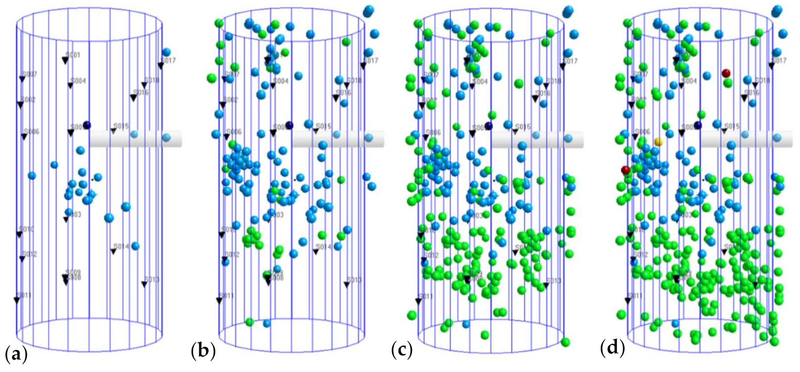
Figure 20 shows four snapshots of the 3D view of AE events’ distribution within the sample. The fracture initiation process started at the center of the sample near the wellbore, as shown in Figure 20a, and lasted a little over a minute. The AE cluster then abruptly expanded from top to bottom in approximately 60 ms, forming a plane intersecting the sample, which shows a close match with the CT results (Figure 18). After 25 ms, the main fracture reached the lower boundary, that being shown by high-amplitude AE events in the lower part of the sample (Figure 20c). During the last interval, which lasted for 40 ms, fracture opening occurred, accompanied by average-amplitude AE events (Figure 20d). Additionally, it must be pointed out that the fracture formation was also influenced by the existence of coarse grains of low density, visible in X-ray images presented earlier in Figure 18 as the dark spots. We assume that in these spots, the stress concentrations were created, causing more intensive cracking picked up by the accumulation of acoustic events (Figure 20). We assume that the presence of these coarse grains influenced the growth of the fracture since the AE sources were localized not only in the near-wellbore zone but also at the location of the grains.
Localization of the recorded AE signals for the ARE-8R1 sample in three orthogonal projections is shown in the upper part of Figure 21. The color of the circles corresponds to the time of the AE events’ occurrence, according to the color scale presented in the lower part of the graph, and the size of the circles corresponds to the amplitude of the signals. Analysis of the three-dimensional distribution of AE signals demonstrates that the circles representing the coordinates of localized AE events are unevenly distributed within the specimen. However, there is an accumulation of circles corresponding to the actual location of the fracture, which coincides with the CT image (Figure 21, top view). The circles of a larger diameter, corresponding to the higher amplitudes of AE signals, are concentrated in the upper part of the specimen, which is explained by the presence of initial fracture before the start of the test, which can be seen in the pre-test CT image. Thus, we assume that in the plane of the pre-existing fracture, there was an accumulation of the energy due to stress concentrators, which was released as the main hydraulic fracture grew and caused the appearance of high-amplitude signals.

3.4. Analysis of Moment Tensor Inversion of Shale-Like Rocks

The most common method for calculating source mechanisms is moment tensor inversion (MTI) developed by [37], which can provide the magnitude of AE events, fracture type, and fracture orientation. In contrast to sandstone, signals generated from shale-like rocks have a high noise content, so that they do not always show a clear first break. Other researchers have also encountered this problem, for instance, when performing laboratory HF on the Montney shale in [38]. Thereby, the waveforms with the optimum signal-to-noise ratios and with precisely defined polarities were selected for inversion, and the amplitudes were selected semi-automatically. At least eight channels with good-quality amplitude data are required to get inversion.
To localize AE events and determine polarities more accurately, the first arrivals of P-waves were selected manually. The grid search method was used to localize the AE hypocenters [39]. After localization of the AE events, the amplitudes of the first arrivals of the P-waves were inverted in the InSite-Lab software to obtain information about the source mechanism. Green’s functions for a point source are calculated using the isotropic velocity model with velocities measured by ultrasonic velocity surveys [39]. Knowing the mechanisms of the source of micro-seismic events, one can understand the behavior of fractures and the developing stress field within the reservoir.
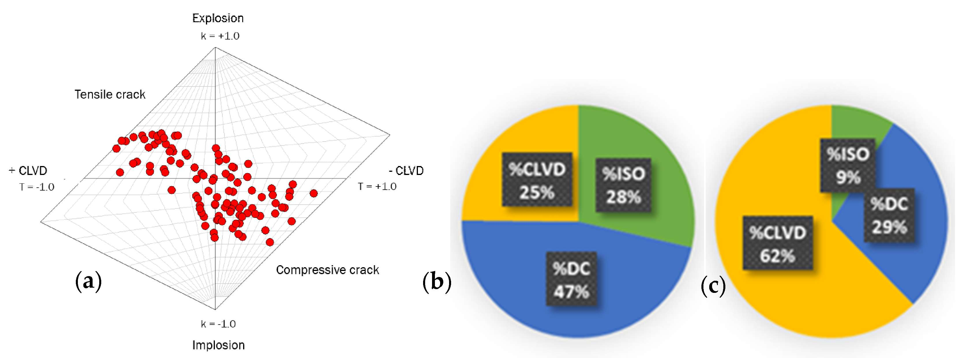
One method of representing a mechanism graphically described by a moment tensor is to use the diagram introduced by Hudson [40]. In doing so, two parameters, T and k (calculated on the basis of the eigenvalues of the moment tensor), are used to characterize the type of deviator component (constant volume component) in the source and the fraction of the volume change component respectively, with a range of values from –1 to 1 for both parameters. The Hudson diagram (Figure 22) allows representing any source mechanism depending on the double-couple ratio (DC or shear component)—in the center, compensated linear vector dipole (CLVD or component responsible for fracture opening)—values presented on the horizontal axis and isotropic energy (ISO)—values presented on the vertical axis. The smaller the T value, the closer the CLVD value is to −1, and the larger the T value, the closer to 1 CLVD. In addition, the smaller the k value, the more uniform the compression, and the larger the k value, the greater the tension.
For the ARE-4R4 sample, a total of 176 good-quality isolated events were used for the inversion. The mechanisms for the different time intervals are shown in Figure 22 in different parts of the diagram depending on the ratio of DC, CLVD, and isotropic energy.
Overall, the MTI inversion for sample ARE-4R4 showed a high isotropic component and CLVD components that are responsible for the volume change, opening, and closing of fractures under dilatation and tension. Therefore, non-shear components are the main fracture formation mechanisms.
Figure 22 shows the inversion results for three stages: (a) starting from the moment of fracture initiation, (b) after the maximum pressure of the injected fluid, and (c) after the fracture reaches the surface. The first stage is characterized by mechanisms of a mixed type since they represent the distribution of stresses randomly throughout the sample. The second stage included the accumulation of stresses in the grains (dark spots on CT images, Figure 19) and subsequent passage of the main hydraulic fracturing plane through these grains, which is reflected in the negative values of the compression component (lower right triangle) and a large amount of the positive tensile component (upper left triangle), respectively. In the last stage, the dominant mechanism of AE sources is the tensile component. The high component of the tensile mechanism suggests that AE events occur during the opening of vertical cracks. It indicates the opening of the main hydraulic fracture and the fluid leakage out of the sample. The small amounts of compression and shear components are attributed to the partial closure of the fracture after the fluid injection was stopped.
Figure 21c and Figure 23b display the decomposition of the tensor moment for the ARE-8R1 sample into ISO (green), DC (blue), and CLVD (yellow) parts for events recorded after the moment of pressure maximum, but before the fracture reaches the sample surface (Figure 23b), and immediately after reaching the surface (Figure 23c). During the first time-interval, the percentage distribution indicates a high proportion of shear (DC) and compressive component values, which describes fracture initiation and minor opening. However, during the second time interval, the component with positive values of the tensile component (CLVD), which is responsible for the opening of the crack, prevails. Therefore, the use of the Hudson diagram for different time intervals allowed us to confirm the opening of the fracture by the injected fluid.
Fracture geometry has also been interpreted by expanding the solutions of the moment tensor [41]. The moment tensors can be associated with two different fracture planes due to the ambiguity between the displacement vector and the vector normal to the fracture plane [42].
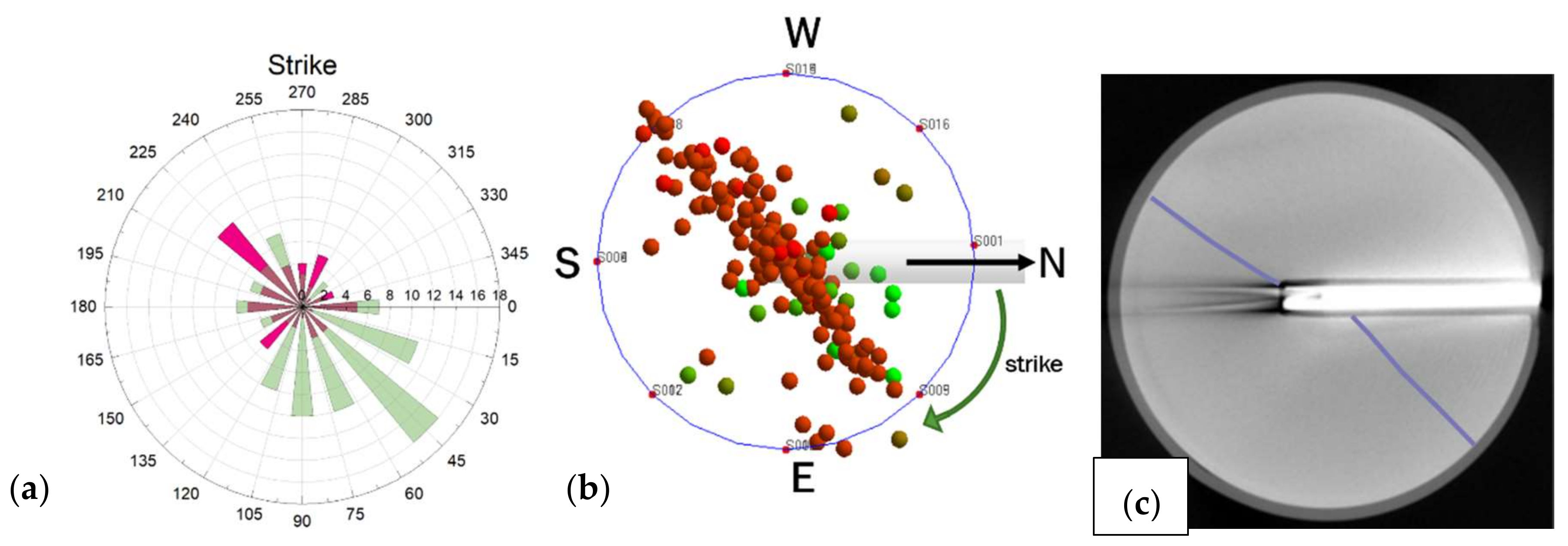
Figure 24a demonstrates the distribution of angles (strike) corresponding to the direction of the line formed by the intersection of the fault plane and the direction to the north. The prevailing direction of the fault plane deviation is 40° for one family of solutions and 225° for another one, which fully corresponds to the results of localization of AE events and CT scan. The plane of the fracture is parallel to the vertical stress and shows that the AE events were formed by small dislocations aligned with the plane of the main hydraulic fracture (Figure 24b,c).

4. Discussion

Experimental results of the sandstone sample (with 100,000 cP injection fluid) showed that the fracture was initiated around two minutes prior to the wellbore pressure reaching its peak (breakdown). The analysis of AE localization demonstrated that the breakdown moment, in turn, corresponds to the moment the fracture reaches the side surface of the cylindrical sample. Initially, the hydraulic fracture was close to a pancake-like shape, and it was growing symmetrically from the injection point at a speed of about 0.45 mm/s. After it reached the cylindrical surface, the fracture kept growing vertically at an increased speed of around 3 mm/s. Analysis of radial strain and injected volume allows for estimating the aperture of a hydraulic fracture at this moment.
Analysis of the tested shale-like rock samples (with 46 cP injection fluid) showed that in four samples out of six, the initiation of a hydraulic fracture was registered by the AE technique earlier than the moment of recording the maximum pressure in the wellbore (the breakdown moment). However, the initiation was observed fractions of a second before the breakdown moment in shale-like rocks instead of two minutes in the case of the sandstone sample. In two samples (ARE-8R1 and ARE-1R1), a hydraulic fracture initiation was observed almost simultaneously with the recording of the maximum pressure. Moreover, the localization of the AE signals showed that in these two samples, hydraulic fracture growth was initially observed only in one direction: from the wellbore to the upper surface of the sample. At the same time, the propagation speed of hydraulic fracturing when testing shale-like samples was in the range of 25–225 mm/s, that is, significantly higher than 0.45 mm/s observed during the testing of the sandstone. We attributed such a significant difference in the behavior of a hydraulic fracture in sandstone and shale-like formations to the influence of the viscosity of the injected fluid. A low-viscosity fluid can penetrate a hydraulic fracture almost immediately after crack initiation. In contrast, a viscous fluid requires sufficient crack opening, and only after that can a viscous fluid penetrate the crack. These results are in good agreement with the results of [14,43], which showed that the growth rate of hydraulic fracturing could change a thousand times with a significant change in the viscosity of the fluid with the same injection rate. In addition, in [14,43], when injecting a low-viscosity fluid, there was also a hydraulic fracture propagation observed in one direction, similar to the results of the ARE-8R1 and ARE-1R1 studies obtained in this work.
The comparison of independent measurements of injection parameters and AE allowed us to conclude that the moment when a hydraulic fracture approaches the sample surface is in good agreement with the moment of recording the minimum value of the derivative of the fluid pressure in the wellbore. Thus, these studies have shown that the registration of AE signals allows for determining the moment of initiation of a hydraulic fracture. The moment of recording the minimum derivative of the pressure in the wellbore allows for determining the moment when the fracture reaches the cylindrical surface of the specimen. Therefore, the combination of AE and injection parameters allows us to study the dynamics of the propagation of hydraulic fracturing.
Comparing the fracture propagation speeds with the pressure drop rates, one can see that samples ARE-3R1 and ARE-8R1 have the highest speeds of hydraulic fracture propagation, 225 and 200 mm/s respectively, and these two samples had the fastest wellbore pressure drops (165–192 MPa/s, Table 4). Both samples had a dense texture, a high degree of consolidation, and a siliceous component, which led to their rapid and brittle disruption with a characteristic uneven and rough hydraulic fracture surface. The lowest speed of hydraulic fracture propagation (30 mm/s) was observed in the sample ARE-4R4, and at the same time, this sample demonstrated the slowest wellbore pressure drop (30 MPa/s, Table 4). This can be explained by the fact that this sample contained multiple comparatively small organic grains (considerably smaller in size than the specimen) and HF penetrated most of the small particles, which is also reflected in the high portion of CLVD component, resulting in a relatively straight HF path. It should be emphasized that in all six tests, the fluid injection rate was the same, equal to 5 mL/min. Therefore, we explained the differences in the dynamics of the hydraulic fracture propagation by the difference in the structure of the studied samples, by the presence of inclusions, and pre-existing cracks in them, indicated by X-ray CT images (Figure 18 and Figure 19e,g).
The experimental results of the ARE-4R4 and ARE-8R1 samples were most often outside of the general trend valid for the remaining samples. First of all, it is due to their heterogeneity. Figure 25 shows vertical slices of X-ray computed tomography of the ARE-4R4 sample. It is easy to notice the existence of many small white inclusions, which are very dense. Additionally, there are two large dark inclusions (small density) on the slice with uneven, sharp edges. The lithological description suggests that this sample is detrital-clastic. Note the presence of a sub-horizontal crack located almost in the center of the sample (orange dashed line). Apparently, large and angular inclusions are potential stress concentrators, causing a slowing down of the hydraulic fracture propagation in the vicinity of inclusions, significantly changing the dynamics of hydraulic fracture propagation.
Sections of X-ray computed tomography of the ARE-8R1 sample, whose behavior is also different from most of the samples, are shown in Figure 26. The upper part of the sample has a significant interlayer, presumably containing some organic material. The thickness of the interlayer is estimated to be 1/6 of the sample length (approximately 12.6 mm). As can be seen on the right slices, it influences the geometry of the hydraulic fracture. There is a sub-horizontal fracture (left slice) below the interlayer that existed in the sample before the experiment.

5. Conclusions

A new methodology for rock sample hydraulic fracturing (HF) under pseudo-triaxial loading conditions representing stressed reservoir conditions was developed. This methodology was tested by creating HF in a sandstone sample by injecting a high-viscosity (100,000 cP) silicone oil. The dynamics of HF propagation were monitored using a combination of three independent experimental techniques. The AE technique indicated the moments of HF initiation, the beginning of HF growth, and its exit to the cylindrical surface of the sample, as well as allowed us to estimate the speed of HF growth. The second technique allowed us to measure the circumferential deformation of the specimen using a chain installed in the central part of the sample. The third technique allowed us to calculate the fraction of fluid volume that penetrated the HF. Testing the sandstone sample showed that a combination of the results of these three independent techniques allowed us to monitor the dynamics of hydraulic fracture propagation, providing HF parameters that could hardly be measured directly in the field conditions.
After preliminary sandstone testing, the developed methodology was applied to study the dynamics of HF propagation during the injection of 46 cP silicone oil in six shale-like core samples provided by RITEK LLC. The main objectives of these tests were: (a) to study the relationship between HF parameters and the geomechanical characteristics of the rock and (b) to study the influence of rock fabric on the dynamics of HF propagation. It was found that initiation of HF during injection of the low-viscosity fluid was observed in all shale-like samples either a fraction of a second prior to the breakdown moment (the moment of maximum wellbore pressure recording) or simultaneously with the breakdown moment. When a low-viscosity fluid was injected into shale-like samples, the HF growth speed was significantly higher than when viscous fluid was injected into the sandstone sample. We explained this finding by a strong influence of fluid viscosity on HF dynamics, and the results of our study are entirely consistent with those published earlier in [19,22].
We have found that the tensile strength of the sample and the speed of HF growth correlated linearly with the breakdown pressure. However, samples ARE-3R1, ARE-4R4, and ARE-8R1 demonstrated some deviation from the general trend, which is explained by the influence of the sample fabric, the presence of natural cracks, and structural inclusions in the samples. The moment tensor inversion (MTI) analysis of the AE signals showed a high portion of shear and compressive components during the interval of HF propagation before the HF appeared on the sample surface. This was explained by the creation of small-sized microcracks with a small aperture. During the time interval after HF reached the cylindrical surface of the sample, the tensile component of the MTI (called CLVD), characterizing the opening of hydraulic fracture, became dominant. The direction of HF opening based on MTI analysis was found to be in good agreement with the orientation of macroscopic crack, directly determined after the testing by X-ray CT. Taking into account the impossibility of proppant injection into shear cracks, the results of MTI can be applied to analyze the success of proppant delivery into the created hydraulic fracture. Thus, the results obtained from the series of laboratory tests on shale-like samples can be used for verification of the models of HF growth and for the interpretation of data obtained in the field.

Author Contributions

Conceptualization, methodology, M.B. and S.S.; software, M.B., S.S. and E.F.; validation, E.F.; formal analysis, investigation, M.B., A.S. and S.S.; data curation, V.S.; resources, funding acquisition, T.S.; writing—original draft preparation, M.B.; writing—review and editing, M.B., A.S. and S.S.; visualization, M.B.; supervision, project administration S.S. All authors have read and agreed to the published version of the manuscript.

Funding

This work was supported by the Ministry of Science and Higher Education of the Russian Federation under agreement No. 075-10-2020-119 within the framework of the development program for a world-class Research Center. Additionally, this work received external funding from RITEK LLC.

Data Availability Statement

Restrictions apply to the availability of these data. Data were obtained with financial support from RITEK LLC and are available from the corresponding author with the permission of RITEK LLC.

Acknowledgments

The authors would like to thank Alexander Burukhin and Andrey Morkovkin for X-ray CT preparation, Vladimir Efstadiu for sample preparation, Elena Kozlova for preparing TOC results, and Natalia Bogdanovich, Elizaveta Idrisova, and Tagir Karamov of Skoltech for help in preparing a litho-stratigraphic column. The revision comments and discussion with Mikhail Spasennykh of Skoltech are greatly acknowledged. The authors thank helpful comments of three anonymous reviewers. The authors also thank RITEK LLC for support of the presented research and granting permission to publish results.

Conflicts of Interest

The authors declare no conflict of interest.

References

  1. Soeder, D.J. The successful development of gas and oil resources from shales in North America. J. Pet. Sci. Eng. 2018, 163, 399–420. [Google Scholar] [CrossRef]
  2. Henderson, J. Tight Oil Developments in Russia; Oxford Institute for Energy Studies: Oxford, UK, 2013. [Google Scholar]
  3. Denney, D. Thirty Years of Gas-Shale Fracturing: What Have We Learned? J. Pet. Technol. 2010, 62, 88–90. [Google Scholar] [CrossRef]
  4. Yi, P.; Haifeng, F.; Mingyue, C.; Yunzhi, L.; Yun, X.; Yongjun, L.; Xing, W.; Yonghui, W. What Do Hydraulic Fractures Look Like in Different Types of Reservoirs: Implications from a Series of Large-Scale Polyaxial Hydraulic Fracturing Experiments from Conventional to Unconventional. In Proceedings of the 7th Unconventional Resources Technology Conference, Denver, CO, USA, 22–24 July 2019; pp. 1–14. [Google Scholar] [CrossRef]
  5. Heng, S.; Li, X.; Zhang, X.; Li, Z. Mechanisms for the control of the complex propagation behaviour of hydraulic fractures in shale. J. Pet. Sci. Eng. 2021, 200, 108417. [Google Scholar] [CrossRef]
  6. Strpić, K.; Miličević, M.; Kurevija, T. Development of Tight Oil Resources in USA: Profitability of Exploitation and Effect of Macroeconomic Indicators in Volatile Oil Price Environment. Rud. Geološko Naft. Zb. 2017, 32, 23–33. [Google Scholar] [CrossRef] [Green Version]
  7. Guo, F.; Morgenstern, N.; Scott, J. An experimental investigation into hydraulic fracture propagation—Part 2. Single well tests. Int. J. Rock Mech. Min. Sci. Géoméch. Abstr. 1993, 30, 189–202. [Google Scholar] [CrossRef]
  8. Zoback, M.; Rummel, F.; Jung, R.; Raleigh, C. Laboratory hydraulic fracturing experiments in intact and pre-fractured rock. Int. J. Rock Mech. Min. Sci. Géoméch. Abstr. 1977, 14, 49–58. [Google Scholar] [CrossRef]
  9. Patel, S.; Sondergeld, C.; Rai, C. Laboratory studies of hydraulic fracturing by cyclic injection. Int. J. Rock Mech. Min. Sci. 2017, 95, 8–15. [Google Scholar] [CrossRef]
  10. Akrad, O.M.; Miskimins, J.L.; Prasad, M. The Effects of Fracturing Fluids on Shale Rock Mechanical Properties and Proppant Embedment. Days 2011, 3, 2245–2256. [Google Scholar] [CrossRef] [Green Version]
  11. Zhang, J.; Kamenov, A.; Zhu, D.; Hill, A.D. Laboratory Measurement of Hydraulic-Fracture Conductivities in the Barnett Shale. SPE Prod. Oper. 2014, 29, 216–227. [Google Scholar] [CrossRef]
  12. Fisher, K.; Warpinski, N. Hydraulic-Fracture-Height Growth: Real Data. SPE Prod. Oper. 2012, 27, 8–19. [Google Scholar] [CrossRef]
  13. Liang, Y.; Cheng, Y.; Zou, Q.; Wang, W.; Ma, Y.; Li, Q. Response characteristics of coal subjected to hydraulic fracturing: An evaluation based on real-time monitoring of borehole strain and acoustic emission. J. Nat. Gas Sci. Eng. 2017, 38, 402–411. [Google Scholar] [CrossRef]
  14. Stanchits, S.; Burghardt, J.; Surdi, A. Hydraulic Fracturing of Heterogeneous Rock Monitored by Acoustic Emission. Rock Mech. Rock Eng. 2015, 48, 2513–2527. [Google Scholar] [CrossRef]
  15. Chen, Y.; Nagaya, Y.; Ishida, T. Observations of Fractures Induced by Hydraulic Fracturing in Anisotropic Granite. Rock Mech. Rock Eng. 2015, 48, 1455–1461. [Google Scholar] [CrossRef]
  16. Stoeckhert, F.; Molenda, M.; Brenne, S.; Alber, M. Fracture propagation in sandstone and slate–Laboratory experiments, acoustic emissions and fracture mechanics. J. Rock Mech. Geotech. Eng. 2015, 7, 237–249. [Google Scholar] [CrossRef] [Green Version]
  17. Kolawole, O.; Ispas, I. Interaction between hydraulic fractures and natural fractures: Current status and prospective directions. J. Pet. Explor. Prod. Technol. 2020, 10, 1613–1634. [Google Scholar] [CrossRef] [Green Version]
  18. Li, Q.; Xing, H.; Liu, J.; Liu, X. A review on hydraulic fracturing of unconventional reservoir. Petroleum 2015, 1, 8–15. [Google Scholar] [CrossRef] [Green Version]
  19. Stanchits, S.; Surdi, A.; Gathogo, P.; Edelman, E.; Suarez-Rivera, R. Onset of Hydraulic Fracture Initiation Monitored by Acoustic Emission and Volumetric Deformation Measurements. Rock Mech. Rock Eng. 2014, 47, 1521–1532. [Google Scholar] [CrossRef]
  20. Wasantha, P.L.P.; Ranjith, P.; Zhang, Q.; Xu, T. Do joint geometrical properties influence the fracturing behaviour of jointed rock? An investigation through joint orientation. Géoméch. Geophys. Geo-energy Geo-resour. 2015, 1, 3–14. [Google Scholar] [CrossRef] [Green Version]
  21. Huang, B.; Li, P. Experimental Investigation on the Basic Law of the Fracture Spatial Morphology for Water Pressure Blasting in a Drillhole Under True Triaxial Stress. Rock Mech. Rock Eng. 2015, 48, 1699–1709. [Google Scholar] [CrossRef]
  22. Zhu, Q.; Feng, Y.; Cai, M.; Liu, J.; Wang, H. Interpretation of the extent of hydraulic fracturing for rockburst prevention using microseismic monitoring data. J. Nat. Gas Sci. Eng. 2017, 38, 107–119. [Google Scholar] [CrossRef]
  23. Chen, L.-H.; Chen, W.-C.; Chen, Y.-C.; Benyamin, L.; Li, A.-J. Investigation of Hydraulic Fracture Propagation Using a Post-Peak Control System Coupled with Acoustic Emission. Rock Mech. Rock Eng. 2014, 48, 1233–1248. [Google Scholar] [CrossRef]
  24. Li, B.Q.; da Silva, B.G.; Einstein, H. Laboratory hydraulic fracturing of granite: Acoustic emission observations and interpretation. Eng. Fract. Mech. 2019, 209, 200–220. [Google Scholar] [CrossRef]
  25. Zhai, H.; Chang, X.; Wang, Y.; Lei, X.; Xue, Z. Analysis of acoustic emission events induced during stress unloading of a hydraulic fractured Longmaxi shale sample. J. Pet. Sci. Eng. 2020, 189, 106990. [Google Scholar] [CrossRef]
  26. Lavrusevich, A.; Abene, A.; Lavrusevich, I. Geoecological aspects of technogenic impact on the territory of raw materials production for construction. MATEC Web Conf. 2019, 265, 06013. [Google Scholar] [CrossRef]
  27. Stanchits, S.A. Anisotropic Changes in P-Wave Velocity and Attenuation during Deformation and Fluid Infiltration of Granite. Bull. Seism. Soc. Am. 2003, 93, 1803–1822. [Google Scholar] [CrossRef]
  28. Stanchits, S.; Vinciguerra, S.; Dresen, G. Ultrasonic Velocities, Acoustic Emission Characteristics and Crack Damage of Basalt and Granite. Pure Appl. Geophys. PAGEOPH 2006, 163, 975–994. [Google Scholar] [CrossRef]
  29. Stanchits, S.; Mayr, S.; Shapiro, S.; Dresen, G. Fracturing of porous rock induced by fluid injection. Tectonophysics 2011, 503, 129–145. [Google Scholar] [CrossRef]
  30. Leonard, M.; Kennett, B. Multi-component autoregressive techniques for the analysis of seismograms. Phys. Earth Planet. Inter. 1999, 113, 247–263. [Google Scholar] [CrossRef]
  31. Nelder, J.A.; Mead, R. A Simplex Method for Function Minimization. Comput. J. 1965, 7, 308–313. [Google Scholar] [CrossRef]
  32. Punanova, S.A.; Chakhmakhchev, V.A.; Agafonova, Z.G.; Kukushkina, Z.P.; Gordadze, T.I. Oil Geochemistry of Subsalt Deposits of the Western Caspian Foundation, Geol. Oil Gas, No. 7, 1996. Available online: http://www.geolib.ru/OilGasGeo/1996/07/Stat/stat05.html (accessed on 14 July 2021). (In Russian).
  33. Ostroukhov, S.B.; Tsygankova, V.A.; Popova, P.F.; Kruk, P.N. On the genesis of oil and gas bearing subsalt lower artinskian deposits of the western Caspian. Subsurf. Resour. Volga Casp. Reg. 2019. [Google Scholar] [CrossRef]
  34. Mikhal’kova, V.N.; Brazhnikov, O.G.; Beresfetskaya, A.M. Selecting the Trends of Searching for Oil and Gas Deposits within the Western Part of the Precaspian Depression, Geol. Oil Gas, No. 5, 1990. Available online: http://geolib.narod.ru/Journals/OilGasGeo/1990/05/Stat/03/stat03.html (accessed on 14 July 2021). (In Russian).
  35. Gabnasyrov, A.V.; Lyadova, N.A.; Putilov, I.S.; Solovyev, S.I. Domanik Shale Oil: Unlocking Potential. In Proceedings of the All Days, Moscow, Russia, 24–26 October 2016; Society of Petroleum Engineers (SPE): Moscow, Russia, 2016; pp. 622–637. [Google Scholar]
  36. Lockner, D.A.; Byerlee, J.D.; Kuksenko, V. Observations of quasistatic fault growth from acoustic emissions. In International Geophysics; Academic Press: Cambridge, MA, USA, 1992; Volume 51, pp. 3–31. [Google Scholar]
  37. Durney, D.W. An application of normal mode theory to the retrieval of structural parameters and source mechanisms from seismic spectra. Philos. Trans. R. Soc. London. Ser. A Math. Phys. Sci. 1975, 278, 187–269. [Google Scholar] [CrossRef]
  38. Jia, Q.S.; Wong, R.C.K.; Eaton, D.W.; Eyre, T.S. Investigating fracture growth and source mechanisms in shale using acoustic emission technique. Proceeding of the 52nd U.S. Rock Mechanics/Geomechanic Symposium, Seattle, WA, USA, 17–20 June 2018. [Google Scholar]
  39. InSite Seismic Processor: Technical Appendix, 2021, Applied Seismology Consultants. Available online: https://www.appliedseismology.co.uk/support/resources/ (accessed on 14 July 2021).
  40. Hudson, J.A.; Pearce, R.G.; Rogers, R.M. Source type plot for inversion of the moment tensor. J. Geophys. Res. Space Phys. 1989, 94, 765–774. [Google Scholar] [CrossRef] [Green Version]
  41. Chapman, C.H.; Leaney, W.S. A new moment-tensor decomposition for seismic events in anisotropic media. Geophys. J. Int. 2011, 188, 343–370. [Google Scholar] [CrossRef] [Green Version]
  42. Aki, K.; Richards, P.G. Quantitative Seismology, 2nd ed.; University Science Books: Sausalito, CA, USA, 2009. [Google Scholar]
  43. Stanchits, S.; Surdi, A.; Edelman, E.; Suarez-Rivera, R. Acoustic Emission and Ultrasonic Transmission Monitoring of Hydraulic Fracture Initiation and Growth in Rock Samples. In Proceeding of the 46th U.S. Rock Mechanics/Geomechanics Symposium, Chicago, IL, USA, 24–27 June 2012; pp. 12–15. [Google Scholar]
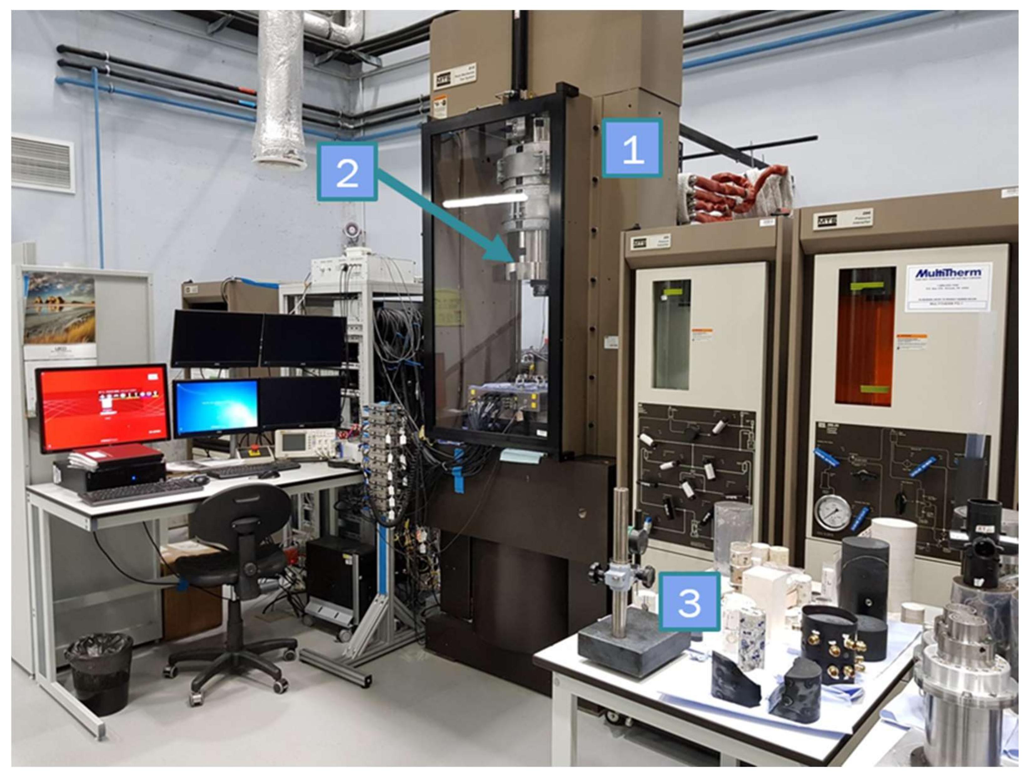
Figure 1. General view of the MTS 815 servo-hydraulic unit in the laboratory. 1: Loading frame, 2: confining pressure chamber, 3: core specimens.
Geosciences 11 00292 g001
Figure 2. Schematic map of the quarries for the extraction of raw materials for the building industry in the Moscow region [26] and sandstone specimen before the experiment.
Geosciences 11 00292 g002
Figure 3. A sandstone specimen with a transverse extensometer (1) installed, AE sensors (2) glued onto the cylindrical surface, and a tube (3) glued into the wellbore. (a) Specimen before fracturing, and (b) specimen after fracturing.
Geosciences 11 00292 g003
Figure 4. Projected sample surface of the sandstone MSS-401 with positions of 18 AE sensors and borehole as a function of azimuth and vertical coordinate Z.
Geosciences 11 00292 g004
Figure 5. Projected sample surface of the shale-like rocks with positions of 18 AE sensors and borehole as a function of azimuth and vertical coordinate Z.
Geosciences 11 00292 g005
Figure 6. Schematic location map of the superdeep well, where layers of the Artiskian Stage have been studied.
Geosciences 11 00292 g006
Figure 7. A generalized litho-stratigraphic column (refer to the legend), total organic carbon concentration, lithological description, and geomechanical characteristics of the members.
Geosciences 11 00292 g007
Figure 8. Installation diagram of the transverse extensometer (1) and brass housings (2) with acoustic sensors on the sample.
Geosciences 11 00292 g008
Figure 9. Photos of specimen ARE-2R6 before the test with mounted AE sensors and casing glued into the wellbore.
Geosciences 11 00292 g009
Figure 10. (a) pressure of the injected fluid (red) and the total number of localized AE signals (purple), (b) rate of pressure change in the wellbore, (c) change in the length of the chain transverse extensometer of the sample (green) and the volume of fluid injected into the hydraulic fracture (magenta), (d) amplitudes of AE signals, (e) vertical coordinates of the localized AE signals along the hydraulic fracture plane. All parameters are plotted versus the time of testing the sandstone sample.
Geosciences 11 00292 g010
Figure 11. (ac) Three orthogonal projections of the coordinates of the AE signals, (e) parameters recorded up to the moment of the maximum wellbore pressure. The color of the dots corresponds to the recording time of the AE signals, according to the color scale presented in the lower part of Figure (e). (fh) Three orthogonal projections of the normalized density of AE events. (d,i) X-ray images, taken in cross-section of the sample at heights of 70 and 65 mm, respectively.
Geosciences 11 00292 g011
Figure 12. (a,f) Pressure of the injected fluid (red) and total number of localized AE signals (purple), (b,g) rate of wellbore pressure change, (c,h) change in the length of the chain of the transverse extensometer (green) and volume of fluid injected into the hydraulic fracture (magenta), (d,i) amplitude of AE signals, (e,j) vertical coordinates of the localized AE signals. The left column shows ARE-2R6 results, and the right column shows ARE-4R4 results. All parameters are plotted versus sample testing time.
Geosciences 11 00292 g012
Figure 13. (a,f) Pressure of the injected fluid (red) and total number of localized AE signals (purple), (b,g) rate of wellbore pressure change, (c,h) change in the length of the chain of the transverse extensometer (green) and volume of fluid into the hydraulic fracture (magenta), (d,i) amplitude of AE signals, (e,j) vertical coordinates of the localized AE signals. The left column shows ARE-3R1 results, and the right column shows ARE-8R1 results. All parameters are plotted versus sample testing time.
Geosciences 11 00292 g013
Figure 14. (a,f) Pressure of the injected fluid (red) and total number of localized AE signals (purple), (b,g) rate of wellbore pressure change, (c,h) change in the length of the chain of the transverse extensometer (green) and volume of fluid injected into the hydraulic fracture (magenta), (d,i) amplitude of AE signals, (e,j) vertical coordinates of the localized AE signals. The left column shows ARE-1R1 results, and the right column shows ARE-1R2 results. All parameters are plotted versus sample testing time.
Geosciences 11 00292 g014
Figure 15. Tensile strength (TXTR) versus fracturing fluid pressure.
Geosciences 11 00292 g015
Figure 16. Changes in chain length (a), breakdown pressure (b), and fracture propagation speed (c) versus the volumes of fluid entered into the fracture, measured at the moments of the beginning of fluid leaking out of the rock specimen.
Geosciences 11 00292 g016
Figure 17. Changes in the chain length (a) and fracture propagation speed (b) versus breakdown pressure.
Geosciences 11 00292 g017
Figure 18. Results of X-ray computed tomography (vertical projection) of samples after hydraulic fracturing tests at a lateral pressure of 27.4 MPa.
Geosciences 11 00292 g018
Figure 19. Location of AE hypocenters and corresponding CT-scans for the sample ARE-4R4 ((a)—pressure of the injected fluid (blue), change in the chain length of the transverse extensometer (green) and location magnitude of AEs (light blue) against time; (b,c)—top view; (d,e)—EW projection; (f,g)—NS projection). The colors of the circles correspond to the timescale presented below graph (c).
Geosciences 11 00292 g019
Figure 20. Distribution of AE hypocenters during four time-intervals for the sample ARE-4R4. (a) fracture initiation, (b) breakdown moment, (c) moment of fluid leakage, (d) the end of the experiment. Black triangles show the positions of sensors and colored circles show the coordinates of localized AE signals.
Geosciences 11 00292 g020
Figure 21. Localization of AE signals in three orthogonal projections with corresponding sections of computed tomography and time history of measured geomechanical parameters for the ARE-8R1 sample. (a) X-ray image of the sample (vertical projection); (bd) three orthogonal projections of the coordinates of the AE signals; (e) X-ray image, taken in cross-section of the sample at height of 42 mm; (f) parameters recorded after the moment of the maximum wellbore pressure; the color of the dots corresponds to the recording time of the AE signals, according to the color scale presented in the lower part of Figure (f).
Geosciences 11 00292 g021
Figure 22. Hudson diagram showing the distribution of crack formation mechanisms for the ARE-4R4 sample (a) at the moment of fracture formation, (b) maximum fluid pressure, and (c) after the crack reaches the sample surface.
Geosciences 11 00292 g022
Figure 23. (a) Hudson diagram for the sample ARE-8R1 (left) and distribution of components of crack formation mechanisms (ISO—isotropic component, CLVD—tensile or compressive component, DC—shear component) from the moment of pressure maximum (b) before the fracture reaches the sample surface, and (c) after the fracture emerges on the sample surface.
Geosciences 11 00292 g023
Figure 24. Fracture geometry from the decomposition of the moment tensor solutions for the ARE-8R1 sample. (a) Distribution of strikes, (b) location of AE hypocenters (top view), and (c) CT-scan (top view).
Geosciences 11 00292 g024
Figure 25. Vertical projection of X-ray CT of the sample ARE-4R4 after the experiment, showing lithological heterogeneity (presence of inclusions).
Geosciences 11 00292 g025
Figure 26. Vertical projection of X-ray CT of the sample ARE-8R1 after the experiment, showing lithological heterogeneity (presence of inclusions).
Geosciences 11 00292 g026
Table 1. MSS-401 specimen properties.
SampleLength, mmDiameter, mmDensity, g/cm3Porosity, %Gas Permeability, mDYoung’s Modulus E, GPaPoisson’s Ratio
MSS-401107.9949.222.543.651.5972.930.15
Table 2. Generalized results of geomechanical studies.
Sample Number ARE-1R1ARE-1R2ARE-2R6ARE-3R1ARE-4R4ARE-8R1
Sampling depthm5781.285780.185787.065847.875861.15873.64
Lengthmm108.7887.35110.1096.51104.0275.76
Diametermm49.0849.2248.9849.3049.1149.20
Length/Diameter 2.221.772.251.962.121.54
Weightg560.23447.60538.60508.10532.70387.24
Volumecm3205.80166.20207.45184.23197.04144.03
Densityg/cm32.722.692.602.762.702.69
Average effective gas
permeability
mD4.854.850.430.610.830.42
Average porosity%1.951.953.451.982.052.13
Uniaxial compressive strength (UCS)MPa86.886.878.1397.4121.2247.1
Young’s modulus EGPa51.1451.1446.4879.0052.7655.15
Poisson’s ratio ν 0.250.250.220.170.130.10
Table 3. Vertical and horizontal components of the longitudinal wave propagation velocities, PV and PH, correspondingly. AP—anisotropy of longitudinal wave, calculated as A P = P V P H P V .
SampleARE-1R1ARE-1R2ARE-2R6ARE-3R1ARE-4R4ARE-8R1
PV, m/s457452274374592259285167
PH, m/s500852414920557256304973
AP, %−9.4−0.27−12.55.953.7
Table 4. Brief description of experimental results.
SampleARE-1R1ARE-1R2ARE-2R6ARE-3R1ARE-4R4ARE-8R1MSS-401
Tensile strength (TXTR), MPa7.657.6510.2018.558.6010.40
Breakdown pressure, MPa51.0852.1257.3567.6349.7663.6642.50
Change of the chain length at the time of fluid exit, μm11461851827335425
Fluid volume entered into the fracture, mL0.640.390.370.220.650.290.11
Fracture propagation speed, mm/s120115125225252000.45–3
Fluid injection rate, mL/min5555550.5
Rate of wellbore pressure drop,
MPa/s
−31−43−91−165−30−192−0.61
Fluid viscosity, cP464646464646100,000
Z coordinate of the wellbore, mm73.55571607038.570
Sigma 1, MPa54.8054.8054.8054.8054.8054.8016.60
Sigma 3, MPa27.3827.3827.3827.3827.3827.380.27
Publisher’s Note: MDPI stays neutral with regard to jurisdictional claims in published maps and institutional affiliations.