1. Introduction
Although a single rockfall impacts only a small area, the possible extension of this natural hazard threatens larger areas, especially along communication routes in mountainous areas, with the risk of high damage and economic and social losses. Flexible rockfall protection systems are an effective and efficient tool against rockfalls with energy levels between 100 kJ to up to 10,000 kJ. Despite the fact that a block with a weight of 25 tons travelling at more than 100 km/h is a dangerous hazard, it is almost unthinkable that a light fence structure can successfully hold-up such a block. How can you trust a system to provide the necessary protection to buildings and secure the infrastructure? Every engineer is further confronted with questions, like: does a barrier fit my project? How do I know whether my demands on the barrier are correct? How can I check an effective approach and whom do I talk to?
This document provides some insight on how to judge the capability, reliability and trustworthiness of a rockfall protection system. These aspects are relevant not just for the people living or travelling alongside these flexible protection systems but also for the people in charge of selecting a suitable protection system. Being confronted with preparing quotations for different protection systems, it is essential to choose the appropriate barrier for the intended use.
This article focuses on three specific strategies on how to build confidence and increase trust in regard to defining the right barrier construction, what proper testing measures and certifications are necessary, and how to assess properly adaptions of standard barrier systems. It is obvious that detailing every single one of these topics will become very extensive, and any further illustrative examples would require a separate presentation. This article, however, will provide an overview on the topics with specific references to corresponding overviews in literature. Most of the references given are public records and easily accessible.
2. Full-Scale Testing
The clearest proof for a correctly functioning rock barrier is a full-scale test. Since the very first setups of flexible rockfall protection systems, it is still the only method that provides the necessary security and it is widely accepted. Duffy and Glover [
1] compiled an overview on testing procedures used since the early 1960s. At that time, rockfall protection barriers were tested on natural slopes with natural rock blocks being released upslope. This method provides a most natural loading of a rockfall fence. However, this test is also risky because it does not account for the possibility of the barrier is not being hit at all, being hit in a non-favourable location, or being hit with an unwanted impact energy. For these reasons, the next level in rockfall barrier testing was reached by accelerating the impacting block with forestry cable cars. This allowed a controlled acceleration of the block and—with a well-timed unleash of the block—a predictable impact on the barrier could be assessed. Since the late 1990s, the established standard testing procedure uses a crane to position the block vertically above a barrier that was installed perpendicular to a vertical wall face. The block is dropped and impacts the barrier with a precision of a few centimetres. This procedure is very accurate and reproducible. However, some test sites with ropeway-guided blocks are still in use. Other sites even create an impact of a horizontally accelerated block into a vertical barrier. Both Heiss [
2] and Volkwein [
3] compared results between vertical and inclined testing, concluding that—in principle—both common procedures can impact a rockfall protection barrier as intended. The performance of the barriers did differ with respect to distinct results: as an example, the residual height after the test is 10% smaller for a vertically tested barrier and the energy absorbing elements are loaded up to 50% more.
Natural field-testing is also a proven method for non-standard load cases, such as a tree fall, for example. As soon as engineers, designers, or their representatives are confronted with test results, several aspects need to be considered: it is important to present a clear test description, a documented structural system setup, the proper measurement procedures, external supervision, and testing reports, to name just a few.
Another critical aspect, which was also pointed out by Volkwein et al. [
4], is that any standardisation of barrier testing neglects the variability under (natural) field conditions, caused by the differences in block shape, rotational movements, impact speed, or impact location. In particular, certain impact locations have the potential to harm a barrier more than the tested standard load cases or can even cause the barrier to fail all together. Further, if small blocks with high impact velocities are expected, the mesh might suffer from puncturing loads, as studies by Buzzi et al. [
5] show. Therefore, the newest trend in rockfall barrier testing goes back to its original form and tests are conducted with barriers on a natural slope as, e.g., brought by Wendeler et al. [
6].
3. Standardisation
The benefit of precise and repeatable testing procedures is that testing standards can be defined. For example, a rockfall event was quantified by the use of its kinetic energy level at the impact: 3000 kJ corresponds to a block with a weight of 9600 kg at an impact velocity of 25 m/s = 90 km/h. This approach neglects that up to 40% of the kinetic energy might be rotational kinetic energy. This assumes that a straight moving, non-rotating block has the highest and most harmful energy concentration developed for the barrier.
Based on the kinetic energy, the rockfall barriers were put into classes, such as 100, 250, 500, 1000, 2000, 3000, 5000, 8000, 10,000 kJ. They allow the user or its representative to define clearly their needs when asking the manufacturers for quotations. The energy classes above can be achieved by either varying the block’s mass or its impact velocity. In Switzerland, a definition introduced by Gerber [
7], sets the standard impact velocity to 25 m/s and uses a variation of the impacting weight. This approach was based on the conclusion that the mass of a potential rockfall block in the field can be determined more easily than its expected impact velocity. The standard impact velocity of 25 m/s is more or less the maximum block velocity that has been observed in the Alps by Gerber [
8]. This, in return, means that, with a determined block mass and a maximum possible impact velocity, the expected impact energy will always be on the safe side.
4. Certification
Parallel to the standardisation of the testing procedures, certificates were issued testifying a barrier’s energy retention capacity. The first of its kind was the Swiss guideline (Gerber, 2001). This guideline defined the testing procedures that a flexible barrier is mounted to a vertical rock face and a test specimen vertically falls into the barrier. This allows an evaluation of the maximum level and service level energy retention capacity, the loads acting on the anchorage, the braking distance, the residual barrier height, the performance for small and medium-sized rockfall events, and the necessary maintenance works. In the European Union the guideline for technical approval of falling rock protection kits ETAG 027 [
9] was established seven years later with an evaluation scheme similar to the Swiss guideline. The defined certification standards are still valid today and were precisely transferred to the follow-up European Assessment Document EAD 340059-00-0106 [
10] that replaces the ETAG 027. A barrier approved to the European regulations can be CE marked, a process that has been described by, e.g., Kohlmaier [
11], Volkwein et al. [
4], or Roduner [
12].
This certification is a huge benefit for society. The users usually do not know exactly what performance standard they can expect from a rockfall protection system. A certificate (in this case CE mark) not only warrants the characteristics of a barrier but also implies a continuous surveillance of the manufacturer in regard to quality control, documented internal processes, and retrace-ability. This covers mainly two aspects:
every manufacturing process is described clearly to guarantee continuous quality for all components.
in case that a quality issue is detected (e.g., malfunction of a single component in the field), it can be backtracked to where the error happened. The quality management then can take the necessary measures both to handle the current case (replacement or even a product recall) and to avoid such an error in future.
The aforementioned changes from ETAG 027 to EAD 340059-00-0106 in 2018 did, however, imply some main changes: today, an official assessment (ETA = European Technical Assessment) only confirms that the protection barrier fulfils the essential characteristics according to the so-called declaration of performance (DoP). This has the following consequences for the users as highlighted in Volkwein et al. [
4]:
there are several EADs a product can be certified after. This means that, if someone purchased an assessed or CE marked barrier, it has to be checked carefully whether the underlying EAD is the correct one for the intended use. A simple check of whether a system has a valid ETA or CE mark is not enough.
if the ETA or CE mark belongs to the correct EAD, it further has to be checked whether the manufacturer of the construction product declares in its declaration of performance all the essential characteristics listed in the EAD. Theoretically, construction products can be successfully assessed even if the manufacturer declares only some of the essential characteristics.
The new ETA lists only certain (measured) test results as essential characteristics. Their application to planned field installations must also be handled.
How is the braking distance defined in the ETA? Is it defined relative to a position on the ground or on the net? This influences where the system has to be placed in the field to stop impacting blocks early enough.
Does the reference slope of the system correspond to the inclination of the slope in the field? If not, how should, e.g., sag or braking distance be adjusted?
Are there likely to be special load cases, e.g., an impact into a lateral field, that were not assessed?
Does the barrier successfully retain small falling stones? This requires a limited maximum size of the mesh openings. If the maximum size is kept small by the presence of an additional secondary mesh, is its retention capacity known?
The foundation and anchorages of a system are not part of an ETA. They have to be designed separately, following the corresponding guidelines and standards.
5. Serviceability
Because of all these open questions, several countries published guidelines for the intended use of the certified barrier systems, e.g., Austria [
13], France [
14], or New Zealand [
15]. Switzerland chose extended steps and foresees an evaluation of barriers, according to additional criteria [
16]: the granting of subsidies by the Swiss Federal Administration requires both an assessment of the practical suitability of the barriers and a review of the suitability and cost-effectiveness of the entire mitigation project. For this purpose, Baumann [
16] defined the generally applicable requirements for quality assurance for the overall project. The instructions also define the areas of responsibility of the suppliers, the authority (FOEN), the engineers, the construction companies, and the users.
In addition to the requirements for approval according to the European Guideline [
10], the test results and, thus, the effective quality of the tested barrier can be checked using various criteria, according to Volkwein et al. [
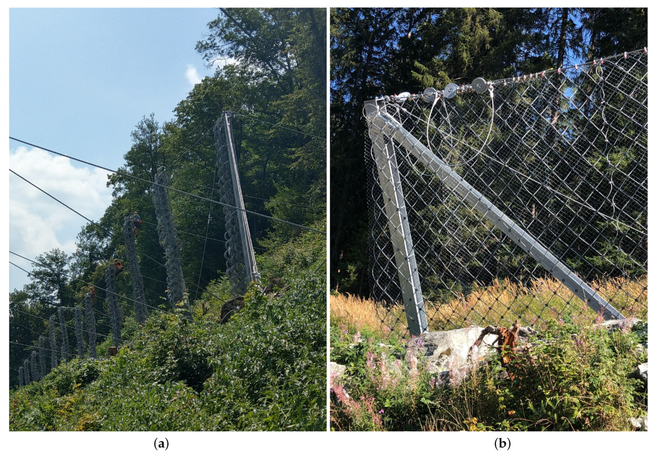
4]. The practical instructions for the planning engineer contain a checklist of the minimum requirements that need to be fulfilled. In practice, the supplier submits the entire test and product documentation to an independent inspection body for an evaluation of the barrier’s performance characteristics. Based on the defined requirements, like the priority performance the adaptability, the assembly (see
Figure 1a), and maintenance criteria, as well as the official documentation, are all assessed and evaluated with a scoring system. If the recommended minimum requirements are met, the Federal website [
17] lists the barrier. This gives building contractors, planners, and users access to validated product information.
For the transformation of the rope forces, measured during the certification process, to a standard situation, procedural instructions and calculation examples are given by Baumann [
16]. The determined static equivalent loads are provided by the suppliers and can, thus, be compared with those of other manufacturers. They also form the basis for the design of anchorages and foundations. The Federal Office [
16] provides the planner with binding calculation specifications for the handling of special structures. For example, the handling of additional posts instead of lateral ropes (
Figure 1b) are specified.
The roles and duties within a mitigation project were defined as follows: the planner checks the project-related usability of the barrier. The designing engineer must carry out the dimensioning of foundations and anchors on the basis of the relevant forces. He is also responsible for determining test and inspection anchors and for supervising the execution of construction work. For site-specific adjustments of the barrier, the engineer must request additional information and proof from the supplier if required. The contractor is responsible for carrying out and recording the drilling and anchor injection work, carrying out tests on test anchors, and for a professional installation of the barrier. The user, or his representative, is responsible for defining the objectives of the measures and formulating suitability, as well as requirements, for the corrosion protection level of the anchorage, along with carrying out maintenance and repair work.
The supplementary quality assessment and the additional practical recommendations have significantly improved the project suitability of the barriers used in Switzerland compared to countries in which no verified manufacturer information is available. Numerous successfully implemented practical examples confirm this.
6. Adaption of Standard Barriers
Flexible protection systems are—as their name suggests—well suited to be adapted to different boundary conditions in the field, i.e., to cross gullies or to be directly be erected without lateral anchorage (
Figure 1b). However, it must be clear that a modification of the barrier’s structure affects its performance. But, how much variation is acceptable? Baumann [
16] gives some standard suggestions regarding maximum length of a barrier and acceptable changes of longitudinal direction. Other adaptions have to be verified. Today’s available numerical methods to model rockfall protection barriers (see Reference [
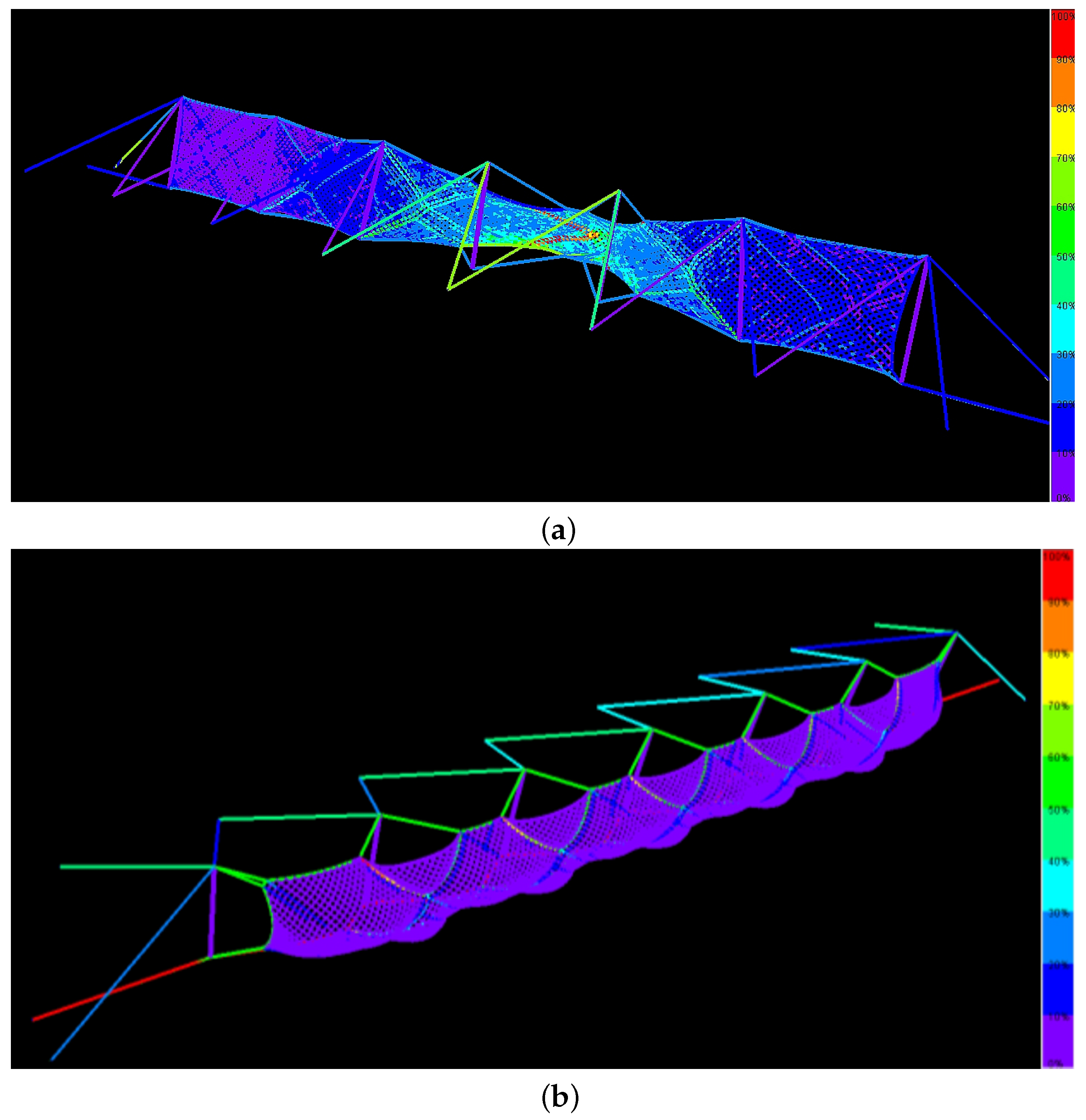
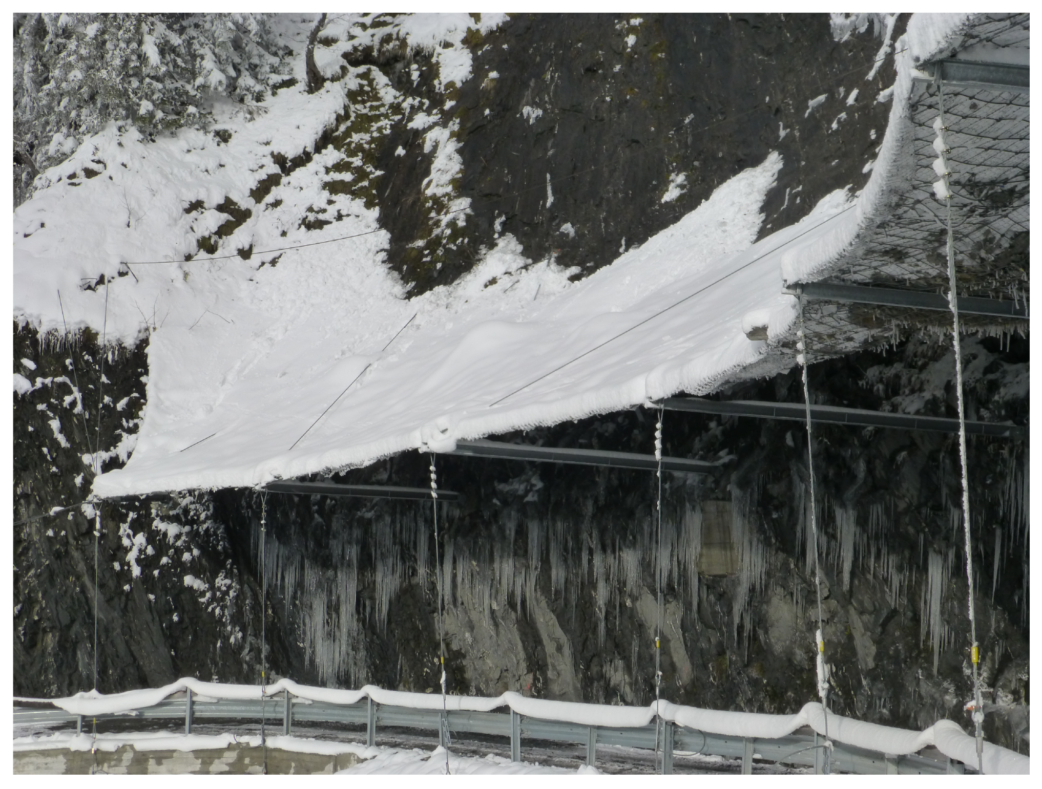
18] for an overview) easily enable such structural adaptions. However, any simulation first should first be verified by existing test data of a standard system. After that, the influence of a structural modification can be documented. An example can be seen in
Figure 2 and
Figure 3, where a certified 2000 kJ rockfall barrier has been strengthened to also withstand shallow landslides, without affecting the dynamic behaviour under a rockfall impact. Do keep in mind that, when evaluating simulations, it can be rather simple to produce nice looking pictures and animations of barriers. The challenge for each simulation is, however, to predict the ultimate capacity of a barrier.
7. Final Remarks
In principle, users for flexible rockfall protection systems are in a good position because the market provides a wide variety of reliable systems [
4]. Therefore, they simply have to decide which boundary conditions are valid for each specific site. This, for example, involves the consideration of possible obstacles on the slope that might interfere with a smooth dynamic performance. Another key aspect is the expected rockfall energy. Maybe it is better not to choose a barrier with a match of its maximum energy capacity and the expected rockfall energy. Instead, a barrier should have a service energy level at which it does not need too much maintenance due to rockfall events that are typical for the specific site. In addition, the user should keep in mind whether the expected loadings are within the tested range. What happens, for example, to small and fast rockfall events [
5]? Can we expect different load cases as, e.g., shown in
Figure 2 and
Figure 3?
Another interesting topic is the durability of a barrier, especially in regard to corrosion. Fifty or more years can easily be promised. The question is whether the manufacturer will then still be in business to take responsibility in case of corrosion?
In the end, if the user has a critical look at his specific barriers and does not only accept every offer as the perfect solution for all varieties in nature, he can be sure that a reliable barrier will secure his surroundings for many years. And last but not least, one would hope that market competition not only favours the least expensive systems but also considers quality issues.


