
Examining the Effects of Suction and Nonlinear Strength Envelopes on the Stability of a High Plasticity Clay Slope

Department of Civil and Environmental Engineering, Auburn University, Auburn, AL 36849, USA
*
Author to whom correspondence should be addressed.
Geosciences 2021, 11(11), 449; https://doi.org/10.3390/geosciences11110449
Submission received: 15 September 2021
/
Revised: 29 October 2021
/
Accepted: 29 October 2021
/
Published: 31 October 2021
(This article belongs to the Special Issue Slope Stability Analyses and Remedial Measure of Failed Slopes)
Abstract
:Slope failures in high plasticity clay deposits are common occurrences in many parts of the world. In western and central Alabama, expansive Prairie clays are commonly found, and shallow slope failures have occurred in both fill and cut slopes containing these high plasticity clays. The objective of this study was to examine the effects of suction and the use of nonlinear strength envelopes on the embankment stability of a section of highway AL-5. The testing program consisted of fifteen ring shear tests performed using a Bromhead Ring Shear Device. The results of the tests were used to develop both linear and nonlinear fully softened and residual strength envelopes. The saturated strength envelopes are then used in a limit equilibrium slope stability analysis with and without the effects of suction. The results show stability (factor of safety >1) for all cases except the residual friction angle without suction. Given these results, large slope failures are unlikely to occur in this area, but surficial failures and deformations due to creep may be possible. These results demonstrate the importance of considering the effects of suction and nonlinear strength envelopes when examining the potential for shallow slope failures in high plasticity clays.
1. Introduction
Shallow slope failures are a common occurrence in both fill and cut slopes in western Alabama. In this area and others, expansive clays in the Selma, Tuscaloosa, and Midway Groups (Figure 1), sometimes referred to as Prairie clays, exhibit very low strengths causing repeated failures of even relatively flat slopes. Failures in geologic units with Prairie clays cost the state of Alabama a significant amount of money each year. The Alabama landslide database [1] found that almost USD 16 million was spent to repair slope failures in the Selma, Tuscaloosa and Midway Groups between 2005 and 2015. This figure only includes landslides for which federal emergency relief funds were requested, so the repair cost for all landslides in these units is likely much higher. This figure also does not include maintenance costs to repave and regrade shoulders failures [2]. It is believed that these failures can be partially explained through strength loss due to repeated cycles of wetting and drying in the high plasticity clays that are ubiquitous in these regions. This reduction in strength can lead to failure without any change in loading [3]. Understanding the strength of these soils is critical to be able to design effective repairs and avoid repeated failures.
Soil strengths for slope stability studies are commonly estimated using triaxial tests on undisturbed or remolded samples, but while these tests can be used to measure the fully softened strength (i.e., the peak drained shear strength of a clay soil under normally consolidated conditions as defined by [5]), they cannot reach large enough shear strains to accurately determine the residual strength. In overconsolidated clays, softening tends to occur quickly after reaching the peak strength [6], therefore, residual strengths can be an important factor in measuring the stability of overconsolidated clay slopes [3,4,5,6,7,8,9,10,11]. The ring shear test [12,13,14] can be used to measure residual strengths of clays, but its use in practice is still limited due to limited availability of the equipment in commercial laboratories and the difficulty in preparing high quality specimens. To overcome some of the difficulties in both the laboratory and field measurements of fully softened strengths, correlations have been developed which relate the long-term strength of the clay to an index property such as the Atterberg limits (e.g., [15,16,17,18,19,20]), which is commonly measured during routine geotechnical investigations. These correlations depend on the properties and mineralogy of the clay deposit, so correlations must be developed or verified for use in regions where these materials are found. Previous authors have also highlighted the importance of considering nonlinear strength envelopes for both fully softened and residual strengths [15,17,21], although the use of these envelopes is still limited in practice.
The research site for this study is located west of Selma, AL in Perry County (Figure 1). The highway in this area is generally flat with the surrounding land consisting of wooded areas and farms. Other areas of this highway (AL-5) with the similar soils have experienced slope failures in the past, such as a failure that led to the placement of rockfill berm on an embankment approximately five miles south of the project site (Figure 2a). Stallings [2] observed cracking along the shoulders of the roadway within the study area that was not clearly attributed to swelling and some rutting and bulging was observed along the embankment face (Figure 2b). The combination of cracking and bulging led to the hypothesis that slope movements might be occurring within the study area. Jackson [8] measured moisture contents and suction values beneath the roadway and found that suction has been present during the duration of the study period (November 2016–December 2019) and much of the embankment and foundation was saturated, but negative pore pressures were observed in the embankment. The objective of this study is to examine the effects of suction and the use of nonlinear strength envelopes on the stability of the embankments in this region of AL-5 to determine if slopes failures are likely to occur. While the study is focused on AL-5, landslides in high plasticity, expansive clays are common in multiple areas (e.g., [3,22,23,24]) and understanding the strengths of these materials is key to designing repairs.
2. Background
2.1. Landslides in High-Plasticity Clays
Selecting strengths for use in slope stability analyses is often a key source of uncertainty and selected strengths must account for effects of loading conditions and any potential changes in strength over time. For slopes along highways, long-term drained strengths are often used to analyze failures that occur without significant changes in loading [22], such as those observed along AL-5. This is especially true for expansive clays, such as the Prairie clays considered in this study, where the strengths can be reduced as repeated cycles of wetting and drying occur potentially leading to failures in areas of sloping ground [23]. Groundwater fluctuations have also been shown to be an important factor in landslide development along highways where the roadway is underlain by expansive clays [3,24]. Accounting for this potential strength loss when analyzing the stability of these slopes will therefore be important to obtain accurate results.
In this study, the term fully softened shear strength is defined as the peak strength of drained strength of a normally consolidated clay, which has been found to be equivalent to the long-term drained strength of stiff fissured clay soils [5]. This definition is also used by US Army Corps of Engineers [25]. The fully softened strength is distinct from the critical state strength [22,26], which represents the shear strength of the soil when no further dilation or contraction occurs [27]. The critical state strength is usually lower than and occurs at a larger displacement than the fully softened strength [22], but at smaller displacements than the residual strength [22,28,29].
Several authors have examined landslide case histories to determine the appropriate strength to use in analyzing failures in clay slopes. Stark and Eid [15] found that the fully softened shear strength was appropriate to use when analyzing first-time failures in natural cut slopes and compacted embankments. Mesri and Shahien [17] reanalyzed a large database of slope failures in soft clays, stiff clays and clay shales to assess the mobilized shear strength. They found that first-time failures were primarily controlled by the fully softened strength, while residual strengths controlled reactivated landslides. Reactivated landslides are landslides that resume movement after a period of inactivity and the shearing resistance is commonly reduced to the residual condition along the entire failure surface [17]. Both of these studies highlighted the importance of considering the stress-dependent nature of the strength envelopes through either nonlinear envelope or use of secant friction angles. A study of long-term slope stability of slopes in shale regions in the Sydney Basin found that both landslide occurrence and long-term slope stability were governed by the residual shear strengths [30]. Residual strengths have also been recommended for being used for the long-term slope stability of clay soils by Skempton [5,10,11,31], Tiedemann [32] and Haefeli [33]. Correlations for both fully softened and residual shear strengths with index properties, such as the liquid limit and plasticity index, have been developed by multiple authors (e.g., [15,16,17,18,19,20]).
2.2. Shear Strength Envelopes
The previous studies have highlighted the importance of measuring the drained strengths of clays to assess the long-term stability of the slopes. Drained (or effective stress) strength envelopes are commonly used to evaluate slope failures that occur due to long-term loading as opposed to loads that are applied rapidly relative to the permeability of the soil [22]. Long-term drained shear strengths of saturated soils are commonly represented in slope stability analyses using an effective stress Mohr–Coulomb failure envelope as shown in Equation (1), where the effective cohesion is typically zero for uncemented soils.
where
= shear strength (kPa)
= effective cohesive intercept (kPa)
= = effective normal stress (kPa)
= total stress (kPa)
= pore water pressure (kPa)
= effective angle of internal friction (deg)
Nonlinear strength envelopes can be used when a linear fit does not match the data for a particular soil. Multiple authors have highlighted the importance of considering nonlinear strength envelopes for both fully softened and residual strengths [15,17,21] of fine-grained soils. This can be done through a stress-dependent secant friction angle or a strength envelope with a nonlinear functional form. An example of a nonlinear strength envelope is the power curve shown in Equation (2), which has been shown to work well for analyzing surficial shallow (normal stress lower than 45 kPa in this paper) slope failures [21].
where
a, b = dimensionless fitting parameters describing curvature and slope
= atmospheric pressure (kPa)
Correlations for the parameters a and b have been developed for fully softened strengths [20], but more work is needed to develop correlations for these values for residual strengths.
2.3. Effects of Suction on Strength
Soils above the groundwater table will have negative pore pressures (positive suction) that will increase the effective stress and therefore the strength of the soil. This increase in strength due to suction is important for many geotechnical problems, including landslides which may be triggered by reductions in suction during rain events [34]. The total suction in soils has two primary components. The first is the matric suction, which is defined as the difference between the pore water pressure (uw) and the pore air pressure (ua). The second component is the osmotic suction, which is associated with the salt content of the pore water. Osmotic suction is not considered in this study as it usually has a small effect on the shear strength of soils [35].
The effects of suction on the strength of the soil can be included through the use of an unsaturated strength envelope [36] as shown in Equation (3).
where
= unsaturated shear strength angle (kPa)
= pore air pressure (kPa)
= pore water pressure (kPa)
At suction values below the air entry value (AEV), and the unsaturated strength envelope reverts to the saturated strength envelope, but with a negative pore pressure. The AEV is defined as the matric suction value that is exceeded before air recedes into the soil pores [37]. When matric suction exceeds the air entry value, the strength envelope for the soil can be described by Equation (3). This envelope is often assumed to be bi-linear (Figure 3), but has also been shown to be dependent on the suction value resulting in a nonlinear envelope at higher suction values [38]. can be measured using suction-controlled tests or can be determined using empirical models, such as those developed by Khalili and Khabbaz [39] and Vanapalli et al [40]. Figure 3 illustrates the correlation of saturated and unsaturated condition with the air entry value (AEV).
3. Materials and Methods
The objective of this study is to examine the effects of suction and the use of nonlinear strength envelopes on the stability of a high-plasticity clay embankment along AL-5. To accomplish this objective, fully softened and residual shear strengths of remolded specimens collected from the site were measured using drained ring shear tests on saturated specimens. The testing program consists of fifteen ring shear tests performed using a Bromhead Ring Shear Device [12]. This section describes the study location, the soil samples collected, and the ring shear testing methodology used in this study.
3.1. Study Location
The four-mile section of Alabama Highway 5 considered in this study is located between mile marker 50.85 to mile marker 54.85. Most of this area is classified as Mooreville Chalk, which is part of the Selma Group, on geologic maps [4], but surficial soils are primarily high plasticity clays with the intact chalk layers being found at greater depths. This section of roadway is constructed on a 1.5 m tall embankment made primarily of excavated, weathered chalk. Stallings [2] performed an extensive characterization of the soils at this site and found that the embankment and foundation soils were similar and contained a substantial amount of expansive clay (samples in this paper had a 54% clay fraction), as determined using one-dimensional swelling tests. This was determined to be the likely cause of pavement distress observed at the site [2,7,8].
Kennedy [7] performed preliminary slope stability analyses of a typical section in this area using preliminary ring shear test results on samples collected from the research site. Kennedy [7] determined that factors of safety (FS) for these embankments were close to 1.0 when using fully softened strengths (used for first-time failures) and near 0.5 when considering residual strengths. While these analyses indicated that slope failures were likely to occur within this section of the highway, the previous analyses only considered linear strength envelopes and did not consider the effects of suction within the embankment.
3.2. Soil Samples and Properties
Soil samples were collected at the area of potential instability using thin-walled tube samplers. Samples tested in this study were from depths between 1.0 and 5.5 m in boreholes B5.5 and B6.5 located at mileposts 53.1 and 53.6, respectively (Figure 1). Index testing on these soils was performed by Stallings [2] and results are summarized in Table 1. The soils classified as Fat Clay (CH) according to the Unified Soil Classification System or A-7-6 according to the AASHTO classification system with an average fines content of 78% [2]. Stallings [2] also performed swell tests on these soils and found the clays were expansive and capable of generating swell pressures between 24 and 67 kPa for samples collected from B5.5 and B6.5.
In order to estimate the AEV, a soil water characteristic curve was developed based on the data collected by Jackson [8] using moisture sensors (Decagon Devices GS1) and suction sensors (Decagon MPS6) installed within the boreholes in the embankment (Figure 4). The AEV was estimated by extending the lower straight-line portion of the SWCC to find the intersection with a saturation of 100% based on the recommendations of Fredlund et al. [38]. Using this procedure, the AEV for these soils is approximately 800 kPa. This is greater than the maximum suction values considered in this study (approximately 22 kPa from the limit equilibrium analyses presented later), so only the saturated portion of the strength envelope (defined by for a linear envelope with ) is needed in the current study.
3.3. Torsional Ring Shear Testing
Stark and Eid [15] found that the torsional ring shear test was an accurate and timesaving method to obtain both fully softened and residual strengths compared with triaxial tests. The testing method have also been used to characterize fully softened and residual strength parameters of the landslides consisting of expansive clay minerals [41]. This test is performed by placing a remolded soil specimen in a steel ring between two porous stones (Figure 5a). The upper stone is then rotated relative to the bottom stone to shear the specimen. The specimen and porous stone interface are important as the porous stone should not slide across the surface of the soil [42]. For the current study, brass porous elements were machined to have a rough surface (Figure 5b), as recommended by Stark [42], to ensure that the torsional loading was properly transferred to the soil specimen. Details on the machining of the porous stones are discussed by Kennedy [7]. Normal stress is applied using a counter balanced lever loading system. The shear loading is applied at a slow rate to assure drainage of any excess pore pressures. The tests for this study were performed in general accordance with the procedures discussed in ASTM D6467 [13] using the “flush” procedure, which ensures the top porous stone remains approximately flush with the surface of the specimen container. All tests were performed on saturated specimens. Details on the testing procedure used for this study are discussed in the next section. Only one test is performed for each specimen as recommended by previous researchers [14].
To prepare the soils for ring shear testing, the samples were first oven dried and sieved through a No. 40 sieve to remove any large particles to ensure the uniformity. Very few particles were larger than the No. 40 sieve, so this sieving is expected to have a minimal effect on the strength. Distilled water was added to the material until a target average gravimetric water content (44%) was achieved which corresponded to a saturated condition and a liquidity index (LI) of approximately 0.6 to minimize trapped air during placement of soil into the container. A higher gravimetric water content could not be achieved as the soils were too soft to then prepare a specimen for testing. Once the soil was prepared with the correct water content, the material rehydrated for at least 24 h in a humidity-controlled environment. The masses of the empty specimen container, porous stones, and top platen were recorded prior to each test. After rehydrating for 24 h, the soil was placed into the specimen container using a spatula and a razor blade was used to cut the soil flush with the top of the specimen container. The specimen and container were weighed to determine the amount of soil in the container. The specimen and container were then placed in the ring shear device and the water bath was filled to submerge the specimen in order to prevent specimen from drying and to maintain saturation during testing. Preconsolidation loads of either 0.1, 0.7, and 1.0 kg were placed on the loading arm (corresponding to a normal stress of 5, 19, and 25 kPa on the specimen in Bromhead ring shear apparatus) and the vertical displacement was monitored. The magnitude of the preconsolidation load was based on the available weights with the requirement that it be less than the consolidation load used for the shearing phase. The load was left in place for ten minutes or until vertical movements had stopped.
Tests were performed at eight stress levels (21, 36, 44, 61, 76, 99, 125, and 149 kPa) in order to characterize the strength envelopes across a wide range of stress levels, including the expected in-situ stresses in the embankment and foundation. The specific stress values used in the testing program were based on the available loading weights. The specimen consolidated for 24 h under the applied load or until the consolidation process was complete as judged from the settlement rate. According to ASTM D6467 [13], specimens must not settle more than 15% of the initial specimen height during consolidation. For the device used in this work, this would correspond to a maximum settlement of 1.2 mm. The maximum settlement for this study was set as 0.75 mm and tests with settlements larger than this were not used. When consolidation was complete, shear was applied using a rotational rate of 0.03 degree/min, as recommended for high plasticity clays [13]. The shear displacement required to reach the residual shear strength is about 20 mm for the specimens in this study. Previous studies have found similar levels of displacement are needed to reach a residual condition for remolded samples [16,22]. Data was recorded for 24 h or until a well-defined residual strength state was obtained. After shearing, the top platen was carefully separated from the specimen to check that a well-defined failure plane had formed. Tests without a well-defined failure plane within the soil would have been discarded, but all tests in the current study showed a well-defined failure plane. Both the fully softened and residual shear stresses were recorded from each test.
4. Torsional Shear Testing Results
The response of three of the tested specimens is shown in Figure 6. The remolded samples quickly reach a peak followed by a large drop in strength. This peak is defined as the fully softened strength of the soil. After a certain amount of shear displacement (approximately 20 mm for these tests), the shear stress is approximately constant, and the sample is assumed to have reached a residual strength. This process is repeated for multiple stress levels to define a strength envelope (Figure 7). All specimens were saturated.
The fully softened and residual strength envelopes from the fifteen specimens tested in this study are shown in Figure 7 for the eight normal stress levels considered. While there is some scatter in the data, fifteen tests are believed to be sufficient to define the average strength envelopes over this range of stresses. Both linear and power fit strength envelopes were considered, and the corresponding equations are shown in Table 2. The test data clearly indicates that the strength envelopes are nonlinear with lower secant friction angles at higher stresses as expected. The power envelopes are fit using data up to the higher bound of 149 kPa, while the linear envelopes for the slope stability analyses are fit to the data at stresses less than or equal to 44 kPa in order to be representative of the expected stress levels within the embankment. It should be noted that the residual friction angle used in this study (13.7 degrees) is higher than the one used by Kennedy [7] (11.5 degrees) because only the test data at lower stresses was used to fit the envelope in this study. The power and linear envelopes are similar for both fully softened and residual strengths at larger stresses, but the power envelopes give higher strengths at lower stresses (Figure 7). Both types of envelopes will be considered in the slope stability analysis.
Comparison with Previous Studies
The strength envelopes (Table 2) developed in this study were compared with the correlations developed by Mesri and Shahien [17], Stark and Hussain [18], and Stark and Fernandez [20] for the fully softened and residual strengths of clays (Figure 8). The correlation from Stark and Hussain [18] was plotted for Liquid Limit (LL) values of 71 and 86 and Mesri and Shahien [17] and Stark and Fernandez [20] were plotted for Plasticity Index (PI) values of 47 and 60 to capture the range observed in this study. The lower bound relationship from Mesri and Shahien [17] was used as it provided a better fit to the current data. All envelopes show reasonable agreement with the correlations and the envelopes from this study would fall well within the scatter of the data used to develop the correlations. The fully softened strength agrees better with Stark and Hussain [18], while the residual strength agrees better with the lower bound relationship from Mesri and Shahien [17]. The residual friction angle also falls within the range of data by Lupini et al. [29] for soils with similar PIs. This consistency with previous studies gives additional confidence in the current results.
5. Slope Stability Analyses
Slope stability analyses were performed to determine the likelihood of slope failure along this section of AL-5. Analyses were performed using the limit equilibrium slope stability software Slide published by Rocscience [43]. The cross-section near Boring 5.5 was used for the analyses (Figure 9) and the soil profiles were obtained from boring logs [2,9]. The embankment in this area is approximately 1.5 m tall and the pavement is relatively thick (0.3 m) due to many years of repaving to repair damage from swelling clays. The water table was placed 0.69 m lower than the embankment for these analyses based on in-situ measurements and field observations. The strength envelopes developed from the ring shear data (Table 2) were used to represent the clay embankment and foundation. Strength data for foundation material was the same as embankment, but with a slightly higher density. The intact chalk layer (located approximately 2 m below the embankment) was not included in the stability analyses, but no failure surfaces extended to more than 1.0 m into the foundation. Selected properties for all of the layers are shown in Table 3. The properties for the pavement were based on the lower bound of the triaxial test results presented by Christensen et al. [44] and the densities of the embankment and the foundation were based on tests performed by Stallings [2].
5.1. Effect of Strength Envelope
The results of the slope stability analyses without suction are shown in Table 4. The critical surface for both linear envelopes without suction is very shallow and approximates an infinite slope failure condition. This is not surprising as an infinite slope failure is often the critical case for dry frictional materials. The slope angle of the embankment is approximately 20 degrees and so the fully softened friction angle gives adequate stability, while the residual strength friction angle shows instability would be expected for an infinite slope failure. The analyses for the residual envelope were re-run with a minimum slice depth of 0.5 m to examine the stability against larger failures (Figure 10). These results still show a factor of safety below 1.0 indicating that larger failures may be expected if these residual strengths are mobilized, and the effects of suction are removed. The fully softened results, which would be used for first-time slides, indicate that adequate stability would be expected even without suction, so a failure would need to be initiated by some external loading or a significant change in the water table in order to mobilize the residual strengths.
Using the power envelope increases the factors of safety for both strength cases compared with the linear fits. The critical failure surface using the power envelope is similar to the linear case with the minimum depth constraint (Figure 11). This difference in factor of safety is due to the higher strengths at very low stresses using the power fit compared with the linear fit. The two envelopes become equal at approximately 25 kPa (Figure 7) and below this stress level the power envelope gives higher strengths. The differences in the envelopes do not appear to be significant in Figure 7, but the effect on the minimum factor of safety is significant, even when considering a minimum depth constraint with the linear envelope. The differences in the strength values for the failure surface in Figure 10 are compared with the mobilized shear stress along each slice extracted from Slide in Figure 12. The effective normal stresses along the failure surface range from 0.17 to 9.0 kPa and in this range of stresses the differences between the two envelopes are significant compared with the mobilized shear stress. The ring shear procedure used in this study was unable to measure strengths below 20 kPa, but it is likely that a secant friction angle at very low stresses would be greater than the one calculated using data between 20 and 44 kPa. Further work is needed to compare the accuracy of the power fit with data at very low stresses, but it is important for future studies to recognize that even seemingly small differences in these envelopes can have a significant effect on the results for shallow failures.
5.2. Effect of Suction
The analyses in the previous section did not consider the effects of suction, but in-situ measurements within the embankment show that suction has been present during the duration of the study period (November 2016–December 2019). Figure 13 shows the lowest suction values measured during the study period at two depths for sensors located under the shoulder of the roadway. The minimum suction values were obtained because these would represent the critical case for slope instability. These results show that near the surface suction values were approximately 15 kPa along the shoulder and dropped to about 10 kPa near the base of the embankment. Lower suction values are expected at larger depths as these locations are closer to the water table and are less affected by evapotranspiration at the ground surface. These two measurements were insufficient to develop a complete profile of suction throughout the embankment as is needed for the slope stability analyses. Because of this, the suction values used in Slide were assumed to be equal to the height above the water table multiplied by the unit weight of water (Figure 13). This assumed profile closely matches the shallow shoulder sensor but underestimates the suction from the deeper sensor. Despite these differences, the assumed profile is considered reasonable for evaluating the possible effects of suction on the slope stability analyses. Obtaining a more realistic suction profile would require performing an unsaturated seepage analysis with infiltration and evapotranspiration (e.g., [9]), which is beyond the scope of the current study.
The results from the limit equilibrium analyses considering suction are shown in Table 4. Only the linear envelope (Equation (3) with ) was considered with suction, as suction values are not used with curved strength envelopes within Slide. Including the effects of suction results in a large increase in the factor of safety and pushes the critical failure surface into the foundation (Figure 14). The factors of safety for the linear envelope with suction are also larger than the results using power fit envelope. These high factors of safety are consistent with the lack of movement along these slopes during the duration of this study. This demonstrates the importance of considering reasonable suction profiles when analyzing slopes located above the water table. While designers of new slopes may neglect suction values to avoid relying on them for stability, when analyzing existing slopes, it is important to consider suction conditions as they are likely to exist in the field. For this section of embankment, the stability results do not suggest large failures are likely to occur even if suction is lost.
6. Discussion
Strengths of the Prairie clay soils within the study area of AL-5 were measured using ring shear testing. Both saturated fully softened and residual strengths of remolded clay samples were measured, and results compare well with results from previous studies for soils with similar Atterberg Limits. The fully softened strength was found to agrees better with Stark and Hussain [18], while the residual strength results were in good agreement with the lower bound relationship from Mesri and Shahien [17]. The results of this study further confirm the curved nature of these strength envelopes, which must be considered through either nonlinear strength envelopes or use of secant friction angles calculated at appropriate stress levels. While the ring shear testing can provide the strength of remolded samples, it cannot be used to measure the strength of intact samples. This approach has been shown to be reasonable for first-time failures in high plasticity clays, but likely underestimates the strength of the foundation material. Additional testing on the foundation would lead to higher strengths and therefore higher factors of safety, but this change would not affect the conclusions as the failure surfaces were primarily located within the embankment.
The slope stability analyses using a residual friction angle without suction suggest shallow failures are likely, while the other scenarios of residual strength envelopes and fully softened strength envelopes show adequate stability under current conditions. These factors of safety are higher than those found by Kennedy [7] for the same conditions, but these differences can be explained by (1) the change in the strength envelopes to focus on results at lower stresses and (2) the consideration of suction. Given the small size of the embankment and the curvature of the strength envelopes, it is important to consider strength envelopes that are applicable to the range of stresses that will be found along the failure surface. In this study, secant friction angles were considered for stresses between 20 and 44 kPa, which is likely reasonable for some of the deeper failure surface but is still too high for shallow failures. The power fit envelope eliminates the need for selecting applicable stress ranges as the true curvature of the envelope is explicitly included. No tests were performed at stresses below 20 kPa, so it is not known how well either envelope represents the strengths at very shallow depths. While many analytical approaches to analyze slope stability were based on linear envelopes, modern slope stability software can directly incorporate nonlinear envelopes like the power fit. Using the nonlinear envelope also eliminated the need to select an arbitrary minimum depth constraint. Using this power envelope, adequate stability (F.S. > 1.5) is found for first time failures even without consideration of suction and results for residual strengths are still well above 1.0.
Suction was also considered in the current study and found to significantly increase the factor of safety for the linear envelope, as expected. The inclusion of suction in the analyses increases the effective stress on each slice and so directly increases the strength along the slip surface. The effect is more pronounced at shallower depths where the increase in effective stress is more significant. In this study, the critical failure surface without suction approximated an infinite slope failure, while the critical failure surface with suction was much deeper and intersected the foundation. Suction was not considered with the power fit envelope as this is not available within the Slide software. If it had been considered, the factor of safety would have been even higher than shown in Table 4, providing further evidence that large failures are unlikely to occur at this location. In these analyses, the lowest suction values measured during the three-year monitoring period of this site were used to examine the most critical case from a stability standpoint. Suction is commonly ignored during design of new slopes to avoid relying on suction for stability. For existing slopes with deeper water tables, this approach is likely overly conservative and may lead to incorrect conclusions regarding stability.
All of the tests in this study were performed on saturated samples and no attempt was made to measure the unsaturated shear strength directly. Suction levels in the analyses used in this study were well below the AEV and so using the same friction angle for cases with and without suction is a reasonable approximation [38]. Future studies could consider performing suction-controlled strength tests to verify this assumption and directly measure the unsaturated strength of the soil. This is likely especially important for analyzing the strength of the soils near the slope face, which would be the most likely to become unsaturated due to higher rates of evapotranspiration near the surface. These soils are also the most likely to be subjected to repeated cycles of wetting and drying, which may reduce the strength and lead to failures (e.g., [45]). Examination of these effects, including consideration of infiltration, is left to future studies.
The original motivation for this study was observations of cracking along the shoulders and bulging along the slope faces of the embankments in the study area (e.g., Figure 2b). Previous studies had hypothesized that these observations were connected to slope instabilities, but this study has shown that adequate stability is expected for most realistic conditions. This study did not however consider localized loading by vehicles and mowing equipment that could lead to rutting or small failures. It is also possible that in periods of very heavy rain, the suction near the ground surface could be reduced enough to lead to surficial failures like those observed in the analyses using the linear residual strength envelope without suction. This study did also not consider the effects of creep or shrink/swell behavior that might lead to some spreading of the embankment. The results of this study demonstrate that no remediation or repairs are needed at this site to protect against large failures, but surface treatments could be used to reduce rutting and prevent surficial movements. Monitoring should continue to ensure that the observations remain consistent with these slope stability analyses.
7. Conclusions
The saturated residual and fully softened strengths (Table 2) of the expansive Prairie clays underlying a portion of AL-5 have been characterized using torsional ring shear testing. Samples were collected from an embankment where cracking has been observed along the shoulder and bulging has occurred on the slope face. Previous studies have hypothesized that slope instabilities may be leading to these observations. Tests were performed at normal effective stresses between 21 and 149 kPa to capture the range of stresses expected within the embankment and foundation. Over the stress range considered in this study, both linear and power envelopes provided a similar fit to the data, although the power envelopes gave higher strengths at low stresses. No tests were performed at stresses below 20 kPa, so it is not known how well either envelope represents the strengths at very shallow depths. The developed strength envelopes agree with previously developed correlations for soils with similar Atterberg Limits.
The strength results were used to perform limit equilibrium slope stability analyses of a representative cross-section where potential slope instability was suspected by previous studies. The effects of suction on the embankment stability were examined by performing analyses with and without consideration of negative pore pressures above the water table. The results show that under current conditions, both fully softened and residual strength envelopes would indicate stability (factors of safety larger than 1.0) except for the case of a linear residual strength envelope without suction. The linear residual strength envelope indicated that shallow failures would be expected to develop without the effects of suction, but the consideration of suction or the nonlinear envelope removes this concern. These results do suggest that heavy rain on a pre-existing failure plane might lead to instability. Future studies could examine the effects of rainfall on the stability of these slopes using transient seepage analyses that explicitly consider the effects of infiltration on the suction profile to better understand the likelihood of shallow failures. Future studies could also consider the influence of unsaturated strengths on the stability results.
The case history presented in this paper demonstrates the importance of considering both the effects of suction and curved failure envelopes when examining the stability of slopes with high plasticity clays. Previous studies have shown that both the fully softened and residual strength envelopes are curved for these types of soils, but differences between these envelopes are often considered to be relatively minor and consideration of nonlinear envelopes is uncommon in practice. This study demonstrates that seemingly small differences in strength envelopes can have a significant effect on the factor of safety for shallow failure surfaces. Similarly, suction is known to increase strength, but is commonly neglected in slope stability analyses. The results in this study demonstrate how neglecting suction and curvature of the strength envelope can lead to a conclusion that this slope is at risk for failure. This conclusion is at odds with observations at the site and could lead to unnecessary repairs being performed to address stability problems that are unlikely to occur. The consideration of suction or nonlinear strength envelopes indicates the slopes will remain stable even if residual strengths are mobilized and future studies should consider these effects when analyzing the potential for shallow slope failures in high plasticity clays.
Author Contributions
Conceptualization, J.M. and J.B.A.; Data Curation, M.X.; Formal Analysis, M.X.; Funding Acquisition, J.M. and J.B.A.; Methodology, J.M. and J.B.A.; Writing—Original Draft, M.X.; Writing—Review and Editing, J.M. and J.B.A. All authors have read and agreed to the published version of the manuscript.
Funding
Funding for this work was provided by the Alabama Department of Transportation.
Data Availability Statement
The data presented in this study are available upon request from the corresponding author.
Acknowledgments
The ALDOT Materials and Tests Bureau assisted with the collection of the landslide reports and soil samples. Elizabeth Stallings (Young) and Dan Jackson assisted with collecting the soil’s water content, suction values, and weather conditions. Lydia Kennedy assisted with the preliminary ring shear testing. Olaniyi Afolayan assisted with interpreting the suction data. The authors are very grateful for all of this assistance. This paper is based on a study supported by the Alabama Department of Transportation. This support is gratefully acknowledged. Any opinions, findings, or recommendations expressed herein are those of the authors and should not be interpreted as representing the official policies, either expressed or implied, of the above organizations or individuals.
Conflicts of Interest
The authors declare no conflict of interest.
References
- Knights, M.J.; Montgomery, J.; Carcamo, P.S. Development of A Slope Failure Database for Alabama Highways. Bull. Eng. Geol. Environ. 2020, 79, 423–438. [Google Scholar] [CrossRef]
- Stallings, E.G. Investigation of Pavement and Subgrade Distress at Alabama Highway 5. Master’s Thesis, Auburn University, Auburn, AL, USA, 2016. [Google Scholar]
- Khan, M.S.; Hossain, S.; Ahmed, A.; Faysal, M. Investigation of A Shallow Slope Failure on Expansive Clay in Texas. Eng. Geol. 2017, 219, 118–129. [Google Scholar] [CrossRef]
- Szabo, E.W.; Osborne, W.E.; Copeland, C.W., Jr.; Neathery, T.L. Geologic Map of Alabama, Geological Survey of Alabama Special Map 220, Scale 1:250,000. 1988. Available online: https://ngmdb.usgs.gov/Prodesc/proddesc_55859.htm (accessed on 30 October 2021).
- Skempton, A.W. First-Time Slides in Over-Consolidated Clays. Géotechnique 1970, 20, 320–324. [Google Scholar] [CrossRef]
- Holtz, R.D.; Kovacs, W.D.; Sheahan, T.C. An Introduction to Geotechnical Engineering, 2nd ed.; Pearson: Upper Saddle River, NJ, USA, 2011. [Google Scholar]
- Kennedy, L. Drained Residual Strength of Expansive Soils Causing Pavement Distress along Alabama Highway 5. Master’ s Thesis, Auburn University, Auburn, AL, USA, 2019. [Google Scholar]
- Jackson, D. Insitu Measurement of Pavement Distress and Causal Mechanisms in Expansive Soil along Alabama Highway 5. Master’ s Thesis, Auburn University, Auburn, AL, USA, 2016. [Google Scholar]
- Herman, J. Damage to Pavements from Expansive Clays: A Review of Behavior and Remediation Techniques. M.C.E. Research Paper, Auburn University, Auburn, AL, USA, 2015. [Google Scholar]
- Skempton, A.W. Slope Stability of Cuttings in Brown London Clay. In Selected Papers on Soil Mechanics; Thomas Telford Publishing: London, UK, 1984; pp. 241–250. [Google Scholar]
- Skempton, A.W. Residual Strength of Clays in Landslides, Folded Strata and the Laboratory. Géotechnique 1985, 35, 3–18. [Google Scholar] [CrossRef]
- Bromhead, E. A Simple Ring Shear Apparatus. Ground Eng. 1979, 12, 40–44. [Google Scholar]
- ASTM D6467, Standard Test Method for Torsional Ring Shear Test to Determine Drained Residual Shear Strength of Cohesive Soils. J. ASTM Int. 2013. [CrossRef]
- Stark, T.D.; Vettel, J.J. Bromhead Ring Shear Test Procedure. Geotech. Test. J. 1992, 15, 24–32. [Google Scholar] [CrossRef]
- Stark, T.D.; Eid, H.T. Slope Stability Analyses in Stiff Fissured Clays. J. Geotech. Geoenvirn. 1997, 123, 335–343. [Google Scholar] [CrossRef]
- Stark, T.D.; Eid, H.T. Drained Residual Strength of Sohesive Soils. J. Geotech. Geoenviron. 1994, 120, 856–871. [Google Scholar] [CrossRef]
- Mesri, G.; Shahien, M. Residual Shear Strength Mobilized in First-Time Slope Failures. J. Geotech. Geoenviron. 2003, 129, 12–31. [Google Scholar] [CrossRef]
- Stark, T.D.; Hussain, M. Empirical Correlations: Drained Shear Strength for Slope Stability Analyses. J. Geotech. Geoenviron. 2013, 139, 853–862. [Google Scholar] [CrossRef] [Green Version]
- Eid, H.T.; Rabie, K.H. Fully Softened Shear Strength for Soil Slope Stability Analyses. Int. J. Geomech. 2017, 17, 04016023. [Google Scholar] [CrossRef]
- Stark, T.D.; Fernandez, R. Fully Softened Shear Strength Measurement and Correlations. Geotech. Test. J. 2020, 43, 1201–1215. [Google Scholar] [CrossRef]
- Lade, P.V. The Mechanics of Surficial Failure in Soil Slopes. Eng. Geol. 2010, 114, 57–64. [Google Scholar] [CrossRef]
- Duncan, J.M.; Wright, S.G.; Brandon, T.L. Soil Strength and Slope Stability; John Wiley & Sons: Hokoben, NJ, USA, 2014. [Google Scholar]
- Hou, T.S.; Xu, G.L.; Shen, Y.J.; Wu, Z.Z.; Zhang, N.N.; Wang, R. Formation Mechanism and Stability Analysis of The Houba Expansive Soil Landslide. Eng. Geol. 2013, 161, 34–43. [Google Scholar] [CrossRef]
- Yilmaz, I.; Karacan, E. A Landslide in Clayey Soils: An Example from the Kızıldag Region of the Sivas-Erzincan Highway (Sivas-Turkey). Environ. Geosci. 2002, 9, 35–42. [Google Scholar] [CrossRef]
- Stephens, I.; Branch, A. Testing Procedure for Estimating Fully Softened Shear Strengths of Soils Using Reconstituted Material; Engineer Research and Development Center Vicksburg MS Geotechnical and Structures Lab: Vicksburg, MS, USA, 2013. [Google Scholar]
- VandenBerge, D.R.; Duncan, J.M.; Brandon, T.L. Fully Softened Strength of Natural and Compacted Clays for Slope Stability. In Proceedings of the Geo-Congress 2013: Stability and Performance of Slopes and Embankments III, San Diego, CA, USA, 3–7 March 2013; pp. 221–233. [Google Scholar]
- Schofield, A.N.; Wroth, P. Critical State Soil Mechanics; McGraw-Hill London: London, UK, 1968; Volume 310. [Google Scholar]
- Crabb, G.; Atkinson, J. Determination of Soil Strength Parameters for The Analysis of Highway Slope Failures. In Proceedings of the Slope Stability Engineering Developments and Applications, Proceedings of the International Conference on Slope Stability Organized by the Institution of Civil Engineers, Isle of Wight, UK, 15–18 April 1991; pp. 13–18. [Google Scholar]
- Lupini, J.; Skinner, A.; Vaughan, P. The Drained Residual Strength of Cohesive Soils. Geotechnique 1981, 31, 181–213. [Google Scholar] [CrossRef]
- Dunkerley, D. A Study of Long-Term Slope Stability in the Sydney Basin, Australia. Eng. Geol. 1976, 10, 1–12. [Google Scholar] [CrossRef]
- Skempton, A.W. Long-Term Stability of Clay Slopes. Géotechnique 1964, 14, 77–102. [Google Scholar] [CrossRef] [Green Version]
- Tiedemann, B. Über die Schubfestigkeit Bindiger Böden; Preuß. Versuchsanst. f. Wasserbau u. Schiffbau: Berlin, Germany, 1937; Available online: https://link.springer.com/chapter/10.1007/978-3-7091-7999-4_1 (accessed on 30 October 2021).
- Haefeli, R. Investigation and Measurements of the Shear Strengths of Saturated Cohesive Soils. Geotechnique 1951, 2, 186–208. [Google Scholar] [CrossRef]
- Taha, M.R.; Hossain, M.K.; Mofiz, S.A. Effect of Suction on the Strength of Unsaturated Soil. In Proceedings of the Advances in Unsaturated Geotechnics, Denver, CO, USA, 5–8 August 2000; pp. 210–221. [Google Scholar]
- Leong, E.-C.; Abuel-Naga, H. Contribution of Osmotic Suction to Shear Strength of Unsaturated High Plasticity Silty Soil. Geomech. Energy Environ. 2018, 15, 65–73. [Google Scholar] [CrossRef]
- Fredlund, D.G.; Morgenstern, N.R.; Widger, R.A. The Shear Strength of Unsaturated Soils. Can. Geotech. J. 1978, 15, 313–321. [Google Scholar] [CrossRef]
- Fredlund, D.G.; Rahardjo, H. Soil Mechanics For Unsaturated Soils; John Wiley & Sons: Hoboken, NJ, USA, 1993. [Google Scholar]
- Fredlund, D.G. Unsaturated Soil Mechanics in Engineering Practice. J. Geotech. Geoenviron. 2006, 132, 286–321. [Google Scholar] [CrossRef] [Green Version]
- Khalili, N.; Khabbaz, M. A Unique Relationship for χ for the Determination of the Shear Strength of Unsaturated Soils. Geotechnique 1998, 48, 681–687. [Google Scholar] [CrossRef]
- Vanapalli, S.K.; Fredlund, D.G.; Pufahl, D.E. The Relationship Between the Soil-water Characteristic Curve and the Unsaturated Shear Strength of A Compacted Glacial Till. Geotech. Test. J. 1996, 19, 259–268. [Google Scholar] [CrossRef]
- Bhandary, N.P.; Yatabe, R. Ring Shear Tests on Clays of Fracture Zone Landslides and Clay Mineralogical Aspects. In Progress in Landslide Science; Springer: Berlin/Heidelberg, Germany, 2007; pp. 183–192. [Google Scholar]
- Stark, T.D. Discussion of “Correlations for Fully Softened Shear Strength Parameters”. Geotech. Test. J. 2017, 40. [Google Scholar] [CrossRef]
- Rocscience SLIDE Version 9.0. Available online: http://www.rocscience.com (accessed on 30 October 2021).
- Christensen, D.; Bonaquist, R.; Jack, D. Evaluation of Triaxial Strength as A Simple Test for Asphalt Concrete Rut Resistance; 2000; Available online: https://trid.trb.org/view/666395 (accessed on 30 October 2021).
- Khan, S.; Ivoke, J.; Nobahar, M. Coupled Effect of Wet-Dry Cycles and Rainfall on Highway Slope Made of Yazoo Clay. Geosciences 2019, 9, 341. [Google Scholar] [CrossRef] [Green Version]
Figure 1.
Locations of geologic units containing the high plasticity Prairie clays (after [4]) and the location of the research site and borings examined in the current study.
Figure 1.
Locations of geologic units containing the high plasticity Prairie clays (after [4]) and the location of the research site and borings examined in the current study.
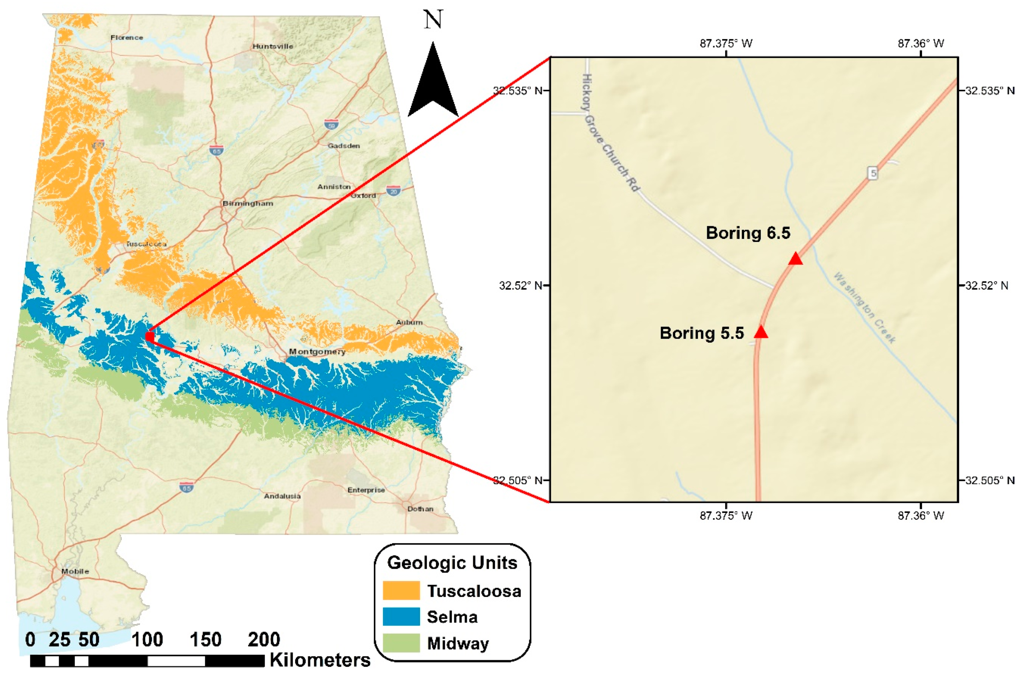
Figure 2.
Photos of: (a) a repaired slope failure in an embankment section of AL-5 in Perry County approximately five miles south of the project site; (b) a shallow slope movement leading to cracking in the travel lane and bulging at the toe of the embankment (as highlighted by the mower tracks).
Figure 2.
Photos of: (a) a repaired slope failure in an embankment section of AL-5 in Perry County approximately five miles south of the project site; (b) a shallow slope movement leading to cracking in the travel lane and bulging at the toe of the embankment (as highlighted by the mower tracks).
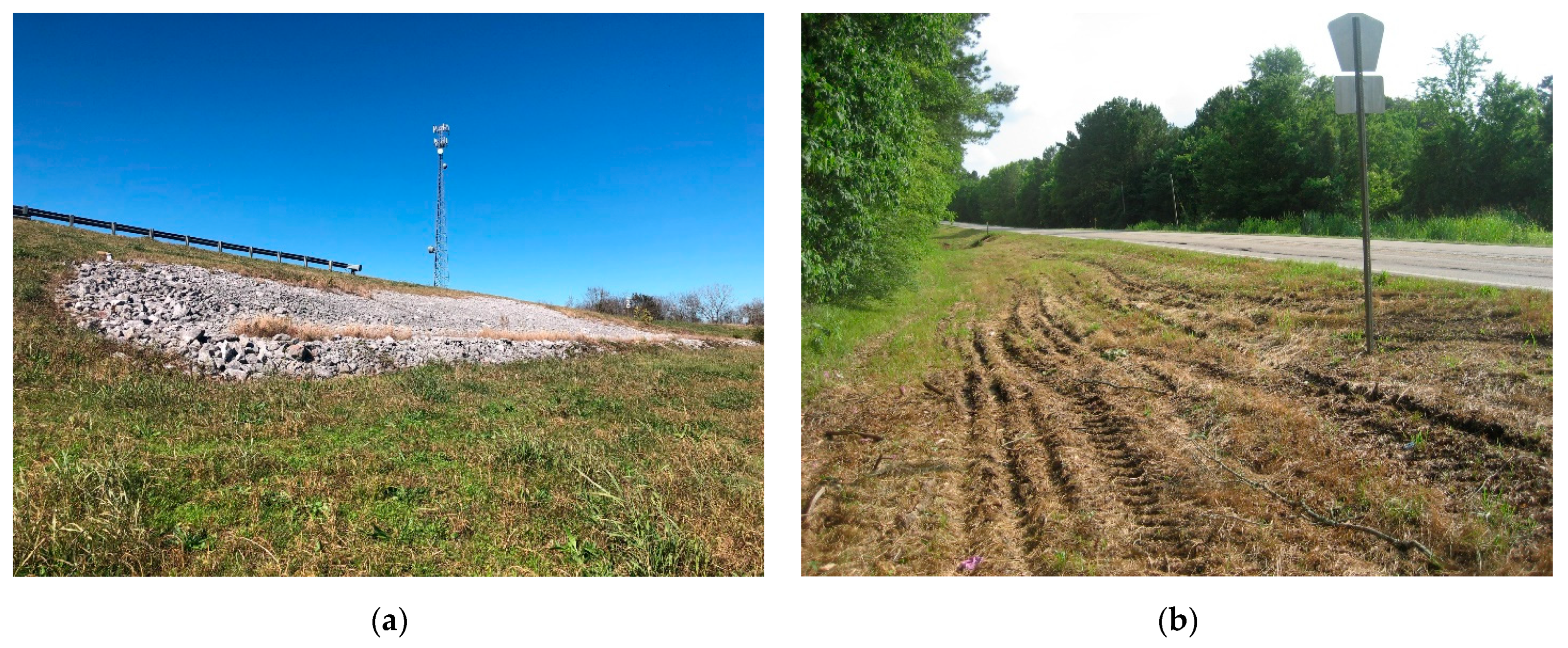
Figure 3.
Effect of air entry value on unsaturated shear strength envelopes [38].
Figure 3.
Effect of air entry value on unsaturated shear strength envelopes [38].
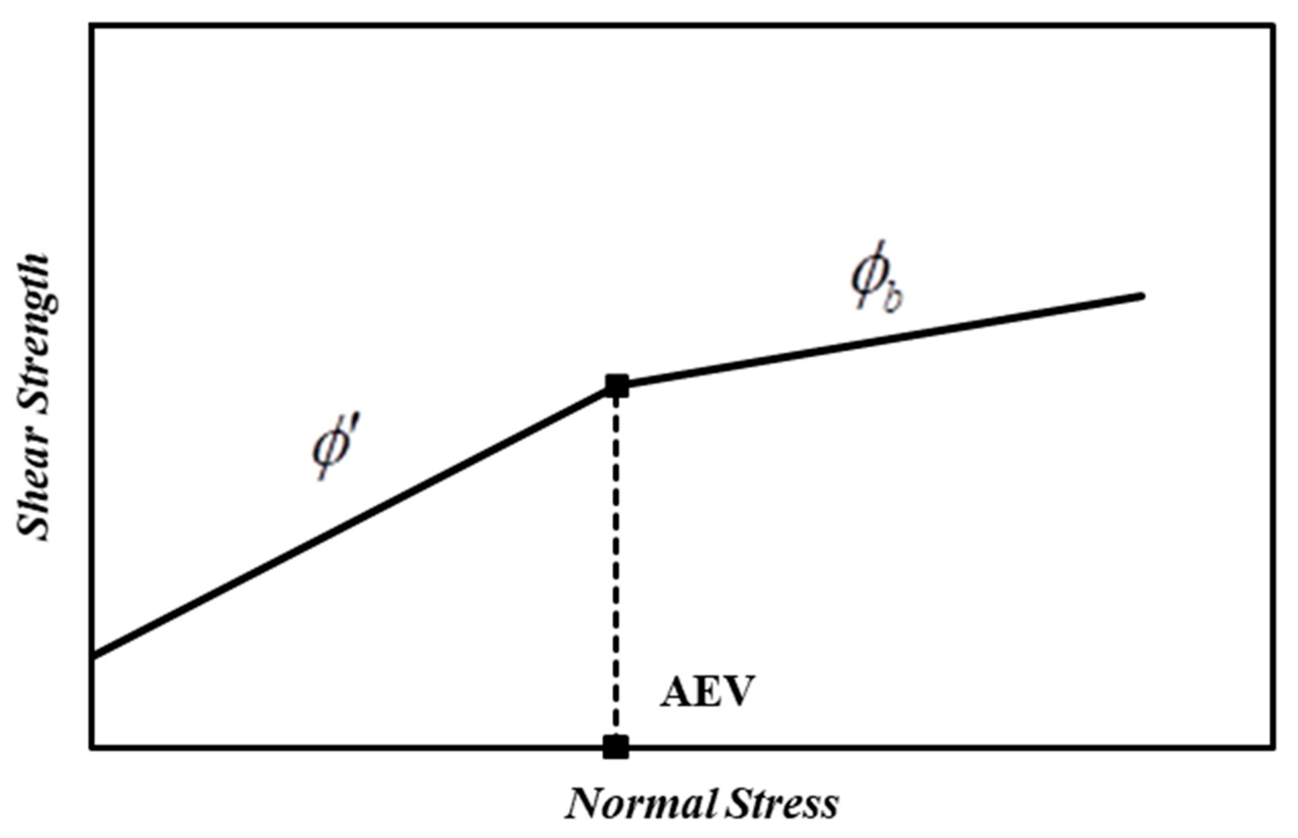
Figure 4.
Soil water characteristic curve from the clay at AL-5 based on in-situ measurements of moisture content and suction.
Figure 4.
Soil water characteristic curve from the clay at AL-5 based on in-situ measurements of moisture content and suction.
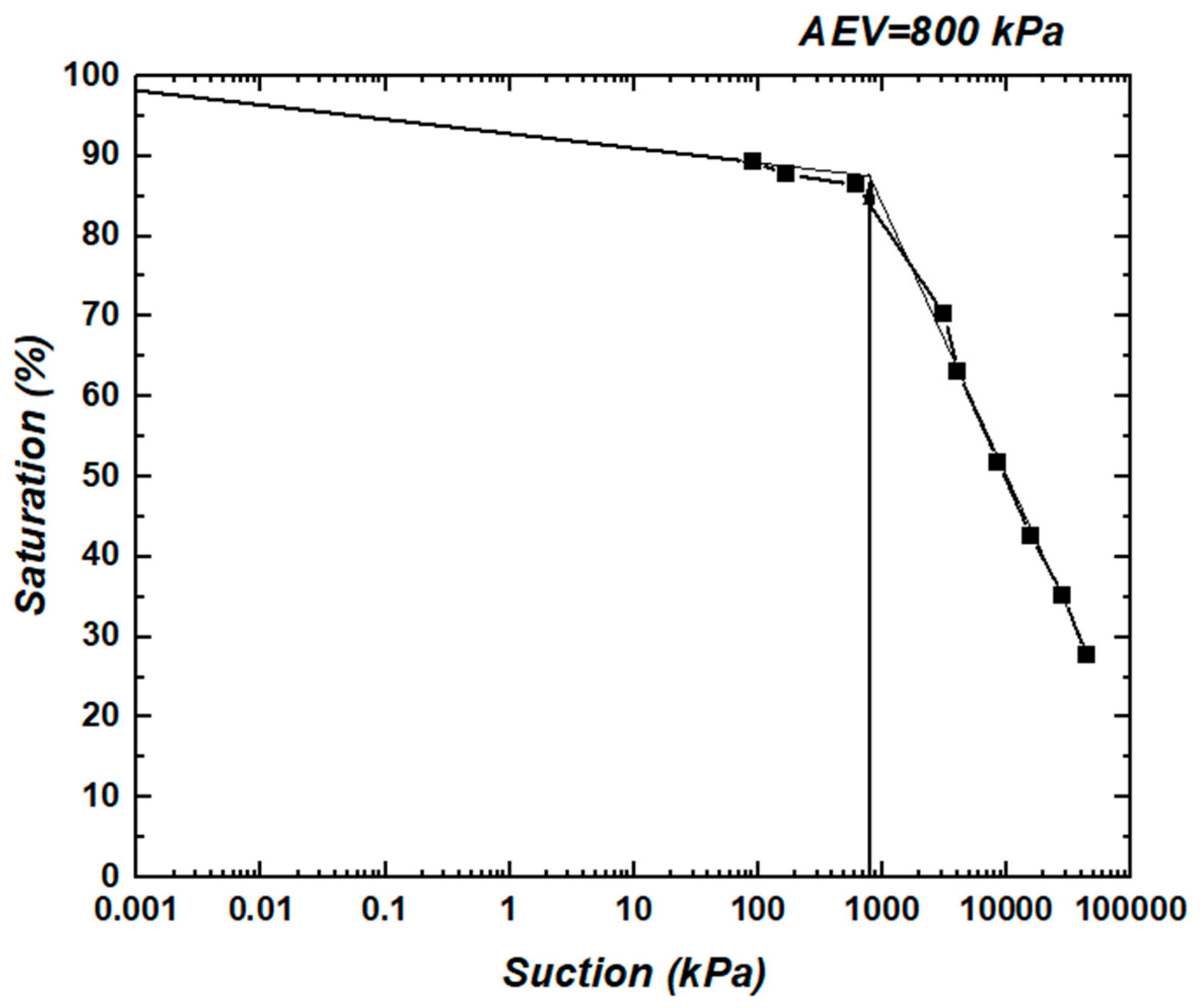
Figure 5.
Torsional ring shear apparatus: (a) control group Bromhead ring shear apparatus; (b) modified porous stones used in this study.
Figure 5.
Torsional ring shear apparatus: (a) control group Bromhead ring shear apparatus; (b) modified porous stones used in this study.
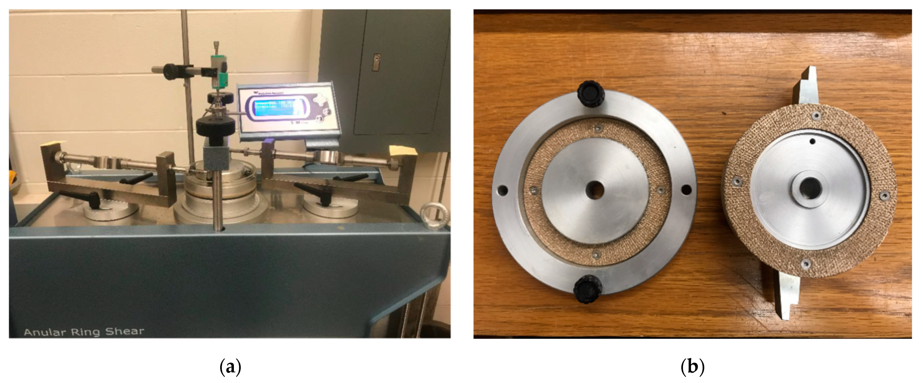
Figure 6.
Shear stress versus displacement curves for three ring shear tests performed at normal stresses of 21, 76 and 149 kPa, respectively.
Figure 6.
Shear stress versus displacement curves for three ring shear tests performed at normal stresses of 21, 76 and 149 kPa, respectively.

Figure 7.
Saturated residual and fully softened shear strength parameters estimated by linear (solid lines) and power fits (dashed lines).
Figure 7.
Saturated residual and fully softened shear strength parameters estimated by linear (solid lines) and power fits (dashed lines).
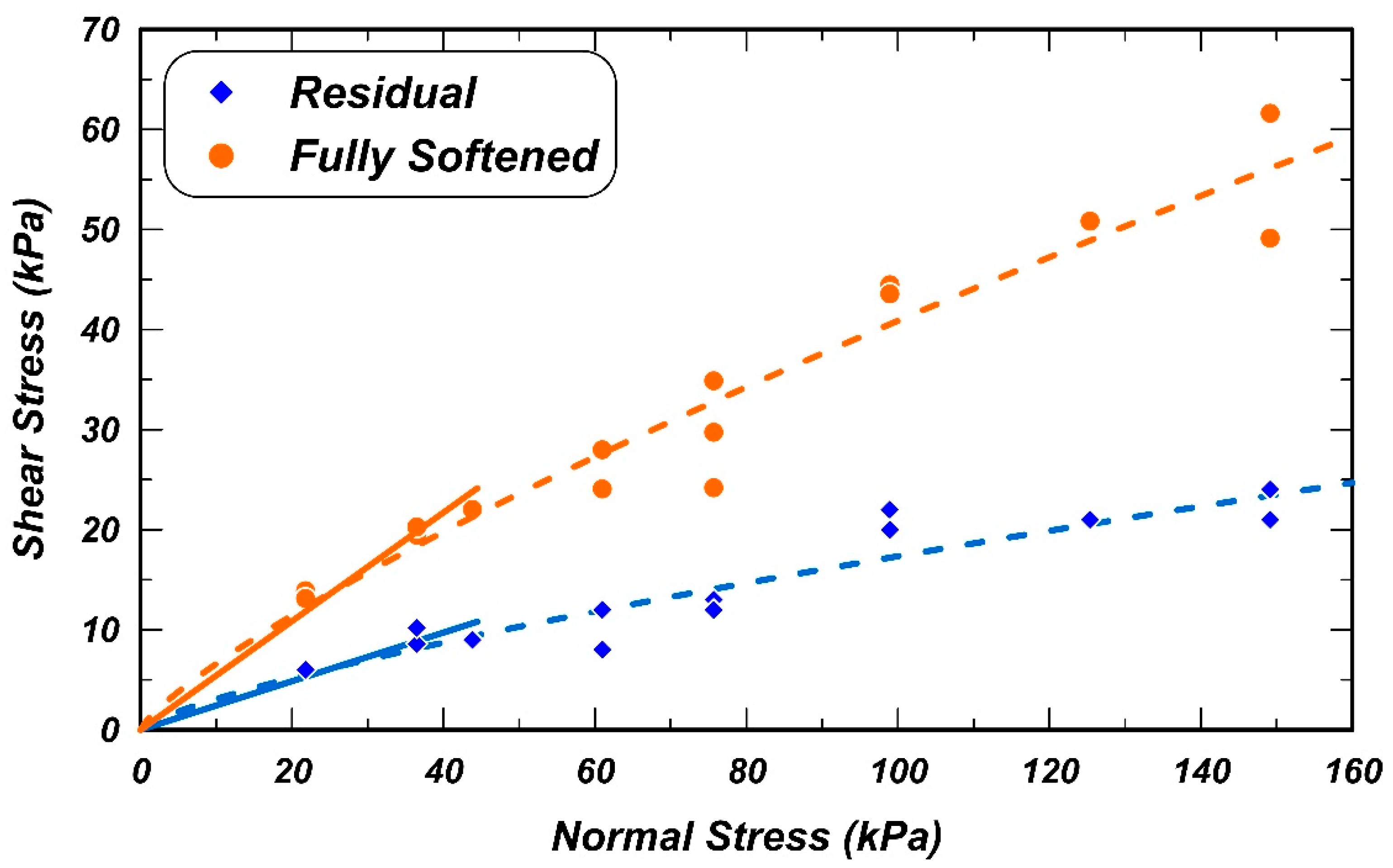
Figure 8.
Comparison of the data from this study with previous studies for both fully softened and residual shear strengths [17,18,20].
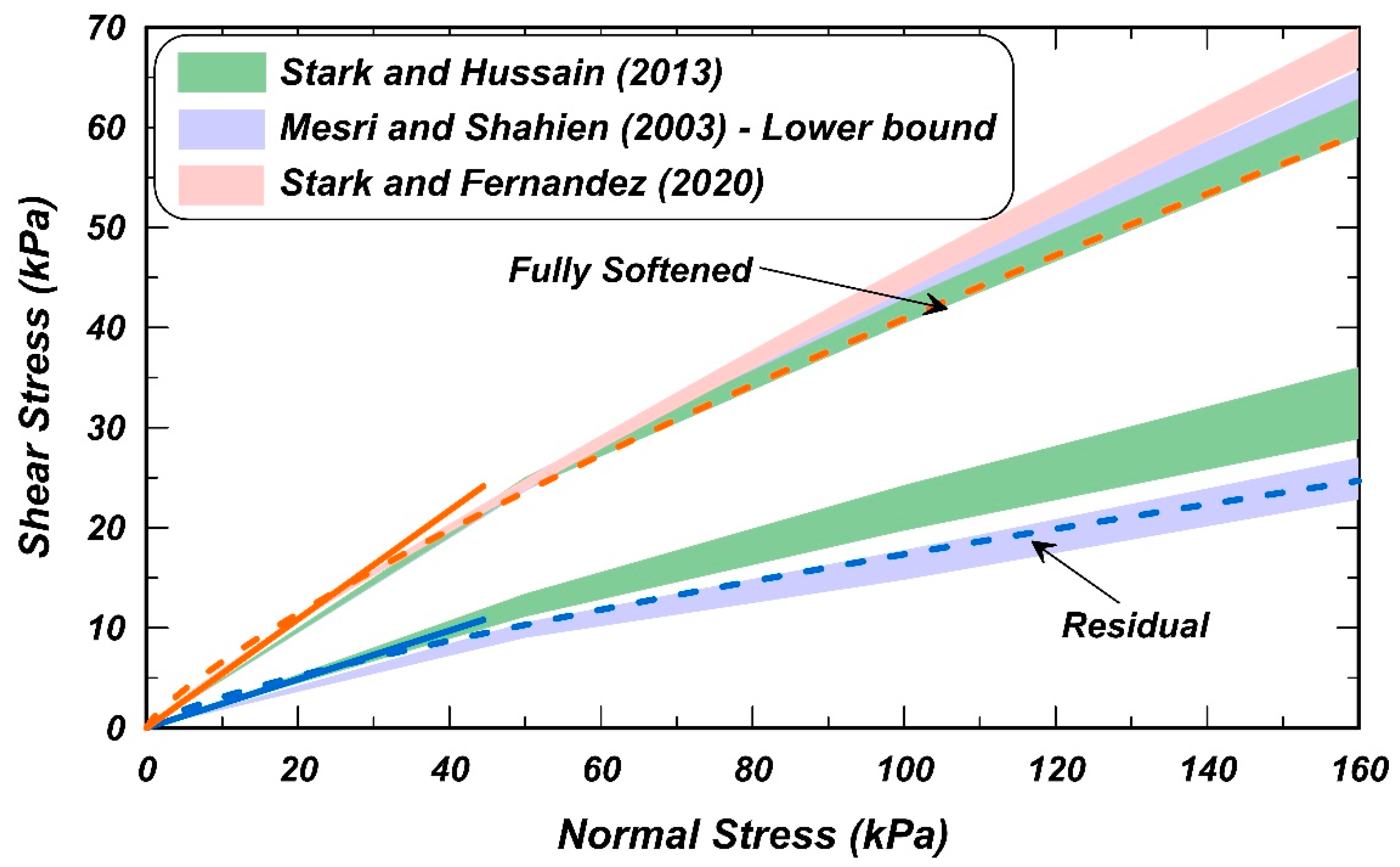
Figure 9.
Cross-section of AL-5 at borehole B5.5.
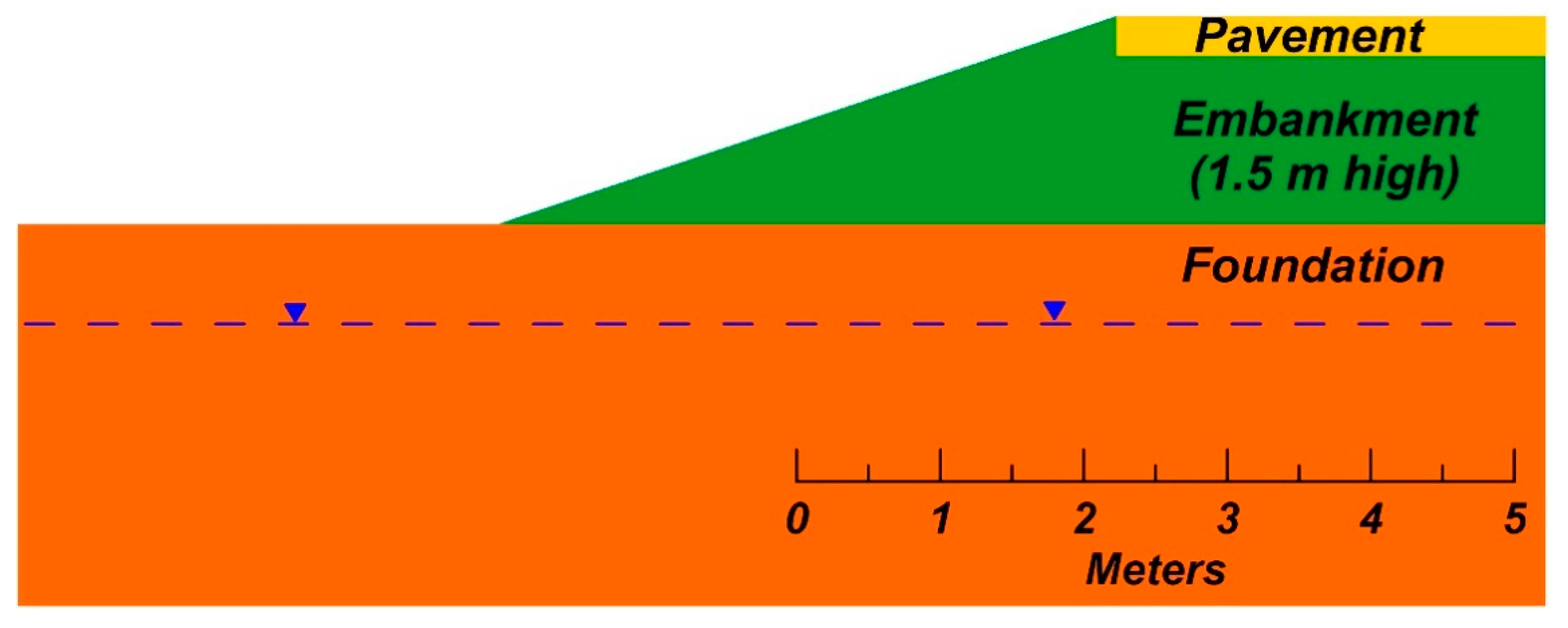
Figure 10.
Slip surface for the residual shear strength estimated by the linear envelope without suction and a 0.5 m minimum depth constraint.
Figure 10.
Slip surface for the residual shear strength estimated by the linear envelope without suction and a 0.5 m minimum depth constraint.

Figure 11.
Slip surface for the residual shear strength estimated by the power envelope without suction.
Figure 11.
Slip surface for the residual shear strength estimated by the power envelope without suction.
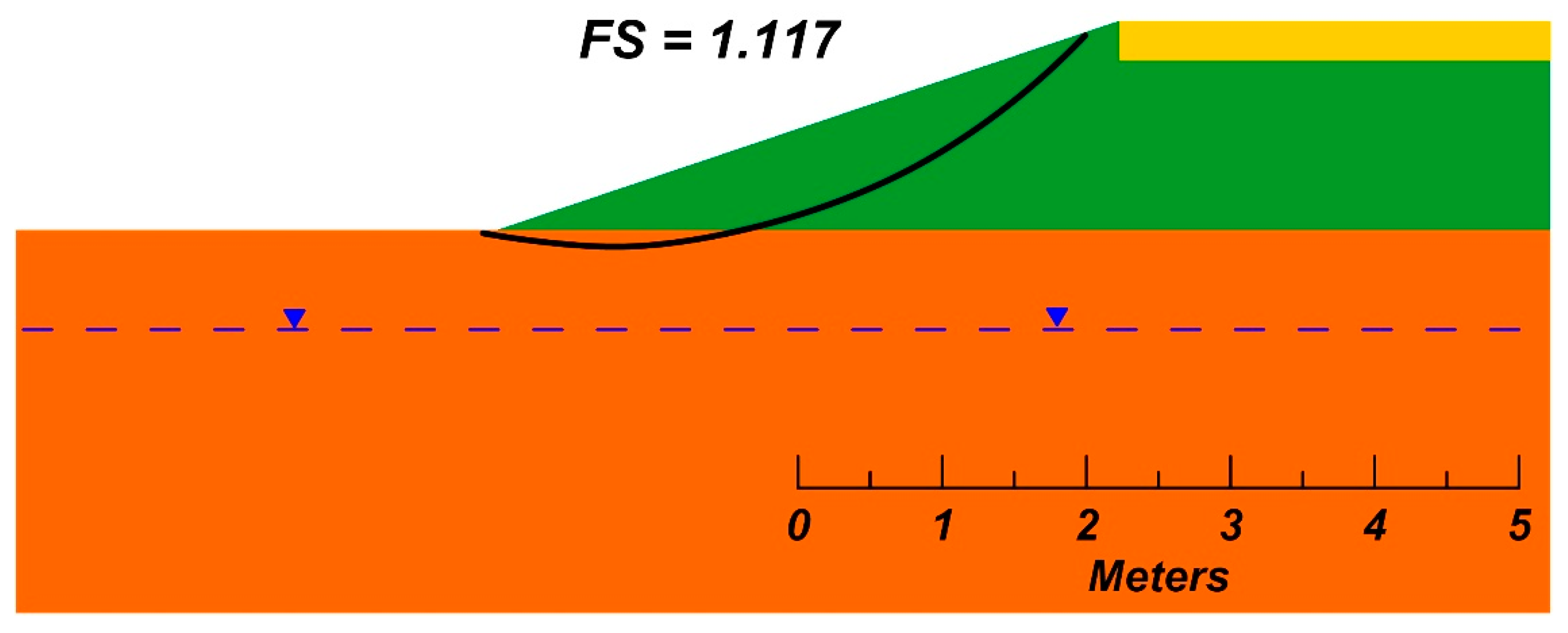
Figure 12.
Comparison of mobilized shear stress along the failure surface shown in Figure 10 with the residual strengths from the linear and power fit envelopes.
Figure 12.
Comparison of mobilized shear stress along the failure surface shown in Figure 10 with the residual strengths from the linear and power fit envelopes.
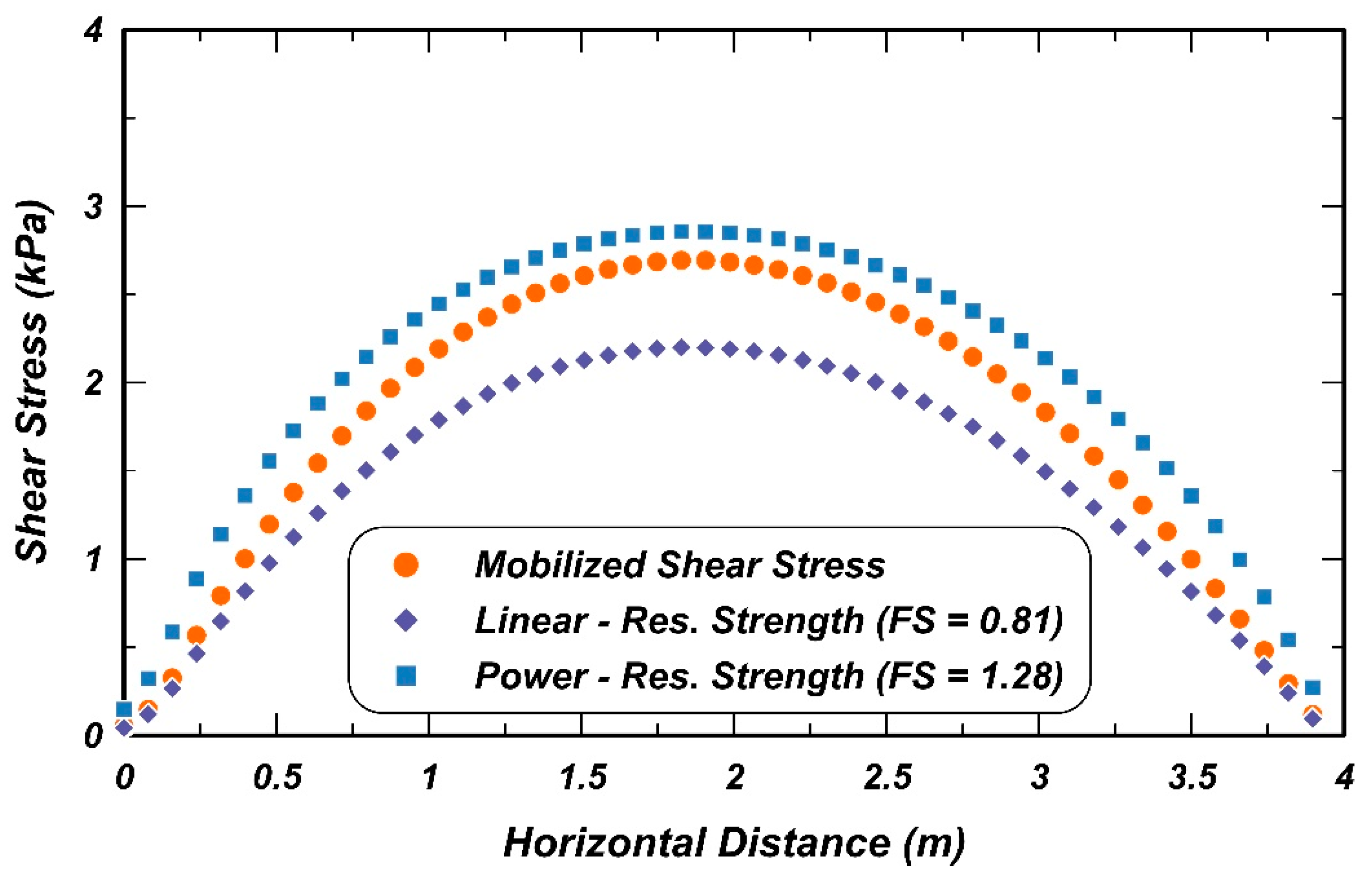
Figure 13.
Suction values in the slope stability analyses and in-situ suction measurements from borehole sensors near the edge of pavement.
Figure 13.
Suction values in the slope stability analyses and in-situ suction measurements from borehole sensors near the edge of pavement.

Figure 14.
Critical slip surface for the back-analyzed shear strength by the linear envelope with suction.
Figure 14.
Critical slip surface for the back-analyzed shear strength by the linear envelope with suction.


Table 1.
Index Properties of the Prairie Clay at Study Location [2].
Table 1.
Index Properties of the Prairie Clay at Study Location [2].
| Soil Type (USCS) | Liquid Limit | Plasticity Index | Natural Water Content (%) | Dry Density (kN/m3) | Fines Content (%) | Average Clay Fraction (%) |
|---|---|---|---|---|---|---|
| Fat Clay (CH) | 71–86 | 47–60 | 28–40% | 12.7–14.2 | 60–96% | 54% |
Table 2.
Saturated shear strength envelopes.
| Envelope Types | Strength Envelope (kPa) | R2 |
|---|---|---|
| Residual Strength-Linear Fit | 0.983 | |
| Residual Strength-Power Fit | 0.875 | |
| Fully Softened Strength-Linear Fit | 0.994 | |
| Fully Softened Strength-Power Fit | 0.929 |
Table 3.
Summary of shear strength parameters for slope stability analyses.
| Soil Layer | Density (kN/m3) | Drained Friction Angle (Deg) | Cohesion (kPa) |
|---|---|---|---|
| Pavement | 22.8 | 34 | 369 |
| Embankment | 18.1 | Fully softened and residual strength envelopes shown in Table 2 | |
| Foundation | 18.3 | Fully softened and residual strength envelopes shown in Table 2 | |
Table 4.
Summary of minimum factors of safety for the different strength envelopes.
| Factor of Safety | ||||
|---|---|---|---|---|
| Fully Softened Strength-Linear Fit | Fully Softened Strength-Power Fit | Residual Strength-Linear Fit | Residual Strength-Power Fit | |
| No suction | 1.629 | 2.344 | 0.726 | 1.117 |
| No suction—0.5 m minimum depth | 1.819 | 2.344 | 0.810 | 1.117 |
| With suction | 3.320 | - | 1.480 | - |
Publisher’s Note: MDPI stays neutral with regard to jurisdictional claims in published maps and institutional affiliations. |
© 2021 by the authors. Licensee MDPI, Basel, Switzerland. This article is an open access article distributed under the terms and conditions of the Creative Commons Attribution (CC BY) license (https://creativecommons.org/licenses/by/4.0/).
Share and Cite
MDPI and ACS Style
Xuan, M.; Montgomery, J.; Anderson, J.B. Examining the Effects of Suction and Nonlinear Strength Envelopes on the Stability of a High Plasticity Clay Slope. Geosciences 2021, 11, 449. https://doi.org/10.3390/geosciences11110449
AMA Style
Xuan M, Montgomery J, Anderson JB. Examining the Effects of Suction and Nonlinear Strength Envelopes on the Stability of a High Plasticity Clay Slope. Geosciences. 2021; 11(11):449. https://doi.org/10.3390/geosciences11110449
Chicago/Turabian StyleXuan, Mengwei, Jack Montgomery, and J. Brian Anderson. 2021. "Examining the Effects of Suction and Nonlinear Strength Envelopes on the Stability of a High Plasticity Clay Slope" Geosciences 11, no. 11: 449. https://doi.org/10.3390/geosciences11110449
Note that from the first issue of 2016, this journal uses article numbers instead of page numbers. See further details here.