1. Introduction
In recent years, increasingly stringent emissions regulations had a huge impact on the automotive industry, especially on powertrain development [
1]. To reduce fuel consumption and emission of vehicles, academical, and industrial researches focus on the development of hybrid, electrical, alternate-fuel cars, and the required infrastructure [
2]. Simultaneously, optimization of the motor’s operation through advanced shifting strategies is also an area of interest for many researchers.
In [
3], a Dynamic Programming (DP)-based optimal gear shifting control strategy is proposed for a vehicle equipped with a Power-Shift Automated Manual Transmission (AMT). To optimize the shift schedule for a hybrid electric vehicle (HEV), in [
4], also a Dynamic Programming-based optimization algorithm is presented. Both strategies managed to improve the efficiency of the system and reduce fuel consumption by approximately 11%, while [
5] shows that heavy-duty trucks allowing neutral gear can further reduce fuel consumption to 13%. A combination of Dynamic Programming and Pontryagin’s minimum principle is presented in [
6] to control the gearshift command optimally. The proposed algorithm vastly outperforms the standard dynamic programming solutions in terms of computational efficiency without loss of accuracy. To present a suitable solution for real-time applications [
7] deals with the control problem through a Model Predictive Control (MPC). In [
8], the gear shift is addressed as a hybrid optimal control problem and solved by a numerical optimization method. Besides gearshift optimization strategies, researches also focus on clutchless transmission systems and uninterrupted power flow. In [
9], an optimal robust speed synchronization strategy is introduced to improve the shifting quality, while in [
10] the gear change of clutchless electric vehicles is achieved by using Sliding Mode Control (SMC). The applied topology also affects emission, hence in [
11] different topologies are compared, including a hybrid topology, which significantly reduces CO
emission for continuously variable transmission (CVT) systems.
Gear shifting strategies have a significant effect on fuel consumption and emission, while they also have an impact on passenger comfort, which is also affected by the low-level control of clutch and gearbox actuators. In heavy-duty vehicles, the used actuators are mostly pneumatic actuators, which have many advantages over electro-mechanical and hydraulic actuators. However, due to their nonlinear behavior, modeling and controlling them is a complicated task. A detailed overview of modeling and control of pneumatic drives is presented in [
12].
Most of the related literature deals with clutch actuators, as the force of the diaphragm spring is highly nonlinear, which further complicates the control design. However, due to the similarities between gearbox and clutch actuators, studying the control of clutch actuators helps to find adequate control methods also for gearbox actuators. A wide range of methods is proposed in the related literature to achieve the position control of these systems, such as Model Predictive Controllers, Sliding Mode Control, and nonlinear backstepping controllers. In [
13], an explicit MPC method is combined with using Pulse-Width Modulation (PWM). In [
14], an SMC controller is designed, while the possibility of controller reduction is also presented. In [
15,
16], cascaded tracking controllers are developed, which combine nonlinear controller (a sliding mode controller and a model-based backstepping controller) with Lyapunov techniques based on a nonlinear state-space representation. In [
17], a switched backstepping controller is proposed, which has improved performance and less solenoid valve switches than PWM-based methods. In [
18], a dual-mode controller is developed by combining a local and a global switched controller. Robust control techniques are also proposed, such as [
19], where the control problem is formulated as a robust asymptotic tracking control problem. The control problem is solved using Simulated Annealing Techniques. To achieve high tracking performance, presents a H∞ controller [
20].
On the contrary, gearbox actuators do not have significant counter-force, hence mostly Linear Time-Invariant (LTI) and open-loop controllers are used. An example is shown in [
21], where an LQ servo method is proposed to control the gearbox actuator. However, there are further differences between pneumatic clutch- and gearbox actuators, such as the system dynamics and the type of the solenoid valves. Gearbox actuators have faster dynamics, and in most cases, 3-way 2-position (3/2) valves are used instead of 2-way 2-position (2/2) valves to minimize the cost. 3/2 valves either load or exhaust the connected chamber. Thus they cannot hold constant pressure, which results in an unstable system. Hence, pneumatic gearbox actuators are stabilized in their dedicated positions (gears) by mechanical constraints.
While depending on the application, pneumatic actuators can be controlled either by nonlinear or LTI methods, pneumatic systems can also be formulated as Linear Parameter Varying (LPV) systems. LPV control design is a widely used approach for modeling and control a special class of nonlinear systems. LPV approach is widely used in many vehicle-related applications, for instance, in suspension systems. In [
22], an active suspension system is modeled and controlled using an LPV-based approach, while in [
23] a new control strategy is introduced to control a semi-active suspension. The proposed strategy a priori satisfies the principal limitations of the actuator. In [
24], the semi-active suspension system is modeled as a polytopic LPV model, then a H∞ controller is applied. In [
25], a variable-geometry suspension is controlled through an LPV controller, while the construction system is also taken into consideration. Furthermore, LPV approach is also used in driver assistance systems, such as adaptive cruise control (ACC) [
26], anti-lock braking systems (ABS) [
27,
28], steering control [
29] and the integrated control of these systems [
30,
31]. Further application examples include freeway traffic modeling [
32], wind turbine control [
33] and Air–Fuel ratio control of spark ignition engines [
34]. In [
35], a pneumatic positioning system is formulated as a polytopic LPV model, while [
36] deals with the quasi-LPV (qLPV) control of the pneumatic system of an aircraft. Besides, the nonlinearities of the pneumatic system, the presented actuator contains a floating piston with a limited movement range. This means the actuator has two discrete state-space representations, which can be easily handled by an LPV representation. Therefore, in this paper, a detailed LPV model of the floating piston pneumatic actuator is created, then an LPV-based H∞ control design is presented to achieve the position control of an electro-pneumatic gearbox actuator.
The initial design of the LPV-based control for the system is presented in [
37]; however, the results are only evaluated on simulation with a simplified model. This paper further develops this design, by using a slightly different generalized model, applying different LPV synthesis, and performing order reduction on the system to be implementable. Furthermore, the measurements on a real heavy-duty gearbox and comparison to other methods are presented.
Contributions of the Paper
In this paper, a grid-based qLPV model of an electro-pneumatic actuator is presented. Furthermore, an LPV/H∞ controller is designed as a set-values controller to achieve the position control of the actuator. The controller is tested in a Model in the Loop (MIL) environment, then it is implemented on the real target. Based on the results, the proposed method can handle fast changes in the actuator behavior, hence it can be extended to other pneumatic actuators.
The paper is organized as follows:
Section 2 introduces the pneumatic actuator and presents the nonlinear model used for simulation tests.
Section 3 shows the LPV-model of the actuator and the LPV controller design.
Section 4 presents the simulation results and
Section 5 presents the measurement results.
Section 6 shows some conclusion remarks.
2. System Description
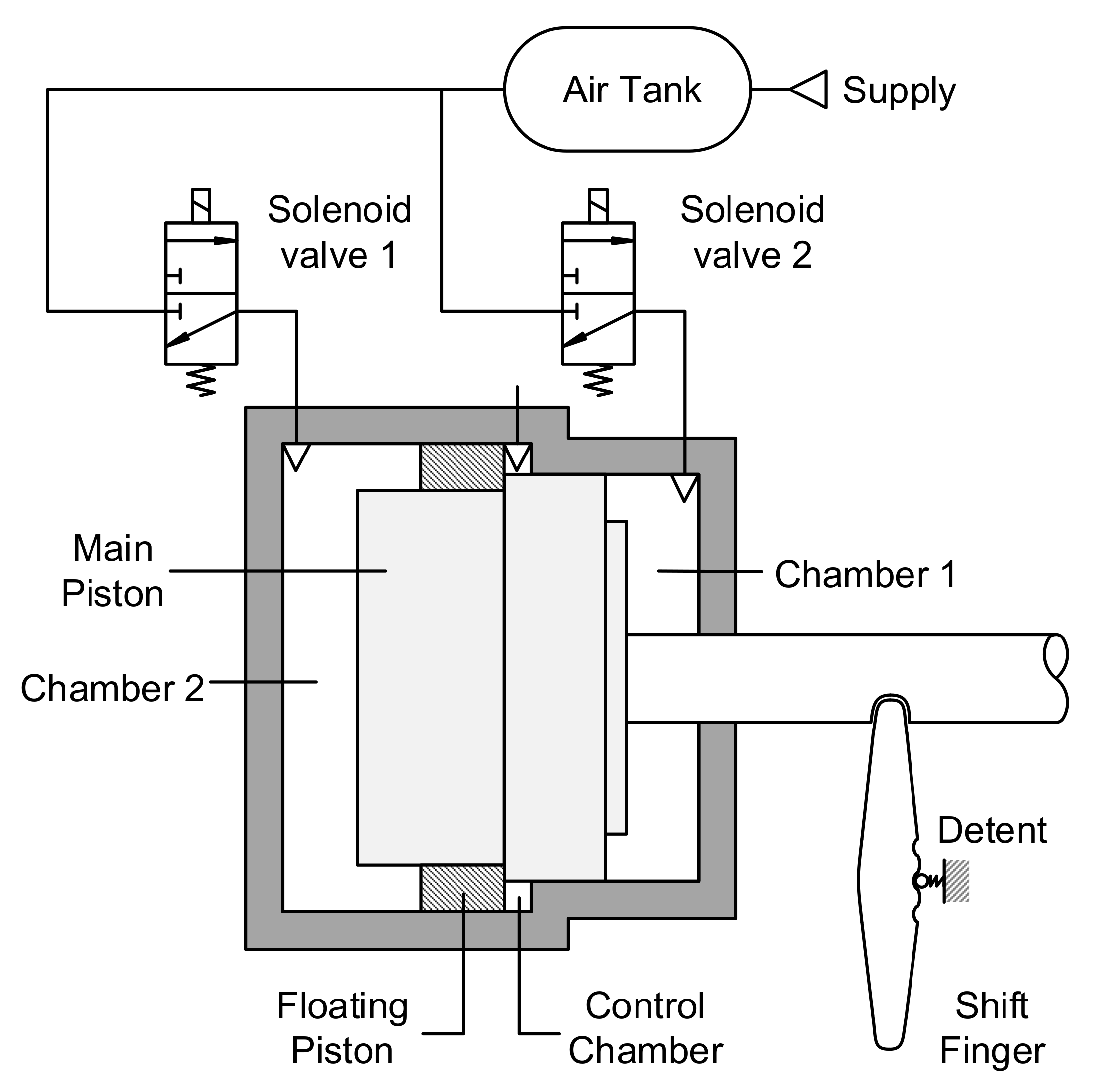
The examined gearbox actuator is a shift actuator, shown in
Figure 1. It consists of a double-acting floating-piston cylinder, a shift finger, a detent mechanism, and two 3-way 2-position solenoid valves. The actuator needs to switch between the two end positions of the cylinder, namely High (H) and Low (L), and an intermediate position, Neutral (N). The gear change is achieved by the Main Piston, as it is connected to the face-dog clutches in the gearbox through the shift finger and the gearbox linkage. On both sides of a face-dog clutch, there is a gearwheel connected to the shaft or rotates freely. In High and Low position, the face-dog clutch connects the required gearwheel to the shaft in a shape-locking connection to achieve torque-flow, while in Neutral both gearwheels rotate freely.
The solenoid valves realize position control of the Main Piston. In the released state, they connect Chamber 1 and Chamber 2 to the environment, while in the activated state, they connect them to the pressure supply. For optimal gear change, asymmetric piston areas are needed, but depending on the requested gear change, different area ratios between the two sides of the Main Piston are optimal. To shift the gear from High to Neutral, the left side of the piston should have a bigger cross-section area, while in case of Low to Neutral gear change, the right side piston area should be bigger. To ensure both conditions, the actuator contains a Floating Piston. The movement of the Floating Piston is limited to the Neutral–High interval of the cylinder, hence it helps gear shifts by modifying the area ratio in one side of the cylinder.
The Floating Piston also defines a third chamber, called Control Chamber, within the cylinder. The Floating Piston tunes its volume and its pressure, thus it reacts to the movement of the Floating Piston, while it also affects the motion of the Main Piston. To prevent the Main Piston’s undesired movement and to guarantee stability in the dedicated positions, a detent mechanism is used to fixate the piston in these positions. The detent mechanism is designed to move the piston towards the nearest dedicated position, but its force is negligible compared to the actuating force of the actuator, thus it does not affect the gear change significantly.
First, to provide an environment, where the developed controllers can be tested, a more detailed, nonlinear model has been developed in [
38]. The model has been verified and validated against measurements, which has been presented in [
39]. By quantifying the modeling accuracy as the root mean square (RMS) of the errors, the model’s accuracy is above 95% for all validated outputs.
3. LPV Controller Design
The controller design aims to achieve the requested gear change by controlling the position of the Main Piston. There are four possible gear changes: Neutral to Low, Low to Neutral, Neutral to High, and High to Neutral. Low to High and High to Low gear changes might also be requested; however, they are divided into two sequential gear changes through Neutral.
Besides reaching the actuator’s requested state, the controller must meet the following qualitative requirements, while the control and measurement frequency is limited to 1 kHz:
Maximum 80 ms shift time;
Maximum 0.2 m/s impact velocity at reaching the end positions of the cylinder;
Maximum 1 mm (around 10%) overshoot and amplitude when reaching Neutral state;
Maximum 6 solenoid valve actuation.
Minimizing the shift time is crucial, as the longer the gear shift takes, the longer the power flow is interrupted, which affects negatively both passenger comfort and vehicle dynamics. Assuming a manual transmission, a gear shift takes approximately 0.5–1 s for an average human driver. The shift consists of the clutch’s disengagement, the gear shifting with synchronization, and the clutch’s engagement. Most of this time is needed for the operation of the clutch, hence the shift time must be under 80–100 ms. Ideally, there would be no collision between the cylinder housing and the piston, however, as the system is only stable in its fixed positions, hitting the end positions is unavoidable while switching to High or Low. Hence, the collision speed and the kinetic energy at the moment of collision must be minimized to prevent the damaging of the system. To determine the limit of the impact velocity, in most cases finite-element modeling and lifetime calculations are used. The limit of the overshoot is a safety-critical requirement, as accidental gear changes caused by overshoot must be avoided to ensure safe operation. Since the actuator shall operate on different gearboxes, the exact positions of the gears are not known, hence the strict limitation is reasonable. The number of the maximum valve activations is a less strict criterion, and a slight excess of this limit can be tolerated, but it excludes widely used methods, such as PWM. It is calculated from the valve switches guaranteed for the valve’s lifetime, the actuator’s expected lifetime, and the assumed number of gear changes during the lifetime of the system. The ECU limits the maximum control frequency as further reducing the sample time could cause malfunction because the tasks could overlap as the ECU cannot finish the calculations before the start of the next step.
3.1. Introduction to LPV Systems
Linear Parameter-Varying systems are a particular class of nonlinear systems, which are modeled as linear state-space representations whose state matrices depend on a set of time-varying parameters, called scheduling parameters:
where
is the state vector,
is the output vector,
is the input vector,
is the vector of scheduling parameters, and
A,
B,
C, and
D are parameter dependent matrices of the state-space representation.
There are several methods to represent the parameter dependence of LPV systems, such as Linear Fractional Representation (LFR), polytopic models, and grid-based LPV models. In the case of LFR models, Linear Fractional Transformation (LFT) is used to separate the nonlinearities of the system (such as the time-varying parameters and uncertainties) from the nominal, Linear Time-Invariant (LTI) part of the system. However, it can be used only in the case of rational parameter dependence. Polytopic models are often used to describe affine LPV systems, where the vector of parameters evolves inside a polytope, hence it is written as a convex combination of the polytope’s vertices. Grid-based LPV models divide the parameter domain into a grid of parameter values, then specify the linear dynamics at each grid point through Jacobi linearization. As they capture the system’s parameter dependence implicitly, they can handle any parameter representation, hence the grid-based representation is an ideal choice to consider the discrete change in the state-space, which is caused by the floating piston. Therefore, for modeling the actuator as an LPV system, a grid-based representation has been implemented.
Depending on the scheduling parameters, LPV systems are divided into two types: the parameters are either external (exogenous) variables, then the system is non-stationary, or they are functions of the state variables (endogenous variables), then the system has nonlinear dynamics. LPV systems with endogenous parameters, such as the presented pneumatic actuator, are also called quasi-LPV (qLPV) systems.
3.2. Detailed qLPV Model
In the case of the most widely used representations of pneumatic actuators, the state vector consists of the chamber pressures and the piston’s position, velocity, and in some cases, its acceleration. However, these formulations neglect the heat transfer of the chambers. To represent the nonlinear model as accurately as possible in the form of a qLPV model, the heat transfer shall be taken into account, for which the chamber temperatures must be calculated. Hence, including the state vector’s temperature would be evident, but it is calculated based on the ideal gas law, using the mass of air is more sensible. Therefore, the state-vector has been chosen as follows:
where
and
are the chamber pressures,
and
are the mass of air in the chambers,
is the main piston’s position and
is its velocity.
While keeping the model’s accuracy as high as possible, some simplifications must be applied to keep the number of scheduling parameters below a manageable level. To simplify the state-space representation, the valve dynamics have been neglected, hence the mass flow rates of the valves have been chosen as input signals:
The controller determines the required mass flow rates, then the discretization logic converts them into binary valve commands.
The output vector consists of the chamber pressures and the main piston’s position:
As the actuator model is input-affine, its state-space representation is written as:
where
f is the nonlinear state function,
is the ith linear input function
x is the state vector,
y is the output vector,
u is the input vector,
d is the disturbance vector, and
r is the hybrid mode mapping.
The state matrix A and input matrix B can be determined through Jacobian linearization from the nonlinear model. However, to further reduce the model’s complexity, the following simplifications have been made:
Detent mechanism is disregarded;
Contact forces between the pistons are disregarded, thus based on the main piston position, the floating piston is either in Neutral position or assumed to move together with the main piston;
Control chamber pressure is assumed to be equal to the ambient pressure;
Coulomb-friction is neglected, only the viscous term is taken into consideration.
The applied simplifications can affect the model’s accuracy on different levels. The detent mechanism prevents the gearbox from accidentally falling out of gear, but the detent force is significantly smaller than the pressure forces. Therefore, it is negligible during gear change. Simplifying the contact forces in a presented way can affect the dynamics in two cases: high-speed movement around Neutral, which is excluded by the test cases and the requirements, and if the pistons are separated between Neutral and High. To shift the gear to High, the Main Piston pushes the Floating Piston, as the latter has no contact with Chamber 1, while in the case of High to Neutral, Chamber 2 affects both pistons directly. In this case, the lower mass of the Floating Piston guarantees continuous contact. In the case of the Control chamber, only the changing volume could cause pressure change, but based on the simulations, it is insignificant regarding the pistons’ movement. Neglecting the Coulomb-friction can decrease the model’s accuracy. It has a discrete transition around zero speed, which could be linearized by using a sigmoid function, but a too steep slope leads to numerical errors, while a more gradual slope could also decrease the model’s accuracy. If needed, it can be included in the state-space representation as an uncontrolled input.
At last, after the simplifications, the state and input matrices are written as:
As (
7) shows, the state matrix includes the main piston’s velocity and the chamber volumes, while due to the simplification regarding the floating piston,
and
depend on the main piston’s position, hence they must be included in the scheduling vector. On the other hand, in
B the temperatures
and
are also scheduling parameters.
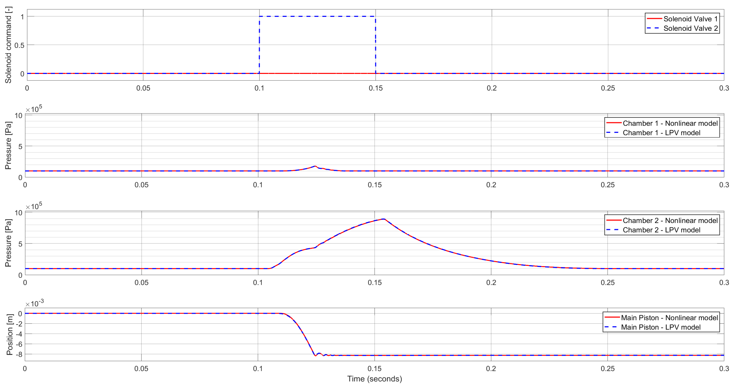
The developed LPV model has been validated against the presented nonlinear model.
Figure 2 shows the Neutral to Low gear change as an example. While the developed model can accurately describe the system’s behavior, it cannot be used for controller synthesis. The model has eight scheduling parameters, which is still easily manageable for simulation purposes, compared to the mutli-state, hybrid LTI state-space representation of the system. Although finding a feedback matrix, which stabilizes the plant while also meeting the performance requirements is very complicated, or even impossible. Besides, the implemented controller’s order also depends on the LPV model’s order. Hence it must be simplified for controller development.
3.3. Reduced-Order qLPV Model
The discretization of the continuous control signals is a crucial part of the controller design, as it has a significant effect on the controller behavior. Hence, changing the input signals of the system is an obvious choice, as it will remarkably simplify the qLPV model. By choosing the chamber pressures as input signals and modifying the discretization logic, the controller shall meet the controlling aims, while the state-space representation is simplified to the mechanical model of the actuator.
After simplification, the state-space model takes the following form:
The scheduling parameter vector contains
and
, which are scheduled according to
x as follows:
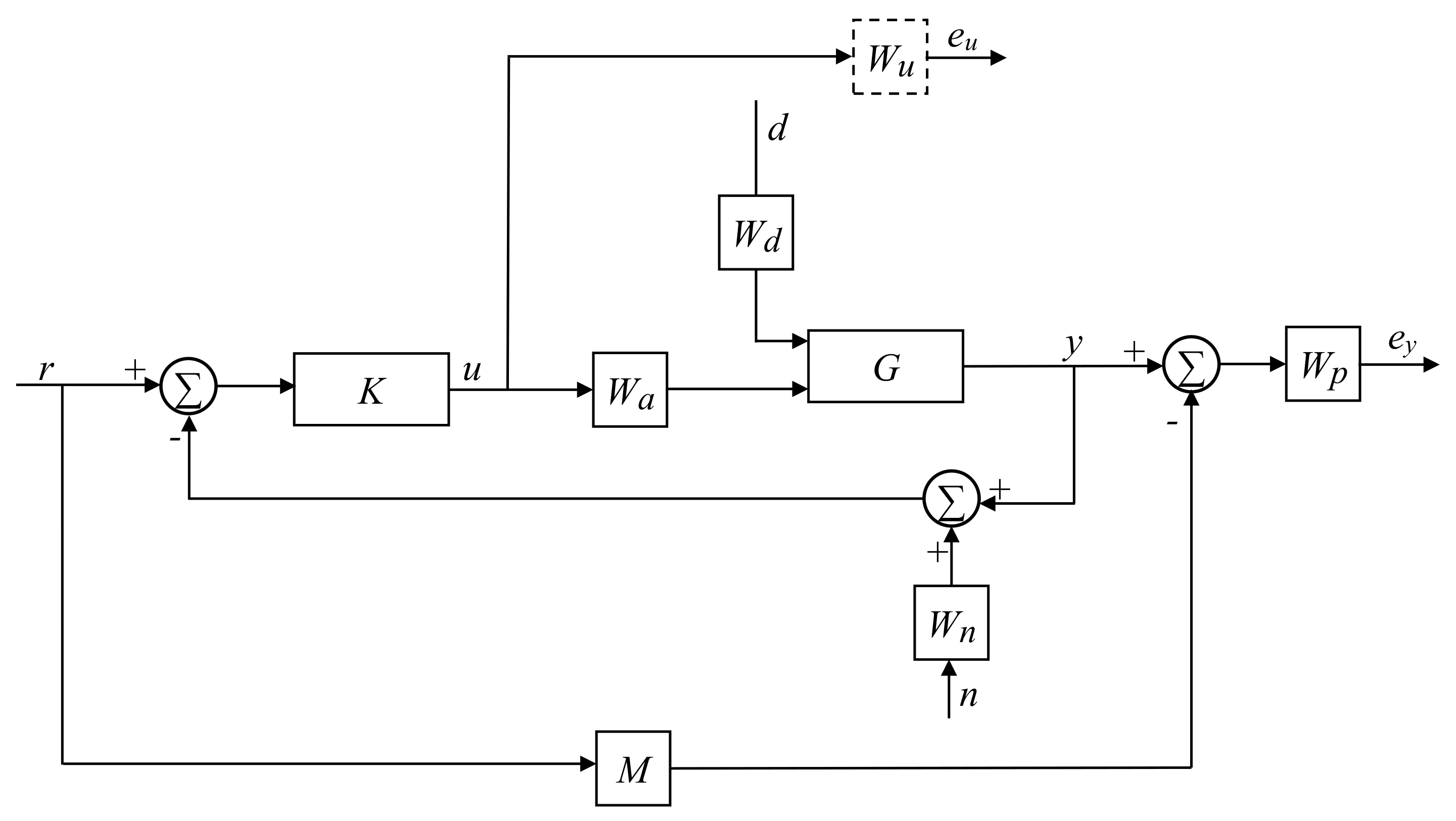
As the next step of the controller synthesis, the generalized plant must be formulated. The layout of the generalized plant is shown in
Figure 3.
The system has a reference input (n), a measurement noise (n), an input disturbance (d), and two output costs ( and ). Besides the controller (K) and the plant (G), the generalized plant contains several weighting functions representing the model’s uncertainty and performance objectives.
describes the behavior of the solenoid valves and the chamber thermodynamics. It models the increase or decrease of the chamber pressure caused by the solenoid commands. Clearly, in case of more complex cases (such as back and forth movement of the piston, or frequently changed solenoid valve commands), chamber thermodynamics cannot be modeled accurately with a Single Input Single Output (SISO) transfer function. However, the gear change shall be achieved by a single solenoid valve command over a short time. Hence, it is assumed, that the flow is choked (the pressure ratio is smaller than the critical value). Hence, the airflow rate can be assumed to be constant. If the heat transfer and the volume change is neglected, the pressure gradient is a linear function of the mass flow rate. Therefore, the pressure is calculated according to a 2nd order function:
is the control input weight. In most cases, it is chosen as a high-pass filter, which prevents actuator saturation, but in this application, the control signal must be between 0 and 1. Furthermore, based on the results of the controller tuning, there is no need for frequency-dependent weight. Hence, it is set equal to the identity matrix:
takes the sensor noise into consideration. Sensors are more accurate at low frequencies, while they perform poorly at high frequencies, thus it is modeled as a high-pass filter:
is the performance weighting function, which reflects the performance specifications of the closed-loop system. The system must have fast response time and proper reference tracking, while its overshoot (and collision speed) must be minimized. To have good reference tracking, the performance weight must have a low gain at low frequencies, while to limit overshoot a high gain is needed at higher frequencies. To find a good trade-off between these requirements, the weighting function’s cross-over frequency shall be equal to the inverse of the desired closed-loop time-constant. Based on these considerations,
can be written as:
The output costs penalize the control cost and performance error. In this case, the reference signal is a step function, which is not suitable for continuous tracking, hence
M is added to the generalized plant, which describes the ideal system response to the reference signal. This way, it introduces the time-domain requirements to the design process. It determines the piston position from the solenoid valve commands. As the pressure is a quadratic function of the mass flow rates, and the acceleration is linear to the pressures, the position shall be a quartic function. Although, we have only two requirements for each gear change, which are related to the system dynamics: shift time and either overshoot or collision speed. The overshoot and the collision speed are rather similar, and determining the coefficients of a quadratic function to meet the requirements is quite straightforward. Furthermore,
is also a trade-off between the response time and overshoot. Hence, a 2nd order system has been chosen over a 4th order system:
The inputs to the plant are the chamber pressures, but besides the mass flow rates, they are also affected by the volume change of the chambers, which must be taken into consideration. Hence, it is modeled as an input disturbance (
):
The pressure change caused by the volume change should be modeled as a transfer function, but adding dynamics to the input disturbance would increase the controller’s order, which is critical in the embedded application.
Once the generalized plant is formulated, the controller can be developed. It is widely known, that pneumatic actuators have several uncertain parameters, such as friction and contraction coefficients. It is reasonable to design a controller, which can handle these uncertainties. Therefore, an LPV/H∞ controller is synthesized, which minimizes the induced
norm of the closed-loop system. The parameter varying controller synthesis is performed by using LPVtools [
40]. Solving the controller synthesis in LPVtools consists of the following main steps:
Defining the scheduling parameters as pgrid objects;
Defining the state matrices of the grid-based LPV model using the scheduling parameters;
Combining the state matrices to form the grid-based LPV model in pss data structure;
Creating the generalized plant by defining the weighting functions and connecting them using the sysic interconnection structure of Matlab Robust Control toolbox;
Controller synthesis using; LPVsyn function of LPVtools.
Then, to convert the continuous output of the developed controller to binary values, a discretization algorithm is implemented:
where
is the output of the controller and
is a threshold value, which has different values based on the request.
4. Simulation Results
The developed controller has been tested in a Model in the Loop (MIL) environment using the presented nonlinear model.
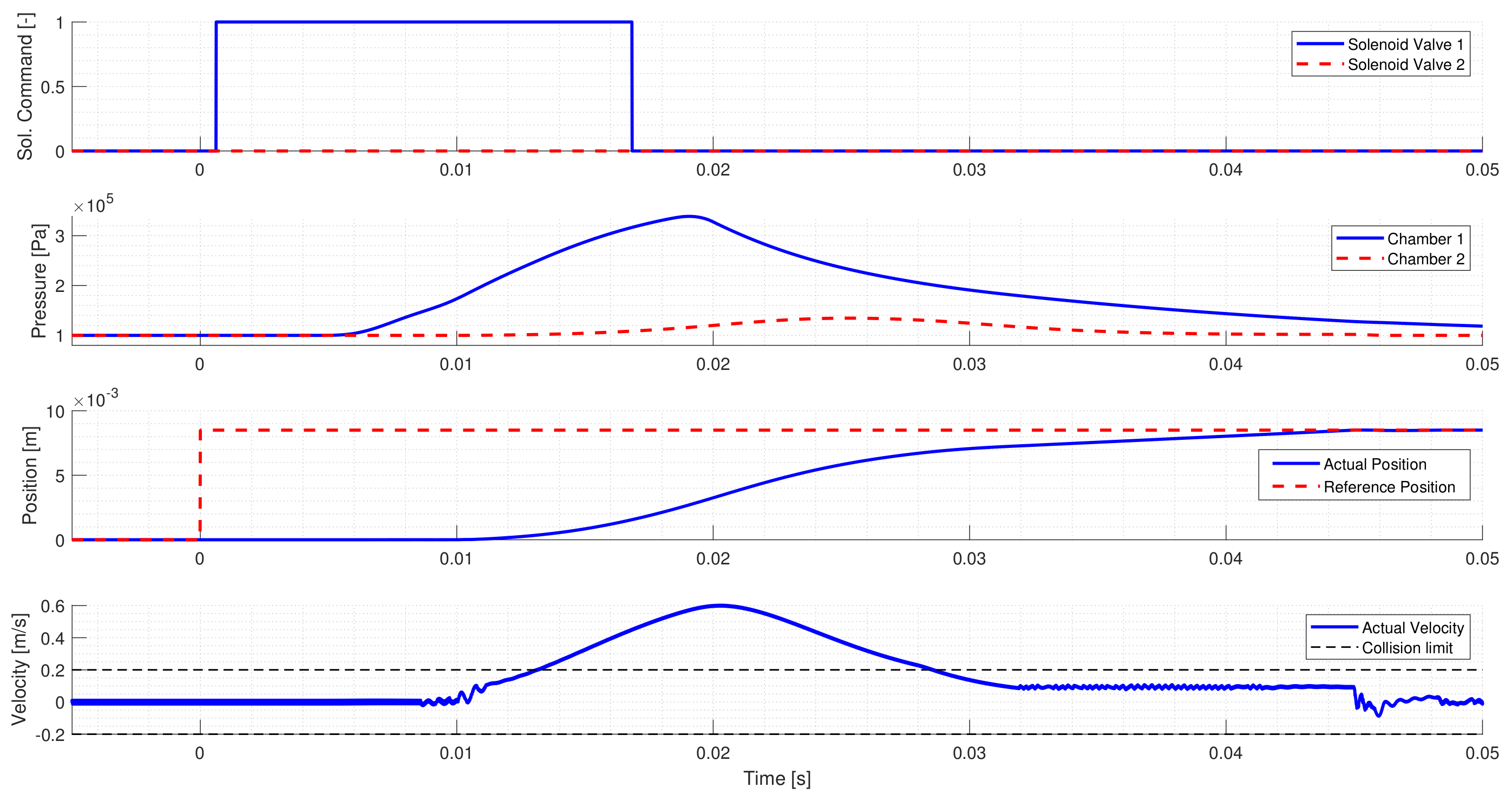
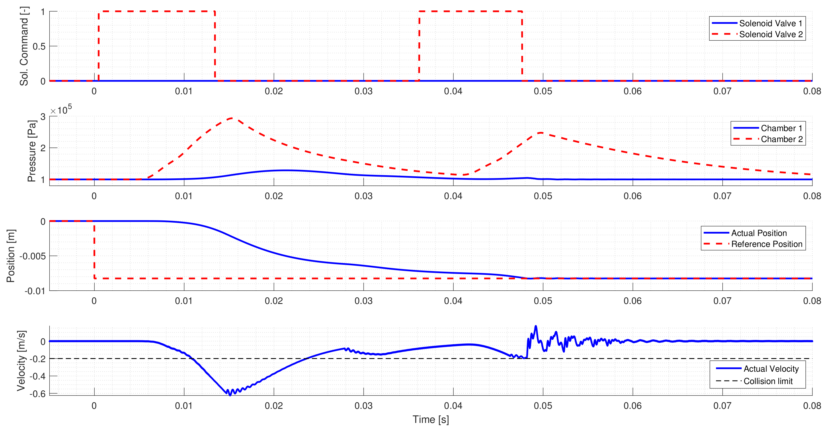
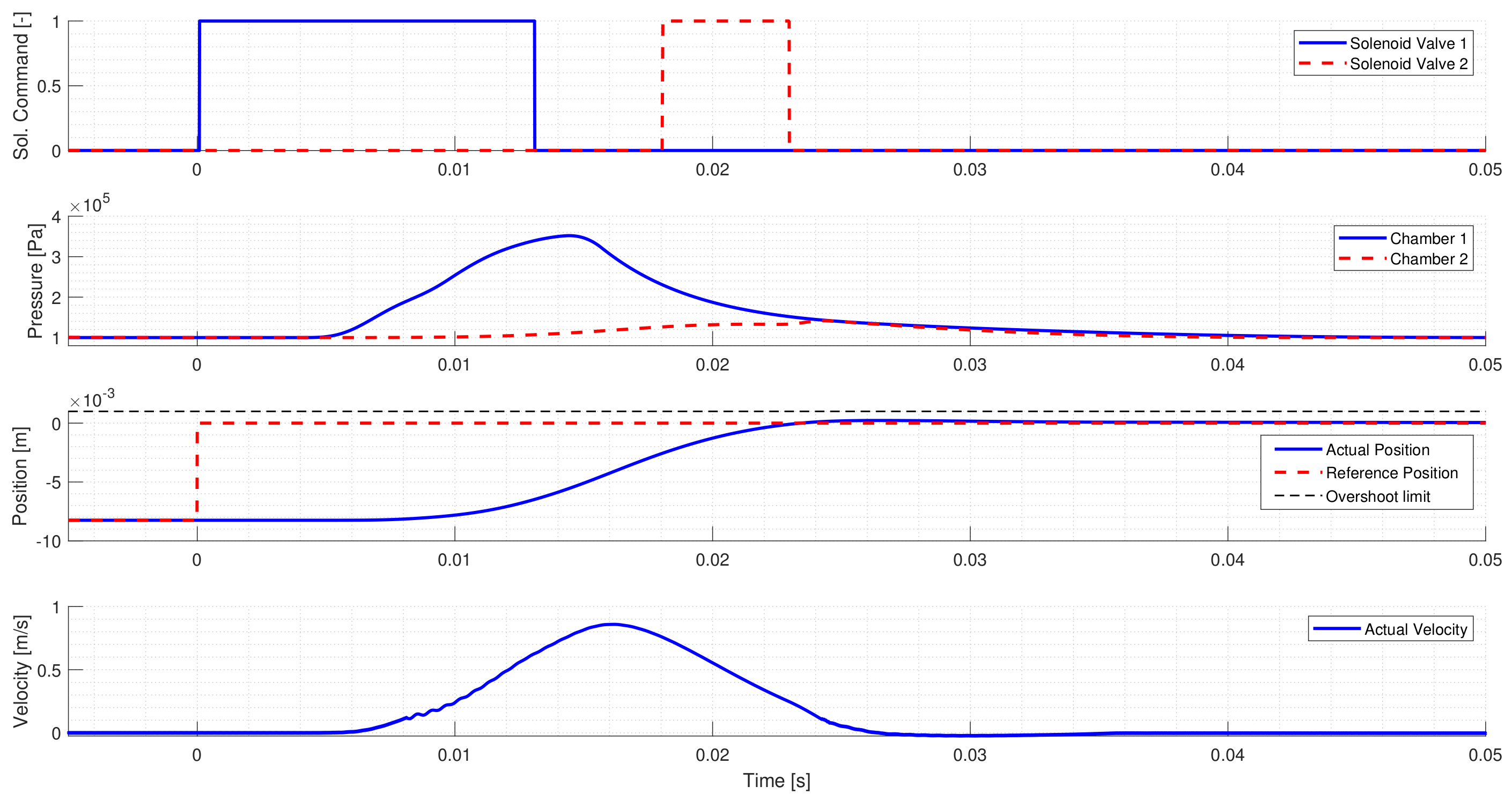
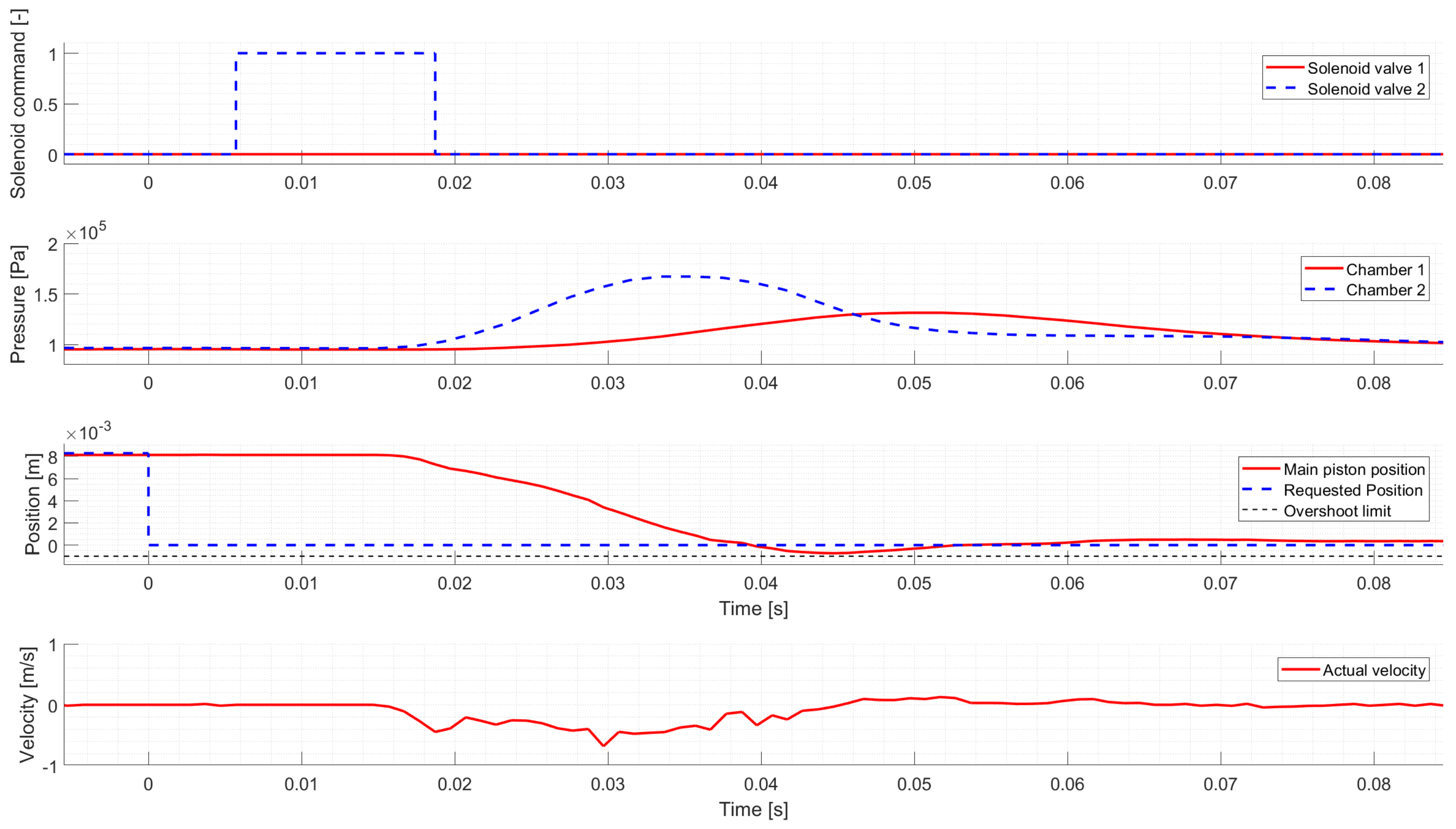
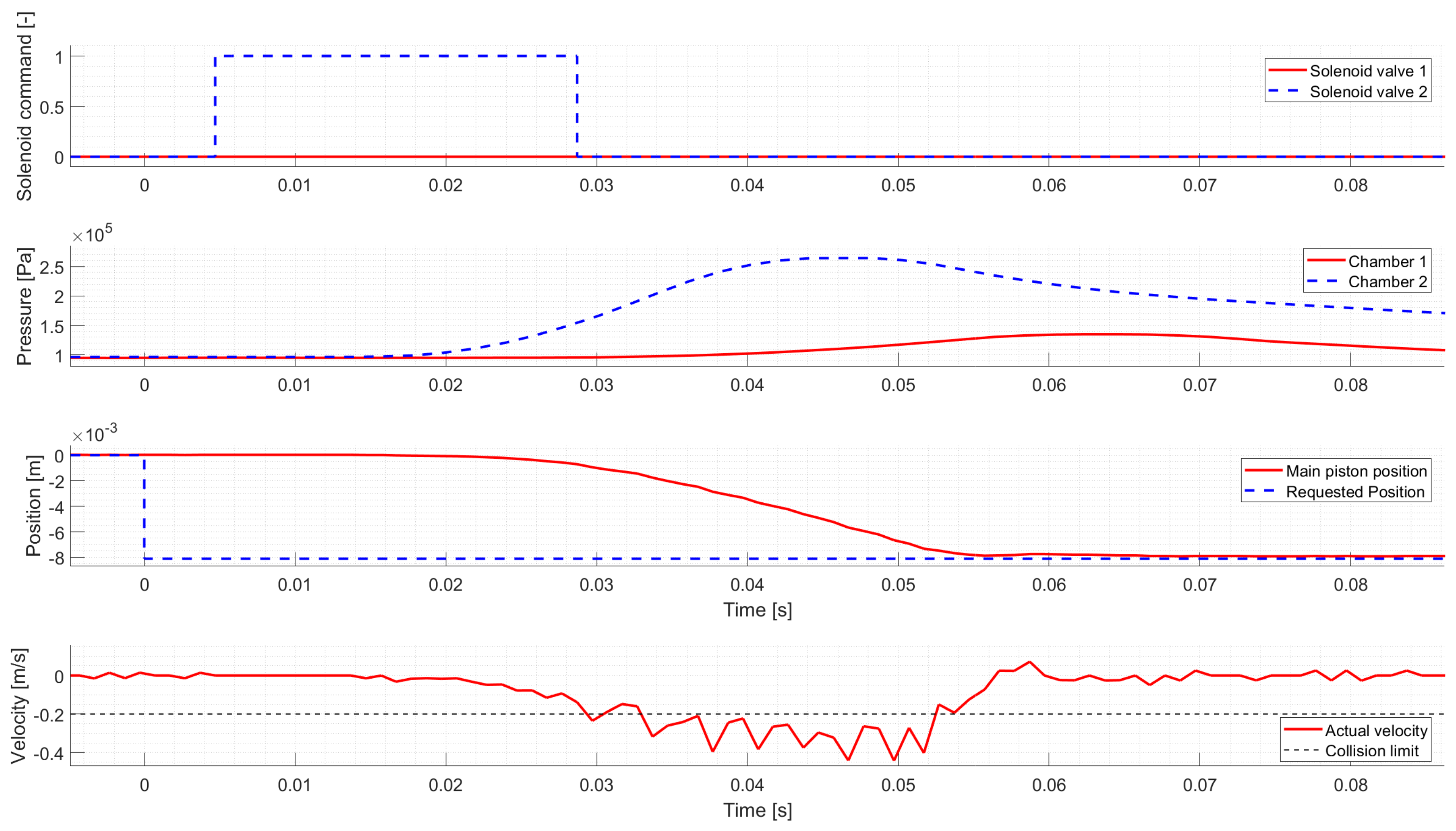
Figure 4,
Figure 5,
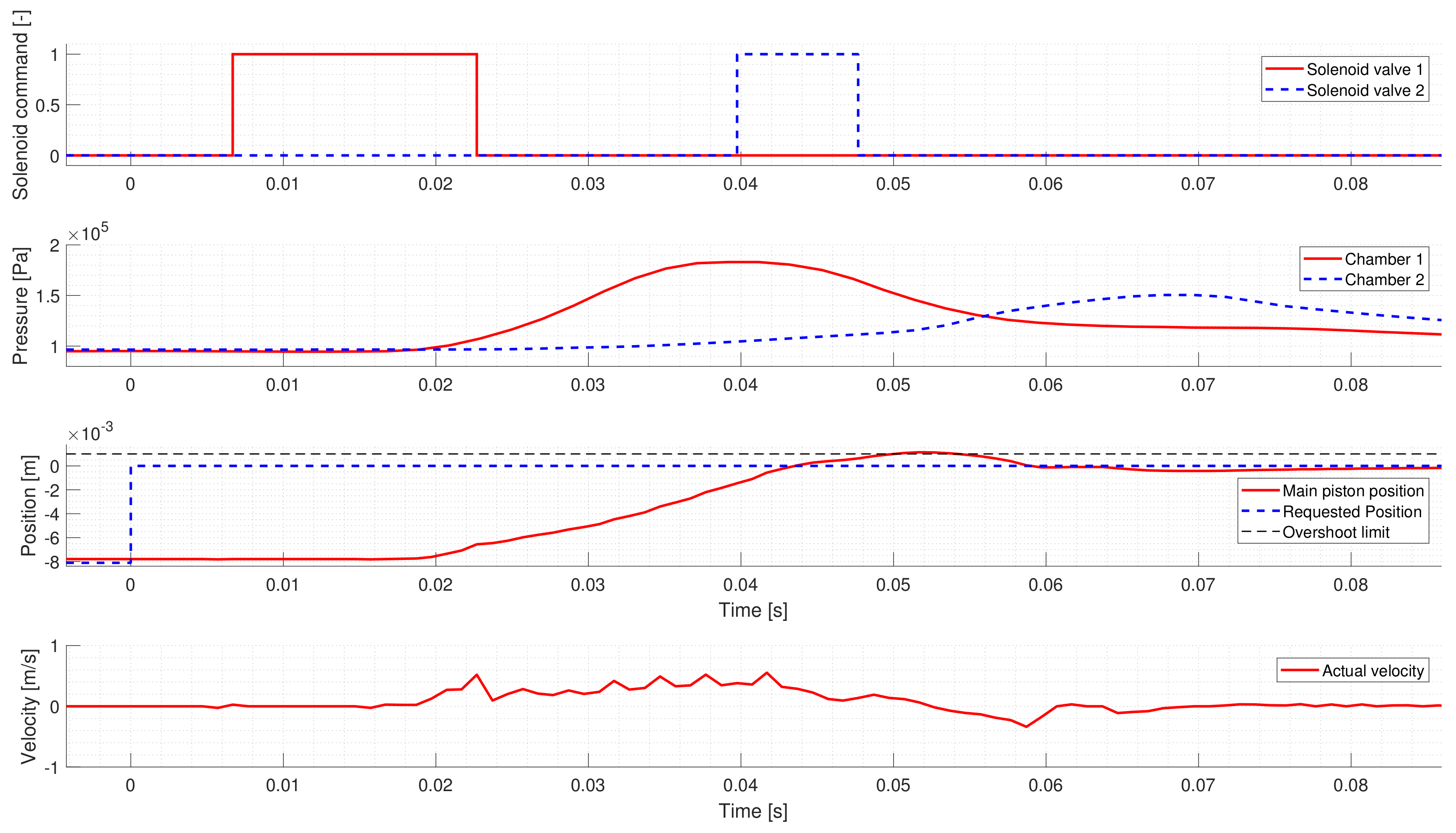
Figure 6 and
Figure 7 present the four gear changes performed by the LPV controller in simulation.
Figure 4 shows a Neutral to High gear change. The first and second diagrams show the solenoid valve commands and the corresponding chamber pressures. The third diagram presents the requested and actual position of the Main Piston, and the fourth diagram shows the Main Piston’s velocity and the maximum allowed collision speed. The controller applies a single solenoid valve command to move the main piston to High. As the valve is activated, the connected chamber’s pressure starts to increase, hence the force generated by the pressure difference moves the pistons towards High. After accelerating the pistons, the solenoid valve is released, thus the chamber pressure starts to decrease. Due to the decreasing pressure difference, the pistons slow down, which guarantees a low-speed collision.
Figure 5 presents a High to Neutral gear change. The diagrams shall be interpreted as
Figure 4, the only difference is that in the case of Gear to Neutral gear shifts, the overshoot limit is presented on the third diagram, while there is no need to include the collision speed limit on the fourth diagram. The controller activates Solenoid valve 2 to shift the gearbox to Neutral, but before the pistons reach Neutral, the controller activates Solenoid Valve 1 to prevent overshoot. At least 5 ms valve commands are required to have a notable effect on the piston’s movement, hence activating Solenoid Valve 1 could be deemed unnecessary, but the control cost must not be further increased. In case of more expensive control, the controller would only intervene to prevent overshoot, when it is too late as it does not consider the delay.
Figure 6 shows a Neutral to Low gear change. Similarly to the first test case, the controller activates the proper solenoid valve to shift the actuator to the requested gear. However, the initial solenoid valve command is too short, and the piston’s movement slows down too early. Hence the controller intervenes and applies a second valve command to ensure that the request is reached. Around 0.278 s, a break-point can be seen in the piston’s velocity, where the piston starts to accelerate, which is not caused by the chamber pressures. The reason for this sudden change is the arrest mechanism, which tries to return the piston to Neutral at the first part of the gear change, but after passing through the break-point, the direction of its force changes, and it tries to move the piston to Low instead.
Figure 7 shows a Low to Neutral gear change, which is very similar to the High to Neutral gear change. The only difference is that the valve command applied to prevent overshoot is longer; hence, it has a minimal effect on the pistons’ movement.
The controller performance is summarized in
Table 1, which shows that the developed controller meets all requirements in simulation.
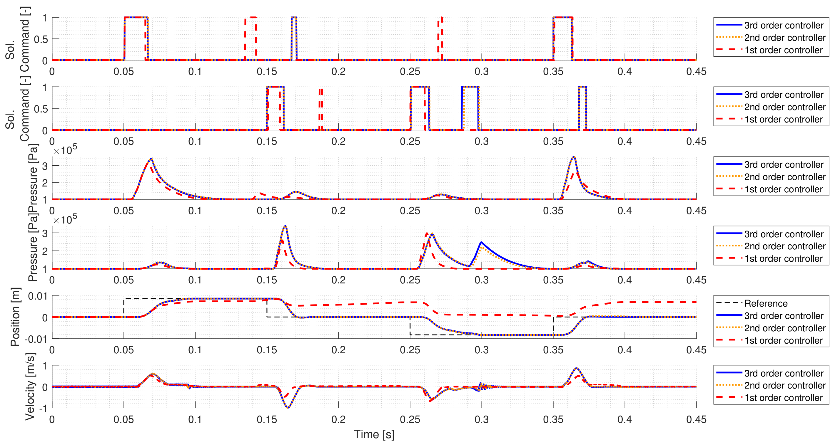
In industrial applications, resource management is an important aspect, as the calculation cost and memory usage of a controller affects the product’s cost. Hence, to find a trade-off between the control’s accuracy and its complexity, simplification possibilities must be considered. To reduce the controller order, a balanced truncation model order reduction has been performed on the controller. The reduced model is obtained by truncating the required number of states, which contribute least to its input-output mapping.
Figure 8 shows the comparison of the original (third-order) controller, and two reduced-order controllers. The second-order controller still has almost identical performance to the original controller, but further decreasing the controller’s order results in significantly worse performance.
6. Conclusions
The paper presents the qLPV representation of an electro-pneumatic gearbox actuator, then shows an LPV controller synthesis using an electro-pneumatic gearbox actuator. The controller is implemented in Matlab/Simulink and tested in a MIL environment and on a gearbox bench using an embedded controller.
First, it is shown, that the pneumatic actuator can be modeled as a quasi-LPV system. Hence a 6th order quasi-LPV model is derived from the nonlinear model of the actuator. To find the control law that stabilizes the system, the qLPV model is simplified to a 2nd order state-space representation. Based on the controlling aims and the system’s characteristics, a generalized plant is formulated, which is used for controller synthesis.
The controller design has two critical points. The computational capacity of an automotive ECU is highly limited. Besides, the maximum six solenoid valve activations per gear shift exclude PWM-based methods, which would be a standard choice to discretize the continuous control signals and to generate the binary control signals of the 3/2 solenoid valves. Therefore, the maximum achievable mass flow rates of the valves are calculated under the actual pressure conditions. If the control signals, which are the required mass flow rates exceed a determined percentage of the maximum value, the valve is energized, otherwise, it is released.
First, the synthesized controller is tested in MIL simulations, but the controller must also be applicable in the given embedded environment. Thus, the controller order is reduced using a balanced truncation model order reduction technique. The reduced model is tested on the gearbox bench, and it is compared with two LTI controllers.
In the case of Neutral to Gear shifts, the LPV controller provides better overall results than the LTI controllers due to the much lower collision speed. During Gear to Neutral gear changes, the gain-scheduled PD controller performs better. Besides, the LPV controller successfully performs these requests, while the LQR controller—which consists of LTI controllers for each linearized model—fails.
Besides, the LPV approach has one advantage over the PD controller. During the design of the gain-scheduled PD controller, the integral term has been eliminated as the system has integration properties. However, if the piston gets stuck in an intermediate error and the solenoid valve is already released, it won’t be activated again. On the other hand, the LPV controller is given in a state-space form, which includes integration, thus if the piston does not reach the request in time, the controller will reactivate the solenoid valve.
