Communication

A Hybrid Electromagnetic and Tendon-Driven Actuator for Minimally Invasive Surgery

Shanghai Institute for Minimally Invasive Therapy, School of Medical Instrument and Food Engineering, University of Shanghai for Science and Technology, Shanghai 200093, China
*
Author to whom correspondence should be addressed.
Actuators 2020, 9(3), 92; https://doi.org/10.3390/act9030092
Submission received: 31 August 2020 / Revised: 16 September 2020 / Accepted: 16 September 2020 / Published: 21 September 2020
(This article belongs to the Special Issue Smart Actuators for Endoscopic Robots)

Abstract

:
Minimally invasive surgery (MIS) is a surgical technique that facilitates access to the internal tissues and organs of a patient’s body via a limited number of small incisions or natural orifice of the patients. Such a technique requires specialized slender surgical instruments with a high levels of dexterity and functionality. However, the currently available MIS instruments are rigid and could offer only limited degrees of freedom (DOFs) that hampers the surgeon’s effort to perform the required operation accurately. In this study, we have developed a hybrid electromagnetic and tendon-driven actuator as an integral part of MIS surgical instruments to provide them with optimum angulation. The design uses a novel electromagnetic structure to lock the position of individual joints, and a tendon-driven structure for the articulation of the surgical instrument. The finite element method (FEM) was utilized to predict the performance of the actuator, which was experimentally validated. Subsequently, a prototype was assembled, and corresponding kinematics analysis was presented to visualize the improvement of the developed mechanism on the functional workspace of the MIS instruments. It was concluded that the developed mechanism could offer three additional DOFs for the surgical instrument and angulation of 180° for each articulated joint.

1. Introduction

Owing to the small size of the incisions, minimally invasive surgery (MIS) has many advantages, such as reduced trauma, less risk of wound infections, minimal postoperative pain, shorter hospitalization stay, and earlier return-to-normal activities, over traditional open surgery [1,2]. Therefore, MIS has become increasingly popular and accepted by the general public in recent years. However, confined surgical space and limited flexibility of the surgical tools lead to the lack of instrument triangulation, an inherent problem of all MIS techniques, which renders certain MIS tasks very difficult and time-consuming [3,4].
Many articulated actuators, such as tendon-driven actuators, have been developed to solve this problem and enhance the dexterity of the MIS instruments [5]. These actuators have been widely adopted in various surgical systems, including the Da Vinci surgical robot [6]. Similar to human muscles, the tendon-driven actuator requires a pair of wires to control each degree of freedom (DOF). To achieve an MIS instrument with multiple DOFs, the actuation of multiple flexible joints should be transmitted from external units via multiple tendons routed in flexible sheaths or around pulleys to avoid wire friction and tangling. Such arrangements would notably occupy the internal and external space of the MIS instrument and hamper their further miniaturization [7]. The complex routing of the tendons could also result in poor force delivery capability, which is due to the inherent tendon friction issues as well as control problems resulting from backlash hysteresis of the system [8]. In addition, high pretension of the tendons and corresponding excessive pulling force are also required to maintain the angulation of the tendon-driven actuator, hence result in a bulky and large size of the surgical system [9].
To enhance the dexterity of the MIS instruments while avoiding the aforementioned drawbacks of ordinary tendon-driven actuators, many novel actuators have been developed. Minor et al. [10] utilized a gear mechanism for the articulation of MIS manipulators, which could provide two additional DOFs with bi-directional angulation of 180°. Giataganas et al. [11] has developed an Shape Memory alloy (SMA)-wires based tendon-driven configuration for endoscopic surgical tools, where each actuator could achieve a two-DOF articulation (40°) with a length of 50.5 mm. Other means of actuation for MIS devices, such as the pneumatic actuator [12] developed by Cianchetti et al., could offer a maximum angulation of 120° within a length of 50 mm, while the diameter of this actuator reaches 35 mm. Even though these actuators could offer better dexterity for MIS instruments compared to the conventional tendon-driven actuator, they are also more likely to suffer from problems such as size limitation, control hysteresis, and bulky power unit [10,11,12].
In this study, we have proposed a hybrid electromagnetic and tendon-driven actuator as an integral part of an MIS surgical instrument to achieve optimum angulation. The design has used a tendon-driven structure to actuate the individual joints and an electromagnetic structure to lock the shape of the actuator. Prototypes of the proposed actuator are manufactured. Subsequently, the forward kinematics analysis of the developed system is carried out, and the performance of the new actuator is evaluated numerically and experimentally.

2. Materials and Methods

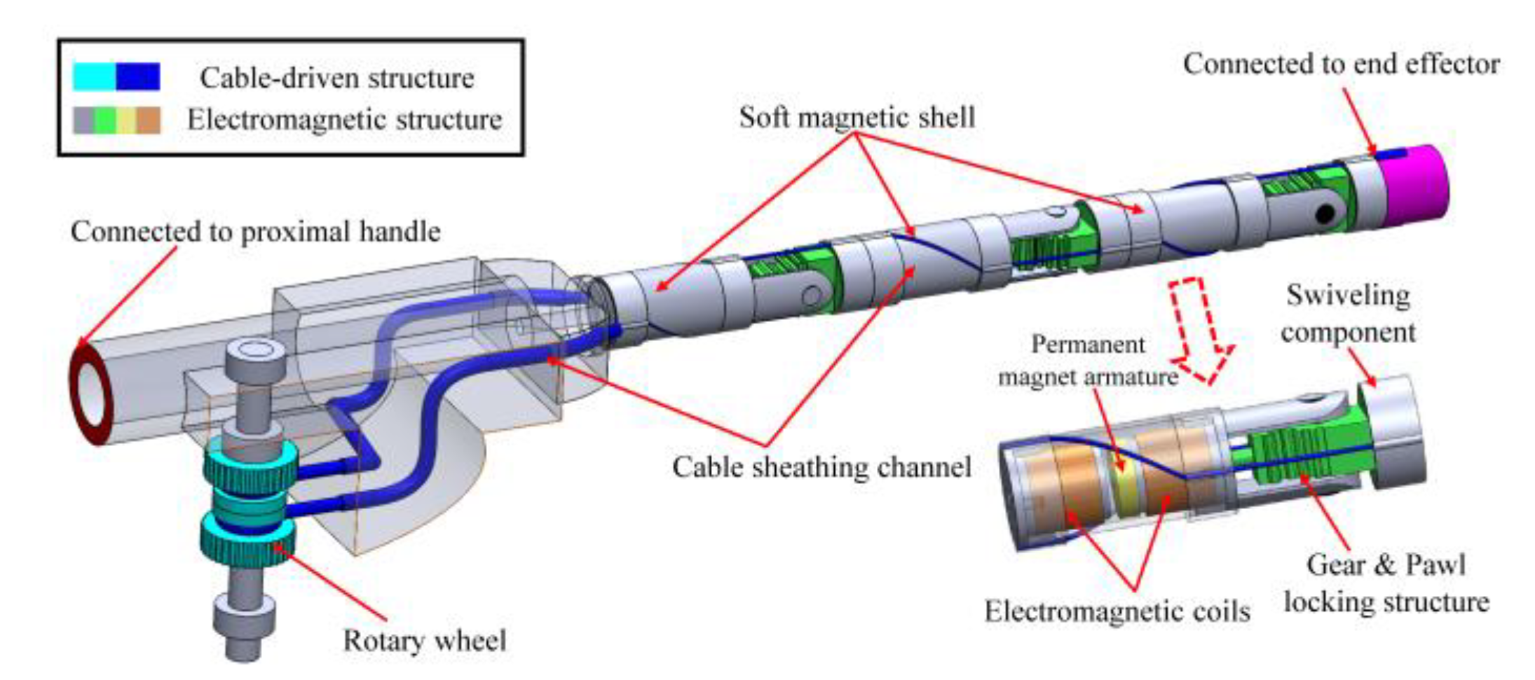
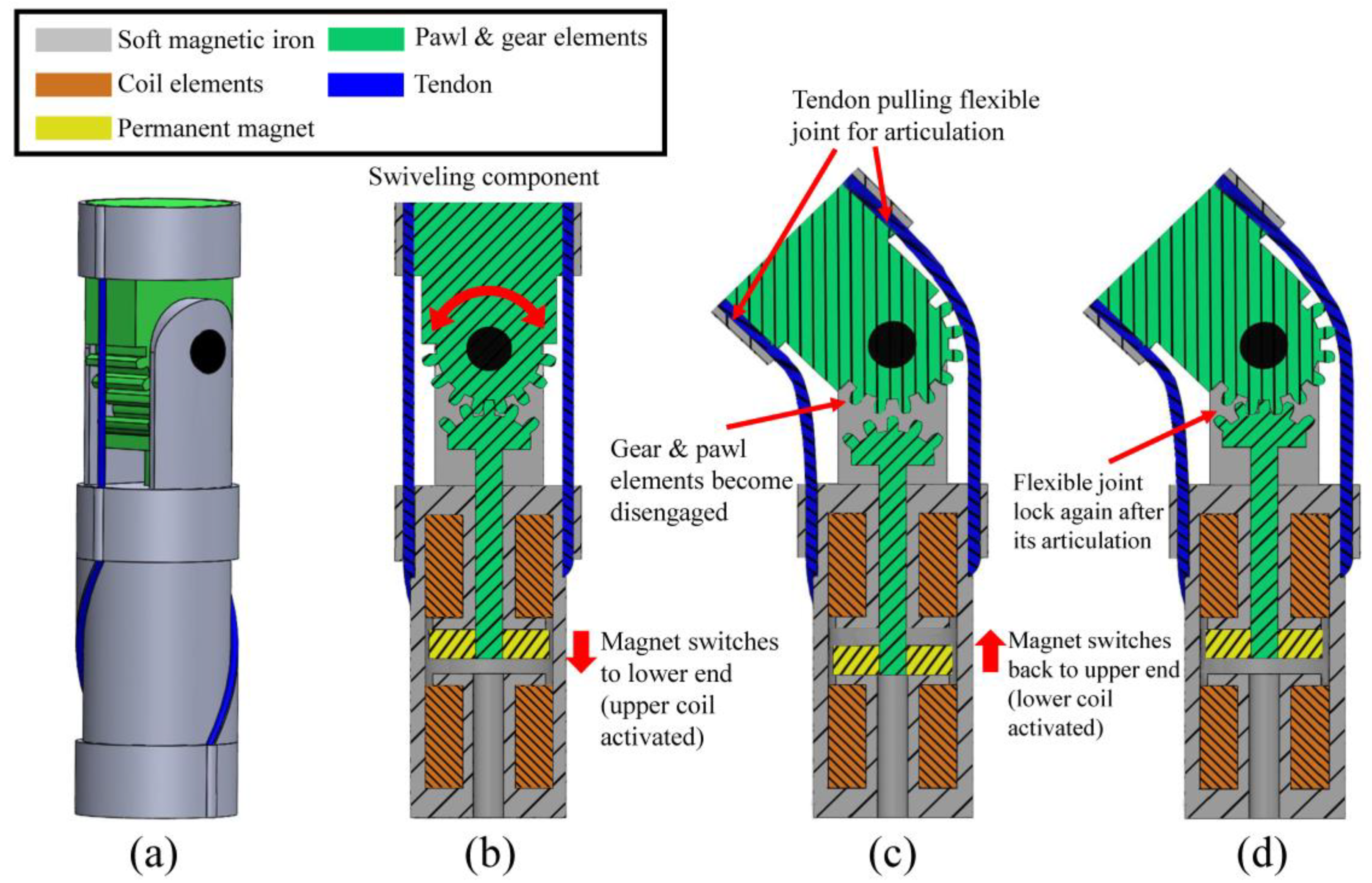
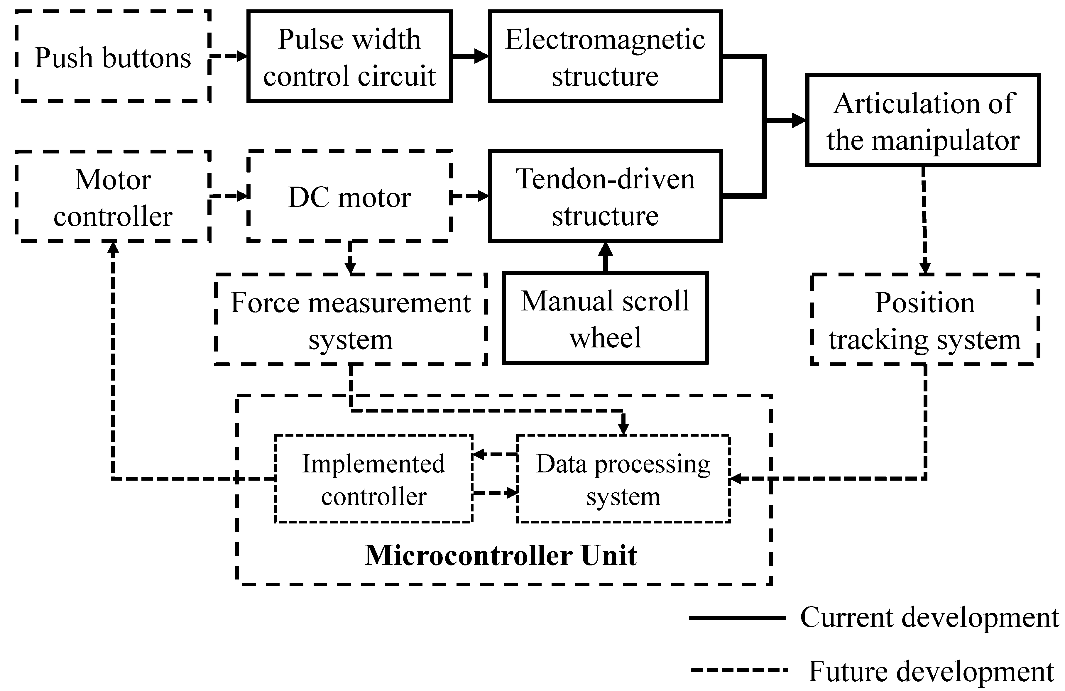
2.1. Design of the Hybrid Electromagnetic and Tendon-Driven Actuator for MIS

The locking mechanism has long been an effective solution for the position control of robotic applications. An optimum locking structure could achieve the reconfiguration of flexible joints with compact size, fast response, and low energy consumption [13]. Therefore in this study, the new actuator comprises an electromagnetic structure as a locking mechanism and a tendon-driven structure for angulation (as shown in Figure 1). The tendon-driven structure was designed to manually actuate the swiveling component to a desired angulation and electromagnetic structure was proposed to lock (hold) its position. In particular, two scroll wheels located at the proximal end of the surgical instrument handle were used to control the two tendons that are connected to the distal end effector of the tool. When one of the wheels is rolled, its associated tendon is pulled against the sheathing channel, causing the swiveling component to turn.
The alignment of the joints could be adjusted based on the requirements of the MIS instruments. We presented an example in which each of the tendons passes through a sheathing channel located at 90° from the hinge of the swiveling component, which gives the MIS instrument an additional three DOFs movement in different directions.
The swiveling component of the actuator was designed as a spur gear structure, with its lower pawl gear component connected to the permanent magnet, as shown in Figure 2. The novel electromagnetic structure utilizes the magnetic force established between the permanent magnet and the soft magnetic ends of the central chamber to maintain the position of the armature during the deactivated status of the actuator (with no power consumption). The two coils located at either end of the central chamber were used to generate a short pulse of repelling magnetic force, which drives the armature sliding between the two ends.
When the permanent magnet is attached to the upper end of the sliding chamber, the pawl gear engages itself into the upper gear element and hence locks the movement of the top swiveling component. Since the pawl element is horizontally aligned with the gear structure, practically, the braking torque generated by the swiveling component would exert forces only on the pawl element along the horizontal direction. Hence, it should not affect the vertical position of the linked permanent magnet armature.
In contrast, when the magnet switches its position to the lower end of the central chamber after the activation of the corresponding coil element, the gear and pawl elements become disengaged, and the rotation of the swiveling joint could be proceeded again by the tendon-driven structure. Accordingly, the actuator could be transformed from a solid state to a flexible state and vice versa, based on the instrument’s articulated shape requirement.
Compared to the ordinary tendon-driven actuator, the tendons used in this design do not need to be in tension during the surgical procedure to maintain the desired angulation of individual joints, and hence the required shape of the tool. Because the stiffness of each actuator could be set individually, only one pair of tendons was required to control the bending of all the flexible joints, which significantly reduces the overall space requirement for the tendon-driven structure. The proposed electromagnetic structure was previously developed and optimized by the author for MIS applications [14]. However, unlike the previous design that could only provide an angulation of 30°, the hybrid actuator could offer an angulation from −90° to 90° with a step angle of 22.5° (the spur gear structure has eight teeth in 180°) for each joint, while the achievable positions of the joint could be further increased with the intensification on the number of gear teeth. The developed actuator was manufactured using a conventional computerized numerical control (CNC) machining facility, and its parameters are summarized in Table 1.

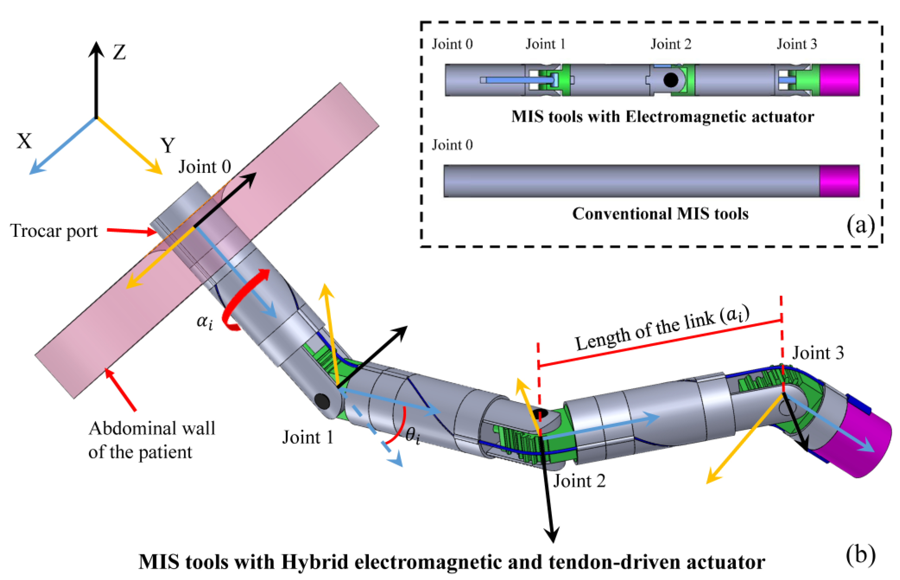
2.2. Kinematic Analysis of the Hybrid Electromagnetic and Tendon-Driven Actuator

To visualize the functional workspace of the developed hybrid electromagnetic and tendon-driven actuator whilst compare it with the conventional MIS instruments and previous design [14], MATLAB software (MathWorks, Inc. Natick, Massachusetts, USA) was utilized to produce forward kinematics of these systems in this study.
The kinematic models of the surgical instruments are first simplified to joints (points), which can rotate around the X- and Z-axis, and links (lines) connecting these joints. Figure 3 shows the articulated systems where each joint is identified as the rotation center of the swiveling component. In contrast, the conventional surgical instrument does not offer any flexibility (angulation) along its length, and hence the whole shaft of this tool was assumed as a straight line in the current kinematic analysis. The individual movements of each link and joint were then identified and exported into the MATLAB software, which was used to plot the reachable points of the end effector for each assessed surgical system.
Denavit–Hartenberg convection method [16] was adopted to evaluate the position of the end effector of the surgical instruments in the global coordinate system. Assume that when an MIS tool is inserted into the abdominal cavity of the patient through a trocar port, the insertion point is located at coordinates X = 0, Y = 0, and Z = 0, where the X-axis spans the direction of the tool’s insertion and Z-axis and Y-axis are normal to it. The usual penetration depth of MIS tools inside the patients’ abdominal cavity is around 150 mm [17], and the working space of ordinary MIS tools is expected to be in a vertex cone with a top angle of 60° [18]. Therefore, the depth of the permissible movement of the MIS was determined to be 160 mm and the rotation angle θ0 at the insertion point is –30° to 30°. Also, the MIS tools could be twisted 360° around the insertion point during most of the operation [17,18].
The permissible movements of the conventional MIS instruments, electromagnetic actuator, and the developed hybrid actuator are presented in Table 2 for D-H matrix modeling, where αi is the rotational angle of each joint around the X-axis, ai is the length between the current joint and the next joint along X-axis, di is the length of offset along Z-axis which is zero in all cases, and θi is the angulation of each joint around Z-axis.
Accordingly, the coordinates transformation matrix of individual joints could be expressed as:
T i N = [ c o s θ i s i n θ i c o s α i s i n θ i s i n α i a i c o s θ i s i n θ i c o s θ i c o s α i c o s θ i c o s α i a i s i n θ i 0 s i n α i c o s α i d i 0 0 0 1 ]
In the clinical operation, the surgical tools could be gradually inserted into the patient’s abdominal cavity through the trocar port, which gives the final transformation matrix of each system below:
T E 1 = T 0 1 T 0 1 T 3 1 T 0 1 T 2 1 T 3 1 T 0 1 T 0 1 T 1 1 T 2 1 T 3 1
T E 2 = T 0 2 T 0 2 T 3 2 T 0 2 T 2 2 T 3 2 T 0 2 T 0 1 T 1 2 T 2 2 T 3 2
T E 3 = T 0 3
where T E 1 , T E 2 , and T E 3 were the transformation matrix of the end effector for surgical systems 1, 2, and 3, respectively. Finally, the coordinates of the end effector of the three systems in the global coordinate system could be derived from the above matrix as:
X E N = T E N ( 1 ,   4 ) ;   Y E N = ( 2 ,   4 ) ; Z E N = T E N   ( 3 ,   4 )
In particular, when θ0 was fixed to be 0°, the surgical devices are allowed to be inserted only as straight tools through the trocar ports, without subjecting them to any tilting about the entrance of the insertion, which is ideal for the MIS with less flexibility such as natural orifice transluminal endoscopic surgery (NOTES) and single-incision laparoscopic surgery (SILS).

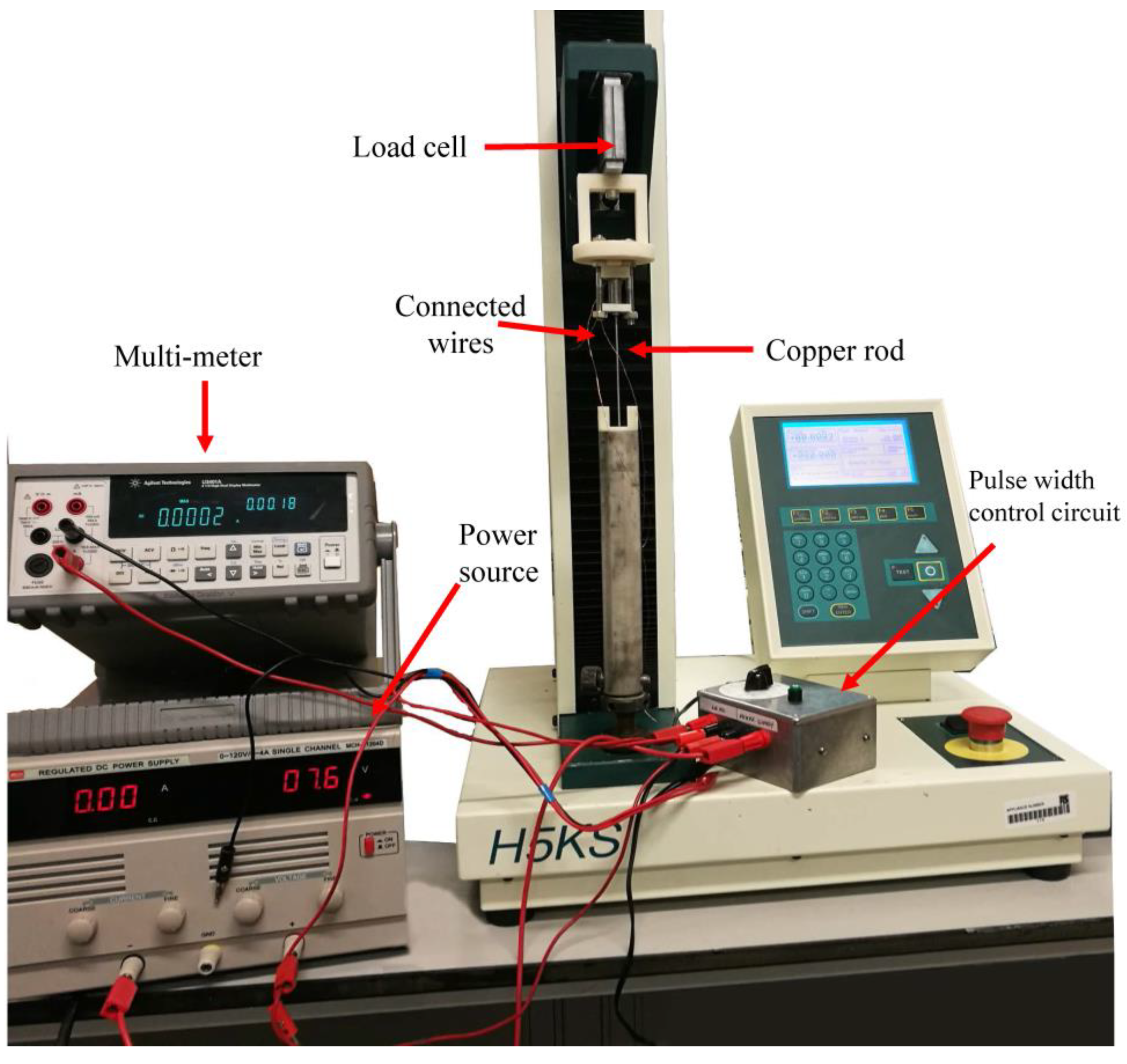
2.3. Numerical and Experimental Evaluation of the Actuator Performance

Figure 4a shows the novel developed actuator that provides various angulations (−90° to 90°), which was compared to the previous design [14] that could only offer a single angulation of 30°. Since the permanent magnet no longer needed to provide the actuation movements for the articulation, the structure of the actuators was slightly changed, where the slot and side link on the soft magnetic shell was dismissed. Accordingly, numerical and experimental approaches were utilized to evaluate the performance of the developed hybrid actuator.
Finite element methods (FEM) are utilized to predict the force output of the actuator, which were carried out using Ansys Maxwell 19 software (ANSYS, Inc. Canonsburg, PA, USA), as shown in Figure 4b. The 3-D model of a single actuator was created using SolidWorks CAD software (Dassault Systemes, Inc. Waltham, MA, USA) and subsequently exported into Ansys Workbench environment. To estimate the locking force of the actuator, the permanent magnet armature was assumed to travel statically along its stroke in both activated and deactivated statuses, while the corresponding magnetic forces acting on the permanent magnet armature were recorded. The detailed parameters of the simulation are summarized in Table 3.
Experimentally, a Tinius Olsen H5KS Force Tester (Tinius Olsen Ltd. Redhill, UK) with a load of 10 N was employed to measure the magnetic force along the stroke of the actuator, as shown in Figure 5. The shell of the actuator was vertically aligned and fixed to the load cell of the tensile machine using a screw clamping actuator. In contrast, the upper gear component of the actuator was removed, and the lower pawl component was bonded to the base of the tensile machine through a copper rod. In such arrangements, the input axial displacements of the pawl component were provided by the tensile machine, and the corresponding magnetic forces were recorded by the load cell when the actuator was deactivated. In addition, a special circuit was developed to energize the electromagnetic coil element of the actuator with a current of 6.7 A and with a pulse length of 0.1 s, where the peak forces during the activation of the actuator were recorded as the magnetic force at each position.

3. Results and Discussion

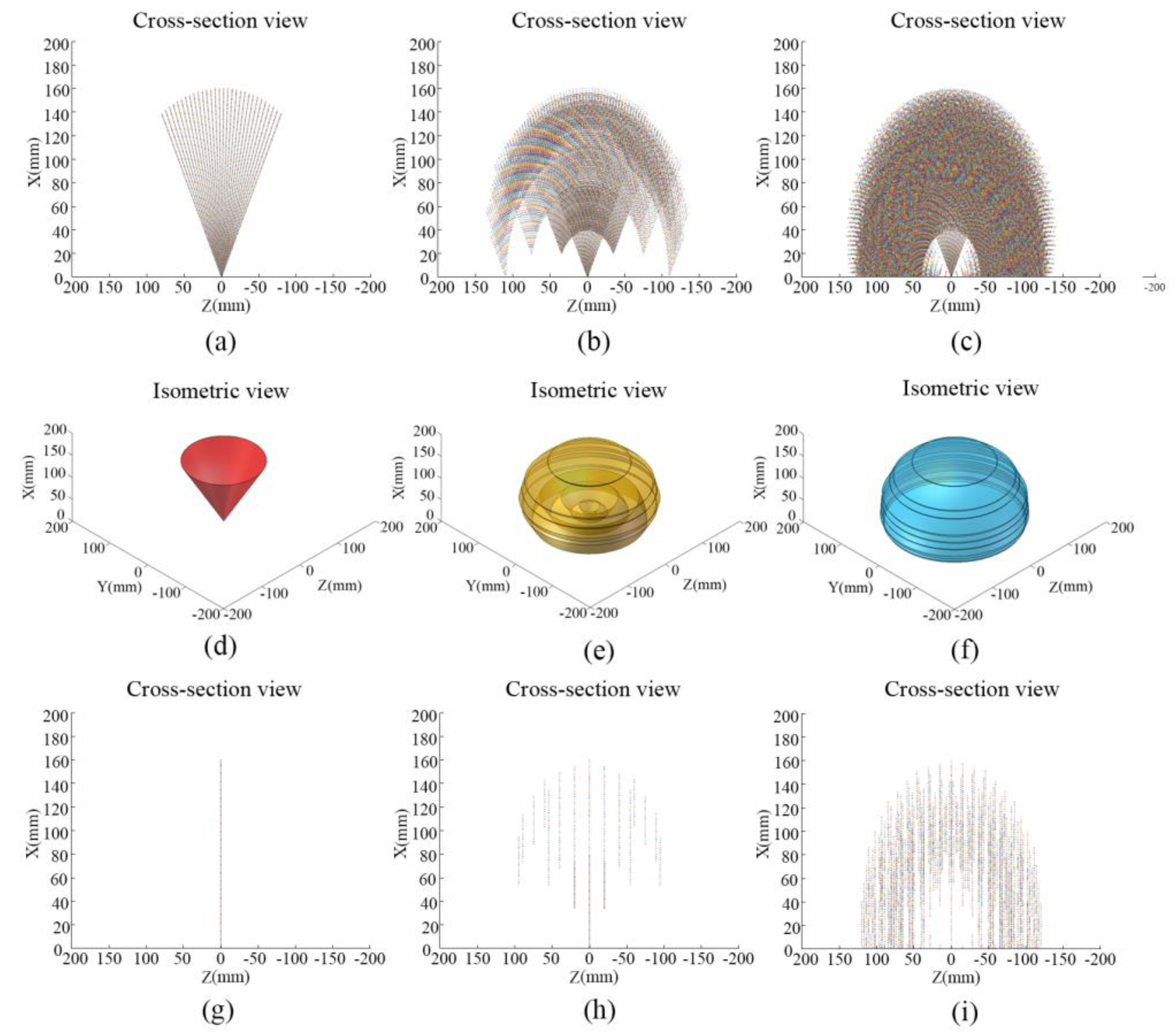
3.1. Workspace of the Developed Hybrid Electromagnetic and Tendon-Driven Actuator

Figure 6a–c displays the reachable points of the end effector for each assessed surgical system in a cross-section view (the plot was inverted for ease of observation, where the MIS tool was assumed to be inserted from bottom to top). Since the roll angle at the insertion point is 360° for all systems, the corresponding isometric functional workspace of the three systems could then be derived from the cross-sectional plot, as shown in Figure 6d–f.
It is clear that the addition of the proposed articulated actuator to conventional MIS instruments could significantly enhance their functional workspace. The functional space of the ordinary MIS tools was 1149.32 cm3, while the functional space of the articulated MIS tools with the electromagnetic actuator and hybrid actuator was 6335.32 cm3 and 7009.82 cm3 respectively. Furthermore, in MIS with less flexibility such as SILS and NOTES, where the tilting of the MIS tools about the entrance of the insertion was restrained to zero degrees as presented in Figure 6g–i, the developed novel actuator could still provide an adequate functional workspace for the MIS procedure, while the flexibility of the other two systems is limited.

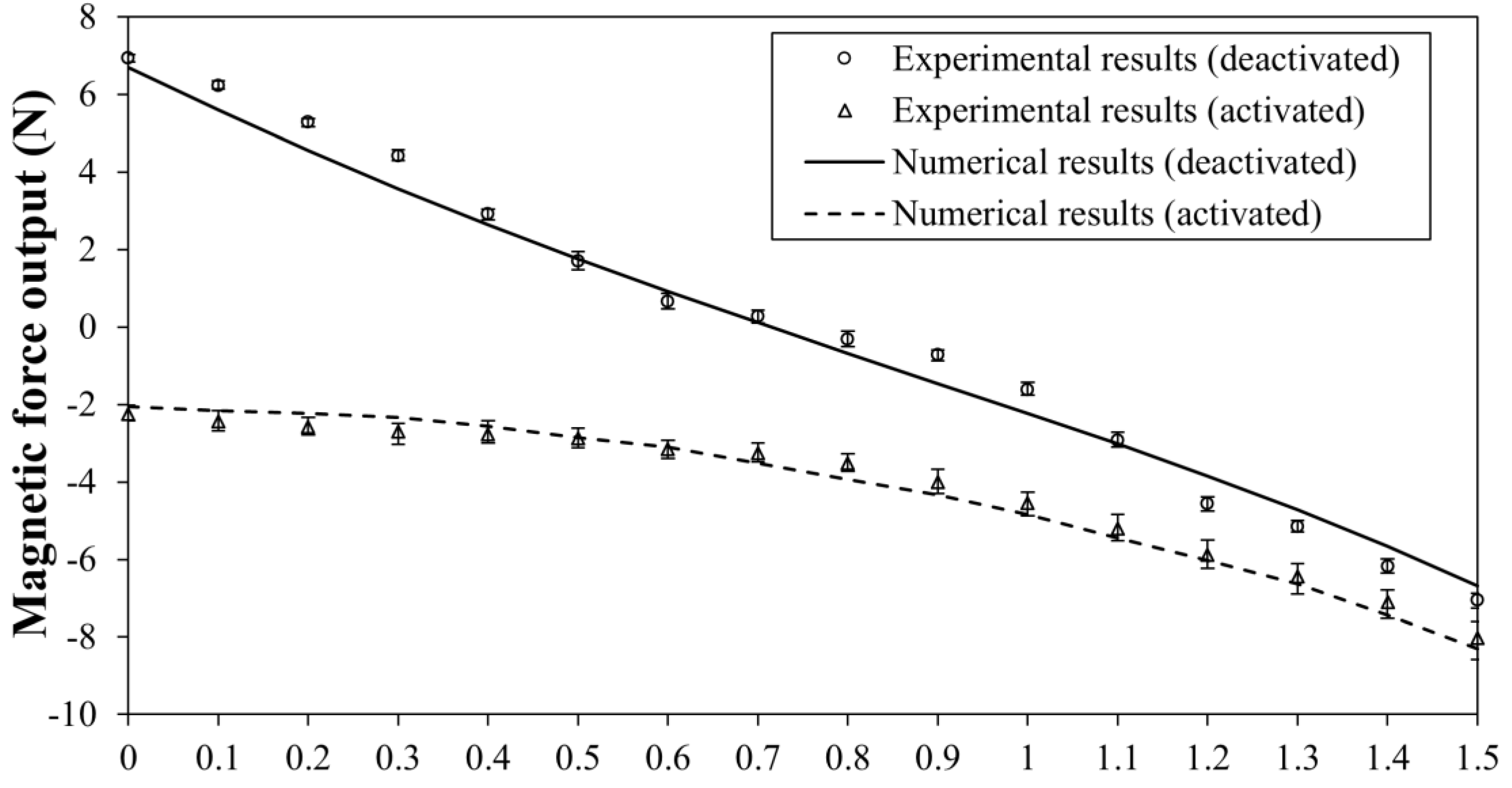
3.2. Force Output of the Electromagnetic Structure

Figure 7 shows the results of the magnetic force tests, presenting the force output of the actuator in both activated and deactivated statuses. We conducted five trials for each position to validate the repeatability of the experiments. As shown in Figure 7, the actuator could exert a force in excess of 7 N in its locking status (deactivated status), whereas a magnetic force of about 2.25 N could be obtained during the initiation of the pawl component’s movement (activated status).
In comparison with other shape-locking investigations, such as Li et al. [19] achieved a maximum force output of 8 N for soft robotic grippers and Brancadoro et al. [20] achieved a maximum force output of 0.88 N for the MIS manipulator, the force output of this new actuator was considered to be adequate for maintaining the shape of the articulated MIS instruments.
In addition, it could also be observed that the deactivated data have relatively smaller errors when compared to the activated data. The reason is that when the coil is deactivated, the magnetic field interaction is established only between the permanent magnet armature and the soft magnetic material. However, when the coil is activated with current supply, there could be some magnetic noise generated in addition to the main magnetic field, which increased the possible errors in the obtained results. Nevertheless, the standard deviations in both tests are below a maximum value of 0.46 N, which indicates good repeatability of the results.

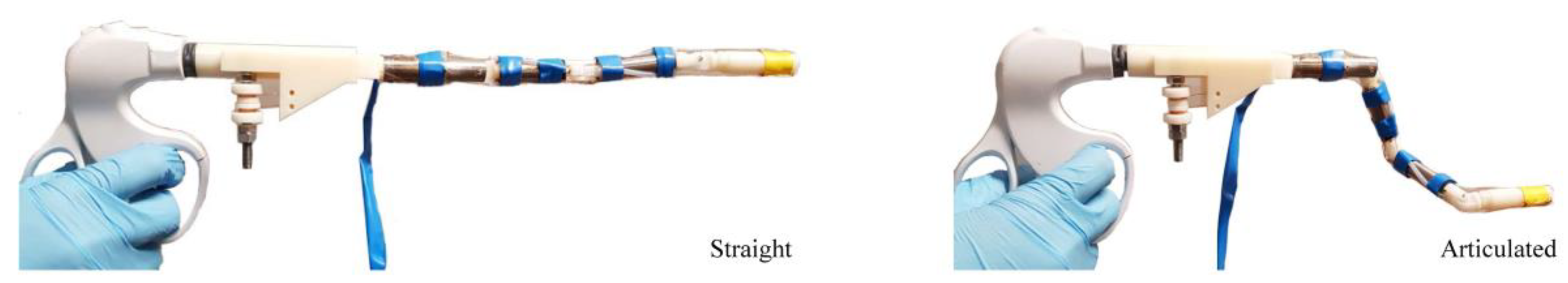
3.3. Prototype of the Developed Actuator

Figure 8 shows a prototype of the proposed actuator manufactured using a conventional computer numerical control machining facility. Minor slackness was observed with the spur gear actuator, which is ascribed mainly to the precision of the 3D plastic printer used to manufacture the spur gear components. This difficulty could be eliminated using customized stronger and more precise metallic components instead of the current present plastic parts. A rotary switch in conjunction with a push button was employed to control the actuation of different actuators. Since the actuation of the articulated joints was provided by the manual scroll wheel through only one pair of wires, the surgeon could have directly haptic sensing during the articulation of the instrument, which is considered to be ergonomic and safe.
The developed actuator could potentially provide three additional DOFs with 180° angulations for surgical instruments. In particular, the high dexterity of such design is well suited for devices in single-incision laparoscopic surgery (SILS), where only a single entry instead of multiple incisions is utilized to accommodate all the surgical instruments for their access to the patient’s abdominal cavity. Technical challenges of current SILS induced by the lack of instrument flexibility, such as clashing of the external handles [21], the fulcrum effect [22], and parallel alignment of instruments [23] could be alleviated with the addition of the proposed design. Furthermore, the shape of the proposed instruments will be locked after the adjustment, which enable the device to be manipulated by a single hand of the surgeon. The performance of the developed actuator was summarized in Table 4, which is benchmarked against other actuators (developed for SILS) already reported in the literature [12,14,24].
Even though the proposed hybrid electromagnetic and tendon-driven actuator could enhance the dexterity of the MIS instrument to a great extent, it has few drawbacks as well. Since the central channel of the actuator was occupied by the gear element in this design, the tendon to control the end effector is required to be routed through a sheath constructed beneath the outer surface of the MIS instrument, which would increase the overall diameter of the device by 1 mm.
In addition, since the gear structure discretizes the achievable positions of the joint, the obstruction of the swiveling component could fail when the pawl does not engage the gear structure at certain positions. However, such circumstances were rarely observed during the experimental trails since the dedendum of the gear structure is 0.5 mm and the stroke of the permanent magnet armature is 1.5 mm in this design. As long as the pawl could slide into one of the gaps between the gear tooth, the pawl structure would be subjected to at least a magnetic force of approximately 1.6 N that drives it towards the other ends, even without the activation of the coils (as shown in Figure 7, deactivated status). Accidentally, if the engagement of the pawl and gear structure fails, the pawl component would back to its original position (lower end), which would not affect the functionality of the actuator and further reconfiguration of the joint.
Currently, the articulation of the developed prototype was controlled by pulling the corresponding tendon wire through the manual scroll wheel, which causes mechanical backlash and is lack of control accuracy. In addition, the lock and release status of each joint is controlled separately, and such design may not be favored by the surgeons as it may increase the complexity of the surgical operation. To solve these problems, a lightweight electric motor could be integrated on the proximal handle of the proposed instruments to actuate the wires and hence control the movement of the instrument. The actuator should be compact which could fit in the proximal handles of current MIS tools, while be capable of generating a torque output at least 14 N.mm [9]. The ideal actuator should offer high power density, high torque at low speed and precise motion [9]. Force sensor and position tracking system would be introduced for further evaluation of the accuracy and output capability of the developed actuator. Push buttons could be arranged near the thumb of the surgeon to control the locking and releasing of the individual embedded electromagnetic actuators and pulling of the tendons. A corresponding block diagram of the proposed system was presented, as shown in Figure 9. However, this investigation is a preliminary study that mainly focused on the design of the new actuator, while the aforementioned system would be developed and assessed completely through further study.

4. Conclusions

In this study, we introduced a novel hybrid electromagnetic and tendon-driven actuator. The proposed actuator was designed as an integral part along the stem of the MIS instruments and could provide three additional DOFs with angulation between −90° and 90°. We manufactured the prototypes of the developed actuator and also evaluated the performance of the actuator through numerical and experimental approaches. The workspace of the developed system is presented, and it was found that the dexterity of the MIS tools was improved significantly with the addition of the proposed design.

Author Contributions

Conceptualization, H.W.; methodology, H.W. and C.S.; software, H.W., S.C. and Y.W.; validation, H.W. and C.S.; formal analysis, H.W.; investigation, H.W.; resources, H.W. and C.S.; writing—original draft preparation, H.W.; writing—review and editing, H.W., S.C., Y.W. and C.S.; supervision, C.S.; project administration, H.W. and C.S.; funding acquisition, H.W. and C.S. All authors have read and agreed to the published version of the manuscript.

Funding

This work was supported by the National Natural Science Foundation of China (No.51735003), Shanghai Science and Technology Commission (No. 18441900200), and China Postdoctoral Science Foundation Grant (No.2019TQ0203), PR China.

Conflicts of Interest

The authors declare no conflict of interest.

References

  1. Jaffray, B. Minimally invasive surgery. Arch. Dis. Child. 2005, 90, 537–542. [Google Scholar] [CrossRef] [PubMed] [Green Version]
  2. Peter, S.D.S.; Holcomb, G.W., III. History of minimally invasive surgery. In Atlas of Pediatric Laparoscopy and Thoracoscopy; Saunders: Lodon, UK, 2008. [Google Scholar]
  3. Alevizos, L.; Brinkman, W.; Fingerhut, A.; Jakimowicz, J.; Leandros, E. Novice Surgeons Versus Experienced Surgeons in Laparoendoscopic Single-Site (LESS) Surgery: A Comparison of Performances in a Surgical Simulator. World J. Surg. 2012, 36, 939–944. [Google Scholar] [CrossRef] [PubMed]
  4. Lee, S.-H. Single port laparoscopic surgery: Mission completed or more evolution to come? Ann. Laparosc. Endosc. Surg. 2017, 2, 79. [Google Scholar] [CrossRef]
  5. Li, Z.; Wu, L.; Ren, H.; Yu, H. Kinematic comparison of surgical tendon-driven manipulators and concentric tube manipulators. Mech. Mach. Theory 2017, 107, 148–165. [Google Scholar] [CrossRef]
  6. Anderson, P.L.; Lathrop, R.; Herrell, S.D.; Webster, R.J. Comparing a Mechanical Analogue with the Da Vinci User Interface: Suturing at Challenging Angles. IEEE Robot. Autom. Lett. 2016, 1, 1060–1065. [Google Scholar] [CrossRef] [PubMed]
  7. Simaan, N.; Yasin, R.M.; Wang, L. Medical technologies and challenges of robot-assisted minimally invasive intervention and diagnostics. Annu. Rev. Control Robot. Auton. Syst. 2018, 1, 465–490. [Google Scholar] [CrossRef] [Green Version]
  8. Do, T.N.; Tjahjowidodo, T.; Lau, M.W.S.; Phee, S.J. Adaptive Control of Position Compensation for Cable-Conduit Mechanisms Used in Flexible Surgical Robots. In Proceedings of the 11th International Conference on Informatics in Control, Campeche, Mexico, 29 September–3 October 2014; pp. 110–117. [Google Scholar]
  9. Le, H.M.; Do, T.N.; Phee, S.J. A survey on actuators-driven surgical robots. Sens. Actuators A Phys. 2016, 247, 323–354. [Google Scholar] [CrossRef]
  10. Minor, M.; Mukherjee, R. A dexterous manipulator for minimally invasive surgery. In Proceedings of the 1999 IEEE International Conference on Robotics and Automation, Detroit, MI, USA, 10–15 May 1999. [Google Scholar]
  11. Giataganas, P.; Evangeliou, N.; Koveos, Y.; Kelasidi, E.; Tzes, A. Design and experimental evaluation of an innovative SMA-based tendon-driven redundant endoscopic robotic surgical tool. In Proceedings of the 19th Mediterranean Conference on Control & Automation (MED), Corfu, Greece, 20–23 June 2011; pp. 1071–1075. [Google Scholar]
  12. Cianchetti, M.; Ranzani, T.; Gerboni, G.; De Falco, I.; Laschi, C.; Menciassi, A.; De Falco, I. STIFF-FLOP surgical manipulator: Mechanical design and experimental characterization of the single module. In Proceedings of the 2013 IEEE/RSJ International Conference on Intelligent Robots and Systems, Tokyo, Japan, 3–7 November 2013; pp. 3576–3581. [Google Scholar]
  13. Plooij, M.; Mathijssen, G.; Cherelle, P.; Lefeber, D.; VanderBorght, B. Lock Your Robot: A Review of Locking Devices in Robotics. IEEE Robot. Autom. Mag. 2015, 22, 106–117. [Google Scholar] [CrossRef]
  14. Wang, H.; El Wahed, A.K. Development of a Novel Latching-Type Electromagnetic Actuator for Applications in Minimally Invasive Surgery. Actuators 2020, 9, 41. [Google Scholar] [CrossRef]
  15. Tennant Metallurgical Group Ltd. Chesterfield, United Kingdom. Electromagnetic Test on Cast 80626. Available online: http://www.tenmet.co.uk/ (accessed on 18 April 2020).
  16. Hartenberg, R.S.; Denavit, J. A kinematic notation for lower pair mechanisms based on matrices. J. Appl. Mech. 1955, 77, 215–221. [Google Scholar]
  17. Soper, N.J.; Swanström, L.L.; Eubanks, S. (Eds.) Mastery of Endoscopic and Laparoscopic Surgery; Lippincott Williams & Wilkins: Philadelphia, PA, USA, 2008. [Google Scholar]
  18. Lum, M.J.H.; Rosén, J.; Sinanan, M.N.; Hannaford, B. Kinematic optimization of a spherical mechanism for a minimally invasive surgical robot. In Proceedings of the IEEE International Conference on Robotics and Automation, New Orleans, LA, USA, 26 April–1 May 2004; Volume 1, pp. 829–834. [Google Scholar]
  19. Li, Y.; Chen, Y.; Yang, Y.; Wei, Y. Passive Particle Jamming and Its Stiffening of Soft Robotic Grippers. IEEE Trans. Robot. 2017, 33, 446–455. [Google Scholar] [CrossRef]
  20. Brancadoro, M.; Manti, M.; Grani, F.; Tognarelli, S.; Menciassi, A.; Cianchetti, M. Toward a Variable Stiffness Surgical Manipulator Based on Fiber Jamming Transition. Front. Robot. AI 2019, 6, 12. [Google Scholar] [CrossRef] [Green Version]
  21. Chern, B.S.M.; Lakhotia, S.; Khoo, C.K.; Siow, A.Y.M. Single incision laparoscopic surgery in gynecology: Evolution, current trends, and future perspectives. Gynecol. Minim. Invasive Ther. 2012, 1, 9–18. [Google Scholar] [CrossRef] [Green Version]
  22. Romanelli, J.R.; Earle, D.B. Single-port laparoscopic surgery: An overview. Surg. Endosc. 2009, 23, 1419–1427. [Google Scholar] [CrossRef] [PubMed]
  23. Allemann, P.; Leroy, J.; Asakuma, M.; Al Abeidi, F.; Dallemagne, B.; Marescaux, J. Robotics May Overcome Technical Limitations of Single-Trocar Surgery. Arch. Surg. 2010, 145, 267–271. [Google Scholar] [CrossRef] [PubMed] [Green Version]
  24. Shang, J.; Noonan, D.; Payne, C.; Clark, J.; Sodergren, M.; Darzi, A.; Yang, G.-Z. An articulated universal joint based flexible access robot for minimally invasive surgery. In Proceedings of the 2011 IEEE International Conference on Robotics and Automation, Shanghai, China, 9–13 May 2011; pp. 1147–1152. [Google Scholar]
Figure 1. Design of the hybrid electromagnetic and tendon-driven actuator.
Actuators 09 00092 g001
Figure 2. Working principle of the electromagnetic structure. (a) Isometric view of one actuator. (b) Cross-sectional view of the actuator in the locking position. (c) The gear and pawl elements become disengaged, while the swiveling joint rotates by the tendon-driven structure. (d) The swiveling joint locks again after the desired angulation achieved.
Actuators 09 00092 g002
Figure 3. Links and joints of the MIS tools for kinematic analysis. (a) Conventional MIS tools and MIS tools with the electromagnetic actuator. (b) MIS tools with hybrid electromagnetic and tendon-driven actuator.
Actuators 09 00092 g003
Figure 4. 3D models and configuration of FEM simulation: (a) 3D models of the electromagnetic actuator [14] and the hybrid actuator; (b) Magnetic flux density distribution (displayed as vectors) of the actuator when the upper coil was activated.
Actuators 09 00092 g004
Figure 5. Experimental setup of the force output test.
Actuators 09 00092 g005
Figure 6. The workspace of articulated MIS tools with the straight conventional MIS tools (a,d,g), previously developed latching-type electromagnetic actuator (b,e,h) and hybrid actuator (c,f,i) in cross-sectional view, isometric view, and cross-sectional view with no tilt angle at the insertion point.
Actuators 09 00092 g006
Figure 7. Magnetic force output along the actuation stroke of the actuator.
Actuators 09 00092 g007
Figure 8. Prototype with three flexible joints in straight (left) and articulated (right) positions.
Actuators 09 00092 g008
Figure 9. Block diagram of the proposed system for further optimization of the developed actuators.
Actuators 09 00092 g009
Table 1. Parameters of the developed hybrid actuator.
Outer diameter11 mm
Height40 mm
Angulation−90°–90°
Activated voltage~31.5 V
Weight~25 g
Current pulse width0.1 s
Shell materialLow-carbon magnetic iron (MAXIMAG ®) [15]
Permanent magnetNeodymium N52
Table 2. Permissible movements of the hybrid electromagnetic and tendon-driven actuator, electromagnetic actuator, and conventional MIS instruments.
N-Surgical Systemi-Jointαi (°)ai (mm)di (mm)θi (°)
1-Hybrid electromagnetic and tendon-driven actuator00–3600–400−30–30
190400−90–90
290400−90–90
390400−90–90
2-Electromagnetic actuator [14]00–3600–400−30–30
1904000, 30
2904000, 30
3904000, 30
3-Conventional MIS tools [17,18]00–3600–1600−30–30
Table 3. Parameters of the FEM simulation.
Element typeAnsys SOLID 117 (pyramid shape)
Element length0.2–2 mm
Principle of magnetic force calculationSurface integral methods
Applied current6.7 A
Coil current density8 × 104 kA/m2
Coil electric conductivity6 × 107 S/m
Coercive force of magnet796 kA/m
Table 4. Performance of different actuators for SILS.
Actuator TypeLength (mm)Outer Diameter (mm)Angulation (°)Power UnitResponse Speed
Electromagnetic [14]311030SmallQuick
Tendon-driven [24]3512.545ModerateQuick
Pneumatic [12]5035120BulkyModerate
Hybrid electromagnetic and tendon-driven4011180SmallQuick

