Abstract
To improve the stealth capability of a military aircraft, the reduction in core length is essential to reduce the heat signature and the noise characteristics of the engine exhaust. The efficacy of rectangular vortex generators in achieving these objectives has been demonstrated by several researchers, owing to their simplicity. One way of producing the mixed-size vortices is by providing corrugations on the edge of the tab (actuator). Therefore, in the current study, two tabs of aspect ratio 1.5, mounted diametrically opposite to each other at the outlet of a Mach 1.73 circular nozzle, are examined at varying levels of expansions, ranging from overexpanded to underexpanded jet states. In addition, to generate the mixed-size vortices, three corrugation geometries, i.e., rectangular, triangular, and semicircular, are configured along the tab edges. Both quantitative and qualitative investigations are carried out by using the pitot probe to measure the stagnation pressures and by utilizing a shadowgraph technique to visualize the flow field. The corrugated tabs generated a significant mixing, and among them, the tabs with triangular corrugations are found to be most effective. A maximum reduction of about 99.7% in the supersonic core is obtained with triangular corrugated tabs at near-correct-expansion, corresponding to nozzle pressure ratio (NPR) 5. Interestingly, the semicircular corrugated tab significantly reduces the asymmetry near the nozzle exit plane. The shadowgraph images confirm the efficacy of different corrugated tabs in reducing the strength of the waves, prevalent in the supersonic core.
1. Introduction
The understanding of supersonic jet mixing and its control is of fundamental importance because of its diverse applications in the aerospace industry, such as noise attenuation, efficient combustion, and increased thrust. Jets are necessarily a pressure-driven shear flow released into the surrounding environment. In this shear layer, a small disturbance produces instability waves that are further amplified while convected in the streamwise direction. These streamwise vortices roll up at a particular downstream location to form large, coherent vortices, responsible for viscous action in the free shear layer (Figure 1). Essentially, a schematic diagram is drawn in order to represent the shear layer growth along with the coherent vortical structures. These large, coherent vortices significantly increase the ambient fluid engulfment rate at the jet periphery. The entrainment process carries not only the mass but also momentum and energy; the velocity of the jet decreases along with the increase in the jet cross-section area to preserve the overall momentum. However, at higher jet velocities, the vortical structures lose their identity and become less coherent [1,2,3,4,5]. Barre et al. (1994) found that the shear layer growth rate is an essential parameter in describing the jet characteristics. They observed that the jet Mach number, the fluid compressibility, and the jet temperature greatly influence the shear layer growth and the vortex dynamics [6].
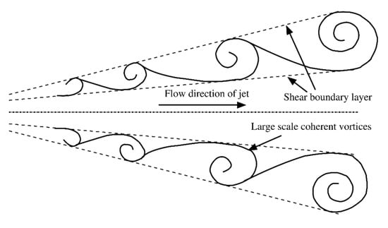
Figure 1.
Formation of the coherent vertical structure in the streamwise direction.
Due to their apparent advantages, jets find their use in high-speed military and passenger aircraft. In particular, due to various applications, the circular jet discharged from the convergent–divergent nozzle is investigated in great detail to realize the mechanism of jet mixing and to determine its characteristics. An enhanced jet mixing increases the efficiency of an aircraft engine significantly. Thus, to promote the jet mixing, various control strategies have attracted the attention of many researchers to optimize their beneficial impact. In addition, the thermal signature and the noise characteristics of the nozzle exhaust must be carefully controlled to enhance the stealth capability of the high-speed aircraft. A proven way to achieve this is by reducing the supersonic core of the jet exiting the nozzle through mixing enhancement [7,8,9]. In addition, an improved jet mixing is found to have a direct influence on diffusing the heat signature [7,10]. As core length reduction and noise attenuation are mostly dependent on shock cells and vortical structures, it is essential to alter or distort them by introducing small-scale mixing-promoting vortices. Implementation of vortex generators is a well-established control technique that improves the mixing of jets by shedding streamwise vortices. A tab is a flat metal strip that is usually deployed at the exit of the nozzle to promote the mixing behavior (Figure 2). Several researchers have investigated the efficacy of the plain tab, which was deployed at the outlet of the axisymmetric nozzle of convergent–divergent type. Zaman et al. (1994) stated that the simple tabs, placed in the diametrically opposite position of the exit plane of the nozzle, significantly improve the mixing and thus reduce the supersonic core length [11]. In another study, Zaman (1993) demonstrated that the primary source of mixing-promoting counter-rotating vortices is the upstream ‘pressure hill’ formed by the flow deceleration caused by the tab [12]. Subsequently, detailed experimental investigations were conducted by Greeta and Smith (1993) and Reeder and Samimy (1996) to study the production of the vortex-structures in the neighborhood of the exit of the nozzle. They confirmed that the tabs generate the counter-rotating azimuthal vortices that eventually become streamwise at a particular downstream location due to flow inertia [13,14].
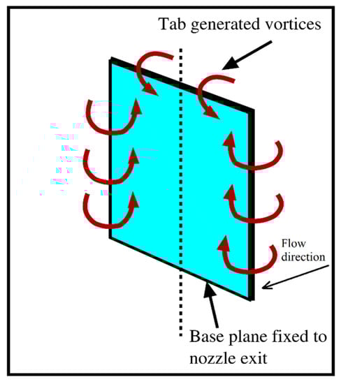
Figure 2.
Mixing-promoting vortex shedding from a rectangular tab.
At this stage, we should note that the tabs used in the above studies had a single aspect ratio and, therefore, offered a constant blockage to the flow. Therefore, to investigate the effects of varying geometric blockage, Kaushik and Rathakrishnan (2015) tested the tabs of rectangular shape with different aspect ratios mounted at the Mach 1.73 nozzle exit. They concluded that the aspect ratio of the tab provides a significant impact on jet mixing [15]. Further, Khan et al. (2020) noticed that the orientation of tabs influences the jet mixing effectiveness significantly [16]. Although the deployment of tabs promotes the mixing, they are associated with a large amount of thrust loss. The quantification of the thrust loss is documented by Lovaraju and Rathakrishnan (2006). In that investigation, it is documented that the amount of thrust loss is nearly the same as the geometric blockage offered by the tabs [17].
We must note that the tab of the uniform cross-section sheds vortices of uniform size. However, in the literature, it is well-established that vortices of mixed-size are more advantageous from a mixing point of view than eddies of the same size. Thus, it would be more advantageous if the tab geometry could be modified in such a way that it can produce vortices of varying strength and size [18]. According to vortex theory, the strength and size of vortices depend on the half-width of the tab from which they are produced. Thus, the variation in the tab’s half-width can promote the generation of vortices. One way of achieving this is by providing corrugations along the tab edges, which, in turn, vary the half-width of the tab Kaushik and Rathakrishnan (2013) were the first in investigating the three geometries of corrugations, namely, rectangular, semicircular, and triangular, along the tab edges [19]. They found that the efficacy of semicircular corrugated tabs in promoting mixing is much superior to the tabs with rectangular and triangular corrugations. They postulated that the number of corners in these corrugation geometries is responsible for their behavior. In this study, however, they tested the tabs of a single aspect ratio.
In addition, Kumar and Rathakrishnan (2013) and Akram and Rathakrishnan (2018) investigated the efficacy of the plain and corrugated triangular tabs used at the outlet of the circular nozzle at different levels of expansion. They observed that the corrugation tab has a superior ability to promote mixing than a simple triangular tab. However, when introduced at the exit of the nozzle, the performance of corrugated triangular tabs is not prominent [20,21].
In addition to the corrugations along the tab edges, it can also be envisaged from vortex dynamics that the mixing enhancing capability of a tab can be further increased if the vortices shed from it can be fetched near to the jet centerline. Besides, to the best of the authors’ understanding, only the work of Chiranjeevi and Rathakrishnan (2010) evaluated the efficacy of square corrugations along the edges of a plain rectangular tab [22]. The results showed the superiority of square corrugations. However, it did not provide a comparative analysis of different corrugation geometries on the jet mixing. In particular, the study did not record the impact of semicircular or triangular types of corrugations on the tab edges.
Taking these observations into account, in the current study, two rectangular tabs with corrugations along the edges of the tab, mounted at the outlet of a Mach 1.73 axisymmetric nozzle, are experimentally studied in overexpanded, correctly expanded, and underexpanded conditions of the jet. Three types of corrugation geometries, i.e., rectangular, triangular, and semicircular, are configured along the tab edges. To obtain different levels of expansion at the nozzle outlet, the nozzle pressure ratio (NPR) is varied from 4 to 8, in steps of one. This study is carried out in three parts. First, the reduction in supersonic core length is quantified by measuring the decay in total pressure along the jet centerline for all tab configurations. Second, the influence of corrugated geometry on the rate of jet spread in the directions—along tab orientation and perpendicular to tab orientation—is studied by plotting the pressure profiles. Finally, the effect of the different corrugation geometries on the waves that exist in the core is qualitatively studied using the shadowgraphic flow visualization technique.
2. Experimental Methodology
The experiments are carried out in an open jet-test arrangement as schematically represented in Figure 3. Pressurized air was delivered from the storage tank to the settling chamber through a series of control and pressure regulating valves. The diameter and length of the settling chamber were 300 and 600 mm, respectively. The settling chamber was fitted with two wire-mesh screens in order to reduce the level of turbulence before the flow enters into the nozzle. The expansion level at the nozzle outlet was varied through the pressure regulating valve (PRV).
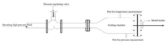
Figure 3.
Schematic layout of the supersonic jet-test arrangement.
This study explores the efficacy of a plain and the corrugated tabs on the mixing behavior of a Mach 1.73 jet at overexpansion, near-correct-expansion, marginal-underexpansion, and high-underexpansion conditions corresponding to NPR 4, 5, 6, 7, and 8, respectively. For the present investigation, a convergent–divergent circular nozzle, calibrated to Mach 1.73, is used. A schematic representation of the nozzle with the base plate is shown in Figure 4. The diameters of the throat and exit of the designed nozzle are 10 and 13 mm, respectively. The flow Reynolds numbers, based on the outlet diameter of the nozzle, is found to be 6.2 million at NPR 4 and 1.3 million at NPR 8, respectively. As these Reynolds numbers are much higher than the troublesome number of 500, the effect of viscosity on pressure measurements was insignificant. Essentially, a Reynolds number below 500 is troublesome for pressure measurement as the flow at that condition is dominated by the viscous effect. Hence, the Reynolds number below 500 is referred to as the troublesome number [23,24].
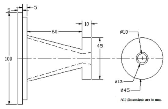
Figure 4.
Schematic diagram of the supersonic nozzle attached with the base plate.
Pressure measurements were performed using a pitot probe, which is placed on a three-dimensional traverse system (Figure 5). The traversing mechanism had six degrees of freedom with an accuracy of ±0.1% along all three axes. The inner and outer diameters of the pitot probe were respectively 0.4 and 0.6 mm. The geometric blockage offered by the probe was estimated to be 469.5, well above the blockage limit of 64 [10]. The errors associated with the pressure measurement due to geometric blockage were, therefore, negligibly small. Here, we should note that a pitot pressure probe essentially estimates the total pressure downstream of the bow-shock formed just upstream of the probe nose (Figure 5). Therefore, to obtain the total pressure under freestream conditions, one must account for a drop in pressure across the bow-shock. However, the calculation of the pressure drop across the shock wave is a cumbersome task as the incoming Mach number varies continuously due to the complex structure of the shock cells. Moreover, even though the actual freestream pressure is not estimated, the measured pitot pressures downstream of the bow-shock are good enough for qualitative analysis of the flow field.
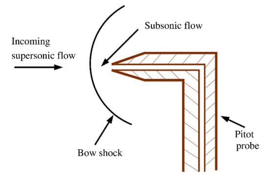
Figure 5.
Formation of the bow-shock at the probe nose.
The pitot probe, facing the flow field, was connected to a 16-channels pressure scanner (model number PSI 9010), which is capable of measuring pressures up to 2.1 MPa. The transducer can average up to 250 samples per second to give a single mean pressure value. After the ‘re-zero calibration,’ the accuracy of the transducer is ±0.15 of the full scale. The repeatability of pressure measurement is ±3%.
Two rectangular corrugated tabs of an aspect ratio of 1.5 were deployed diametrically opposite to each other at the outlet of a Mach 1.73 circular nozzle with an exit diameter of 13 mm (Figure 6). The tabs were made of a 1 mm-thick sheet of brass. They were attached to the exit plane of the nozzle and protruded perpendicularly to the flow direction. Three types of corrugation geometries, namely, rectangular, semicircular, and triangular, were configured along the tab edges, as depicted in Figure 7. The geometric blockage provided by all the tabs was kept below 5% to minimize the loss of thrust. The blockage ratio for each tab is shown in Table 1. It should be noted that, for an appropriate comparison of the efficacy between the different corrugation shapes, each tab must have a constant blockage of 2.5%; therefore, corrugated geometries are manufactured with optimum dimensions. In addition, it should be noted that, instead of two corrugations on either side of the tab (such as semicircular and triangular corrugated tabs), a single rectangular corrugation is provided along the tab width due to manufacturing limitations. Nevertheless, this type of geometry is indeed reasonable, as the shedding of the streamwise vortices near the jet centerline has been shown by several researchers to be more effective in encouraging the mixing [25,26]. Therefore, instead of two corrugations along the edges of the tab, a single rectangular corrugation geometry over the tip of the tab is reasonably accurate as it has similar effects on jet mixing. It should be noted that semicircular and triangular corrugation geometries are formed 2 mm from the top and bottom edges of the tab.
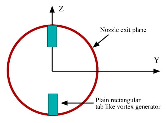
Figure 6.
Rectangular tabs of aspect ratio 1.5 deployed at the nozzle exit.
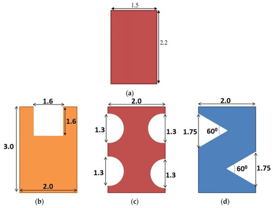
Figure 7.
The tabs of aspect ratio 1.5 with different corrugation geometries along the edges (all dimensions are in mm). (a) Plain tab (b) Rectangular corrugated tab (c) Semicircular corrugated tab (d) Triangular corrugated tab.

Table 1.
Blockage ratio associated with each tab.
The total pressures were estimated along the streamwise direction (X-direction) at different locations at 1 mm intervals, up to 25D. When a supersonic jet is discharged into the surrounding atmosphere, three distinct flow conditions can be observed. The jet will be overexpanded if the pressure at the nozzle exit (Pe) is less than the surrounding or backpressure (Pb), i.e., Pe < Pb; will be correctly expanded if Pe = Pb; or will be underexpanded if Pe > Pb. For the Mach 1.73 jet, the nozzle pressure ratio (NPR) of 5.17 is associated with the correctly expanded state. Therefore, for NPR 4, 5, 6, 7, and 8, the Mach 1.73 jet is said to be overexpanded, almost correctly expanded, marginally underexpanded, underexpanded, and highly underexpanded, respectively.
3. Results and Discussions
Both quantitatively and qualitatively, the effects of the tab on supersonic core length and wave structure are investigated in this study. A core length decrement is quantified by plotting the nondimensionalized total pressures estimated along the jet-axis against the nondimensional axial distances. The measured pitot pressure (p) is nondimensionalized using the settling chamber pressure (p0), and the axial distance (X) and the transverse distance (Y) are nondimensionalized with the nozzle exit diameter (D). Qualitative analysis of the wave structure in the supersonic core is performed utilizing the shadowgraph flow visualization technique, and the images are captured by a stationary camera.
3.1. Centerline Pressure Decay
In jet literature, it is well-established that the centerline pressure decay plot is an efficient tool for capturing core length, decay characteristics, and fully developed zones. Higher pressure decay confirms the faster mixing of jets. Furthermore, the core length of the supersonic jet (considered to be the axial distance from the outlet of the nozzle to the location of the beginning of the characteristic decay), estimated from the centerline total pressure plot, can directly describe the efficiency of the jet mixing. As already discussed, three types of configuration geometries, namely, semicircular, rectangular, and triangular corrugation geometries on the edges of a plain rectangular tab, deployed at the outlet of a Mach 1.73 nozzle, are compared for their mixing-promoting capability.
Shadowgraphic images for the overexpanded and underexpanded conditions of a typical uncontrolled jet are shown in Figure 8a,b, respectively. In these figures, the waves and the shock-cell structures are clearly represented. Further, the reduction in jet centerline pressure for both uncontrolled and controlled jets are given in Figure 9, Figure 10, Figure 11, Figure 12 and Figure 13. The tab with aspect ratio 1.5 is very effective in shedding mixing-promoting vortices along the sides at the nozzle exit from the wall to about 46% of the length of the nozzle exit radius, from opposite ends. In the pressure distribution along the centerline of the uncontrolled jet, the crest and trough of the pressure distributions confirm the existence of shock and expansion waves within the supersonic core. The nozzle exit pressure for an overexpanded jet is lower than the backpressure. Therefore, the flow at the nozzle outlet must be compressed to be balanced with the ambient. This balance is essentially achieved by generating oblique shock waves at the outlet (Figure 8a). After a certain downstream distance, these oblique shocks cross each other at the jet axis and are reflected as expansion waves from the jet boundary. It should be noted that, in addition to oblique shocks, the flow experienced expansion waves at the outlet of the nozzle due to the flow relaxation that occurred shortly after discharge from the nozzle [10]. In Figure 9, as the jet is overexpanded, initially, the pitot pressure decreases from the value at the exit of the nozzle due to the generation of oblique shock waves at the nozzle outlet. As a decrease in total pressure (in the downstream location of the shock wave) implies a rise in the Mach number upstream of the wave, it can be said that the flow first accelerates after exiting the nozzle. Moreover, at a certain downstream location, the drop in pressure reaches its minimum, which essentially corresponds to the maximum flow speed. Note that it is the first shock cross-over point where the left and right running oblique shock waves (generated at the exit of the nozzle) cross each other. Downstream of this point, the jet becomes subsonic and accelerates further due to the transfer of momentum from the higher-momentum fluid at the periphery. Correspondingly, the pitot pressure rises to its maximum value, where the flow becomes first sonic and then supersonic. From this point onward, the pressure drops again until the flow meets the second shock cross-over point, and the cycle repeats, leading to a shock-cell structure in the supersonic core. The length of the shock cell is defined as the distance between two successive peaks or troughs in a centerline pressure decay plot.
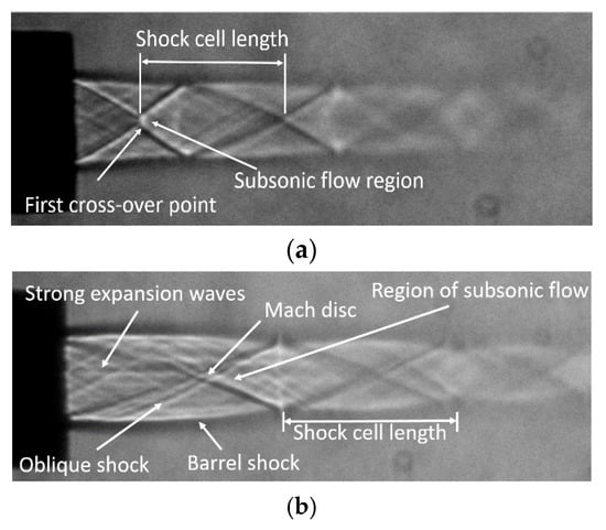
Figure 8.
Shadow graphic views of the uncontrolled Mach 1.73 jet. (a) Overexpanded jet (nozzle pressure ratio (NPR) 4). (b) Underexpanded jet (NPR 7).
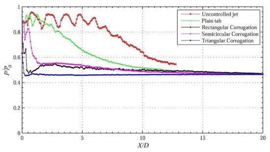
Figure 9.
The decay of jet centerline pressure for Mach 1.73 jet at NPR 4.
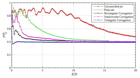
Figure 10.
The decay of jet centerline pressure for Mach 1.73 jet at NPR 5.
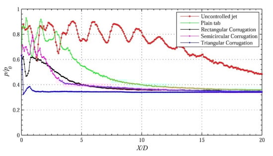
Figure 11.
The decay of jet centerline pressure for Mach 1.73 jet at NPR 6.
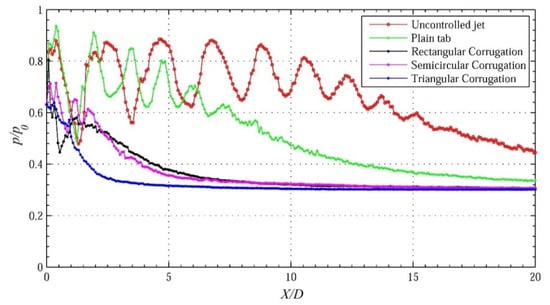
Figure 12.
The decay of jet centerline pressure for Mach 1.73 jet at NPR 7.
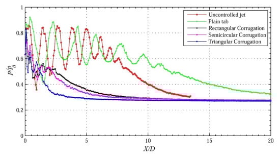
Figure 13.
The decay of jet centerline pressure for Mach 1.73 jet at NPR 8.
At the favorable pressure gradient that corresponds to NPR 7, the length of the core is increased significantly (more than the axial location of X/D = 15) for the uncontrolled jet, as observed in Figure 12. The structure of the shock cells becomes longer; the shock and the expansion waves become more intense, and characteristic decay remains even beyond the streamwise distance of 20D. The shock cells in the uncontrolled jet core possess expansion waves of higher strength due to the two sources of expansion: The underexpansion level and the relaxation effect [10]. Shadowgraphic images at NPR 7 show a longer first shock cell that has waves of considerable strength (Figure 8b) compared to the overexpanded condition of the jet (Figure 8a).
Further, the results for the overexpanded condition corresponding to NPR 4 (Figure 9) reveals that the triangular corrugated tab is a superior mixing promoter among the corrugation geometries investigated. It is also observed that all the corrugation geometries are performing much better than the plain tab without corrugations. For the plain tab, the core length is about 3D, whereas, for the semicircular corrugated tab, it is slightly less than 1D. For the rectangular corrugated tab, it is about 0.5D, and for the best-performing triangular corrugated tab, the core length is approximately zero.
Once again, for the correctly expanded jet (NPR 5), the results in Figure 10 show that the triangular corrugated tab is the superior mixing promoter followed by the rectangular and semicircular corrugated tabs and the plain tabs.
At a favorable pressure gradient of 14% corresponding to NPR 6 (Figure 11), the mixing of all corrugation geometries is good. Among them, the best mixing promoter is the triangular corrugated tabs. However, the core lengths of tabs with rectangular and triangular corrugations are of a comparable magnitude of approximately 1D.
At an expansion level of 33% (NPR 7), the mixing introduced by the triangular corrugated tab remains higher in both near and far-field locations (Figure 12). At the end of the characteristic decay zone, the mixing caused by semicircular and rectangular corrugations is almost the same. It is, however, marginally inferior to triangular corrugations.
At the maximum NPR tested in the present study, i.e., NPR 8, which is associated with a favorable pressure gradient of 52%, the results are presented in Figure 13. The figure confirms that the corrugated tab is the superior mixing promoter in all three zones. One interesting feature of this NPR is that the plain tab results in a core of about 4D longer than the uncontrolled jet.
From these findings, it is evident that, when the mixing enhancing vortices are shed near to the jet-axis, the efficacy of corrugations is superior compared to the situation where the vortices are shed considerably away from the jet-axis. In addition, for aspect ratio 1.5, the triangular corrugated tab is recognized to be superior in promoting the jet mixing than the other corrugation geometries in the existence of adverse, zero, and favorable pressure gradients. The reason for its improved efficacy can be envisaged as follows. It is well-understood from vortex dynamics that the size of a vortex produced by the surface is proportional to the radius of the curvature of the surface itself. As a result, the size and shape of the vortices generated from the tab are proportional to the half-width of the latter. A tab of constant width (plain tab) will produce vortices of uniform size, while a tab with corrugation geometries on its edges will shed vortices of mixed-size. These small-scale mixed-size vortices ensure superior mixing. As a result, the corrugated tabs are more effective in promoting mixing in comparison to the plain tab. Moreover, it can be seen that triangular corrugations can produce a more nonuniform vortex structure compared to the rectangular and semicircular corrugated tabs due to continuous change in the half-width of the corrugated edges. Thus, the triangular corrugated tab is the most effective in mixing enhancement [11,19].
To calculate the mixing-promoting efficiency of the plain and corrugated tabs, the decrease in the supersonic core lengths (%) at different NPRs is calculated using Equation (1). The results obtained are tabulated in Table 2 and plotted in Figure 14. As a typical jet feature, the length of the supersonic core spreads with an increase in NPR. However, when the corrugation tabs are introduced at the nozzle outlet, the core length decreases in all the cases, with a maximum decrease for triangular corrugations at NPR 5 (correct-expansion). That is, the tab with triangular corrugations is most efficient in decreasing the core length. The effectiveness of a corrugated tab can be estimated from Equation (2). The percentage reduction in core lengths due to corrugated tabs over the plain tab at different NPRs are tabulated in Table 3 and plotted in Figure 15. It is noteworthy that the triangular corrugations are efficient at various levels of expansions, except NPR 8, where rectangular corrugations demonstrate the superior performance. Nevertheless, further investigations are necessary to explain the contradicting behavior of the triangular corrugations at highly underexpanded conditions.
Table 2.
Percentage reduction in core lengths at different NPRs.
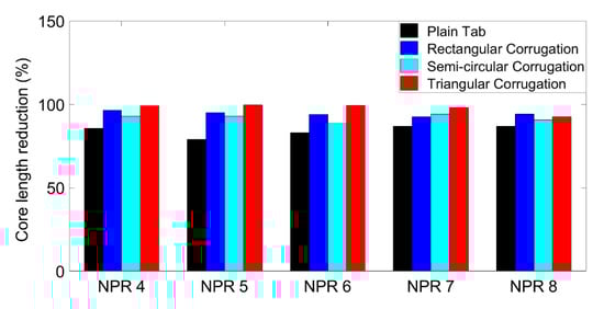
Figure 14.
Percentage reduction in core length for controlled jets.
Table 3.
Percentage effectiveness of corrugation geometries over the plain tab at different NPRs.
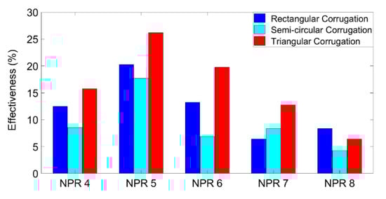
Figure 15.
Percentage effectiveness of corrugation geometries over the plain tab.
3.2. Pressure Profiles
One of the most detrimental issues associated with the tab-controlled jet is the asymmetry in the flow field due to the vortex-induced control mechanism, where each vortex corresponds to its frequency and amplitude. Besides, the entropy generation is very high as a result of the enhanced mixing process. Therefore, in addition to producing proper mixing, the control mechanism should not introduce any severe asymmetry to the flow domain. In order to investigate this vital aspect, the pressure profiles were measured in the directions—perpendicular to tab orientation and along tab orientation—for the controlled jets, and along the radial direction for the uncontrolled jet. The measured pitot pressures (p) are made nondimensional with the pressure of the settling chamber (p0) and plotted against the nondimensional radial distances, i.e., perpendicular to tab orientation (Y/D) and along tab orientation (Z/D).
Pressure profiles for tabs with an aspect ratio of 1.5 at NPR 4 are shown in Figure 16a–d. In the vicinity of the exit of the nozzle (X/D = 0.5), under the adverse pressure gradient, all corrugated tabs exhibit significant asymmetry in the direction normal to the tab orientation. Still, in the direction along the tab orientation, the asymmetry caused by corrugated tabs is only marginal (Figure 16a). When the axial distance increases to 1D, as shown in Figure 16b, the jet attempts to regain its symmetry for all corrugation geometries. With the further increase in axial distance (X/D = 2.0), the spread for the semicircular corrugated tab is the largest in both directions (perpendicular to tab orientation and along tab orientation). As the axial distance increases further (X/D = 4.0), as shown in Figure 16d, the spread for the semicircular corrugated tab continues to be the largest, and the pressure levels are significantly higher than for the triangular and rectangular corrugated tabs. Indeed, in the direction along the tab orientation, the triangular corrugations produce a fully developed flow as early as X = 4D.
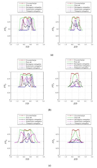
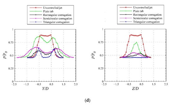
Figure 16.
Pressure profiles for Mach 1.73 jet at NPR 4 (overexpanded). (a) Perpendicular to tab orientation; along tab orientation. X/D = 0.5. (b) Perpendicular to tab orientation; along tab orientation. X/D = 1. (c) Perpendicular to tab orientation; along tab orientation. X/D = 2. (d) Perpendicular to tab orientation; along tab orientation. X/D = 4.
The pressure profiles for NPR 5 are shown in Figure 17a–d. At X/D = 0.5, even at this correctly expanded state, the jet exhibits considerable asymmetry in both directions for all corrugated tabs, which is similar to the case of NPR 4. In addition, the jet spread for the semicircular corrugated tab is maximum in the direction perpendicular to the tab orientation. At X/D = 1.0, the semicircular corrugated tab continues to enjoy the largest spread (Figure 17b). In addition, the pressure levels for all the corrugated tabs are comparable except in the zone around the jet axis. With an additional increase in the streamwise distance (X/D = 2.0), as in Figure 17c, all the corrugated tabs result in a considerably larger spread as expected; however, at this streamwise location also, the spread for the semicircular corrugated tab is maximum. Another interesting feature noticed is that the pitot pressure levels for the corrugated tabs are considerably lower than the pressure levels of the plane tab, both along the tab orientation and perpendicular to the tab orientation. At X = 4D (Figure 17d) also, the spread caused by the semicircular type of corrugated tab is observed to be the largest. However, along the tab orientation, the tab with triangular corrugations establishes a fully developed state, whereas the rectangular and semicircular corrugated tabs are still in the characteristic decay zone.
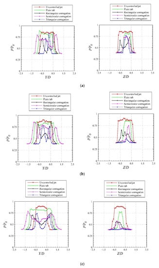
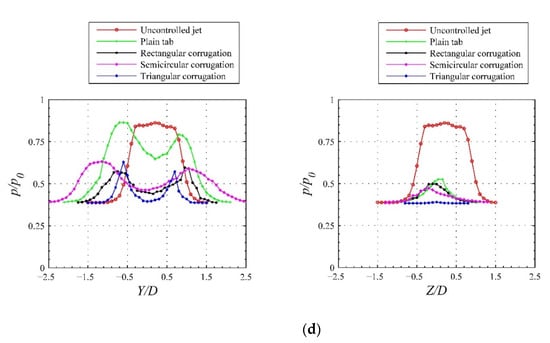
Figure 17.
Pressure profiles for Mach 1.73 jet at NPR 5 (correctly expanded). (a) Perpendicular to tab orientation; along tab orientation. X/D = 0.5. (b) Perpendicular to tab orientation; along tab orientation. X/D = 1. (c) Perpendicular to tab orientation; along tab orientation. X/D = 2. (d) Perpendicular to tab orientation; along tab orientation. X/D = 4.
In the presence of underexpansion conditions corresponding to NPR 7, at X/D = 0.5, the pressure profiles in both the directions fluctuate at different radial locations. In addition, the jet-field is asymmetrical (Figure 18a). At X = D (Figure 18b), the jet pressure field of the uncontrolled jet is oscillatory and asymmetrical; however, the field tries to regain its symmetry for all the corrugated tabs. At the streamwise location of X = 2D, the oscillatory nature of pressure distribution comes down considerably in both directions, perpendicular to the tab orientation and along the tab orientation (Figure 18c). In addition, the spread for the semicircular corrugated tab is maximum perpendicular to the tab orientation. At X = 4D (Figure 18d), in the direction perpendicular to the tab orientation, the spread caused by the tab with semicircular corrugations is the largest, followed by the triangular and rectangular corrugations. However, along the tab orientation, the pressure levels around the jet axis for the triangular corrugated tabs are noticeably lower than those for the semicircular and rectangular corrugated tabs. As seen in the previous axial locations, for this location also, the corrugated tabs cause the jet to assume almost a developed profile.
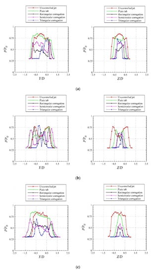
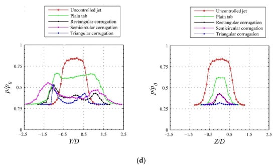
Figure 18.
Pressure profiles for Mach 1.73 jet at NPR 7 (underexpanded). (a) Perpendicular to tab orientation; along tab orientation. X/D = 0.5. (b) Perpendicular to tab orientation; along tab orientation. X/D = 1. (c) Perpendicular to tab orientation; along tab orientation. X/D = 2. (d) Perpendicular to tab orientation; along tab orientation. X/D = 4.
In the pressure plots, the jet bifurcation is essentially represented by two separated pressure peaks, which are continuously diminishing as the jet moves downstream in order to attain the fully developed state. Although the plain tabs produce intense vorticity in the near-exit plane of the nozzle, the corrugated tabs produce the vortices of mixed-size that effectively reduce the flow asymmetry compared to the plain tabs. In fact, the semicircular corrugations are found to be most efficient in reducing the asymmetry compared to other corrugation geometries. For all the three expansion conditions, it is interesting to see that the semicircular corrugated tab spreads the jet at a faster rate in the direction perpendicular to the tab orientation compared to all other configurations. Further, it can be seen that the uncontrolled jet spread rate is higher than those of the tab-controlled jets, in the direction along the tab orientation, at all NPRs. This may be because the blockage introduced by the tab restricts the spreading along the tab orientation. Even then, the jet decay is higher for all tab-controlled jets, particularly for the tab with triangular corrugation along its edges, as can be observed in the centerline pressure decay.
3.3. Flow Visualizations
The waves in the supersonic core of uncontrolled and controlled jets are visualized by the shadowgraph technique. In the case of an uncontrolled jet, the visualization was carried out in a direction perpendicular to the flow, whereas in the case of controlled jets, visualizations were recorded along the tab orientation (X–Z plane) and perpendicular to the tab orientation (X–Y plane). The shadowgraph image at the adverse pressure gradient (NPR 4) is shown in Figure 19a–e. It can be seen that the plain tab (Figure 19b) could reduce the shock cells compared to the uncontrolled jet. However, when rectangular corrugations are provided on the tab edges, waves in the jet field are found to be extremely weak, as shown in Figure 19c. In addition, along the tab orientation, the jet shows bifurcation, which is more prominent for the semicircular corrugated tab (Figure 19d). However, in the near-field (closer to the exit of the nozzle), the waves prevailing in the core are stronger than the jet controlled with the rectangular corrugated tab. Besides, along the tab orientation, the spread is larger than that of the rectangular corrugated tab. In the case of the triangular corrugated tab, the spread is found to be larger, and the bifurcation is observed to be prominent compared to the rectangular and semicircular corrugated tabs.
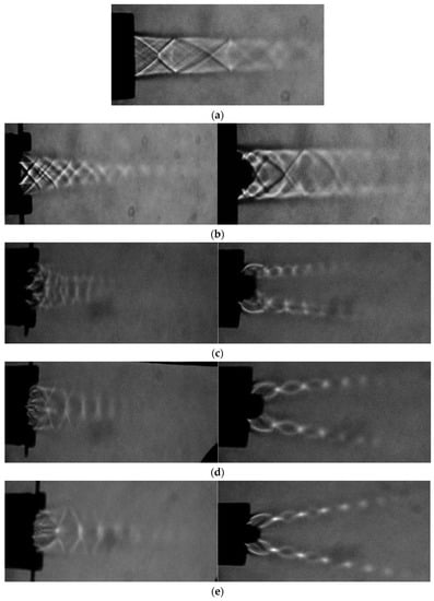
Figure 19.
Shadowgraphic views of the uncontrolled and controlled Mach 1.73 jets at NPR 4 (overexpanded). (a) Uncontrolled jet. (b) Along tab orientation. Perpendicular to tab orientation. Plain tab (c) Along tab orientation. Perpendicular to tab orientation. Rectangular corrugated tab (d) Along tab orientation. Perpendicular to tab orientation. Semicircular corrugated tab (e) Along tab orientation. Perpendicular to tab orientation. Triangular corrugated tab.
When there is a favorable pressure gradient at the outlet of the nozzle, analogous to NPR 7, the results of visualization, as shown in Figure 20a–e, reveals the following. It can be seen that the combined effect of expansion, due to underexpansion and flow relaxation, could significantly accelerate the flow. In the uncontrolled case, the expansion fans and a barrel shock of considerable strength at the exit of the nozzle are visible. However, when corrugated tabs are mounted, the barrel becomes comparatively weaker and shorter, as shown in Figure 20c–e. In the existence of a favorable pressure gradient, the plain tab could significantly improve the mixing after some downstream location (Figure 20b). In addition, three clear shock cells with waves of significant strength are observed with a jet controlled with a plain tab. However, for all the corrugated tabs, only the first shock cell appears to be prominent, followed by shorter cells with weaker waves. For rectangular corrugations (Figure 20c), it is interesting to see that the mixing is greatly enhanced even in the near-field of the nozzle exit, and only one noticeable shock cell appears in both the directions, along the tab orientation and normal to the tab orientation. For the semicircular corrugated tab (Figure 20d), it is shown that the near-field mixing is better than the rectangular corrugated tab, and the jet is bifurcated. For the triangular corrugated tab (Figure 20e), mixing is recorded to be the best in both near- and far-fields. However, the semicircular corrugated tab is the most efficient way to diffuse waves in the jet field.
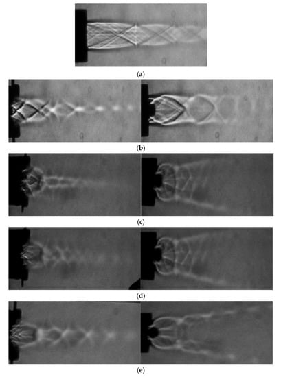
Figure 20.
Shadowgraphic views of the uncontrolled and controlled Mach 1.73 jets at NPR 7 (underexpanded). (a) Uncontrolled jet. (b) Along tab orientation. Perpendicular to tab orientation. Plain tab (c) Along tab orientation. Perpendicular to tab orientation. Rectangular corrugated tab (d) Along tab orientation. Perpendicular to tab orientation. Semicircular corrugated tab (e) Along tab orientation. Perpendicular to tab orientation. Triangular corrugated tab.
From the above discussion, we can see that the waves in controlled jets are greatly altered in both directions and that the supersonic zone near the jet-axis is narrowed down in the direction perpendicular to the tab orientation. However, the supersonic field is stretched along the tab orientation. This differential spread in two different directions (i.e., perpendicular to tab orientation and along tab orientation) can be favorable from a mixing point of view as any differential shear could inevitably result in an early axis switch (Figure 21) and result in faster mixing.
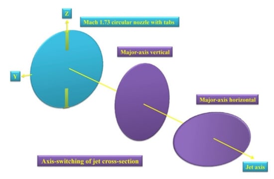
Figure 21.
Axis-switch phenomena in a jet.
The axisymmetric jet controlled by the tab is bifurcated into two separate streams on either side of the tab at all levels of expansion. These two noncircular streams, which have their supersonic cores with quasi-periodic shock-cell structures, are considered to be the daughter streams [16]. The bifurcation of a circular jet into daughter streams is shown schematically in Figure 22. The flow deceleration caused by the implementation of the tabs at the exit plane of the nozzle results in an upstream ‘pressure hill,’ which is the possible reason for jet bifurcation. Along with intense vortex activity, the daughter streams are also responsible for the rapid spread of the jet and the rapid decay in the supersonic core. Notice that the daughter-streams, produced by the jet bifurcation, do not merge. Instead, they diverge due to their high inertia. It is easy to note that, compared to the plain tab, the bifurcation of jets is significantly prominent for corrugated tabs. This is due to the intense vortex activity due to the introduction of the corrugation geometry in the jet flow field. Essentially, the mixed size vortices from the additional sharp corners cause more intense interactions locally with the incoming flow, which might result in early jet bifurcation.
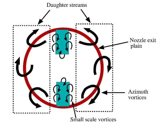
Figure 22.
Schematic diagram of the jet bifurcation and daughter streams.
It is noted from the literature that the deployment of the semicircular and rectangular corrugated tabs of aspect ratio 1.0 at the outlet of the nozzle produces efficient mixing, particularly at overexpanded conditions [10,19]. By contrast, the triangular corrugated tabs of aspect ratio 1.5 showed superior performance by encouraging the mixing at the correctly expanded state. Here, both the rectangular and the semicircular corrugated tabs of aspect ratio 1.5 are associated with the azimuthal vortex shedding from four sharp corners (closely spaced). However, for the same aspect ratio, the triangular corrugated tab is associated with the vortex shedding from three sharp corners (closely spaced), as shown in Figure 23. As a greater number of sharp corners result in additional interactions among the vortices, a higher reduction in their strength is inevitable. As a consequence, the triangular corrugated tab of aspect ratio 1.5 is observed to be a superior mixing promoter.
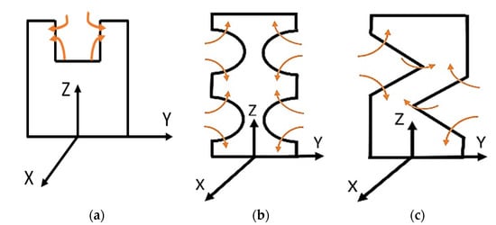
Figure 23.
Azimuthal vortex shedding from the corrugated tabs. (a) Rectangular corrugated tab (b) Semicircular corrugated tab (c) Triangular corrugated tab.
The distortion of shock-cell structures within the core has also been shown to be effective in noise mitigation [8,9]. In addition, it is well-established that the weakening of shock waves suppresses the noise associated with the shock [27,28,29]. Therefore, it can be concluded that wave attenuation using corrugated tabs can augment the jet mixing and reduce the shock-associated noise.
4. Conclusions
In the present study, an attempt is made to quantify the effectiveness of plain rectangular tabs of aspect ratio 1.5 with various corrugation geometries on Mach 1.73 jet mixing. From the outcomes of the present investigation, it is observed that the corrugated tabular actuator performs exceptionally well in reducing the supersonic core and weakening the waves over their uncorrugated counterparts. At overexpansion, near-correct-expansion, and marginal-underexpansion conditions, the triangular corrugated tabs are observed to be very effective. As high as a 99.7% decrease in core length is accomplished by the tab with triangular corrugations at the near-correct-expansion condition. However, at the high-underexpansion condition, the triangular corrugation geometry does not perform well in reducing the supersonic core length. Although a plain tab introduces significant asymmetry to the jet due to intense vortex activity, the tab with corrugations brings the symmetry back to the jet field by shedding the small-scale mixing-promoting vortices. The semicircular corrugated tab is most effective in suppressing flow asymmetry, especially in near-field locations, compared to other corrugation geometries. The waves that exist in the core of controlled jets are weakened, and the shock cells are compressed by the corrugated tabs. From the perspective of the aeroacoustic noise generation, it is an advantage as lessening the shock cells and weakening the strength of the waves could lead to shock-associated noise suppression.
Author Contributions
All the authors have contributed their efforts to complete the paper. T.T. performed the experimental investigation; T.J. analyzed the results and wrote the first draft. M.K. supervised the work, and reviewed and edited the manuscript. All authors have read and agreed to the published version of the manuscript.
Funding
This research received no external funding.
Acknowledgments
The authors deeply acknowledge the Indian Institute Technology Kanpur for providing the experimental facility, which helped immensely in completing the present study.
Conflicts of Interest
The authors declare no conflict of interest.
Nomenclature
| AR = Aspect ratio |
| CPD = Centerline pressure decay |
| D = Nozzle exit diameter |
| M = Nozzle exit Mach number |
| NPR = Nozzle pressure ratio |
| P = Pitot pressure |
| pb = Back-pressure |
| pe = Nozzle exit pressure |
| p0 = Stagnation pressure in the settling chamber |
| X = Streamwise direction |
| Y = Perpendicular to tab orientation |
| Z = Along tab orientation |
References
- Brown, G.L.; Roshko, A. On density effects and large structure in turbulent mixing layers. J. Fluid Mech. 1974, 64, 775–816. [Google Scholar] [CrossRef]
- Dimotakis, P.E.; Brown, G.I. The mixing layer at high Reynolds number: Large-structure dynamics and entrainment. J. Fluid Mech. 1976, 78, 535–560. [Google Scholar] [CrossRef]
- Yule, A.J. Large-scale structure in the mixing layer of a round jet. J. Fluid Mech. 1978, 89, 413–432. [Google Scholar] [CrossRef]
- Dimotakis, P.E.; Miake-Lye, R.C.; Dimitris, A.P. Structure and dynamics of round turbulent jets. Phys. Fluids 1983, 26, 3185. [Google Scholar] [CrossRef]
- Liepmann, D.; Gharib, M. The role of streamwise vorticity in the near-field entrainment of round jets. J. Fluid Mech. 1992, 245, 643–668. [Google Scholar] [CrossRef]
- Barre, S.; Quine, C.; Dussauge, J. Compressibility effects on the structure of supersonic mixing layers: Experimental results. J. Fluid Mech. 1994, 259, 47–78. [Google Scholar] [CrossRef]
- Bradbury, L.J.S.; Khadem, A.H. The Distortion of a Jet by Tabs. J. Fluid Mech. 1975, 70, 801–813. [Google Scholar] [CrossRef]
- Tam, C.K.W. Supersonic jet noise. Annu. Rev. Fluid Mech. 1995, 27, 17–43. [Google Scholar] [CrossRef]
- Ahuja, K.K.; Brown, W.H. Shear Flow Control by Mechanical Tabs. AIAA Pap. 1989, 89, 994. [Google Scholar]
- Kaushik, M. Innovative Passive Control. Techniques for Supersonic Jet Mixing, 1st ed.; Lambert Academic Publishing: Saarbrucken, Germany, 2012; ISBN 978-3-659-27608-8. [Google Scholar]
- Zaman, K.; Reeder, M.; Samimy, M. Control of axisymmetric jet using vortex generators. Phys. Fluids 1994, 6, 778–793. [Google Scholar] [CrossRef]
- Zaman, K.B.M.Q. Streamwise Vorticity Generation and Mixing Enhancement in Free jets using Delta Tabs. Aiaa Pap. 1993, 93, 3253. [Google Scholar]
- Gretta, W.; Smith, C. The flow structure and statistics of a passive mixing tab. J. Fluids Eng. 1993, 115, 255–263. [Google Scholar] [CrossRef]
- Reeder, M.; Samimy, M. The evolution of a jet with vortex-generating tabs: Real-time visualization and quantitative measurements. J. Fluid Mech. 1996, 311, 73–118. [Google Scholar] [CrossRef]
- Kaushik, M.; Rathakrishnan, E. Tab aspect ratio effect on supersonic jet mixing. Int. J. Turbo. Jet Eng. 2015, 32, 265–273. [Google Scholar] [CrossRef]
- Khan, A.; Akram, S.; Kumar, R. Experimental study on enhancement of supersonic twin-jet mixing by vortex generators. Aerosp. Sci. Technol. 2020, 96, 105521. [Google Scholar] [CrossRef]
- Lovaraju, P.; Rathakrishnan, E. Subsonic and transonic jet control with crosswire. AIAA J. 2006, 44, 2700–2705. [Google Scholar] [CrossRef]
- Behrouzi, P.; McGuik, J.J. Effect of Tab Parameters on the Near Filed Jet Plume Development. J. Propuls. Power 2006, 22, 576–585. [Google Scholar] [CrossRef]
- Kaushik, M.; Rathakrishnan, E. Corrugated Limiting Tab for Jet Mixing. Int. J. Turbo. Jet Engines 2013, 30, 359–373. [Google Scholar] [CrossRef]
- Kumar, P.A.; Rathakrishnan, E. Corrugated triangular tabs for supersonic jet control. Part G J. Aerosp. Eng. 2014, 228, 831–845. [Google Scholar] [CrossRef]
- Akram, S.; Rathakrishnan, E. Corrugated tabs for enhanced mixing of supersonic elliptic jet. J. Aerosp. Eng. 2018, 32, 04018140. [Google Scholar] [CrossRef]
- Chiranjeevi, P.B.; Rathakrishnan, E. Corrugated tabs for supersonic jet control. AIAA J. 2010, 48, 453–465. [Google Scholar]
- Chue, S.H. Pressure probes for fluid measurement. Prog. Aerosp. Sci. 1975, 16, 147–223. [Google Scholar] [CrossRef]
- Kaushik, M. Theoretical and Experimental Aerodynamics, 1st ed.; Springer Nature: Singapore, 2019; ISBN 978-981-13-1677-7. [Google Scholar]
- Navin, K.S.; Rathakrishnan, E. Sonic Jet Control with Tabs. J. Turbo. Jet Engines 2002, 19, 107–118. [Google Scholar]
- Sreejith, R.B.; Rathakrishnan, E. Cross-Wire as Passive Device for Supersonic Jet Control. AIAA Pap. 2002, 4052, 2002. [Google Scholar]
- Ahuja, K.K. Mixing enhancement and the jet noise reduction through tabs plus ejectors. AIAA Pap. 1993, 93, 4347. [Google Scholar]
- Samimy, M.; Zaman, K.; Reeder, M. Effect of Tabs on the Flow and Noise Field of an Axisymmetric Jet. AiAA J. 1993, 31, 609–619. [Google Scholar] [CrossRef]
- Ranjan, A.; Kaushik, M.; Deb, D.; Muresan, V.; Unguresan, M. Assessment of Short Rectangular-Tab Actuation of Supersonic Jet Mixing. Actuators 2020, 9, 72. [Google Scholar] [CrossRef]


© 2020 by the authors. Licensee MDPI, Basel, Switzerland. This article is an open access article distributed under the terms and conditions of the Creative Commons Attribution (CC BY) license (http://creativecommons.org/licenses/by/4.0/).