Abstract
The technique of a larger volume of microparticle continuous separation in the acoustic field is proposed in this paper. This technique has got considerable potential with regard to the development of technologies for the portable, low-cost and non-biodegradable procedures of energy-efficient separation/purification of microparticles in biological suspension. Using a disk-shaped piezo transducer-bimorph (DSPTB) mounted on the bottom of a plastic conical fluid container (CFC), the acoustic waves (AWs) in the fluid and the eigenmodes of the CFC were excited. The AWs, induced by piezo transducer in the CFC, pushed the suspension with the microparticles upwards, which accumulated in the nodal zones of the resonating CFC walls by purifying the suspension that accumulates in the anti-nodal zones. The outlets distributed in the nodal and anti-nodal zones of the conical fluid container walls resonating on the fourth eigenmode allowed the collection of enriched or purified from microparticles suspension.
1. Introduction
The attention being paid to plasma processing technologies, and the separation of biological microparticles from it, is vital, as plasma in the human body is responsible for maintaining normal blood pressure and blood volume levels, as well as removing chemical waste from cells. Microfluidic techniques, using optical [1], magnetic forces [2], amongst others, are emerging as cost-effective and disposable tools for microparticle separation. There is also a lot of work related to ultrasonic frequency acoustic microparticle separation technologies in microchannels. Recent advances in this area have led to redesigned acoustic tweezers that can separate, enrich, model and trap biological particles in complex solutions. These results were achieved thanks to acoustic tweezers, which trap discrete cells [3,4]. A review article [5] discusses the principles of acoustofluidic separation, compares different approaches, and summarizes how they are applied in both traditional areas (such as blood-component separation, cell washing and fluorescently activated cell sorting) and emerging applications, including circulating tumor cells and exosome isolation. The use of Bessel-function acoustic pressure fields was established [6]. The possibility of suspended-microparticle manipulation has been investigated [7] for its use in microfluidic or “laboratory-on-chip” systems. Based on “laboratory-on-chip” device trends, the sizes of such systems, reagent consumptions and response times have been reduced [8]. The sorting of microparticles was achieved [9] using standing surface acoustic radiation forces, and reference [10] proposed an active method for microparticle separation in droplets moving in a microchannel, using travelling surface acoustic waves (AWs). The particle and cell clusterings in distinct free-surface patterns of microfluidic volumes were investigated in reference [11], whereas reference [12] presents a two-dimensional microparticle separation, created by a simple experimental installation based on Stokes drag and acoustic radiation.
The separation of blood components is important for medical applications. One analysis [13] predicted the choice of piezoelectric material, the width of the microchannel, the working area of the surface acoustic waves, the wavelength, the minimum input power required and the widths of the outlet channels.
It has been determined that acoustic radiation fields, which act on the cell membrane, can cause biological microparticle deformities [14], due to non-linear acoustic effects. The principle of acoustic deformation is demonstrated on a single red-blood cell, which travels farther away from the walls of the device; however, it would also be possible to extend the concept to operate simultaneously on millions of cells. Osmotically swollen red-blood cells were used to facilitate the detection of small cell deformities [15]. At low amplitudes, no significant effects were demonstrated during levitation [16]. At higher amplitudes there may be cell sonoporation and death effects, but the results show that even in the absence of any adverse biological effects significant deformation forces can be generated [17]. Particle clumping in the vibrational capillary tube has been described for the separation of microparticles at lower (sonic) frequencies [18]. Acoustic micromixing at audio frequencies was made possible by ensuring that the system had a liquid–air interface in a microchamber with a small radius of curvature [19].
The separation of microparticles is important in modern biomedical technologies. Currently available erythrocyte separation techniques, based on centrifugal sedimentation, or magnetic, plasmapheresis or dialysis phenomena, require costly medical equipment and involve limitations related to the required amount of particles. A centrifugal sedimentation device is composed of different parts and a high-speed rotor [20], in which, for example, the maximum centrifugal force of 112 g is applied when erythrocyte sedimentation is performed at 1000 rpm, in a rotor with a maximum sample radius equal to 10 cm. The inertia-based microfluidic separation is considered as an interesting alternative to separating the suspension [21]. As a result, three concepts were chosen: fluid skimming, i.e., microfiltration and controlled particle migration behavior; helical inertial microchannel separation, in which particles migrate rapidly to the equilibrium position; and sparse deterministic ratchets, which use geometric interactions to induce particle migration. The manuscript of [22] provides an overview of recent developments and the published literature in the field of membrane technology, focusing on the special characteristics of the membranes and membrane-based processes that are now used for the production and purification of proteins.
Analysis of scientific publications has shown that the separation of microparticles is carried out in microchannels, which provide only a small amount of particles for separation and use in laboratory tests, with expensive and stationary equipment. Despite the fact that some of the authors of the cited works claim that that biocompatibility of systems in the high frequency (MHz) range is hazardous, even at megahertz frequencies the variations and chronic thresholds in response are cell type-specific, and so safe operation ranges should be considered while developing acoustic-based microfluidic platforms, with reference to the cell type used [5,23,24,25,26,27]. The new non-ultrasonic biological microparticle separation technology proposed in this work is suitable for processing larger volumes of suspensions with biological microparticles. The designed device is compact, easy to transport, and quick to prepare for work in non-stationary conditions.
2. Materials and Methods
2.1. Numerical Simulation
Two areas of physics research are investigated. One of them is the deformable-structure container, and another is the acoustically activated physiological fluid-suspension with microparticles that fill the container. Finite element formulation serves as a coupling of these two areas of physics. This means that there is an interaction between structural mechanics and acoustics. Due to the mechanical excitation of container vibrations, the acoustic field of pressure is actuated in the physiological fluid, and, consequently, the dynamics of the microparticle are activated. The acoustic radiation force Frad on a microparticle can be calculated as the average second-degree force acting on a fixed surface ∂Ω in the inviscid fluid flow, enfolding the microparticle. For the inviscid fluids, vector Frad could be expressed as the sum of the second-order nonlinear acoustic pressure field ⟨p2⟩ and the momentum flux tensor ρ0⟨ν1ν1⟩ [28,29],
where ρ0 is the fluid density, v1 is the first-order acoustic velocity field, ⟨p1⟩ is the first-order linear pressure field, κ0 is the explicit expression of compressibility and n is the normal vector.
The acoustic radiation force acting on a microparticle in an AW is a gradient force of the potential function Urad [30]:
where ρp is the microparticle density, c is the speed of sound, f1 is real-valued and depends only on the compressibility ratio between the microparticle and the fluid, f2 is the dipole scattering coefficient, which is related to the microparticle translational motion and depends on the viscosity of the fluid, K is the bulk modulus of the fluid, and Kp and Vp are the bulk modulus and volume of the microparticle, respectively.
The acoustic radiation force on a spherical, compressible, micrometer-sized microparticle of radius r = 4 × 10⁻⁶ m, suspended in a viscous fluid in an acoustic field with a wavelength λ = 0.11 m at room temperature, was investigated. The numerical model depicted a CFC with a rigid-bottomed disk-shaped piezo transducer-bimorph (DSPTB) with a radius of R = 20 × 10−3 m, excited by a harmonic signal of sonic frequency f0. The modeling procedure was accomplished with microparticles in biological suspension. The model included the following physical quantities: c = 1.48 × 10³ m/s, the speed of sound in biological suspension; ρp = 1.12 × 10³ kg/m3, the microparticle density; Kp = 2.2 GPa, the bulk modulus of the microparticle; and a0 = 7.5 × 10³ m/s2, the amplitude of the normal acceleration of DSPTB. The finite element COMSOL Multiphysics software was used for simulation. The boundary conditions used for the numerical model were the interaction between the elastic container and its acoustic domain. The elastic container was modeled by shell finite elements. The particle motion was studied in a stationary acoustic pressure field created by container oscillation in the fourth eigenmode, by integrating the equation of particle dynamics over time.
2.2. Experimental Validation
An experimental setup was developed for the separation/purification of microparticles in biological suspension (Figure 1). The experimental layout used DSPTB type 7BB-35-3 (Murata Manufacturing Co., Ltd., Kyoto, Japan), whose specifications are shown in Table 1.
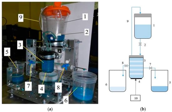
Figure 1.
Microparticles separation setup photo (a), and hydro-electrical scheme of the experimental set-up (b): 1—container of the microparticles in biological suspension; 2—adjustable inlet valve; 3—CFC (Ø 41 × Ø45 × 72 mm) of the acoustic separator; 4—DSPTB of the acoustic separator; 5—phase of the suspension enriched in microparticles; 6—purified phase of the suspension; 7—outlet valve of the phase of the suspension enriched in microparticles; 8—outlet valve of the purified phase of the suspension; 9—air escape valve; 10—controller of the disk-shaped piezo transducer-bimorph.

Table 1.
Technical data of DSPTB type 7BB-35-3.
During the experiment, the actuator was powered by a harmonic electrical signal in the frequency range of 1 to 25 kHz, with a maximum control voltage amplitude of 45 V. According to formula (5), the electric actuator power varied depending on the frequency and voltage of the control signal, and did not exceed 7 W:
where C is the electrical capacity of the actuator, F; U is the amplitude of control voltage, V; and f0 is the frequency of control signal, Hz.
P = π C U2 f0,
Equation (5) shows that the power of the piezoelectric transducer is highly dependent on the oscillation frequency (directly proportional), and correlates with the generated acoustic power in the suspension. In this case, the purpose of the microparticle separation process at lower frequencies is to minimize the acoustic field intensity in the suspension, which is important for the viability of the biological particles.
When the control valve is opened in container 1, shown in Figure 1, the continuous suspension with microparticle flow enters the chamber of the acoustic separator through adjustable inlet valve 2 [31]. The acoustic separator is composed of CFC 3 and DSPTB 4, attached to the bottom of the container, where, under the sonification of AWs, the suspension with microparticle drift in the CFC volume and the suspension enriched in microparticles accumulate in the nodal zones of the CFC walls, resonating on eigen frequency. Then, the suspension enriched in microparticles passes through the hole in the resonating CFC and flows from the nodal zones through outlet valve 7 to container 5. The purified from microparticles phase of the biological suspension from resonating CFC’s anti-nodal zones through the outlet valve 8 flows to container 6. The transfer of the different suspension phases is accomplished by laminar flow into separate containers, without causing streaming in the acoustically treated suspension. Valve 9 allows for air escape.
The integration of AWs into acoustofluidic devices has a positive impact on particle separation, especially for biomedical applications. The separation of microparticles from the suspension depends on their size, density and compressibility. Such separation process techniques have many advantages over centrifugal sedimentation or separation in microchannels, such as portability, low cost, small size and fast timing, which ensure reagent reduction, simple use and precise control. Due to the DSPTB, an excited continuous AW field forms a flow of suspension with microparticles, as well as mechanical vibrations of the CFC with suspension, which evoke the resonating modes of the CFC wall vibrations. Depending on the excitation frequency, the resonant eigenmodes are characterized by nodal and anti-nodal areas at certain distances along the container wall. When analyzing the effect of AWs on the suspension with microparticles volume, we noticed that the microparticles accumulated in certain areas of this volume where the zones of the CFC eigenmode nodes settled down. As the pressure of the suspension flow is minimized in nodal areas of the CFC, and maximized in anti-nodal areas, the suspension enriched by microparticles precipitates in low-pressure or nodal areas, and the suspension purified from microparticles precipitates in high-pressure or anti-nodal areas. The forces generated in this periodic pressure oscillation are used to separate microparticles and cells.
3. Results
3.1. Simulation Results
Because the DSPTB was mounted on the bottom of the CFC, it propagated acoustic fluid pressure and also excited vibration of CFC. As shown in Figure 2a, mechanical vibration activated a deformable plastic CFC, triggering a corresponding field of acoustic pressure. At a frequency of f0 = 13.8 kHz along the longitudinal axis of the CFC, the five nodal zones were formed, which indicated that the CFC was resonating on the fourth eigenmode. During the separation of microparticles in the field of AWs, they propagated to low acoustic pressure level zones. This physical phenomenon has been applied to the separation of microparticles.
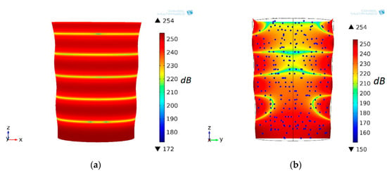
Figure 2.
Conical fluid container resonating on fourth eigenmode and sound pressure level (dB) (a), and (b) microparticle positions in section (xz plane) at time t = 0 s at f0 = 13.8 kHz excitation frequency of the disk-shaped piezo transducer-bimorph.
At the initial time t = 0 s, the suspension microparticles were evenly distributed in the CFC volume. The distribution of the acoustic pressure field level in the CFC volume, as shown in Figure 2b, was as follows: the three upper zones with a low pressure level were perpendicular to the flow of fluid along the longitudinal axis, and the two lower zones were not. The position of the particles in the field of acoustic pressure at t = 12 s, and their trajectories are provided in Figure 3a. The microparticles “cling” to the inner surface of the CFC wall in eigenmode nodal zones.
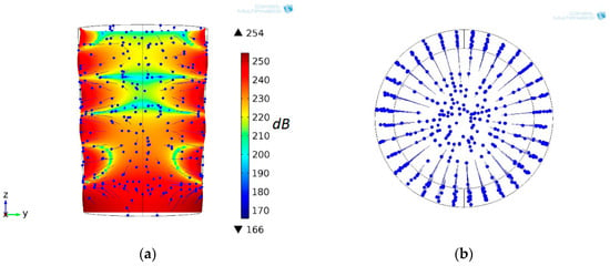
Figure 3.
CFC resonating on fourth eigenmode and sound pressure level (dB), field section (yz plane) and positions of the microparticles at time t = 12 s and their motion trajectories in the axial plane (a) and the cross-sectional plane (b) at f0 = 13.8 kHz excitation frequency of DSPTB.
As a result of acoustic effects, the microparticle movement was vertical near the anti-node, horizontal at the node, and inclined in between. Figure 3b shows the microparticles’ trajectories in the cross-sectional plane, observed from the top of the conical fluid container.
3.2. Experimental Results
In order to align the experimental results with the simulation results, the zeolite microparticles (made by Sigma-Aldrich, 3050 Spruce street, Saint Louis, MO 63103, USA, with microparticle dimensions 0.5–15 µm.) were mixed in an artificial plasma (90% water and 10% glycerol) with a viscosity of 1.3–1.7 mPa s, which coincides with the viscosity of the blood plasma. Zeolite, the active ingredient, is micronized to the size of a red blood cell. This means that the particles of zeolite are so fine that they can actually pass in between the cells. Zeolite was chosen because the experiment with the blood would be complicated due to the rapidly changing properties of red blood cells in the blood. Standard guidelines for handling blood samples indicate that plasma or serum should be separated from the cells as soon as possible (20–30 min) after the clot formation is complete, so as to avoid clot-induced changes in the serum concentrations of the analytic liquid caused by coagulation. The agglutination of red blood cells can occur within a few minutes after finding blood outside the body. To assess the separation process of microparticles in suspension, and determine the eigenmodes of the DSPTB and CFC body, an experimental setup with a Polytec 3D scanning vibrometer (Type PSV-500-3D-HV, Polytec GmbH, Waldbronn, Germany) was developed (Figure 4).
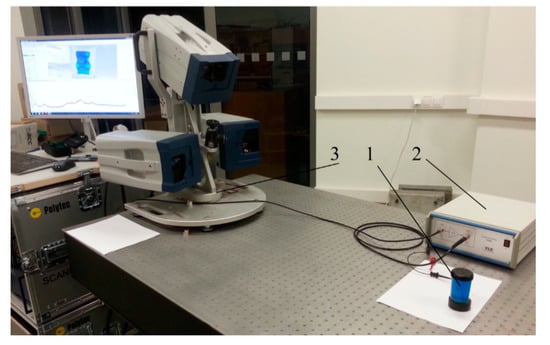
Figure 4.
Experimental setup: 1—an experimental object CFC; 2—liner amplifier P200 (FLC Electronics AB, Partille, Sweden); 3—3D scanning vibrometer PSV-500-3D-HV (Polytec GmbH, Waldbronn, Germany).
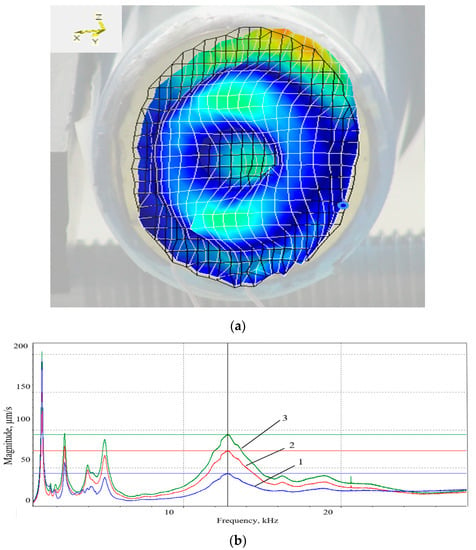
Figure 5.
Fourth eigenmode of the DSPTB at an operational frequency of f0 = 13.5 kHz (a), and frequency response (b) in three directions: 1—Z; 2—X; 3—Y.
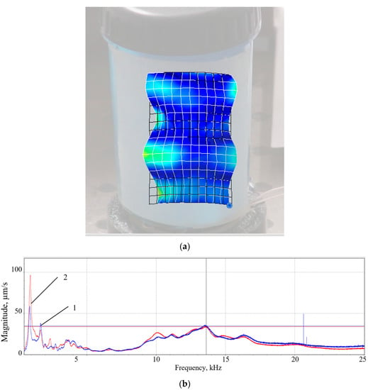
Figure 6.
Fourth eigenmode of the CFC at an operational frequency of 13.5 kHz (a), and frequency response (b) in two directions: 1—Z; 2—X.
The numerical values of the vibrating deflection shapes of the fourth eigenmode (Figure 3), as well as the frequency averaged spectrum of the DSPTB (Figure 5a,b) and of the CFC (Figure 6a,b), show that the DSPTB and the CFC vibration resonances are expressed at the near excitation frequency of f0 = 13.5 kHz. For this fourth eigenmode, the bandwidth of the resonance curves in the three coordinate directions was larger than for the lower eigenmodes. When switching to a higher mode, the number of microparticle concentration zones increased; however, the acoustic pressure no longer had such a high value. An agreement between model and data, which is characterized by almost the same excitation frequency (AWs at f0 = 13.5 kHz for the model and AWs at f0 = 13.8 kHz for the data) and the same number of fourth mode oscillations of the plastic conical fluid container wall, expressed by the four zones of microparticle accumulation, is presented in Figure 7.
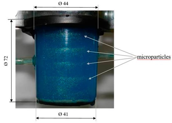
Figure 7.
Experimental arrangement of nodal zones with suspension enriched in microparticles under the influence of AWs at f0 = 13.5 kHz frequency.
To determine the effectiveness of the microparticle separation in biological suspension, two separate samples were examined under a microscope (Figure 8). A sample of the suspension purified from the microparticle phase (Figure 8a) has been taken from container 6 (Figure 1), and a sample of the suspension enriched in microparticle phase (Figure 8b) has been taken from container 5 (Figure 1).
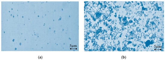
Figure 8.
Microscopic view of the suspension samples: (a) purified from microparticles; and (b) enriched in microparticles, obtained using a commercial software package (NIS-Elements AR, Nikon, Japan) to construct 2D microparticle images from the video signals, recorded with the Nikon Eclipse LV series microscope and PixeLINK PL-A662 camera.
Figure 8 depicts a comparison of the two samples of suspension from different clusters of purified and enriched microparticles, taken from the nodal and anti-nodal CFC zones vibrating on the fourth eigenmode. The areas of the microscopic views, acquired from video signals, are equal in both images, but the distribution density of the particles is different. A commercial software package (NIS-Elements AR, Nikon, Japan) has been used to construct 2D microparticle images from the video signals, recorded with the Nikon Eclipse LV series microscope and PixeLINK PL-A662 camera. The 75% separation rate is related to both modeling and experimentation at a time interval of 12 s.
The AWs’ integration into acoustofluidic devices had a positive impact on microparticle separation, especially for biomedical applications. The microparticle separation in suspension by AWs depended on their size, density and compressibility. The continuous field of AWs generated by an acoustic resonator formed a distribution of the minimum and maximum pressure regions, called pressure nodes and anti-nodes, respectively, in the fluid domain. The forces generated in this periodic pressure fluctuation were used to separate microparticles and cells.
4. Discussion
The method of acoustically excited microparticle continuous separation in a CFC, whose eigenmodes are excited by DSPTB, was proposed. The microparticles in biological suspension were taken to act as a substitute for red blood cells [32], and demonstrate the validity of the proposed separation technology by experiment. The correct solution for the combined acoustically excited fluid–structure interaction is shown in Figure 2 and Figure 3, wherein the vibrating CFC wall deflection shapes in the fourth eigenmode are shown. Standard guidelines for handling microparticles in biological suspension suggest that they should be processed as soon as possible (20–30 min), before the formation of clots, to avoid structural changes to the suspension [33]. As the microparticle separation process takes place via the excitation of the piezoelectric actuator and the container in higher bending oscillation modes (frequency about 13.5 kHz), this allows, to a certain extent, the generation of a sufficiently high intensity acoustic field, without a streaming effect, in the suspension. However, experiments have shown that at the higher amplitudes of oscillation of the piezoelectric actuator, a turbulent phenomenon occurs in the suspension, which, due to the resulting fluid streaming, begins to stir the fluid throughout the container volume, thus interfering with the acoustic standing wave effect on the suspension.
We showed experimentally and theoretically (Figure 7) that the 12-s period, during which an alignment of microparticles in the nodal zones of the vibrating CFC inner surface, could be considered very short vis-à-vis other known methods of microparticle separation [34]. The separation rate of purified/enriched microparticles (Figure 8a,b) was about 75%, compared to the original sample at a time interval of 12 s. Obviously, the separation rate increases with the time of exposure of the fluid to acoustic vibrations, and is similar to the prediction of the numerical model. The matching of simulated (f0 = 13.8 kHz) and experimentally obtained (f0 = 13.5 kHz) sonic excitation frequencies, as well as the coincidence of the microparticle concentration zone locations in both simulation and experimentation cases, proves that the numerical model imitates the real microparticle separation process. The separation time of microparticles increases with an increase in suspension volume and viscosity.
The theoretical and experimental results of the microparticle separator research show that, in the frequency range from 10 kHz to 16 kHz, fourth mode bending oscillations with a maximum of about 13.5 kHz are excited in both the piezo transducer and the CFC wall. Within this frequency range, the piezo transducer generates intense acoustic radiation pressure in the suspension, which pushes the suspension microparticles towards the nodal areas of the resonating container wall, while the liquid suspension phase collects at the intensively vibrating anti-nodal areas of the container wall. In the frequency range of 800 Hz to 5 kHz, the lower resonant oscillation modes of the piezo transducer are also excited, but they generate a more intensive streaming of the suspension than acoustic radiation pressure. Therefore, no separation of microparticles was achieved within this frequency range. Experiments have shown that increasing the amplitude of the oscillation at 13.5 kHz accelerates the separation process, but above a certain level, streaming becomes dominant, which disrupts the separated suspension phases. Analogous to the results presented in [35,36], we numerically simulated the distribution of red blood cell microparticles, in the acoustic pressure field level in the conical fluid container’s volume, at the initial time t = 0 s in the three upper zones with a low pressure level, which zones are perpendicular to the flow of fluid along the longitudinal axis, and also in the two lower zones which are not perpendicular as shown in Figure 2b. In Figure 3a, the positions of the particles in the field of acoustic pressure at t = 12 s, and their trajectories, are provided (all particles have the same diameter of 8 μm) where the microparticles “cling” to the inner surface of the CFC wall in the eigenmode nodal zones. As a result of acoustic effects, the microparticle movement was vertical near the anti-node, horizontal at the node, and inclined in between. During the experiment, the piezoelectric actuator was excited by an electrical signal with frequency of 13.5 kHz, the voltage amplitude of which was varied from 0 to 70 V. During the study it was observed that the process of microparticle separation begins when a voltage of 30 V is reached, and further increasing the voltage to 50 V leads to the occurrence of a turbulent phenomenon, which, due to the resulting fluid streaming, begins to stir the fluid throughout the container volume, thus interfering with the acoustic standing wave effect on the suspension. As a result of the research, the innovative piezoelectric microparticle separation device was developed.
5. Conclusions
A straightforward method for the separation of biological microparticles in suspension was proposed. A finite element model using COMSOL Multiphysics software was implemented for the simulation of the sonification process with acoustic pressure waves in a plastic conical fluid container excited by DSPTB. Experimental fluid flow studies, using 3D scanning technology, have validated the mathematical model, and found a less than 2% discrepancy between the modeled 13.8 kHz fourth eigenmode frequency, and the experimentally measured 13.5 kHz fourth eigenmode frequency. For the given volume of suspension, the microparticle concentration takes place (over 10–12 s) in the nodal zones, as well as in the purified fluid in the anti-nodal zones on the inner surface of the resonating conical fluid container. The separation process with AW devices has many advantages, such as portability, high accuracy and sensitivity, low cost, simple use and precise control, compared to conventional methods.
Author Contributions
V.O. initiated and supervised the development of the actuator and wrote the paper, R.G. and S.M. performed the numerical simulation, V.J., I.G. and L.K. developed experimental set-up design, assembly and integration of the prototype. All authors have read and agreed to the published version of the manuscript.
Funding
According to the supported activity No. 01.2.2- LMT-K-718 under the project No. DOTSUT-234.
Acknowledgments
This research was funded by the European Regional Development.
Conflicts of Interest
The authors declare no conflict of interes.
References
- Gosse, C.; Croquette, V. Magnetic tweezers: Micromanipulation and force measurement at the molecular level. Biophys. J. 2002, 82, 3314–3329. [Google Scholar] [CrossRef]
- Murray, C.; Pao, E.; Tseng, P.; Aftab, S.; Kulkarni, R.; Rettig, M.; Di Carlo, D. Quantitative magnetic separation of particles and cells using gradient magnetic ratcheting. Small 2016, 12, 1891–1899. [Google Scholar] [CrossRef]
- Ding, X.; Lin, S.-C.S.; Kiraly, B.; Yue, H.; Li, S.; Chiang, I.-K.; Shi, J.; Benkovic, S.-J.; Huang, T.-J. On-chip manipulation of single microparticles, cells, and organisms using surface acoustic waves. Proc. Nat. Acad. Sci. USA 2012, 109, 11105–11109. [Google Scholar] [CrossRef] [PubMed]
- Ozcelik, A.; Rufo, J.; Guo, F.; Gu, Y.; Li, P.; Lata, J.; Huang, T.-J. Acoustic tweezers for the life sciences. Nat. Methods 2018, 15, 1021–1028. [Google Scholar] [CrossRef] [PubMed]
- Wu, M.; Ozcelik, A.; Rufo, J.; Wang, Z.; Fang, R.; Huang, T.-J. Acoustofluidic separation of cells and particles. Microsyst. Nanoeng. 2019, 5, 32. [Google Scholar] [CrossRef] [PubMed]
- Courtney, C.R.P.; Drinkwater, B.W.; Demore, C.E.M.; Cohran, S.; Grinenko, A. Dexterous manipulation of microparticles using Bessel-function acoustic pressure fields. Appl. Phys. Lett. 2013, 102, 5. [Google Scholar] [CrossRef]
- Whitehill, J.; Neild, A.; Wah, N.T.; Stokes, M. Collection of suspended particles in a drop using low frequency vibration. Appl. Phys. Lett. 2010, 96, 3. [Google Scholar] [CrossRef]
- Oberti, S.; Neild, A.; Quach, R.; Dual, J. The use of acoustic radiation forces to position particles within fluid droplets. Ultrasonics 2010, 49, 47–52. [Google Scholar] [CrossRef]
- Nam, J.; Lee, Y.; Shin, S. Size-dependent microparticles separation through standing surface acoustic waves. Microfluid Nanofluidics 2011, 11, 317–326. [Google Scholar] [CrossRef]
- Park, K.; Park, J.; Jung, J.H.; Destgeer, G.; Ahmed, H.; Sung, H.J. In-droplet microparticle separation using travelling surface acoustic wave. Biomicrofluidics 2017, 11, 64112. [Google Scholar] [CrossRef]
- Rogers, P.; Gralinski, I.; Galtry, C.; Neild, A. Selective particle and cell clustering at air–liquid interfaces within ultrasonic microfluidic systems. Microfluid. Nanofluidics 2013, 14, 469–477. [Google Scholar] [CrossRef]
- Kanazaki, T.; Okada, T. Two-Dimensional particle separation in coupled acoustic-gravity-flow field vertically by composition and laterally by size. Anal. Chem. 2012, 84, 10750–10755. [Google Scholar] [CrossRef]
- Soliman, A.M.; Eldosoky, M.A.; Taha, T.E. The Separation of Blood Components Using Standing Surface Acoustic Waves (SSAWs) Microfluidic Devices: Analysis and Simulation. Bioengineering 2017, 2, 28. [Google Scholar] [CrossRef] [PubMed]
- Mishra, P.; Martyn, H.; Glynne-Jones, P. Deformation of red blood cells using acoustic radiation forces. Biomicrofluidics 2014, 8, 11. [Google Scholar] [CrossRef] [PubMed]
- Korobtsov, A.; Kotova, S.; Losevsky, N.; Mayorova, A.; Patlan, V.; Timchenko, E.; Lysov, N.; Zarubina, E. Optical tweezers technique for the study of red blood cells deformation ability. Laser Phys. 2012, 22, 1265. [Google Scholar] [CrossRef]
- Lenshof, A.; Magnusson, C.; Laurell, T. Acoustofluidics 8: Applications of acoustophoresis in continuous flow microsystems. Lab Chip 2012, 12, 1210. [Google Scholar] [CrossRef]
- Wiklund, M. Acoustofluidic 12: Biocompatibility and cell viability in microfluidic acoustic resonators. Lab Chip 2012, 12, 2018–2028. [Google Scholar] [CrossRef]
- Bazou, D.; Kearney, R.; Mansergh, F.; Bourdon, C.; Farrar, J.; Wride, M. Gene expression analysis of mouse embrionic stem cells following levitation in an ultrasound standing wave trap. Ultrasound Med. Biol. 2011, 37, 321–330. [Google Scholar] [CrossRef]
- Zoueshtiagh, F.; Thomas, P.-J.; Thomy, V.; Merlen, A. Micrometric granular ripple patterns in a capillary tube. Phys. Rev. Lett. 2008, 100, 54501. [Google Scholar] [CrossRef]
- Lerche, D.; Sobisch, T. Consolidation of concentrated dispersions of nano- and microparticles determined by analytical centrifugation. Powder Technol. 2007, 16, 46–49. [Google Scholar] [CrossRef]
- Dijkshoorn, J.P.; Schutyser, M.A.I.; Wagterveld, R.-M.; Schroën, C.-G.-P.-H.; Boom, R.M. A comparison of microfiltration and inertia-based microfluidics for large scale suspension separation. Sep. Purif. Technol. 2017, 173, 86–92. [Google Scholar] [CrossRef]
- Saxena, A.; Bijay, P.; Tripathi, B.P.; Kumar, M.; Shahi, V.K. Membrane-based techniques for the separation and purification of proteins: An overview. Adv. Colloid Interface Sci. 2009, 145, 1–22. [Google Scholar] [CrossRef] [PubMed]
- Devendran, C.; Carthew, J.; Frith, J.E.; Neild, A. Cell Adhesion, Morphology, and Metabolism Variation via Acoustic Exposure within Microfluidic Cell Handling Systems. Adv. Sci. 2019, 6, 1902326. [Google Scholar] [CrossRef] [PubMed]
- Belling, J.N.; Heidenreich, L.K.; Tian, Z.; Mendoza, A.M.; Chiou, T.T.; Gong, Y.; Chen, N.Y.; Young, T.D.; Wattanatorn, N.; Park, J.H.; et al. Acoustofluidic sonoporation for gene delivery to human hematopoietic stem and progenitor cells. Proc. Natl. Acad. Sci. USA 2020, 117, 10976–10982. [Google Scholar] [CrossRef] [PubMed]
- Collins, D.J.; Morahan, B.; Garcia-Bustos, J.; Doerig, C.; Plebanski, M.; Neild, A. Two-dimensional single-cell patterning with one cell per well driven by surface acoustic waves. Nat. Commun. 2015, 6, 8686. [Google Scholar] [CrossRef]
- Mutafopulos, K.; Spink, P.; Lofstrom, C.D.; Lu, P.J.; Lu, H.; Sharpe, J.C.; Franke, T.; Weitz, D.A. Traveling surface acoustic wave (TSAW) microfluidic fluorescence activated cell sorter (μFACS). Lab Chip 2019, 14, 2435–2443. [Google Scholar] [CrossRef]
- Link, A.; Franke, T. Acoustic erythrocytometer for mechanically probing cell viscoelasticity. Lab Chip 2020, 20, 1991–1998. [Google Scholar] [CrossRef]
- Ostasevicius, V.; Jurenas, V.; Golinka, E.; Gaidys, R.; Aleksa, A. Separation of microparticles from suspension utilizing ultrasonic standing waves in a piezoelectric cylinder actuator. Actuators 2018, 7, 14. [Google Scholar] [CrossRef]
- Settnes, M.; Bruus, H. Forces acting on a small particle in an acoustical field in a viscous fluid. Phys. Rev. E 2012, 85, 16327. [Google Scholar] [CrossRef]
- Gor’kov, L.P. On the forces acting on a small particle in an acoustical field in an ideal fluid. Sov. Phys. Dokl. 1962, 6, 773. [Google Scholar]
- Ostasevicius, V.; Jurenas, V.; Gaidys, R.; Kizauskiene, L. Acoustic Suspension Separation Device. LT Patent Unpublished Patent. 2021. [Google Scholar]
- Otterstedt, J.E.; Brandreth, D.A. Small Particles Technology; Springer: New York, NY, USA, 2010; p. 524. [Google Scholar]
- Turchiano, M.; Nguyen, C.; Fierman, A.; Lifshitz, M.; Convit, A. Impact of blood sample collection and processing methods on glucose levels in community outreach studies. J. Environ. Public Health 2013, 2013, 256151. [Google Scholar] [CrossRef] [PubMed]
- Stegmayr, B.G. A survey of blood purification techniques. Transfus. Apheresis Sci. 2005, 32, 209–220. [Google Scholar] [CrossRef] [PubMed]
- Muller, P.B.; Barnkob, R.; Jensen, M.J.H.; Bruus, H. A numerical study of microparticle acoustophoresis driven by acoustic radiation forces and streaming-induced drag forces. Lab Chip 2012, 22, 4617–4627. [Google Scholar] [CrossRef] [PubMed]
- Devendran, C.; Albrecht, T.; Brenker, J.; Alan, T.; Neild, A. The importance of travelling wave components in standing surface acoustic wave (SSAW) systems. Lab Chip 2016, 16, 3756–3766. [Google Scholar] [CrossRef] [PubMed]
© 2020 by the authors. Licensee MDPI, Basel, Switzerland. This article is an open access article distributed under the terms and conditions of the Creative Commons Attribution (CC BY) license (http://creativecommons.org/licenses/by/4.0/).