Abstract
The output feedback signal of the electro-hydraulic valve system (EHVS) affects the activation of its right or left envelope function; thus, even weak measurement noise can cause high-frequency switching between the two envelope functions, leading to chattering in the control input. Consequently, feedforward and feedback controllers in a cascaded configuration generate undesirable chattering in the output signal. We propose a practical and reliable control approach for an EHVS actuated by a proportional control valve. The proposed controller has a parallel structure comprising an inverse generalized Prandtl–Ishlinskii (P–I) model-based feedforward controller, with both hydraulic dead-zone and flow saturation limits, for compensating asymmetric hysteretic behavior. Further, the proposed controller comprises a robust proportional-integral-derivative (PID) feedback controller for achieving robustness against disturbances and noises. The proposed parallel structure is independent of the output feedback of the EHVS. Moreover, the proposed robust PID feedback controller guarantees EHVS stability by precisely selecting the cutoff frequency for the sensitivity and complementary sensitivity functions based on the amplitude spectrum of the inverse-model-based feedforward compensation error. The results verify the high reliability of the proposed EHVS control scheme for the precise control of an EHVS actuated by a proportional control valve in practice.
1. Introduction
Electro-hydraulic valve systems (EHVSs) have been extensively applied to heavy industrial machinery, robot manipulators, tunnel boring machines, mobile systems, and different machine tools, owing to their characteristics such as high power-to-weight ratio, appropriate stiffness, self-cooling, rapid response, and high positioning ability. However, an EHVS with proportional control valves for adjusting the flow rate and direction usually suffers from strong nonlinearities, such as asymmetric hysteresis with non-differentiable, non-memoryless, multi-value mapping, hydraulic dead-zone, and flow saturation limits. These nonlinearities substantially degrade the tracking accuracy of the EHVS and may lead to instabilities when implementing closed-loop systems [1,2,3,4,5,6,7]. Therefore, many control methods have been proposed to mitigate the effects of nonlinearities in EHVSs [1,2,3,8].
Most studies have focused on the feedforward control using an inverse hysteresis model to linearize the hysteretic input–output characteristics of a class of highly nonlinear EHVSs. In these methods, an appropriate hysteresis model is established to precisely predict the complex nonlinear behaviors of the system. Then, its inverse model is derived analytically or numerically for performing feedforward control. Various hysteresis models including the Preisach, Krasnoselskii–Pokrovskii, and generalized Prandtl–Ishlinskii (P–I) models have been reported in the past [4]. Unlike the Preisach and Krasnoselskii–Pokrovskii models, the generalized P–I model, which we adopted in this study, provides the essential analytical inversion for efficient hysteretic nonlinearity compensation [9]. Furthermore, the generalized P–I model allows mathematical descriptions of both symmetric and asymmetric hysteresis phenomena with dead zone and output saturation, thus being suitable for EHVSs. We have recently devised the direct identification of the generalized P–I model inversion to facilitate real-time cancellation of asymmetric hysteresis nonlinearities during feedforward compensation [10]. Nevertheless, feedforward control using an inverse hysteresis model is not robust, especially under low-frequency disturbances and high-frequency noise that are inevitable in an EHVS [3,11]. Thus, feedforward control is usually combined with feedback control to increase the bandwidth, improve tracking performance, and reject the influence of disturbances and noise in the closed-loop control system [11].
Various challenges and limitations of existing closed-loop EHVS control methods remain to be addressed. The inverse generalized P–I model as a feedforward controller and the proportional-integral-derivative (PID) controller as a feedback controller can be combined in different structures such as cascade or parallel connection [12,13]. Although feedforward control using the inverse generalized P–I model can be combined with proportional–integral–derivative (PID) feedback control in either cascade or parallel configuration, a cascade structure produces undesired chatter in the output signal. Despite the severity of this problem for EHVS applications, it has not been adequately addressed. In fact, the activation of the right or left envelope function in the inverse generalized P–I model is directly affected by the EHVS output feedback signal, and even weak measurement noise can thus cause high-frequency switching between the two envelope functions, resulting in control input chattering. The cascade implementation of the inverse hysteresis model may substantially aggravate the reference tracking accuracy of the EHVS closed-loop control, as detailed and experimentally demonstrated in this study. We adopt a robust PID controller as the feedback control structure of an EHVS actuated by a proportional control valve to increase the robustness against disturbances and noise. The control parameters are determined according to the controller tuning strategy proposed in Kim et al. [14]. To successfully apply this tuning strategy, two stable frequency-dependent weighting functions should be designed for the sensitivity and complementary sensitivity functions, which are associated with the performance and robustness of the closed-loop EHVS. However, a systematic methodology for determining the critical cutoff frequency of the weighting functions has not been fully developed.
The main contributions of this paper can be summarized as follows. First, we propose a method to determine the cutoff frequency of the weighting functions for the closed-loop robust PID control of an EHVS actuated by a proportional control valve. The cutoff frequency is determined by examining the amplitude spectrum of the measured feedforward compensation error generated by uncertainties in the inverse generalized P–I model. The compensation error can be handled as an exogenous periodic disturbance to the linear dynamics while excluding nonlinearities [15]. Second, we evaluate the practical necessity of adopting the parallel implementation of the feedforward controller using the inverse generalized P–I model to an EHVS compensated by a robust PID controller in the closed-loop system. In addition, we experimentally demonstrate that the feedforward control using the inverse hysteresis model plus robust PID feedback control in cascade connection does not provide sufficient robustness against output EHVS noise. These experimental and analytical results justify the implementation of the feedforward and feedback controllers in a parallel structure for the former to be independent from the EHVS output feedback signal. The proposed control scheme allows the EHVS output to precisely track a desired trajectory and increases the robustness of the EHVS actuated by the proportional control valve, as verified via experiments.
The remainder of this paper is organized as follows—Section 2 briefly reviews the direct development of the inverse generalized P–I model for hysteretic systems and then presents the experimental compensation of hysteretic nonlinearities in an EHVS using the corresponding feedforward controller. In Section 3, the linear dynamic model of the EHVS, assuming its hysteretic behavior is compensated by feedforward cancellation using the inverse generalized P–I model, is derived using time-domain identification via meta-heuristic optimization, namely cyclic-network-topology particle swarm optimization (CNT-PSO) [16] developed by one of the authors of the present paper. Section 4 details the method to determine the cutoff frequency of the weighting functions and presents the design results of the robust PID controller for the EHVS. Section 5 details the parallel implementation of the feedforward control using the inverse generalized P–I model combined with the robust PID controller in a closed loop. In addition, the experimental comparison of the tracking and robustness performances between the cascade and parallel configurations of the inverse hysteresis model and robust PID controller are reported. Finally, some conclusions are presented in Section 6.
2. Feedforward Control for Nonlinearity Compensation
This section first reviews the inversion of a generalized P–I model. Then, it presents the procedure and experimental results of directly developing an inverse generalized P–I model [10] to precisely identify the known model parameters. Finally, we report the experimental validation and performance evaluation of hysteresis compensation achieved by the identified inverse generalized P–I model used as a feedforward controller.
2.1. Inverse Generalized P–I Model
The complex input–output characteristics of an asymmetric hysteresis with dead zone and output saturation of the nonlinear target system illustrated in Figure 1 should be linearized. To this end, it is critical to derive an exact inverse hysteresis model . We adopt a recently proposed method for direct construction of the inverse generalized P–I model [10] instead of analytically deriving the inversion from an estimated model . We briefly describe the discrete version of the inverse generalized P–I model below. The output of the inverse model is expressed as
with the classical play hysteresis operator being defined as
where play operators are considered, and are envelope functions, and and are finite sequences of thresholds and discrete weights, respectively, corresponding to the density function in the inverse model. Details of the derivation of this inverse model can be found in our previous study [10]. The uncertain model parameters, and , in the inverse threshold and density functions for can be identified directly from input–output measurements using CNT-PSO [16].
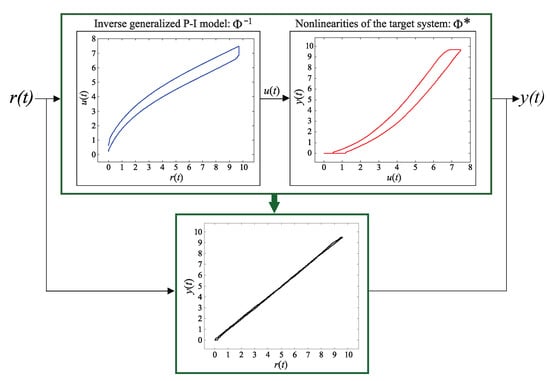
Figure 1.
Illustration of nonlinearity compensation by an inverse hysteresis model.
2.2. Parameter Identification and Experimental Validation
We conducted experiments on the EHVS actuated by a proportional control valve, as shown in Figure 2, to measure the output data when applying a triangle wave voltage input of frequency and amplitude for with sampling interval . The specifications of the experimental EHVS are listed in Table 1. Figure 3 shows the complex nonlinearities in the EHVS input–output characteristics, which indicate an asymmetric hysteresis with dead zone and output saturation between the input and measured output .
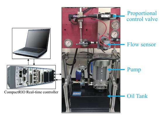
Figure 2.
Schematic diagram of the experimental setup of the electro-hydraulic valve system.

Table 1.
Specifications of experimental EHVS.
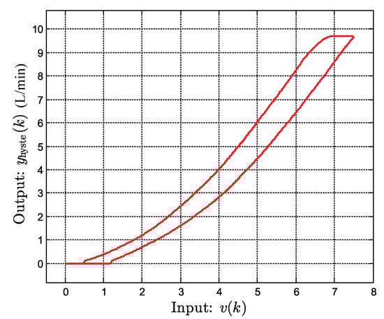
Figure 3.
Input-output relationship between the input and the measured output .
Let denote the real nonlinear behavior in Figure 3 of the EHVS in Figure 2. The unknown parameters of inverse generalized P–I model in (1) and (2) are directly estimated using the identification method in Reference [10]. Figure 4 illustrates the schematic diagram in our identification procedure for direct construction of . For identifying inverse model of the EHVS, the envelope, threshold, and density functions are given by
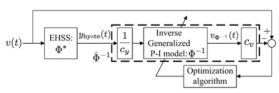
Figure 4.
Schematic diagram of the direct identification method of the inverse generalized P–I model .
Therefore, the design parameter vector to be identified is , where , , , and .
Let the sampled output of inverse model be represented by as shown in Figure 4. Then, we define the objective function as
because , where is a user-defined scaling factor. We select and in Figure 4 to be 10 for the available maximum values to be scaled to norm 1.
Finally, we use CNT-PSO [16] to solve optimization problem . The identification results of the unknown parameters in are summarized as follows:
The relation of input into the identified inverse model and the resulting output of (i.e., inverse hysteresis loop) is shown in Figure 5, where inverse model is given by (1) and (2) with estimated design parameters given in (7)–(10). We implement the identified inverse generalized P–I model, , as the feedforward controller shown in Figure 1 and verify the precision of the estimated model parameters. Figure 6 shows the compensation results when applying triangle wave input with frequency of and amplitude of to the EHVS compensated by (i.e., ).
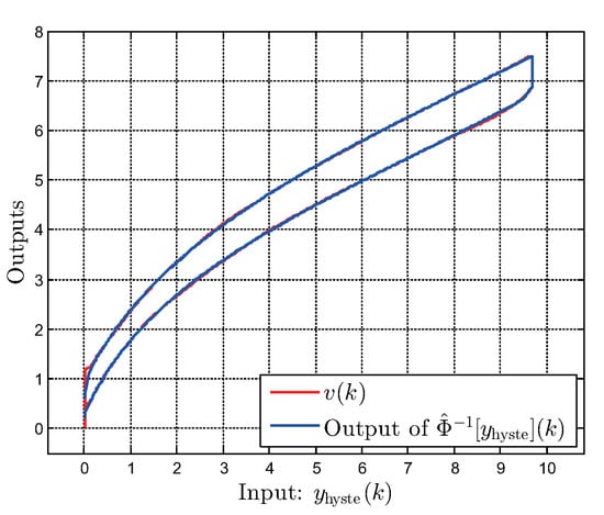
Figure 5.
Comparison of the responses of the directly identified inverse model with the measured nonlinearities.
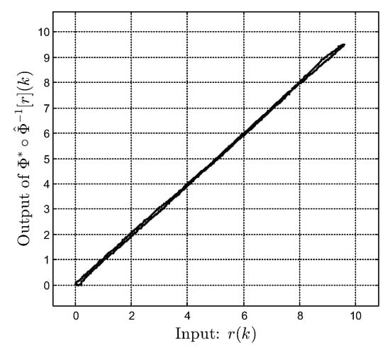
Figure 6.
Relationship between the input and the output of the inverse compensation .
However, the derived feedforward control lacks robustness, which is essential for the EHVS given the related low-frequency disturbances and high-frequency noise. Therefore, feedforward control should be combined with feedback control to increase robustness. In Section 3, we present the parameter identification of a linear dynamics model excluding nonlinear components to design the corresponding feedback controller.
3. Identification of EHVS Linear Dynamics Model
A linear dynamical system preceded by a hysteresis operator can be used to model an EHVS. Therefore, the dynamics compensated by approximate inverse hysteresis model with open-loop feedforward control can be treated as a linear system [15]. We derive the corresponding linear dynamics model based on time-domain identification using a set of input–output measurements obtained by injecting pseudo-random binary sequence (PRBS) into the feedforward-compensated EHVS (i.e., ) for at sampling interval s. Measured output signal and excitation signal are shown in Figure 7. The linear dynamics model can be expressed as a second-order transfer function:
where the design parameter vector to be identified is .
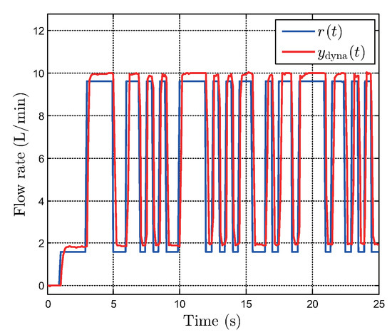
Figure 7.
Output of the EHVS combined with the inverse model excited by the PRBS signal .
We formulate the corresponding objective function as follows:
where is the sampled output of the second-order transfer function in (11). Note that uncertainties may exist not only in the linear dynamics model but also in the inverse hysteresis model presented in Section 2. Nevertheless, the discrepancy between the approximate inverse hysteresis model and the hysteretic behavior of the EHVS can be treated as an exogenous disturbance to the linear dynamics [15]. Therefore, to select a nominal model considering the linear model uncertainties, we performed experiments to collect output data over 10 repetitions using a pseudo-random binary sequence . For the input–output measurement data in each experiment, we solve the optimization problem in (12) using CNT-PSO [16] to determine the optimal .
Figure 8 shows the frequency responses of the 10 linear dynamics models identified, where the red line represents the response of the selected nominal model, , with parameter estimation . Figure 9 shows the identification results of the nominal model, where is the output of the nominal model with the parameters in .
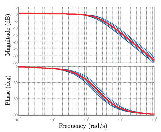
Figure 8.
Bode diagrams of the identified linear dynamics models where the red line corresponds to the nominal model.
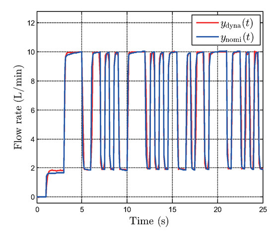
Figure 9.
Comparison of the measured output and the output of the identified nominal model.
To experimentally validate the nominal model , we applied a sinusoidal signal to the EHVS combined with the inverse hysteresis model for at sampling interval . Figure 10 shows the experimental validation results comparing the measured output and output of the nominal model with the parameters in . We adopt this model to design the feedback controller detailed in Section 4.
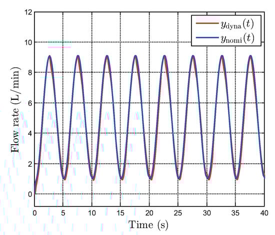
Figure 10.
Experimental validation of the nominal model.
4. EHVS Feedback Controller
We propose a technique to determine the cutoff frequency of the weighting functions by examining the amplitude spectrum of the feedforward compensation error, which comprises the harmonics of the input signal. Then, we design a robust PID controller satisfying the given specifications using the tuning method proposed by Kim et al. [14] to improve the EHVS robustness against disturbances and noise.
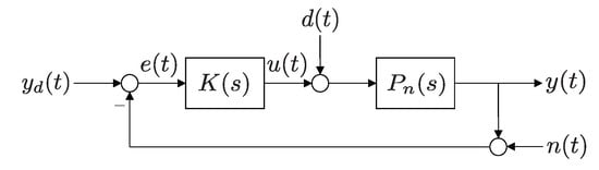
Figure 11.
Block diagram of the PID feedback control system.
Note that is the desired trajectory, is the error signal, is the control signal, is the controlled output, is the disturbance input, and is the sensor noise. In Figure 11, denotes the PID controller designed as follows:
where , , and are the proportional, integral, and derivative gains, respectively. Thus, the design parameter vector is .
The sensitivity function and complementary sensitivity function of the closed-loop system are respectively defined as
The robust performance criteria based on and are given by
where and represent stable frequency-dependent weighting functions. The weighting function has high gain at low frequencies to reject low-frequency disturbances, whereas the weighting function has high gain at high frequencies to mitigate sensor noise. We consider the following weighting functions:
where is the cutoff frequency, is a bound at high frequency, and is a bound at low frequency of weighting function , whereas and are the bounds at low and high frequencies of weighting function , respectively.
To obtain the cutoff frequency of the weighting functions, we adopt the following technique. First, we apply sinusoidal signal to the EHVS combined with the inverse hysteresis model for at sampling interval . Second, we obtain the fast Fourier transform of feedforward compensation error [], which is considered as an exogenous periodic disturbance, to obtain its spectrum. The amplitude spectrum of the error is shown in Figure 12 and comprises harmonics of sinusoidal signal . Third, we approximate the cutoff frequency of the weighting function as because the harmonics under are dominant when compared with other harmonics. In other words, low-frequency disturbances under influencing the closed-loop system can be rejected by the robust PID controller with weighting function using cutoff frequency of . Additionally, we set , , , and as bounds at low and high frequencies. Thus, the designed weighting functions for the sensitivity and complementary sensitivity functions are given by
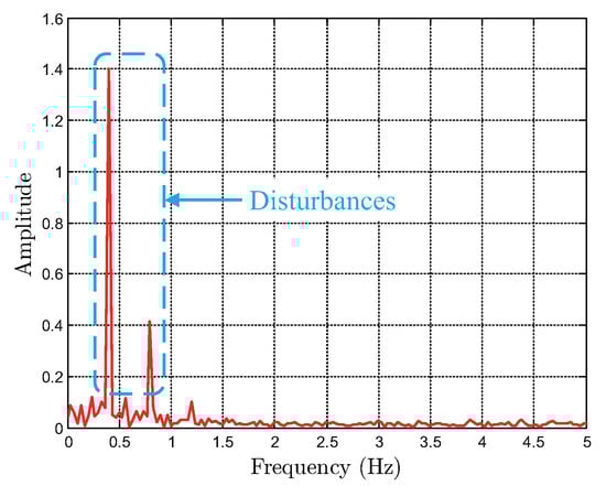
Figure 12.
Amplitude spectrum of the feedforward compensation error .
Let denote the closed-loop system consisting of nominal model and PID controller . The constrained optimization problem to find the optimal parameters can be formulated as follows:
subject to
where denotes the maximum real part of all the poles in the closed-loop system. The optimal parameters obtained from CNT-PSO [14] are , which guarantee and . Figure 13 shows the bode plots of sensitivity function and complementary sensitivity function , verifying that the given constraints are guaranteed.
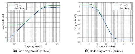
Figure 13.
Frequency responses of sensitivity and complementary sensitivity functions.
5. Feedforward Plus Feedback Controller and Experimental Validation
We experimentally verified the tracking performance and robustness of the inverse generalized P–I model plus robust PID controller in cascade and parallel connections. The experimental results demonstrate that the proposed method can improve the tracking performance and robustness of an EHVS actuated by a proportional control valve.
5.1. Tracking Performance Test
The inverse generalized P–I model as the feedforward controller and robust PID controller as the feedback controller can be integrated in cascade or parallel configuration, as shown in Figure 14 (see Remark 1 for details.). However, the feedforward plus feedback controller integrated in a cascade configuration, as shown in Figure 14a, cannot guarantee robustness against output noise. In fact, chatter is inevitable in cascaded control because the right and left envelope functions of the inverse generalized P–I model, which are dependent on the control signal contaminated by the output noise, can repeatedly switch by such noise in the EHVS. To demonstrate this problem experimentally, we applied desired flow rate , a triangle wave with frequency of and amplitude of , to the systems shown in Figure 14a,b for at sampling interval .
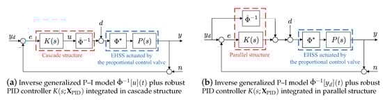
Figure 14.
Block diagrams of the feedforward plus feedback control system.
The tracking results of the cascade control system (Figure 14a) are shown in Figure 15b, where and are the desired and measured flow rates, respectively. The output of the inverse generalized P–I model, , is shown in Figure 15a. These experimental results demonstrate that the inverse hysteresis model in the cascade connection is susceptible to output noise. Figure 16a,b show the tracking results of the feedforward plus feedback control system integrated in parallel connection (Figure 14b) and the output of the inverse generalized P–I model, , respectively. These experimental results show that chattering can be eliminated because inverse hysteresis model in the parallel connection is independent of the output noise in the EHVS.
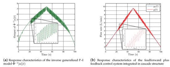
Figure 15.
Experimental results of the feedforward plus feedback control system integrated in cascade structure.
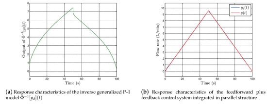
Figure 16.
Experimental results of the feedforward plus feedback control system integrated in parallel structure.
Remark 1.
The inversion-based feedforward controller has been used as a simple output tracking method for several applications. Although feedforward control has the advantage of fast response regardless of sensor measurements, it has a critical drawback in that an inversion-based feedforward input may adversely affect the output tracking performance, especially when modeling errors exist [17,18,19]. Therefore, the feedforward controller is generally combined with a feedback controller to achieve better output tracking performance; in such a case, the feedback controller should be designed to cope with not only unmodeled dynamics but also disturbances and noises. For example, Fan and Tan [18] recently proposed a control scheme for a class of hysteretic systems; in this scheme, a simple proportional-integral (PI) feedback controller was in series with an inverse P–I model-based feedforward controller, as shown in Figure 14a (cascade structure). However, the adopted PI feedback controller, which was in the cascade structure, cannot theoretically guarantee robustness against system uncertainties. Therefore, an additional disturbance observer should be designed and embedded inside the main PI feedback control loop, to reject lumped disturbances such as hysteresis modeling error and external disturbances. Furthermore, even if a robust feedback controller is implemented in such a cascade structure, robustness against output noises cannot be guaranteed; this can be confirmed based on Figure 15b. Moreover, Jung et al. [19] proposed a two-degree-of-freedom compensation system that uses a hysteresis model-based feedforward controller; in this system, the controller is placed in parallel with the forward path that contains the feedback controller, as shown in Figure 14b (parallel structure). However, Jung et al. also used only a naive feedback scheme using a PI controller. Thus, this scheme may not tackle noises, disturbances, and modeling errors. Compared to the approaches proposed in these recent studies, our approach theoretically guarantees practical robustness against model uncertainties as well as against external disturbances and noises.
5.2. Robustness Test
We experimentally evaluated the EHVS robustness against low-frequency disturbances and high-frequency noise using the proposed parallel control strategy. Figure 17 shows the responses obtained from the feedforward plus feedback control system in the parallel configuration shown in Figure 14b. The disturbance rejection results are shown in Figure 17a for step disturbance with magnitude and low-frequency components added at . Figure 17b shows the noise rejection results under Gaussian white noise and high-frequency components added at . These experimental results demonstrate that the proposed robust PID controller with the weighting function at cutoff frequency of can reject the influence of low-frequency disturbances and high-frequency noise.
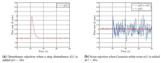
Figure 17.
Robustness validation of the feedforward plus feedback control system integrated in parallel structure.
6. Conclusions
We propose a feedforward controller using an inverse model to compensate for nonlinearities and a robust PID controller to enhance robustness against disturbances and noise for an EHVS actuated by a proportional control valve. Based on the amplitude spectrum of the feedforward compensation error, we propose a technique to both determine the cutoff frequency of the weighting functions and design a robust PID controller satisfying specifications. We experimentally demonstrate that the chatter phenomenon is caused by the cascaded inverse generalized P–I model and robust PID controller because the envelope functions are switched by output noise in the EHVS. Finally, the experimental results show that the chatter can be eliminated using the combined feedforward plus feedback controller in parallel because the inverse generalized P–I model as the feedforward controller in this structure is independent of the output noise in the EHVS, and the proposed robust PID controller can reject the influence of both low-frequency disturbances and high-frequency noise in the closed-loop control system.
Author Contributions
Conceptualization and methodology, Y.-R.K. and T.-H.K.; software and experiments, Y.-R.K.; validation and formal analysis, T.-H.K.; writing—original draft preparation, Y.-R.K.; writing—review and editing, T.-H.K.; funding acquisition, T.-H.K. All authors have read and agreed to the published version of the manuscript.
Funding
This research was supported by the Basic Science Research Program through the National Research Foundation (NRF) of Korea funded by the Ministry of Education (NRF-2016R1D1A1B03935288) and the Chung-Ang University research grant in 2018.
Conflicts of Interest
The authors declare no conflict of interest.
References
- Lee, I.-Y.; Oh, D.-H.; Ji, S.-W.; Yun, S.-N. Control of an overlap-type proportional directional control valve using input shaping filter. Mechatronics 2015, 29, 87–95. [Google Scholar] [CrossRef]
- Milić, V.; Šitum, Ž.; Essert, M. Robust H∞ position control synthesis of an electro-hydraulic servo system. ISA Trans. 2010, 49, 535–542. [Google Scholar] [CrossRef] [PubMed]
- Guo, K.; Wei, J.; Fang, J.; Feng, R.; Wang, X. Position tracking control of electro-hydraulic single-rod actuator based on an extended disturbance observer. Mechatronics 2015, 27, 47–56. [Google Scholar] [CrossRef]
- Gu, G.-Y.; Zhu, L.-M.; Su, C.-Y.; Ding, H.; Fatikow, S. Modeling and control of piezo-actuated nanopositioning stages: A survey. IEEE Trans. Autom. Sci. Eng. 2016, 13, 313–332. [Google Scholar] [CrossRef]
- Yang, Z.; He, Z.; Li, D.; Yu, J.; Cui, X.; Zhao, Z. Direct drive servo valve based on magnetostrictive actuator: Multi-coupled modeling and its compound control strategy. Sen. Actuators Phys. 2015, 235, 119–130. [Google Scholar] [CrossRef]
- Taghizadeh, M.; Yarmohammadi, M.J. Development of a self-tuning PID controller on hydraulically actuated stewart platform stabilizer with base excitation. Int. J. Control. Autom. Syst. 2018, 16, 2990–2999. [Google Scholar] [CrossRef]
- Won, D.; Kim, W. Disturbance observer based backstepping for position control of electro-hydraulic systems. Int. J. Control. Autom. Syst. 2015, 13, 488–493. [Google Scholar] [CrossRef]
- Zhao, J.; Wang, J.; Wang, S. Fractional order control to the electro-hydraulic system in insulator fatigue test device. Mechatronics 2013, 23, 828–839. [Google Scholar] [CrossRef]
- Al Janaideh, M.; Rakheja, S.; Su, C.-Y. An analytical generalized Prandtl–Ishlinskii model inversion for hysteresis compensation in micropositioning control. IEEE/ASME Trans. Mechatron. 2011, 16, 734–744. [Google Scholar] [CrossRef]
- Ko, Y.-R.; Hwang, Y.; Chae, M.; Kim, T.-H. Direct identification of generalized Prandtl–Ishlinskii model inversion for asymmetric hysteresis compensation. ISA Trans. 2017, 70, 209–218. [Google Scholar] [CrossRef] [PubMed]
- Liu, Y.; Shan, J.; Gabbert, U. Feedback/feedforward control of hysteresis-compensated piezoelectric actuators for high-speed scanning applications. Smart Mater. Struct. 2014, 24, 015012. [Google Scholar] [CrossRef]
- El-Shaer, A.H.; Janaideh, M.A.; Krejci, P.; Tomizuka, M. Robust performance enhancement using disturbance observers for hysteresis compensation based on generalized Prandtl–Ishlinskii model. J. Dyn. Syst. Meas. Control. 2013, 135. [Google Scholar] [CrossRef]
- Sayyaadi, H.; Zakerzadeh, M.R. Position control of shape memory alloy actuator based on the generalized Prandtl–Ishlinskii inverse model. Mechatronics 2012, 22, 945–957. [Google Scholar] [CrossRef]
- Kim, T.-H.; Maruta, I.; Sugie, T. Robust PID controller tuning based on the constrained particle swarm optimization. Automatica 2008, 44, 1104–1110. [Google Scholar] [CrossRef]
- Esbrook, A.; Tan, X.; Khalil, H.K. Control of systems with hysteresis via servocompensation and its application to nanopositioning. IEEE Trans. Control. Syst. Technol. 2013, 21, 725–738. [Google Scholar] [CrossRef]
- Maruta, I.; Kim, T.-H.; Song, D.; Sugie, T. Synthesis of fixed-structure robust controllers using a constrained particle swarm optimizer with cyclic neighborhood topology. Expert Syst. Appl. 2013, 40, 3595–3605. [Google Scholar] [CrossRef]
- Devasia, S. Should model-based inverse inputs be used as feedforward under plant uncertainty? IEEE Trans. Autom. Control. 2002, 47, 1865–1871. [Google Scholar] [CrossRef]
- Fan, Y.; Tan, U.-X. Design of a feedforward-feedback controller for a piezoelectric-driven mechanism to achieve high-frequency nonperiodic motion tracking. IEEE/AMSE Trans. Mechatron. 2019, 24, 853–862. [Google Scholar] [CrossRef]
- Jung, S.; Choi, S.B.; Ko, Y.; Kim, J.; Lee, H. Pressure control of an electro-hydraulic actuated clutch via novel hysteresis model. Control. Eng. Pract. 2019, 91. [Google Scholar] [CrossRef]


© 2020 by the authors. Licensee MDPI, Basel, Switzerland. This article is an open access article distributed under the terms and conditions of the Creative Commons Attribution (CC BY) license (http://creativecommons.org/licenses/by/4.0/).