Article

Development of a Novel Latching-Type Electromagnetic Actuator for Applications in Minimally Invasive Surgery

Mechanical Engineering, University of Dundee, Dundee DD1 4HN, UK
*
Author to whom correspondence should be addressed.
Actuators 2020, 9(2), 41; https://doi.org/10.3390/act9020041
Submission received: 29 March 2020 / Revised: 18 May 2020 / Accepted: 19 May 2020 / Published: 22 May 2020

Abstract

:
Single-port laparoscopic surgery (SLS), which utilises one major incision, has become increasingly popular in the healthcare sector in recent years. However, this technique suffers from several problems particularly the inability of current SLS instruments to provide the optimum angulation that is required during SLS operations. In this paper, the development of a novel latching-type electromagnetic actuator is reported, which is aimed to enhance the function of SLS instruments. This new actuator is designed to be embedded at selected joints along SLS instruments to enable the surgeon to transform them from their straight and slender shape to an articulated posture. The developed electromagnetic actuator is comprised of electromagnetic coil elements, a solid magnetic shell, and a permanent magnet used to enhance the magnetic field interaction along the force generation path and also to provide the latching effect. In this investigation, electromagnetic finite element analyses were conducted to design and optimise the actuator’s electromagnetic circuit. In addition, the performance of the new actuator was numerically and experimentally determined when output magnetic forces and torques in excess of 9 N and 45 mNm, respectively together with an angulation of 30° were achieved under a short pulse of current supply to the magnetic circuit of the actuator.

1. Introduction

Single-port laparoscopic surgery (SLS) is a fairly new paradigm in minimally invasive surgery, which aims to improve cosmesis and reduce the complications associated with standard multiport laparoscopic approaches, such as port-site hernias, haematoma, and wound infection. However, several technical challenges still need to be addressed in the current SLS settings, especially in the area of instrumentation. Most of the current issues that impede the wider dissemination of SLS include the inadequate exposure of the surgical field, lack of assistants for organ retraction, instrument crowding due to limited angulation usually realised in a traditional laparoscopic approach by placing ports at desired distances on the abdominal wall, restricted range of movements, and difficult in-line work and vision [1]. These impeding factors could potentially increase the operative time of the procedures and have bearings on the safety of patients, especially during the learning curve of surgeons. In recent years, several technological advancements have been proposed to overcome some of the above issues. For example, specially designed ports to accommodate multiple instruments through a small incision [2], oblique viewing cameras with flexible tips [3], right-angled light cables for the cameras [4], and pre-bent instruments [5], are some of these advancements. However, some comparative studies have reported conflicting results in the application of, for example, pre-bent instruments, which were found inadequate by some surgical groups [6]. Therefore, enhancing the function of the surgical instruments with a new actuation technology to increase their adaptability and provide the optimum angulation required during SLS operations with a push of a button has become the most demanded improvement by surgeons [7]. In this activity, several designs have been attempted [8,9]. However, it has become obvious that miniaturisation of the proposed conventional actuation systems, such as pneumatic actuators and linear electric motors, to permit their insertion into a narrow surgical trocar, drastically reduces their output capability. In addition, multiple cables and tubes required by these actuators, which are embedded at various joints along SLS tools, would result in a bulky, heavy, and mechanically complex surgical system. Consequently, the current systems have not found their successful deployment in most SLS theatres. Instead, novel, compact, and lightweight actuation systems with adequate mechanical simplicity and robustness are essential if a real improvement is aimed at the function of SLS tools.
As a result of their simple fabrication and safe energy source, electromagnetic actuators have been proposed to enhance the function of some medical applications [10,11]. However, in recent years, several investigations have shown that electromagnetic actuators fail to generate efficient force outputs when they are miniaturised for minimal-space applications [12,13]. In addition, the force generation of electromagnetic actuators cannot be enhanced with a simple increase in the current supplied to the coil element, as problems such as the inevitable temperature rise could reduce the suitability of these actuators for medical applications.
In ordinary linear electromagnetic actuators, a plunger changes positions when the coil is energised whilst a retaining mechanical spring brings the plunger back when the coil is de-energised. The coil is supplied with a sustained current to generate a magnetic field that interacts with a magnetisable armature, causing it to move in a linear motion. However, despite the low force generation resulting in minimal-size applications, the coil must still be continually activated during actuation, which results in a dramatic temperature rise [14]. If a cooling-down system is introduced, the size of the actuator would significantly increase and sealing problems may arise. Hence, latching-type electromagnetic actuators were proposed to provide the locking mechanism, with the aid of a permanent magnet armature, after the required motion is achieved, which reduces energy consumption and heat generation problems [15]. However, most of the reported latching-type electromagnetic actuators have been developed for large-size, general purpose applications [16]. Details and analysis of the physical phenomena of electromagnetic actuators are well covered in the technical literature (see for example [17]).
The current investigation has been directed towards the development of a novel latching-type electromagnetic actuator, which is proposed to enhance the function of SLS instruments, particularly their ability to provide the optimum tool’s angle required in SLS environments. Specific requirements for SLS applications, including the output angle and torque in addition to a special central channel needed for the control of the tool’s end effector, have been considered by the design of the new miniaturised actuator. These requirements have put further strains on the imposed overall actuator size with a further reduction on the space available inside the actuator to accommodate the permanent magnet and coils. Despite these challenges, a better actuator’s output has been achieved, which makes this design different from the reported conventional, linear latching-type magnetic actuators.
Initially, the actuator was designed to generate a linear motion, which was then transformed into a bending motion by solid links that were added in later design stages. Various factors affecting the design of the developed actuator were analysed to optimise its performance. The Solidworks software was also used to complete a detailed mechanical design of the new actuator, which was manufactured using a conventional 3D CNC machine. The new actuator prototype was experimentally tested and the measured magnetic forces were found to be in a good agreement with those acquired through the Ansys numerical modelling procedure.

2. Methods

2.1. Latching-Type Electromagnetic Actuator Concept and Design

The new actuator reported in this manuscript has been aimed for single-port laparoscopic surgery (SLS) applications where the size of the surgical trocar is generally limited to a maximum of 12 mm in diameter. As a result, the developed actuator was designed with a cylindrical shape and a maximum diameter that would not exceed this trocar size limit. Moreover, a channel, which spans the central part of the actuator, was allowed in the current design so that a guide wire, usually used to control the surgical tool’s end effector, passes through. In recently reported investigations, a compromise between the size requirement of the actuator and the output force has been proven to be a real problem. For example, a small latching-type electromagnetic actuator was reported [15] and although the actuator size satisfied the design criteria, it was only able to deliver a very small force output of about 0.6 N.
In the current proposed design, the actuator mainly utilises the net repulsion forces established between electromagnetic coil elements and a permanent magnet armature to generate the required actuation. The permanent magnet is arranged to slide along a specially designed actuation channel inside the actuator, whilst other components, including the electromagnetic coils located at the end of this channel, form part of the stator. When the nearby electromagnetic coil is activated, the permanent magnet is driven by the action of the generated magnetic force towards the other end of the actuation channel. The coil is only activated when the permanent magnet is actuated and the coil is then deactivated once the magnet attaches itself to the other end of the channel. In order to facilitate this operation, a short current pulse is applied to the coil to generate the required magnetic field and hence, the required actuation force. The permanent magnet could then be actuated to travel in the opposite direction when the new nearby coil is energised to generate a repulsion force that should be higher than the holding force established between the permanent magnet and the end of the actuation channel. Therefore, the detaching (repulsion) force generated by the coil should always be larger than the holding (attraction) force when the actuation is required, and the current design has allowed such balance between these two forces to permit the actuation requirements in SLS applications. In addition, air gaps were introduced into certain pathways of the magnetic field to enhance the magnetic interaction between the permanent magnet and the energising coils and hence, to increase the actuation force levels.
The most important design factors that were identified to critically affect the overall performance of the developed actuator are listed below:
  • Position and size of air gaps;
  • Interaction between coils;
  • Current density of coils;
  • Size of actuator’s outer shell;
  • Size of coil;
  • Size of permanent magnet;
  • Grade of permanent magnet;
  • Height of actuation channel.
In order to assess the effects of the above various design parameters on the new actuator and its performance, a preliminary prototype was developed with the specifications detailed in Table 1.
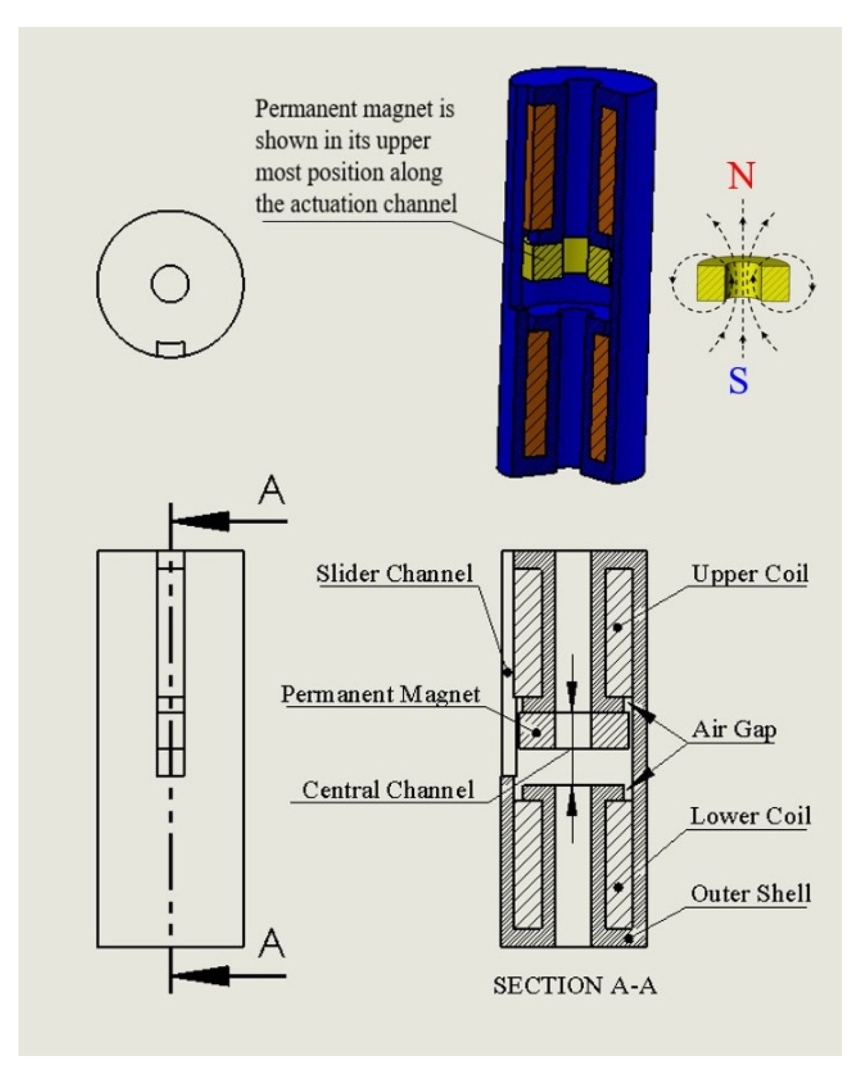
The MaxiMag low-carbon iron was chosen for the actuator’s shell since it is a soft magnetic material with a relative permeability of about 9400, which is much higher than the permeability of other low-carbon steel materials, such as AISI 1018. The B-H curve of the MaxiMag material was supplied by the Tennant Metallurgical Group Ltd. [18], which was required for the electromagnetic finite element simulations of the actuator’s electromagnetic circuit. Figure 1 shows (clockwise from top left) top, isometric, front, and side views of the prototype actuator.
As shown in Figure 1, a channel slot was allowed on the outer surface of the shell to accommodate a rigid sliding link that is used to transfer the inside linear motion of the permanent magnet to a top swivelling part, which was added to permit the angulation required when the actuator is embedded along one of the SLS tools. The rigid slider was designed to be on the side of the shell since there is not enough room inside the actuator. In addition, since a torque is required rather than a direct force actuation, a side location for the slider would increase this torque magnitude and ensures that the whole actuator is within the specified size limit. This sliding channel feature slightly affects the symmetric nature of the actuator structure, which was accounted for in the Ansys finite element assessments of the actuator’s electromagnetic circuit.
For this prototype, a polyurethane-coated solid copper wire with a core and outer diameters of 0.25 and 0.29 mm, respectively was chosen for the coil whilst the applied current was limited to a maximum of 2.7 A in this phase of the actuator’s design. Accordingly, a maximum current density of 32,000 kA/m2 was allowed in the actuator’s electromagnetic circuit simulations.
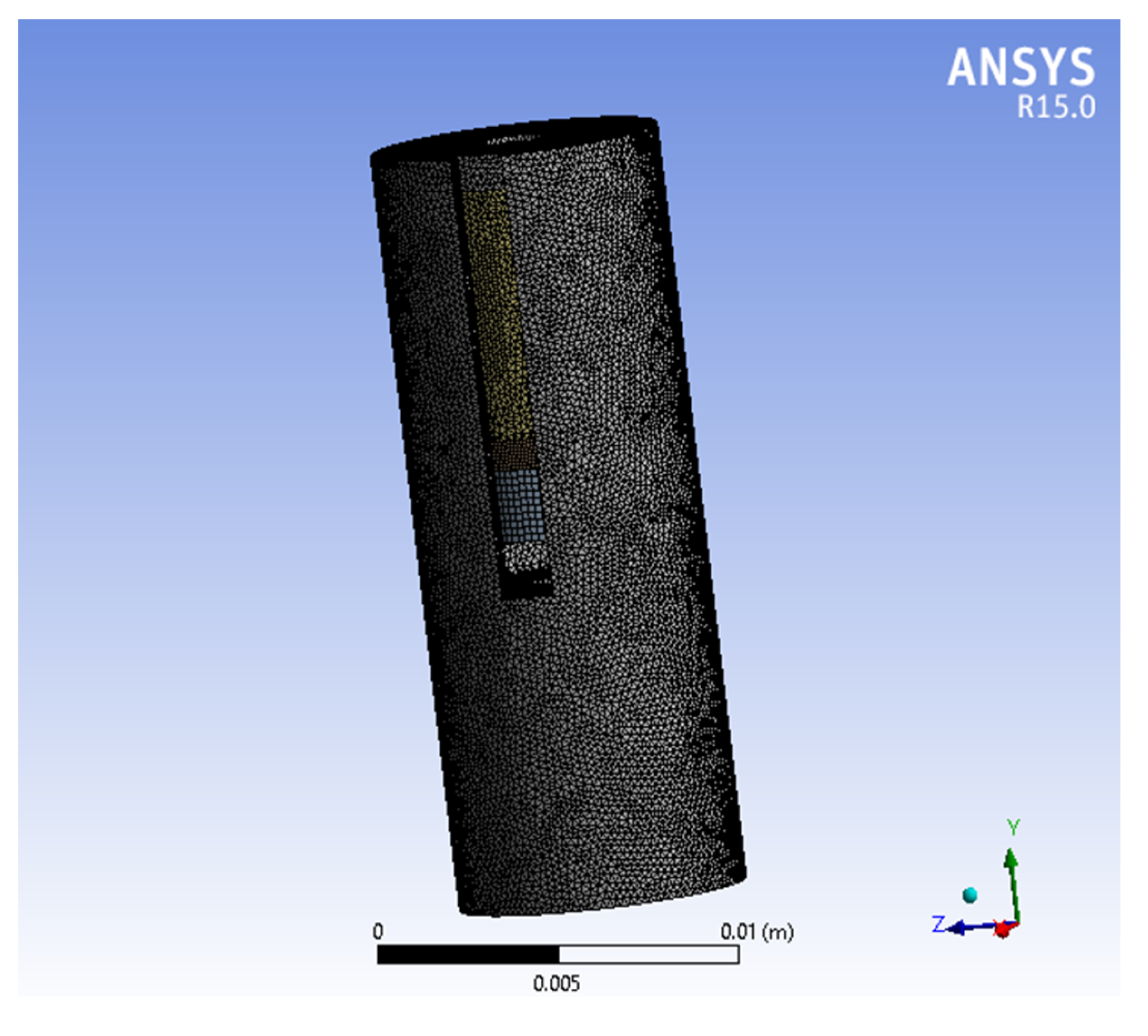
Due to the complicated features of the new actuator, electromagnetic finite element methods are utilised to achieve an accurate design of its electromagnetic circuit, which were carried out using the Ansys software (Version 14, ANSYS Inc., South pointe, OH, USA). The Ansys Workbench software employing the magnetostatic module was utilised to perform a 3D electromagnetic finite element analysis on the actuator’s electromagnetic circuit. These simulations were processed using a 3D geometry of the actuator, which was created using the Solidworks CAD software (Version 2016, Dassault Systèmes SolidWorks Corporation, Waltham, MA, USA) and subsequently imported into the Ansys Workbench environment. The actuator model was then meshed with a maximum element length that was limited to 0.2 mm. The meshed actuator model is shown in Figure 2. The simulated model is embraced by a spherical air ball with a diameter of 0.03 m and the outer surface of this air ball was subjected to a magnetic flux parallel condition of 0 mV. The gravity effect was ignored since the permanent magnet weighs less than 2 g, and hence its effect could only result in a maximum gravity force of about 0.02 N.
The actuator model was created (as per its specifications, Table 1) using the Solidworks CAD software, which was subsequently exported into the Ansys Workbench environment. Moreover, the electric and magnetic properties of the electromagnetic actuator components, which were assumed in the current investigation, are shown in Table 2.
The actuator model was then solved assuming that the permanent magnet was in physical contact with the top end of the actuation channel where one of the electromagnetic coils is located. This coil activation action should permit the magnet to be actuated away from the upper end of the actuation channel as a result of the repulsive force generated by the coil. In Ansys, magnetic forces are computed on the basis of the vector potential method in combination with the inherent characteristics of Ansys solid element type 117. The resulting magnetic force is a sum of Lorentz force, which is due to the magnetic field interaction between the permanent magnet and the coil element, and the Maxwell force that is derived from the Maxwell stress tensor around the ferromagnetic regions. Surface integral methods were also utilised in the calculation of the magnetic forces at the element level.
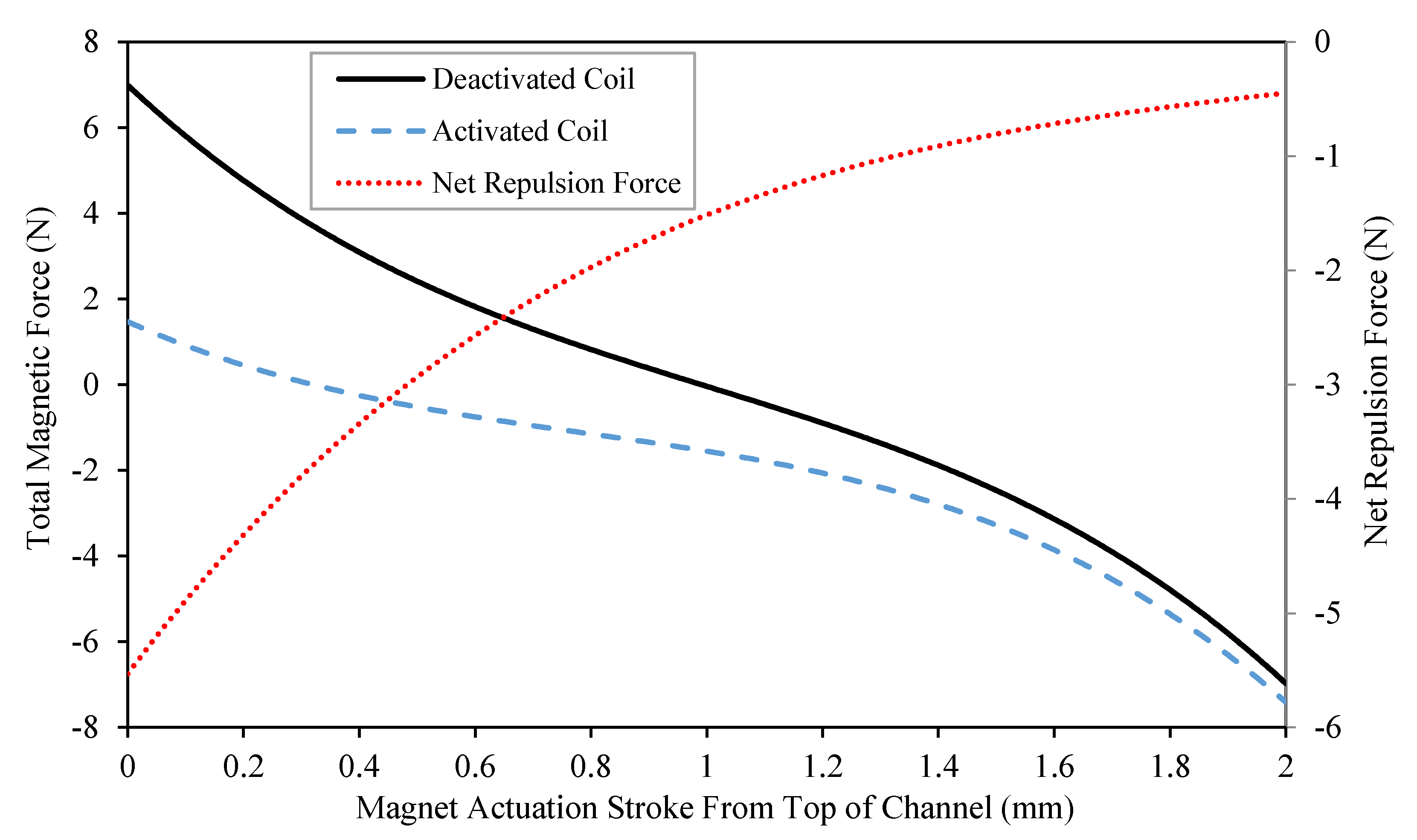
The total magnetic force estimated on the permanent magnet versus the 2 mm long actuation stroke, when the magnet is assumed to slide from the actuation channel’s upper end towards its lower end, is shown in Figure 3. In this figure, the results are shown for the two cases when the nearby coil was deactivated and activated. It is clear that when the coil is deactivated, the total magnetic force on the permanent magnet becomes neutral at the stroke mid-point, which is happening because of the axisymmetric nature of this prototype. When the coil is activated, the total magnetic force measured at the magnet at any point along its stroke from the upper end to the lower end of the actuation channel would be the difference between the attraction and repulsion forces generated by the permanent magnet and the coil, respectively.
Net repulsive magnetic forces generated by the coil are also shown in Figure 3, which are estimated as the difference between the activated and deactivated results. It is apparent that the activated coil effect becomes weaker as the magnet travels further towards the other end of the actuation channel. It should be noted that, considering the initial design of this prototype, the total magnetic force measured on the permanent magnet is still positive (attraction) when the stroke is zero and the coil is activated, which means the magnet cannot be actuated by magnetic fields away from the upper end of the actuation channel. However, further optimisations of this prototype, reported in Section 3, will detail the steps carried out to make sure that the resulting force becomes negative (repulsive), which allows the magnet to be actuated towards the other end of the channel.

2.2. Actuator Design Optimisation

The prototype actuator was optimised when the eight parameters (identified in Section 2), which affect the performance of the new actuator, were systematically assessed. This approach is detailed below:

2.2.1. Position and Size of Air Gap

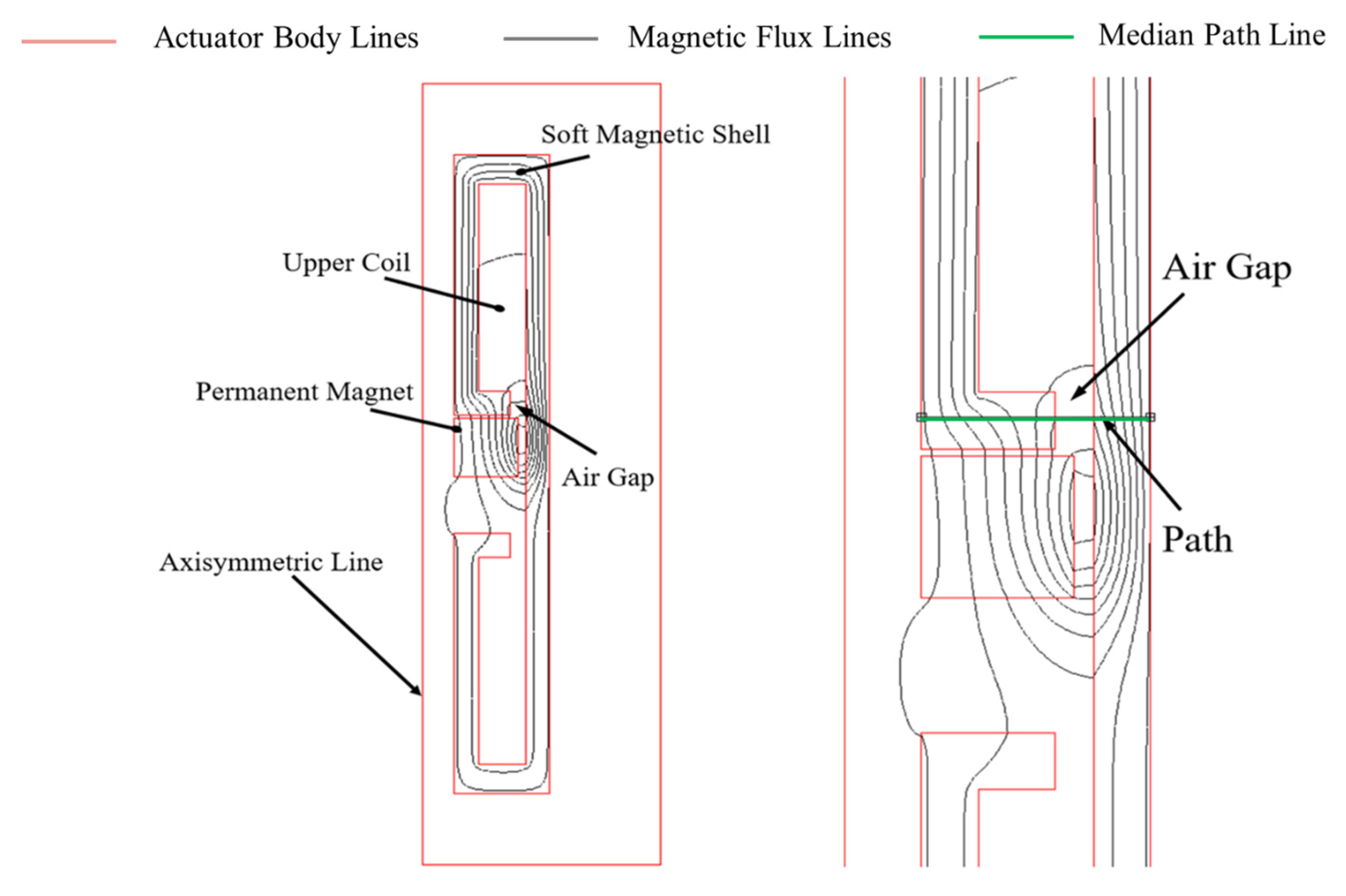
A soft magnetic material with high relative permeability was proposed for the new actuator’s magnetic circuit in order to maximise the efficiency of the magnetic path through which the generated magnetic field passes. However, and whilst the high permeability of this material offers a stronger path for the magnetic field generated by the coil, it discourages this field’s interaction with the permanent magnet, which would result in a weaker actuation force. In order to assess this design issue further, 2D axisymmetric electromagnetic finite element simulations using the Ansys software were conducted. Initially, the permanent magnet was assumed to be attached to the upper end of the actuation channel and the nearby (upper) coil was in its activated state. Figure 4 shows the contour plot of the magnetic flux line density in the body of the actuator. Moreover, in this figure, an imaginary median path (shown in green) was virtually defined in the soft magnetic material between the magnet and the coil along which the vector sum magnetic flux density values (√(Bx2 + By2 + Bz2)) were estimated and presented in Figure 5. It can be seen that the peak magnetic field density occurs around 2 mm (measured from the left side) along this path.
It was then found that an air gap that is introduced in this area (Figure 6) encouraged the field generated by the coil to weave and penetrate itself closer to the permanent magnet. The size and position of the proposed air gap greatly affect the efficiency of the electromagnetic circuit and hence, the performance of the new actuator. Consequently, it is vital to develop the electromagnetic circuit of the new actuator with the best possible combination of these two important factors, which were investigated systematically. Accordingly, the optimum size and position of this air gap and hence, the best interaction between the magnet and the coil was achieved when an air gap of about 0.5 mm wide was introduced at a location that is about 1.75 mm along the median path. The effect of introducing this air gap, which is again designed to stop the magnetic field lines shortcutting their circuit in the soft magnetic material surrounding the coil, on the distribution of the magnetic field across the actuator’s body is shown in Figure 7. As a result, a better field interaction is achieved with the permanent magnet, which is indicated by the distribution of the magnetic flux density along the imaginary median path (also shown in Figure 5) where the air gap effect is clearly illustrated in comparison with the case when a solid magnetic material was allowed to surround the coil.

2.2.2. Interaction between Coils

The design of the new actuator was modified when a second coil was added just below the lower end of the actuation channel, as illustrated in Figure 1. Since the whole actuator structure is symmetric, it is expected that when the top end coil is activated, a repulsion force is generated to drive the magnet away from the top end of the channel, which increasingly becomes under the action of an attraction force generated by the lower end coil after it passes the middle point of the actuation stroke.
Figure 7 shows the results after both coils were activated simultaneously with the same current density (32,000 kA/m2) but with opposite current flow directions to generate the required repulsion and attraction forces by the upper and lower coils, respectively whilst the magnet completes its stroke from the top end to the lower end of the actuation channel. For comparison, the results for the cases, when only the top end coil is activated and none of the coils is activated, are also shown in this figure. It can be seen that when the two coils are activated, the total magnetic force on the magnet marginally increased by about 0.3 N compared with the one coil activation case.
According to these results, the far-end coil could be ignored during the actuation of the magnet, which could be driven only by the repulsive action generated by the activated near-end coil. This means that the heat generation is cut in half since only one coil is activated during the actuation process. However, two coils are still needed as the far-end coil becomes a near-end coil in the next actuator motion.

2.2.3. Current Density of Coils

It is obvious that an increase in the current density of the coil could enhance the performance of the actuator by generating a stronger magnetic field required to overcome the action of the permanent magnet when an actuation is initiated. A feature of this type of actuators is that the attraction force between the magnet and the iron works against the repulsion force induced between the coil and the magnet. Therefore, the current density should be as large as possible to enhance the latter force, but there must be a balance between the high current density setting and the damaging heat generation level.
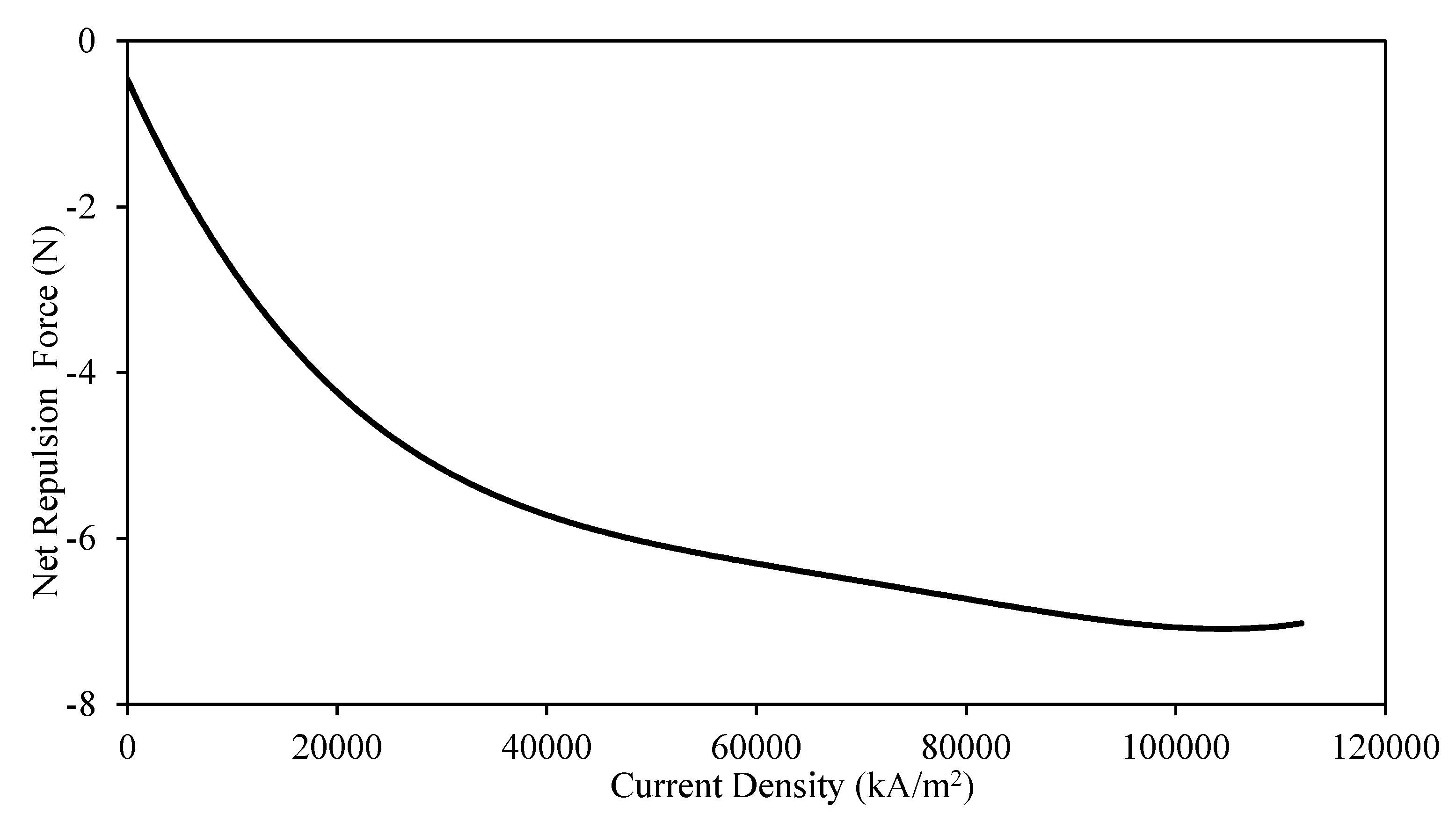
Taking these facts into account, further trials were conducted when the performance of the prototype actuator was simulated using the Ansys software for different current densities. Net repulsive magnetic forces acting on the magnet that is assumed to be at its zero-stroke position, which are again estimated as the difference between the activated and deactivated force results versus the coil current density are shown in Figure 8.
It can be seen, Figure 8, that the rise in the current density could boost the force output of the actuator. However, while the current density continues to rise, the rate of increase of the force output becomes gradually smaller, which is ascribed to the fact that the actuator’s material reaches its magnetic saturation limit [21]. Based on these results, the current density that would contribute to the optimum operation of the new actuator was chosen to be approximately 80,000 kA/m2, which corresponds to a current instantaneously applied to the coil of about 6.7 A.

2.2.4. Size of Actuator’s Outer Shell

In the current clinical practice, most SLS trocars have a maximum diameter of around 12 mm. Accordingly, it was decided that the outer diameter of the new actuator should not exceed this size limit, which includes the thickness of the insulation layer that is used for sealing the actuator.
Several trials were made to increase the size of the initial actuator prototype up to a maximum diameter of 10 mm. Clearly, larger actuator shells permit more internal space to accommodate a larger coil and permanent magnet, which had a significant positive effect on the actuation force.
A comparison between the performance of actuators with diameters of 8 and 10 mm is shown in Figure 9 in terms of the net repulsion forces, which were estimated on the permanent magnet along its stroke between the two ends of the actuation channel. It can be seen that the net repulsion force delivered by the 10 mm actuator is approximately 25% larger than that delivered by the 8 mm actuator. This is happening since the change in the level of the attraction force generated by the larger permanent magnet is smaller than that produced by the coil element of the actuator with a larger diameter. However, due to design requirements for laparoscopic applications, it was decided that the outer diameter of the new actuator should not be increased any further.

2.2.5. Size of Coil

A larger coil would be expected to enhance the magnetic interaction between the coil and the permanent magnet. It is clear that the coil size cannot be increased laterally due to restrictions imposed on the overall diameter of the actuator. Moreover, an increase in the coil height would increase the whole length of the actuator whilst a shorter actuator permits more joints to be mounted along the surgical tools, resulting in a better overall tool flexibility. Therefore, the balance between the actuator force output and its size was required to be optimised. In this activity, all design parameters were maintained except the height of the coil, which was changed from 1 to 11 mm. The net repulsion forces estimated on the permanent magnet in its zero-stroke position versus the coil height are shown in Figure 10.
It can be seen that increasing the coil height beyond 7 mm does not contribute to any improvement in the actuator performance. Hence, 7 mm was set as the coil height in the present actuator design.

2.2.6. Size of Permanent Magnet

The magnetic interaction between the coil and the permanent magnet could also be increased with the growth of the magnet size. However, there is a little tolerance available laterally as the inner and outer diameters of the magnet have already been decided on according to the diameters of the central channel and the whole actuator, respectively. The only variable in this part that could be optimised is the thickness of the permanent magnet.
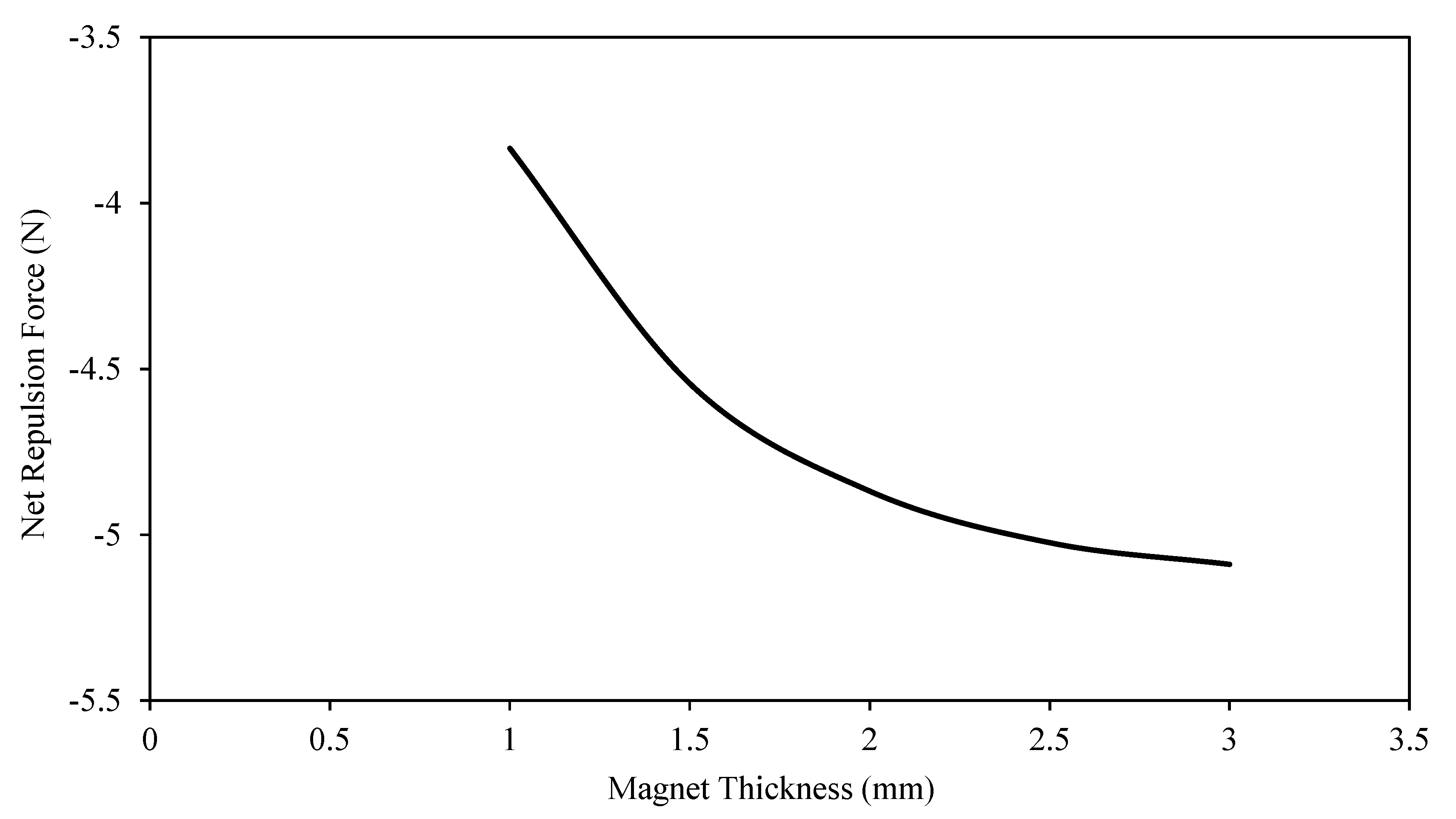
Normally, a bigger magnet would generate a stronger magnetic field, which could increase both its interaction with the coil and its attraction to the actuator’s soft magnetic material. However, it is not easy to determine the real effect of increasing the magnet thickness on the actuation force without the electromagnetic finite element simulations. Therefore, several simulations were conducted when the magnet thickness was changed between 1.0 and 3.0 mm whilst the rest of the parameters were maintained as those in the reference model.
Net repulsive magnetic forces generated by the coil versus the thickness of the permanent magnet during its zero-stroke position are shown in Figure 11.
It was apparent that while the attraction force increased with the magnet thickness, the resulting repulsion forces (Figure 11) dropped their rate of increase drastically when the magnet is approximately thicker than 2.0 mm. This is attributed to the fact that the coil effect is gradually degraded with increasing attraction forces generated by thicker magnets and therefore, the magnet needs to be as thin as possible to ensure that the net magnetic force becomes repulsive when the coil is energised. However, it was decided that the above 2.0 mm magnet thickness boundary will serve both the attraction and repulsion force requirements and consequently, a 2.0 mm thick magnet is recommended for the current design of the new actuator.

2.2.7. Grade of Permanent Magnet

The grade of the permanent magnet is considered as a major factor to determine its strength. Residual induction (Br) and coercive force (Hc) are the two main parameters usually used to decide on the permanent magnet strength. These two parameters were inputted into the Ansys finite element simulations to define the properties of the different magnets assessed in this investigation. Three types of magnets were used to determine the effect of different magnet grades on the efficiency of the electromagnetic circuit of the new actuator. These were neodymium (NdFeB), samarium–cobalt (SmCo), and Ferrite. The detailed parameters of these different magnets are shown in Table 3.
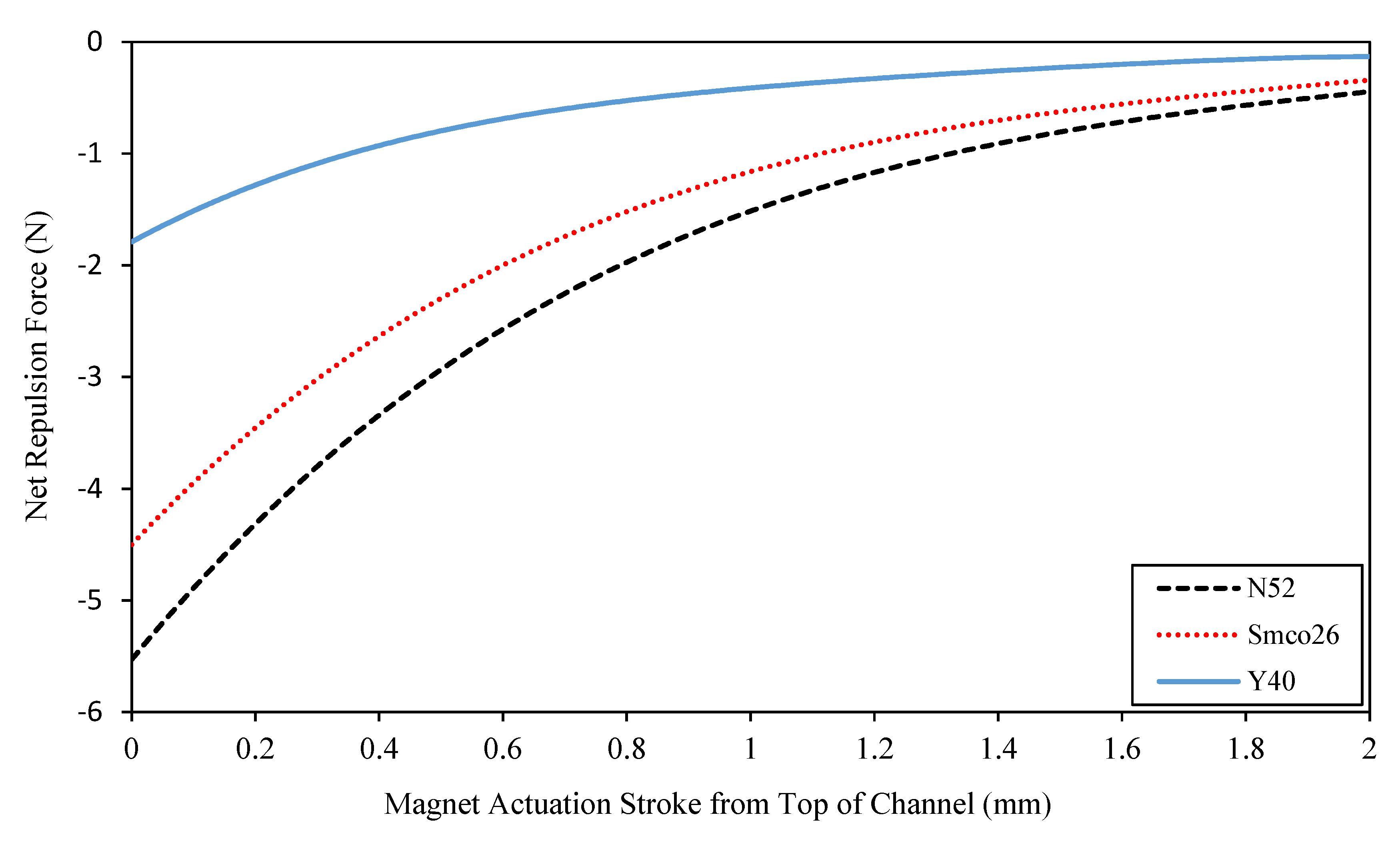
While the rest of the design parameters were the same as those in the reference model, the Ansys code was again used to assess the effect of the permanent magnet strength on the actuation force. The attraction force results have shown that the most powerful magnet was the NdFeB magnet whilst the Ferrite magnet was the weakest among the three magnets. The net repulsive magnetic forces generated by the coil were estimated, which are shown in Figure 12 for the three permanent magnets during their strokes between the two ends of the actuation channel.
The results show that a stronger magnet would contribute to a better magnetic interaction with the activated coil, which results into larger actuation forces. In addition, these forces are seen to be dramatically reduced along with the magnetic strength of the permanent magnet. Hence, the Neodymium (NdFeB) magnet was chosen for this actuator design.

2.2.8. Height of Actuation Channel

As mentioned earlier, the aim of the new actuator would be to provide bending motions by transferring the linear actuation of the magnet to a swivelling mechanism through a solid slider element. However, published reports have suggested that balancing force output and flexibility in minimally invasive surgical tools has been proven to be a difficult task [24]. This balance was considered as a key design factor in the current actuator development.
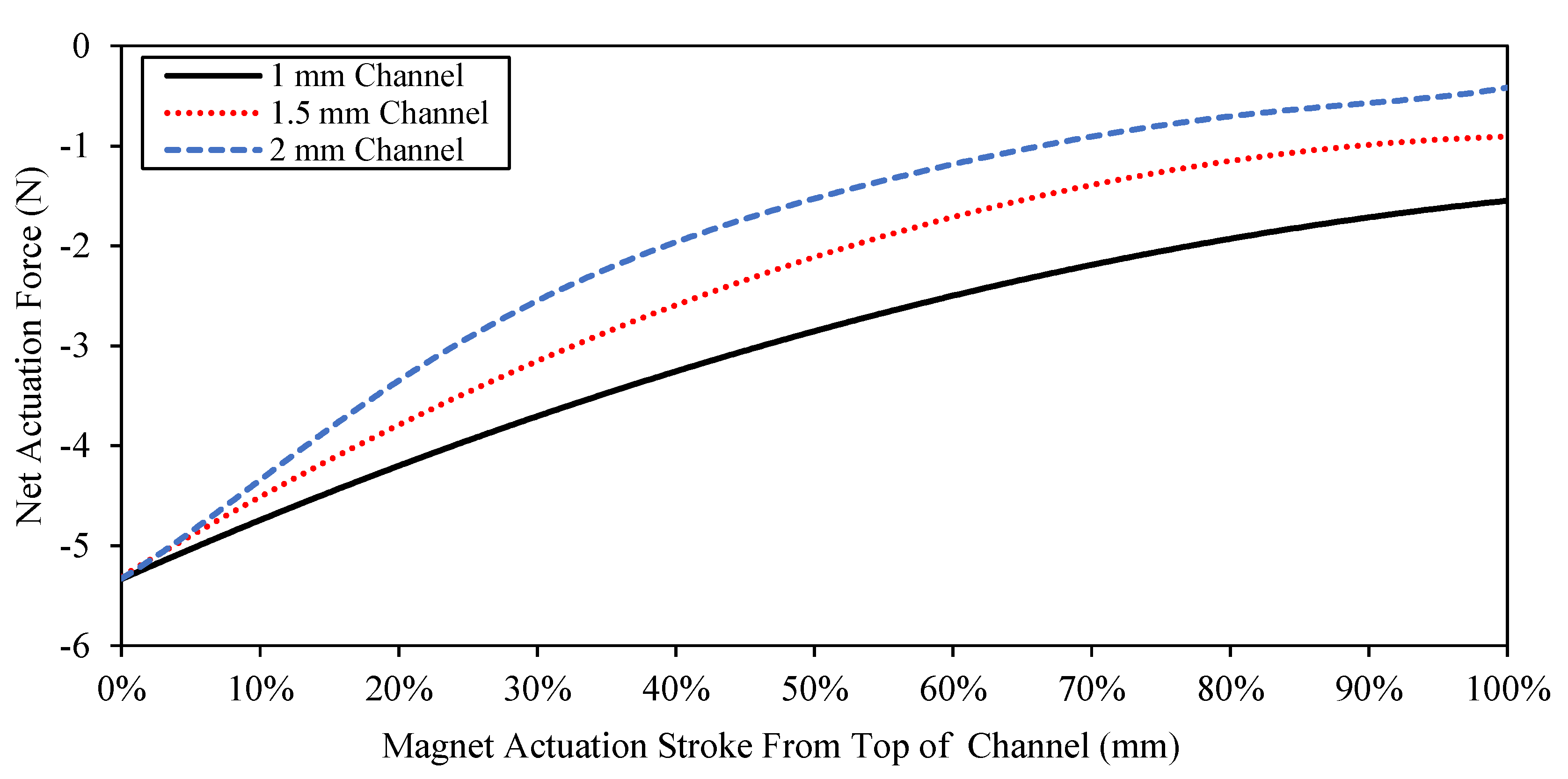
In order to optimise the force performance of the new actuator as well as its linear range and hence, its optimum bending angle, several simulations were conducted when the height of the actuation channel was changed between 1.0 and 2.0 mm, which should be sufficient to produce bending angles between 22 and 43°, whilst the other parameters were maintained as those in the reference model. The results of this assessment are shown in Figure 13 in terms of the net repulsion forces, which were estimated on the permanent magnet along its stroke between the top and lower ends of the actuation channel.
The results show that the net repulsion force decreases with increasing channel height, which means that the magnetic interaction of the coil with the magnet is less efficient with a longer actuation channel. In addition, longer actuation channels show that the attraction forces are larger than the repulsion forces and therefore, it would not be possible to initiate the actuation of the magnet away from its holding position. Consequently, it was decided that on balance, a channel height of 1.5 mm, resulting into a 30° bending angle, would be efficient for the current design of the new actuator.

2.3. Mechanical Design of New Actuator

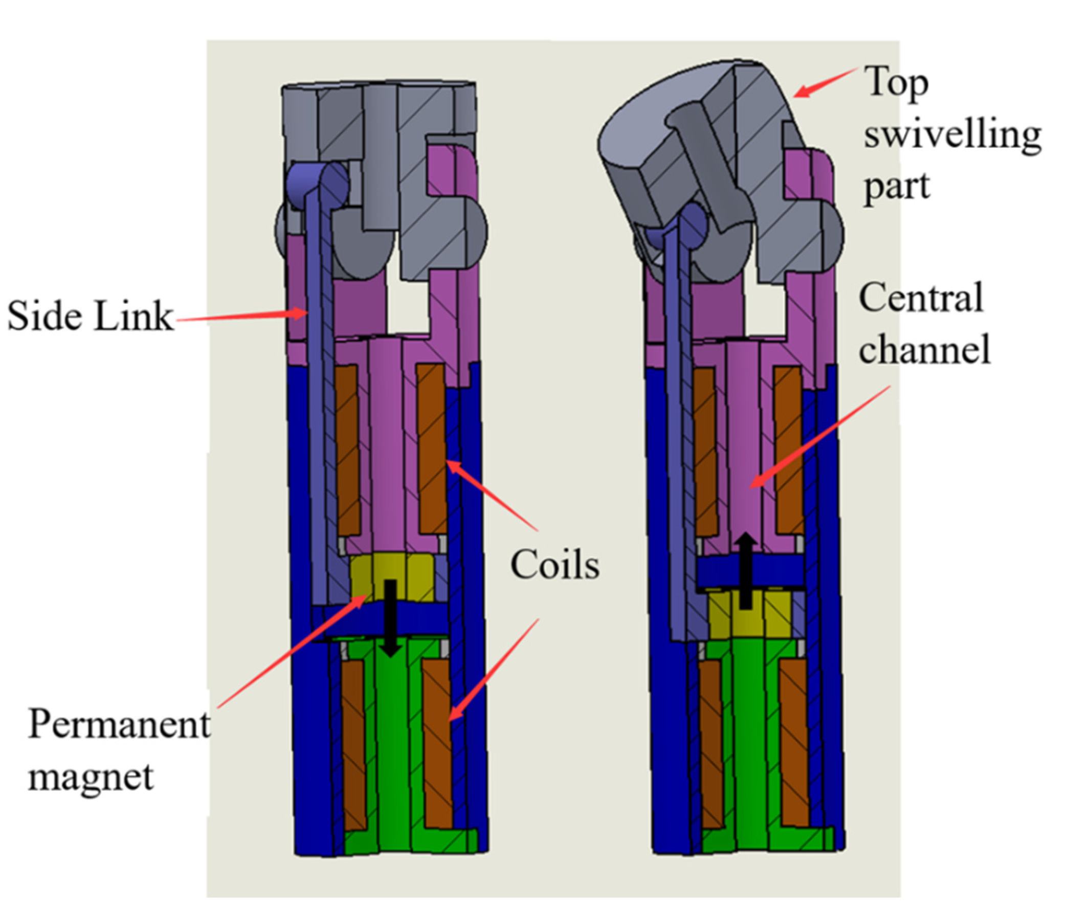
In order to transfer the magnet linear motion into a bending motion when the actuator is incorporated along SLS tools, a channel slot was designed on the outer surface of the actuator shell to accommodate a rigid sliding link that is hinged into a swivelling component at the end of the actuator, as shown in Figure 14. As stated in Section 2, the rigid slider was designed to be on the side of the shell since there is not enough room inside the actuator. In addition, this sliding link cannot be passed through the central channel of the actuator where there is a requirement to pass a guiding wire to control the end effector of SLS tools. More importantly, and since a torque is required rather than just a direct force for the actuation of the swivelling part, a side location for the slider would increase this torque magnitude and ensures that the whole actuator is within the specified size limit.
The proposed electromagnetic actuator has two stable latching operations along a single quadrant. These are the two positions when the permanent magnet is attracted to either the upper or lower end of the actuation channel. The transition between these two locations is activated under the effect of the repulsion force generated by the electromagnetic coil (energised by a pulse current signal) located nearby the channel end where the permanent magnet resides so that the magnet can be actuated towards the other end of the channel before it becomes attached to it under the latching mechanism effect. Again, this linear motion of the permanent magnet along the actuation channel is converted into a bending motion that is achieved through the swivelling mechanism at the top end of the actuator, Figure 14. Therefore, when one of the developed electromagnetic actuators is embedded along one of the SLS tools, it should change the bending of the tool by the full actuator angle of 30° when the surgeon pushes a button that would allow the pulse current supply to the corresponding electromagnetic coil and the tool should regain its straight position when the button is pressed again to supply the current pulse to the opposite electromagnetic coil. The actuator is designed so that no control is required during the transition stroke, which takes place over a period of few milliseconds between the two ends of the actuation channel.
It is proposed to stack more than one actuator along SLS tools to provide them with a multi-degree-of-freedom actuation, which should be controlled by the current sources that are separately connected to the individual actuators. For normal laparoscopic surgical tools, it is planned to stack 3–4 actuators (joints) along their body when each actuator is expected to contribute an angulation of about 30°. This is considered as a realistic operational target since each actuator, including its swivelling component, has a total length of about 31 mm and hence, 3–4 joints would make a full tool length of 93–124 mm, which should permit at least six degrees-of-freedom. The flexibility and angulation of the proposed assembly is illustrated in Figure 15.
Various design parameters of the new actuator were analysed separately and sequentially to identify their individual effects on the actuator’s performance. This sequential single parameter optimisation method has served the current phase of the actuator design process well, and the authors have planned to utilise a multivariable parameter optimisation approach in their future work on the development of this actuation system and its ultimate biomedical applications. A summary of the design parameters of the optimised actuator are listed in Table 4.
Using a conventional CNC machining facility, the new actuator was then manufactured, which was based on the optimised design parameters. The machined parts were subsequently annealed in order to regain the original magnetic properties of the material and also to remove any carbon residue from the surface of the parts. Figure 16 shows the manufactured actuator including an extension at the end of its swivelling component.
It should be noted that the relatively large wire diameter of 0.25 mm, which was used in the current design of the new actuator prototype, was deemed to be safe enough for this laboratory investigation phase of the project. However, in the planned future work, which involves dummy and patient trials, the electromagnetic coil element of the new actuator will be manufactured using micro-sized wires in order to reduce the level of the required current to produce the same magnetic output. Low-current excitation of electromagnetic devices is considered as a critical issue when they are aimed for biomedical applications [25].

3. Results and Discussion

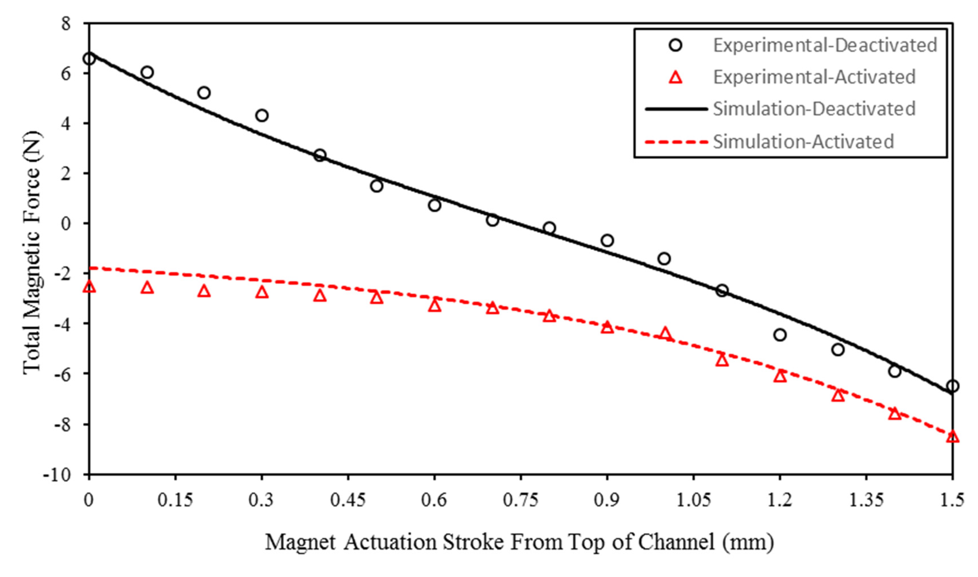
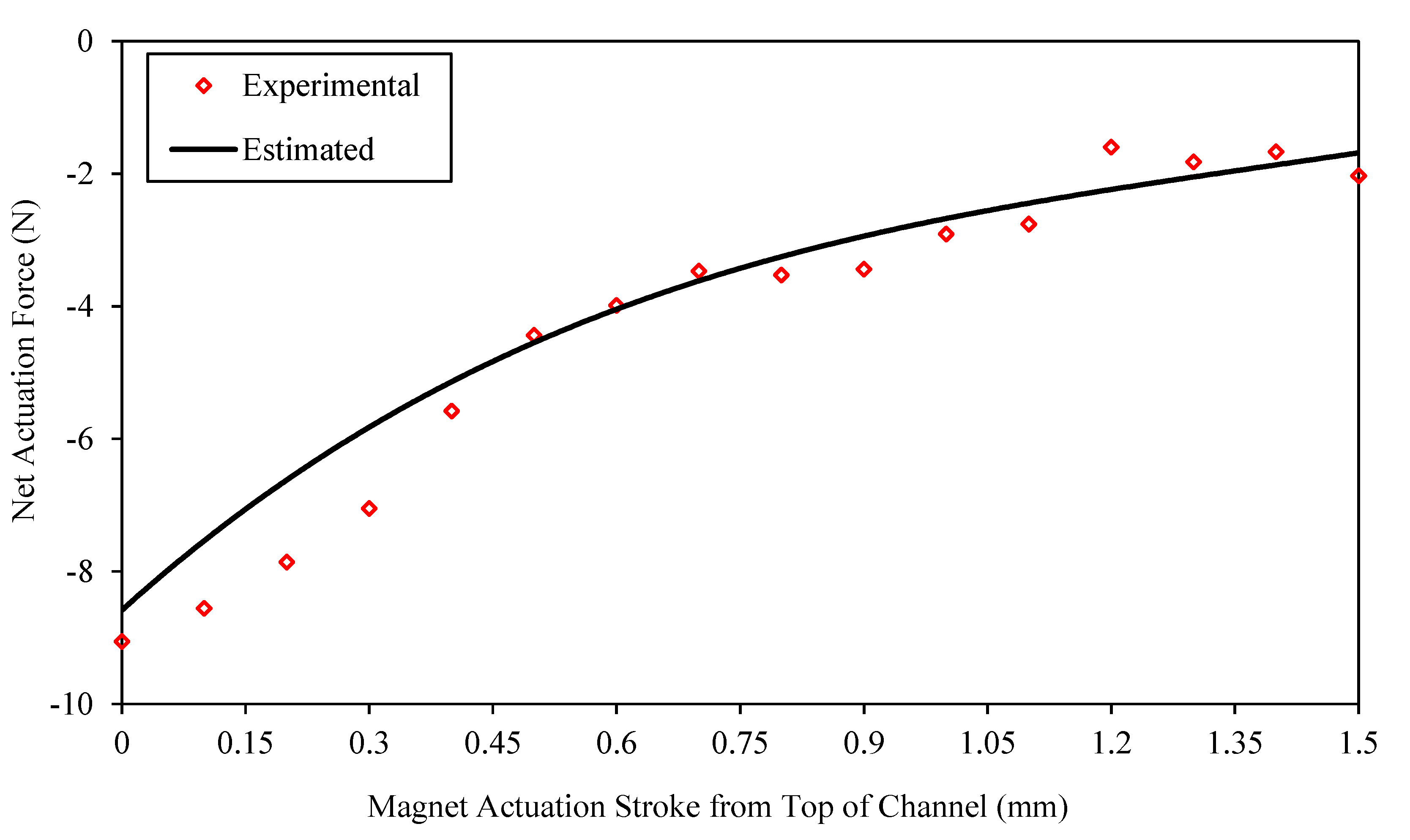
This new actuator was experimentally tested using a Tinius Olsen tensile machine (Tinius Olsen, Horsham, PA, USA), model H5KS. In this arrangement, the flat end of the shell of the actuator was connected to the 10 N load cell of the tensile machine using a screw clamping mechanism whilst the permanent magnet armature was bonded to a small rod that passed through the central channel of the actuator and connected to the basement of the tensile machine. Moreover, a special circuit was designed for generating a single short pulse of current of 6.7 A with an operative time that could be adjusted between 0.1 and 1 s, which was applied to energise the magnetic circuit of the actuator. Controlled input axial displacements were provided by the tensile machine, and for each position of the permanent magnet along the actuation stroke, the total magnetic force was measured by the load cell of the tensile machine while the coil was deactivated. The test was repeated when for each input displacement level, the coil was energised with a current pulse of 0.1 s operative time and the peak force measured by the load cell was recorded as the total magnetic force. In addition, the performance of the optimised actuator was again determined using the Ansys software. Figure 17 shows a comparison between the measured and modelled total forces of the new actuator. Net repulsive forces were then estimated as the difference between the activated and deactivated force results, which are presented in Figure 18. Although the experimental force results and those obtained through the numerical modelling seem to follow the same trend across the magnetic actuation stroke, the small difference between them could be ascribed to the fact that the prototype electromagnetic actuator, due to various manufacturing and experimental deviations, may not exactly produce the magnetic field that is assumed numerically, which could affect the output of the actuator. However, the close agreement between the two sets of results should confirm the validity of the finite element modelling technique that was applied in this study.
It can be seen that for the optimised actuator design, the permanent magnet is capable of generating a force in excess of 6.8 N when it is attracted to the end of the channel (deactivated coil), which should be sufficient to lock the actuator in the required position. In addition, a net repulsive force of approximately 9 N (Figure 18) was measured when the coil is activated, which should be strong enough to drive the magnet away from the near-end towards the far-end of the actuation channel. This actuator output, despite losing the space of the central gap that was designed to accommodate the end effector wire, compares favourably with the electromagnetic actuation systems developed by Suzumori and Yoshikawa [15], Besuchet et al. [26], and Roschke et al. [27] when output forces of 0.6, 1.35, and 11 N were achieved, respectively. It should be noted that the 11 N force reported by Roschke et al. [27] was delivered by an actuator which is 2.5 times larger than the developed latching electromagnetic actuator. In addition, the total size of the developed actuator could still be increased without breaching the limits imposed by SLS procedures, which should contribute to further improvements in the above force levels.
In this investigation, it has been shown that the force output of the developed miniature actuator was adequate to initiate the angulation required in SLS procedures. It is worth mentioning that none of the currently available actuation technologies allow for the construction of a modular and back-drivable articulated system with a high force output and a small footprint capability, which is suitable for SLS applications [15,26,27]. In addition, the new actuator, which was thermally proven to be safe [28], weighs about 25 g and therefore, it is expected that any gravity effects would almost have no impact on the position control of the actuator. Furthermore, this actuator is capable of generating torques larger than 45 mNm, which is based on a 9 N driving force in association with a 5 mm offset that was allowed between the hinges of the side sliding link and the top swivelling component. The estimated overall performance of the new actuator is summarised in Table 5, which is benchmarked against the performance of other actuators already reported in the literature. According to this table, the torque and force output of the new actuator were found to be adequate to generate the angulation required by SLS tools. This was achieved despite the miniaturised size of the new actuator that was energised by a low voltage feed in comparison with the relatively large actuators (reported in Table 4), which employed large power units and complex power transmission (see for example, the fluidic actuator requirements, including the need for a fluid tank [29]).

4. Conclusions

In this study, different factors for developing a miniature latching-type electromagnetic actuator were analysed and optimised. In particular, the new actuator was designed to be embedded at selected joints along single-port laparoscopy instruments to enhance their level of stiffness and degrees-of-freedom without compromising patient safety.
The developed electromagnetic actuator is comprised of electromagnetic coil elements, a solid shell made from soft magnetic material and a permanent magnet that is used to enhance the magnetic field along the force generation path and provide the latching effect. The embedded latching feature allows the actuator to lock into certain positions when its magnetic circuit is not activated. It was found that a short pulse of current supply to the coil element would be sufficient to generate the magnetic field required for actuation.
In this paper, electromagnetic finite element analyses were conducted using the Ansys software to design and optimise the actuator’s electromagnetic circuit. Moreover, the new actuator was manufactured and experimentally tested using a tensile machine setup and its performance was found to agree well with that numerically estimated. This confirmed the validity of the finite element approach used in the current actuator design investigation. Finally, the optimised performance of the new actuator was analysed and was found to be satisfactory for applications in single-port laparoscopic surgery.

Author Contributions

All authors listed have made a substantial, direct and intellectual contribution to the work, and approved it for publication. All authors have read and agreed to the published version of the manuscript.

Funding

This work is supported by the Wellcome Trust through a translational medical research fund 120 804894.

Conflicts of Interest

The authors declare no conflict of interest.

References

  1. Miernik, A.; Schoenthaler, M.; Lilienthal, K.; Frankenschmidt, A.; Karcz, W.; Kuesters, S. Pre-bent instruments used in single-port laparoscopic surgery versus conventional laparoscopic surgery: Comparative study of performance in a dry lab. Surg. Endosc. 2012, 26, 1924–1930. [Google Scholar] [CrossRef] [PubMed]
  2. Rané, A.; Rao, P.; Rao, P. Single-port-access nephrectomy and other laparoscopic urologic procedures using a novel laparoscopic port (r-port). Urology 2008, 72, 260–263. [Google Scholar] [CrossRef] [PubMed]
  3. Paranjape, C.; Ojo, O.; Carne, D.; Guyton, D. Single-incision laparoscopic total colectomy. J. Soc. Laparosc. Robot. Surg. 2012, 16, 27–32. [Google Scholar] [CrossRef] [PubMed] [Green Version]
  4. Paek, J.; Nam, E.; Kim, Y.; Kim, S. Overcoming technical difficulties with single-port access laparoscopic surgery in gynecology: Using conventional laparoscopic instruments. J. Laparoendosc. Adv. Surg. Tech. 2011, 21, 137–141. [Google Scholar] [CrossRef]
  5. Zani, A.; Ade-Ajayi, N. Flexible-tip laparo-endoscopic surgery: A bridge to single port appendicectomy in children. Eur. J. Pediatric Surg. 2011, 21, 322–324. [Google Scholar] [CrossRef]
  6. Stolzenburg, J.; Kallidonis, P.; Oh, M.; Nabi, G.; Do, M.; Haefner, T.; Dietel, A.; Till, H.; Sakellaropoulos, G.; Liatsikos, E. Comparative assessment of laparoscopic single-site surgery instruments to conventional laparoscopic in laboratory setting. J. Endourol. 2010, 24, 239–245. [Google Scholar] [CrossRef] [Green Version]
  7. Satava, R.; Ellis, S. Human interface technology. Surg. Endosc. 1994, 8, 817–820. [Google Scholar] [CrossRef]
  8. Can, S.; Staub, C.; Knoll, A.; Fiolka, A.; Schneider, A.; Feussner, H. Design, Development and Evaluation of a Highly Versatile Robot Platform for Minimally Invasive Single-port Surgery. In Proceedings of the 2012 4th IEEE RAS & EMBS International Conference on Biomedical Robotics and Biomechatronics (BioRob), Rome, Italy, 24–27 June 2012; pp. 817–822. [Google Scholar]
  9. Cianchetti, M.; Ranzani, T.; Gerboni, G.; De Falco, I.; Laschi, C.; Menciassi, A. STIFF-FLOP Surgical Manipulator: Mechanical Design and Experimental Characterization of the Single Module. In Proceedings of the 2013 IEEE/RSJ International Conference on Intelligent Robots and Systems, Tokyo, Japan, 3–7 November 2013. [Google Scholar]
  10. Sonetha, V.; Agarwal, P.; Doshi, S.; Kumar, R.; Mehta, B. Microelectromechanical systems in medicine. J. Med. Biol. Eng. 2017, 37, 580–601. [Google Scholar] [CrossRef]
  11. Le, H.; Do, T.; Phee, S. A survey on actuators-driven surgical robots. Sens. Actuators A Phys. 2016, 247, 323–354. [Google Scholar] [CrossRef]
  12. Zárate, J.; Tosolini, G.; Petroni, S.; De Vittorio, M.; Shea, H. Optimization of the force and power consumption of a microfabricated magnetic actuator. Sens. Actuators A Phys. 2015, 234, 57–64. [Google Scholar] [CrossRef] [Green Version]
  13. Madani, K.; Khanmohammadi, S.; Azimirad, V. Finding optimal actuation configuration for magnetically driven capsule endoscopy based on genetic algorithm. J. Med. Biol. Eng. 2016, 36, 776–787. [Google Scholar] [CrossRef]
  14. McIntosh, E.; Ellis, J. Note: A simple model for thermal management in solenoids. Rev. Sci. Instrum. 2013, 84, 116106. [Google Scholar] [CrossRef] [PubMed]
  15. Suzumori, K.; Yoshikawa, M. Micro linear electromagnetic solenoid. Tran. Jpn. Soc. Mech. Eng. Ser. C 2003, 69, 3416–3421. [Google Scholar] [CrossRef] [Green Version]
  16. Kim, J.; Chang, J. A new electromagnetic linear actuator for quick latching. IEEE Trans. Magn. 2007, 43, 1849–1852. [Google Scholar] [CrossRef]
  17. Dos Santos, M.P.S.; Ferreira, J.A.F.; Ramos, A.; Simões, J.A.O.; Morais, R.; Silva, N.M.; Santos, P.M.; Reis, M.J.C.S.; Oliveira, T. Instrumented hip implants: Electric supply systems. J. Biomech. 2013, 46, 2561–2571. [Google Scholar] [CrossRef]
  18. Electromagnetic Test on Cast 80626; Tennant Metallurgical Group Ltd.: Chesterfield, UK. 2014. Available online: http://www.tenmet.co.uk/ (accessed on 21 May 2020).
  19. El Wahed, A.K. A novel hydraulic actuation system utilizing magnetorheological fluids for single-port laparoscopic surgery applications. Materials 2020, 13, 1380. [Google Scholar] [CrossRef] [Green Version]
  20. Dos Santos MP, S.; Marote, A.; Santos, T.; Torrão, J.; Ramos, A.; Simões, J.A.; Silva, O.A.B.d.e.; Furlani, E.P.; Vieira, S.I.; Ferreira, J.A.F. New cosurface capacitive stimulators for the development of active osseointegrative implantable devices. Sci. Rep. 2016, 6, 30231. [Google Scholar] [CrossRef]
  21. Hurricks, P.L. Handbook of Electromechanical Product Design; Longman Scientific & Technical: Harlow, UK, 1994; pp. 303–304, 306–308, 320–324. [Google Scholar]
  22. Magnet Grade Chart; Amazing Magnets, LLC: Anaheim, CA, USA. 2015. Available online: https://www.amazingmagnets.com/magnetgrades.aspx (accessed on 21 May 2020).
  23. E Magnets UK Ferrite/Ceramic Data Sheet”; “E Magnets UK NDFeB/Neodymium Data Sheet,”; “E Magnets UK Samarium Cobalt Data Sheet; Bunting Magnetics Europe Limited: Hannover, Germany, 2015. Available online: https://www.buntingeurope.com/ (accessed on 21 May 2020).
  24. Vitiello, V.; Lee, S.; Cundy, T.; Yang, G. Emerging robotic platforms for minimally invasive surgery. IEEE Rev. Biomed. Eng. 2013, 6, 111–126. [Google Scholar] [CrossRef]
  25. Bernardo, R.; Rodrigues, A.; dos Santos, M.P.S.; Carneiro, P.; Lopes, A.; Amaral, J.S.; Amaral, V.S.; Morais, R. Novel magnetic stimulation methodology for low-current implantable medical devices. Med. Eng. Phys. 2019, 73, 77–84. [Google Scholar] [CrossRef]
  26. Besuchet, R.; Gabella, A.; Perriard, Y. Design of a miniature short-stroke constant-force linear actuator. Appl. Mech. Mater. 2013, 416, 109–114. [Google Scholar] [CrossRef]
  27. Roschke, T.; Fraulob, S.; Seiler, R.; Bodrich, T. Bipolar Magnetic Actuators and Approaches for their Design. In Proceedings of the 10th European Space Mechanisms and Tribology Symposium, San Sebastián, Spain, 24−26 September 2003; pp. 209–215. [Google Scholar]
  28. Wang, H.C.; El Wahed, A.K. The performance of a novel latching-type electromagnetic actuator for single-port laparoscopic surgery. J. Mod. Phys. 2019, 10, 1659–1673. [Google Scholar] [CrossRef] [Green Version]
  29. Chang, B.; Chew, A.; Naghshineh, N.; Menon, C. A spatial bending fluidic actuator: Fabrication and quasi-static characteristics. Smart Mater. Struct. 2012, 21, 045008. [Google Scholar] [CrossRef]
  30. Shang, J.; Noonan, D.; Payne, C.; Clark, J.; Sodergren, M.; Darzi, A.; Yang, G. An Articulated Universal Joint based Flexible Access Robot for Minimally Invasive Surgery. In Proceedings of the 2011 IEEE International Conference on Robotics and Automation, Shanghai, China, 9–13 May 2011. [Google Scholar]
  31. Kobayashi, Y.; Tomono, Y.; Sekiguchi, Y.; Watanabe, H.; Toyoda, K.; Konishi, K.; Tomikawa, M.; Ieiri, S.; Tanoue, K.; Hashizume, M.; et al. A surgical robot with vision field control for single port endoscopic surgery. Int. J. Med. Robot. Comput. Assist. Surg. 2010, 6, 454–464. [Google Scholar] [CrossRef] [PubMed]
Figure 1. Top, isometric, front, and side views of the prototype actuator (clockwise from top left).
Actuators 09 00041 g001
Figure 2. Mesh of the actuator model.
Actuators 09 00041 g002
Figure 3. Total magnetic force (when the coil was deactivated and activated) and net repulsion force on the magnet along its stroke from the top to the lower end of the channel.
Actuators 09 00041 g003
Figure 4. Contour plot of the magnetic flux lines across the actuator body with the imaginary median path shown in the zoomed-in (right side) figure.
Actuators 09 00041 g004
Figure 5. Magnetic field distribution along the imaginary median path.
Actuators 09 00041 g005
Figure 6. Contour plot of the magnetic flux line density across the actuator body with the imaginary median path shown across the air gap in the zoomed-in (right side) figure.
Actuators 09 00041 g006
Figure 7. Total magnetic force on the permanent magnet along its stroke from the top to the lower end of the actuation channel for various coil-activation combination.
Actuators 09 00041 g007
Figure 8. Net repulsion force on the permanent magnet at its zero-stroke position versus coil current density.
Actuators 09 00041 g008
Figure 9. Net repulsion force on the magnet along its stroke from the upper to the lower end of channel for two actuator diameters (8 and 10 mm).
Actuators 09 00041 g009
Figure 10. Net repulsion force on the permanent magnet at its zero-stroke position versus coil height.
Actuators 09 00041 g010
Figure 11. Net repulsion force estimated at the zero-stroke position versus magnet thickness.
Actuators 09 00041 g011
Figure 12. Net repulsion forces estimated on the three assessed permanent magnets during their stroke along the actuation stroke.
Actuators 09 00041 g012
Figure 13. Net repulsion force estimated on the permanent magnet during its stroke along the actuator actuation channel.
Actuators 09 00041 g013
Figure 14. Cross-section views of the new actuator in its straight (left) and bending (right) positions.
Actuators 09 00041 g014
Figure 15. Computer generated images showing multi-degrees-of-freedom actuations achieved with a stack of four latching-type electromagnetic actuators.
Actuators 09 00041 g015
Figure 16. The new latching-type electromagnetic actuator shown on top of a ruler.
Actuators 09 00041 g016
Figure 17. Total magnetic force on the permanent magnet along the actuation stroke of the optimised actuator.
Actuators 09 00041 g017
Figure 18. Net repulsion force on the magnet from the top to the lower end of channel during the activation state of the coil.
Actuators 09 00041 g018
Table 1. Representative design parameters of the prototype actuator.
COIL
Coil Wire Diameter0.25 mm
Number of Wire Turns per Coil120
Applied Current2.7 A
Coil Current Density32,000 kA/m2
Conducting Area10.5 mm2
PERMANENT MAGNET
Inner Diameter2 mm
Outer Diameter6 mm
Thickness2 mm
GradeNeodymium N52
ACTUATOR
Outer Diameter8 mm
Height21.6 mm
Central Channel Diameter2 mm
Maximum Linear Stroke of Magnet2 mm
Shell MaterialMaxiMag Low-Carbon Magnetic Iron
Table 2. Electric and magnetic properties of the electromagnetic actuator components [19,20].
DomainRelative Electric PermittivityElectric Conductivity (S/m)Relative Magnetic Permeability
Coil16 × 1071
Soft Magnetic Material11 × 1071 × 104
Air101
Table 3. Properties of various permanent magnets [22,23].
Permanent Magnet TypeGradeCoercive Force Range (kA/m)Residual Induction (T)
Neodymium (NdFeB)N527961.43
Samarium–cobalt (SmCo)Smco26743–7951.02–1.05
FerriteY40330–3540.44–0.46
Table 4. Detailed parameters of the optimised actuator.
COIL
Coil Wire Diameter0.25 mm
Number of Wire Turns per Coil192
Applied Current6.7 A
Coil Current Density80,000 kA/m2
Conducting Area17.5 mm2
PERMANENT MAGNET
Inner Diameter2 mm
Outer Diameter8 mm
Thickness2 mm
GradeNeodymium N52
ACTUATOR
Outer Diameter10 mm
Height31 mm
Weight25 g
Central Channel Diameter2 mm
Maximum Linear Stroke of Magnet1.5 mm
Shell MaterialMaxiMag Low-Carbon Magnetic Iron
Table 5. Performance of different actuators proposed for single-port laparoscopic surgery (SLS) applications.
Actuator TypeTotal Length (mm)Outer Diameter (mm)Torque Output (mNm)Bending Angle
(Degrees)
Tendon Drive Actuator [30]3512.55.7–17.545
Double-Screw Drive Actuator [31]5030High45
Pneumatic Drive Actuator [9]5035N/A120
Fluidic Drive Actuator [29]78.49.626.39125
New Latching-Type Electromagnetic Actuator31104530