1. Introduction
Actuators with shape memory alloys (SMAs) are mostly used to perform a linear motion [
1,
2], but SMA wires can also be used to realize a rotary motion [
3,
4]. The industry mainly uses combustion engines, pneumatic or hydraulic machines, and conventional electric motors. Combustion engines require a tank, including fuel, and produce noise as well as exhaust fumes. Hydraulic or pneumatic actuators are expensive to purchase and maintain and are always a part of a larger circuit. They require tubes, valves, pumps, or compressors. Conventional electric motors require either coil, needing additional power, or rare-earth to generate high magnetic fields.
This article presents a prototype of a scalable rotary actuator based on SMA wires. Due to their large energy density, they allow for a compact and light construction. Since SMA wires can only operate in a limited stroke range of up to 4% [
5,
6] and consequently a limited rotation range, a scalable design has been developed. This allows for flexible customization to various applications, without changing the wire length to reach, for example, higher angles. The actuator consists of several interlocking modules, whereby each module contributes to the overall rotation. In each module, an agonist-antagonist system using SMA wires as actuator elements ensures bidirectional rotation. The scalable design also has the positive side-effect that intermediate positions can be controlled and held without great effort because of the angle limitation of each module.
SMA wires used as actuators can “remember” its original shape after deforming when heated up. This characteristic is based on two different phases at the crystal lattice level, a low-temperature phase called martensite, and a high-temperature phase called austenite. The transformation can be initiated by mechanical stress or temperature. The temperature-induced transformation forms the basis for actuators with SMA [
7]. This is possible because the microscopic changes in the crystal lattice have a macroscopic influence [
8], the austenitic phase has a cubic space-centered crystal structure, while the martensitic phase has a monoclinic crystal structure [
9,
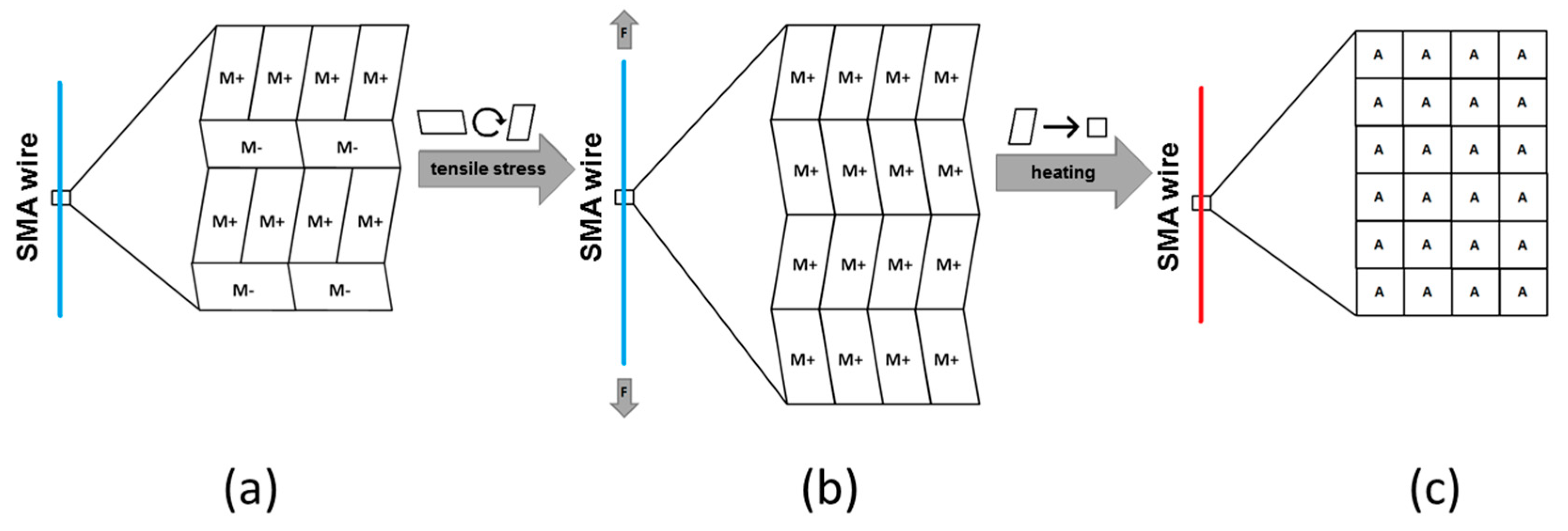
10]. The martensitic phase is characterized by the fact that it can occur in different orientations. In a two-dimensional view, it can be distinguished into M+ and M− (
Figure 1a). A quasi plastic deformation in the martensitic phase can be imagined as a flipping of the individual orientations [
9]. As a macroscopic consequence, SMA wires elongate by applying an external tensile force, since the M− oriented martensite crystals flip in M+ orientation at the microscopic level, whereby only the M+ orientation exists (
Figure 1b). If the wires are heated, they shorten due to the transformation into austenite (
Figure 1c).
The technically simplest and most feasible way to heat an SMA wire is to apply current to it. The electrical energy is converted into thermal energy, resulting in mechanical forces and movement [
12]. SMA wires are ideal for small, lightweight actuator systems because of their very high energy density in a range of
[
7,
12].
2. Functional Principle
The challenge was to achieve a large rotary motion from the stable linear stroke of 4% of an SMA wire. Besides, the actuator must be compact and have a bidirectional motion of at least 90°. For resetting the actuator, springs should be omitted, which is why an agonist-antagonist system was chosen. This has the advantage of enabling fast rotation in both directions. To guarantee the functionality of an antagonistic SMA system, the condition of the wires must be taken into account when installing them. In this case, the antagonistic wires were installed in austenitic state and the agonistic wires in the martensitic state.
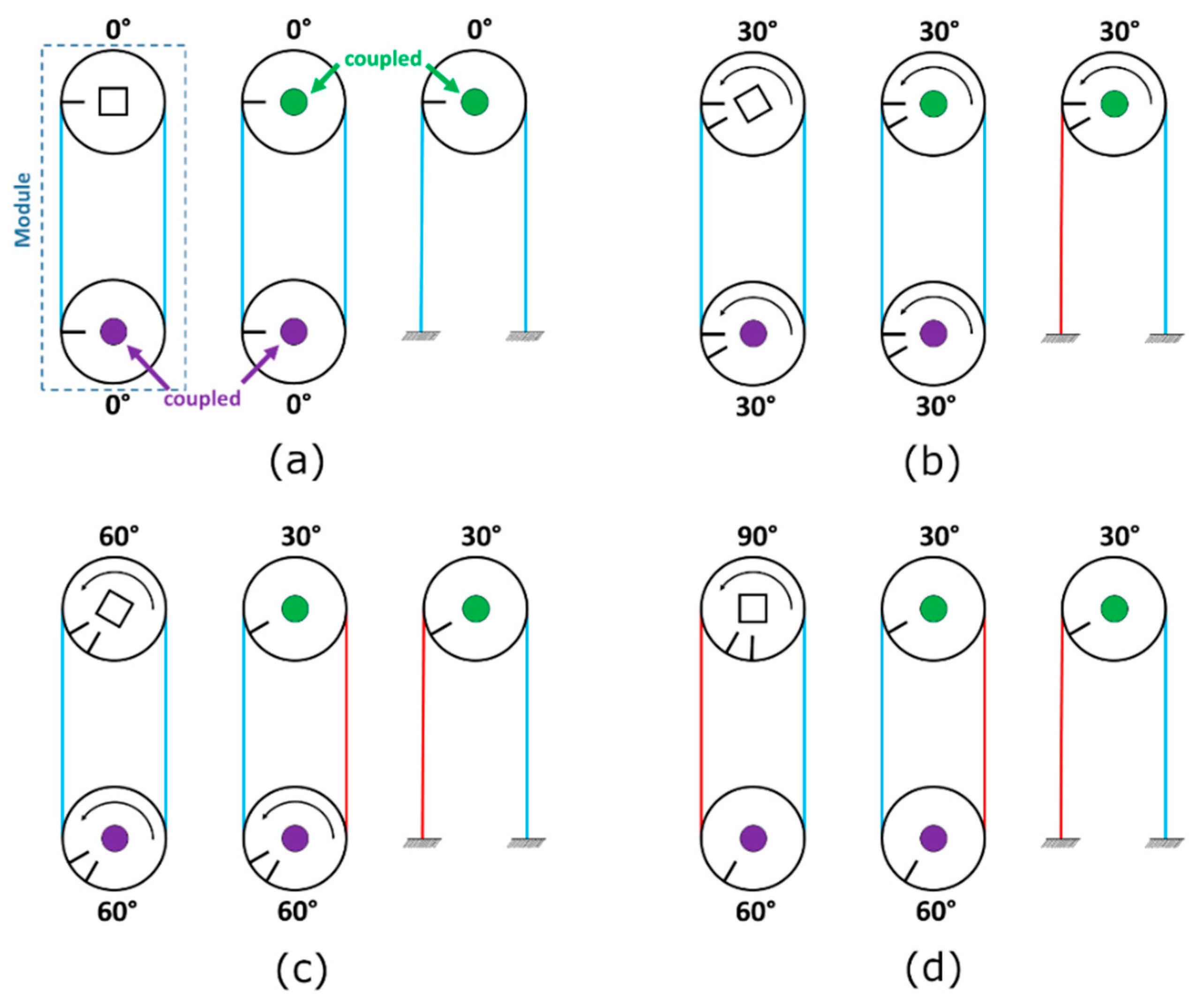
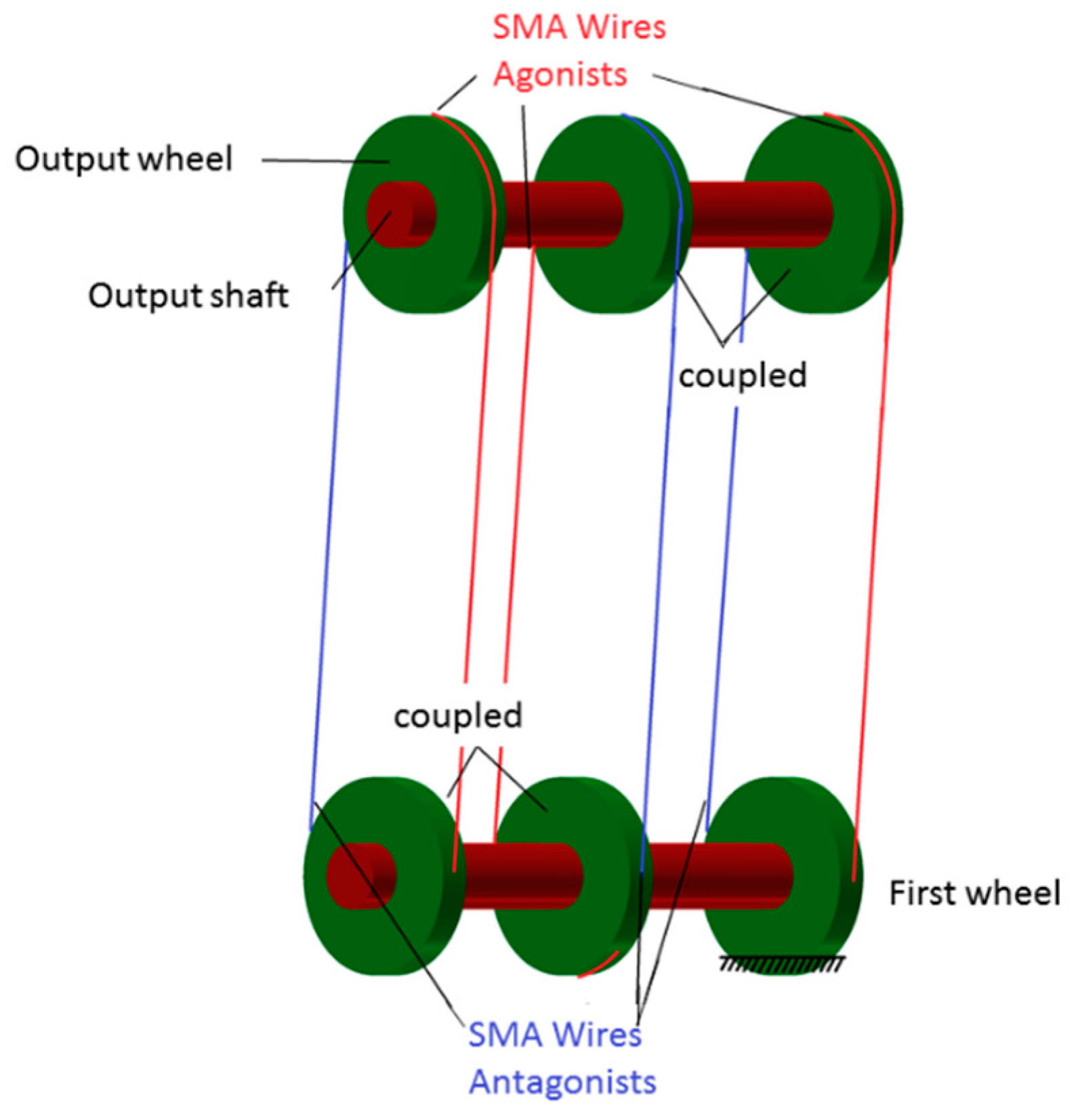
Figure 2 shows the functional principle using an exemplary 90° rotation, where each wire-wheel pair (module) generated 30°. The blue or purple dots in the wheels indicate mechanically coupled wheels. The color of the wires indicates whether a wire was activated (red) or not (blue).
Figure 2a shows the starting position at 0°.
Figure 2b shows the activation of the first wire, which caused the wheel in the upper right corner to rotate by 30°. Due to the mechanical coupling, the other wheels would be forced to rotate by 30° as well. Afterward, the second wire was activated (
Figure 2c), while the first wire remained activated. This resulted in another 30° rotation for the coupled wheels on the bottom shaft causing the output wheel to rotate by a total of 60° now. Finally, the third wire was activated (
Figure 2d), while the previous wires were still activated. This caused the output shaft to rotate by another 30°, which resulted in a total rotatory angle of 90°. The output wheel was mechanically coupled with the output shaft, while the remaining wheels could rotate without rotating the shafts. Therefore, only the output wheel could transmit a moment to the shaft. The first wheel on the lower shaft was fixed to serving as a locating bearing.
Figure 3 illustrates these interconnections. To save space, the modules were stacked on top of each other. Resetting the actuator to the initial position worked with the same principle.
The realized concept for generating a rotary motion was based on the principle that individual wire-wheel pairs, each causing a small rotation, add up to a large rotation. This also had the advantage that an incremental movement in mechanically defined steps was possible without the need for a control system. The movement was easily scalable by additional modules. Furthermore, angle and drive torque could be independently adapted to the application. If a larger torque was required, the radius of the wheels needed to be increased. On the other hand, adding additional modules resulted in a larger maximum rotary angle if desired. The concept allowed only a limited total rotation angle, depending on the limited rotation of each module.
3. Design
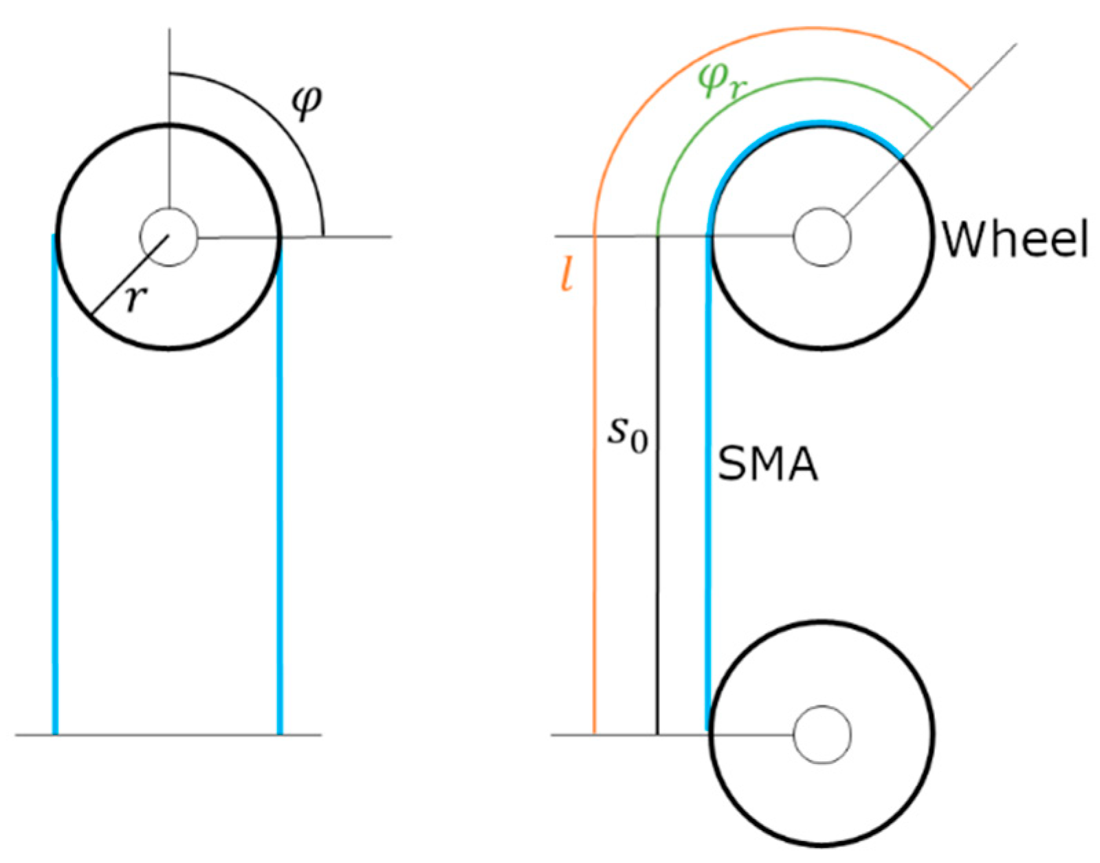
The actuator should have a rotation angle of at least 90° in steps of 30° and should not be larger than 200 × 60 × 30 mm. Since SMA wires are limited in stroke, the martensite wire length, required to achieve the desired angle per module, was calculated. The arc length
is given by the following formula:
Considering the 4% stroke of the SMA wire, the arc length could also be calculated as:
Equations (1) and (2) give the total length
depending on the rotation angle
and the wheel radius
(
Figure 4):
Assuming a rotation angle of
and a wheel radius of
, the wire length results in:
Since the total wire length was now known and had to extend from one shaft to another, the distance between the shafts needed to be defined. The distance had to be selected so that the wire could still be wound around the wheel and fixed at a minimum required angle (
Figure 4). To define this required angle
at which the SMA wire needed to be fastened to the wheel for construction purposes, the following calculation was used:
with a distance between the wheels of, for example,
Thus, to achieve the desired angle per module, a wire had to be passed from the lower wheel to the upper wheel and needed to be attached to it at a minimum angle of
(
Figure 4).
The design was based on the minimum wire length and dimensions used in the previous calculation. However, it should not be larger than necessary.
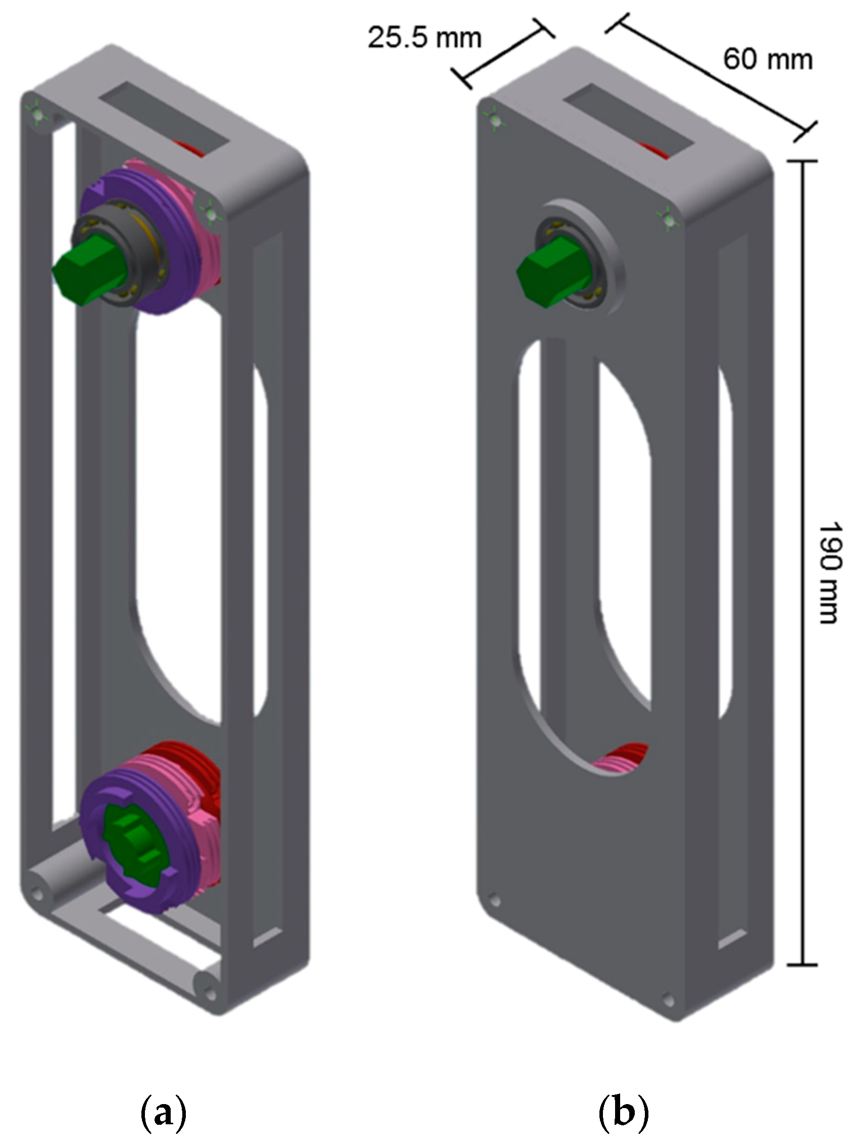
Figure 5 shows the CAD model of the final prototype. The shafts were shown in green. The individual modules were arranged into three levels, which were colored in purple, pink, and red. Each level contained two wheels, which were connected with the SMA wires. The ball bearings, shown in dark grey, minimized the friction between wheels and shafts. To optimize the rotation performance, the shafts were made of stainless steel, so that an optimum tolerance pairing could be achieved. 3D printed shafts proved to be improper. The remaining designed parts were produced using 3D printing. The SMA wires were mechanically and electrically fixed and contacted via a screw connection.
4. Electronics
To keep the actuator compact, the electronics were designed to fit on the housing of the actuator. Since the actuator specifications might vary for different applications, different SMA wire diameters might be needed, as well as a different maximum rotational angle might be desired. As a consequence of different maximum angles, the number of modules could vary. To build easily exchangeable electronics and to be able to react flexibly to different specifications, two circuit boards were developed. One for communication with the environment and one for controlling the SMA wires. The communication board received commands from the user and informed the control board which wires were supposed to be activated. The advantage of this setup was that the communication board on the hardware side could always remain the same, while the hardware on the control board only had to be adapted to the respective actuator depending on the application specifications. On the software side, both boards would have to be adapted to ensure error-free communication between the two boards. The user could control the actuator via USB or Bluetooth. The two boards are explained in detail below.
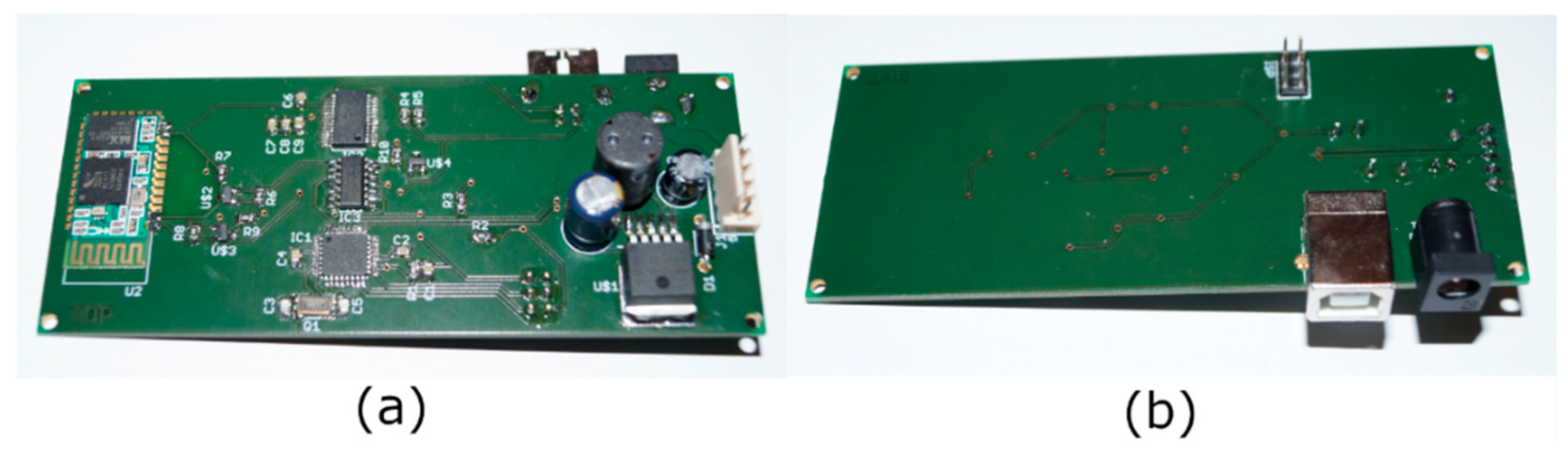
The communication board consisted of a microcontroller that processes the user’s commands, interprets, and sends them to the control board via IIC. It had USB and Bluetooth to receive the commands. By default, Bluetooth was used to receive the commands, and connecting a USB cable would automatically switch to the USB interface using an IC as a logic switch. A voltage regulator provided the required supply voltage for the different ICs.
Figure 6 shows the top and bottom side of the finished communication board.
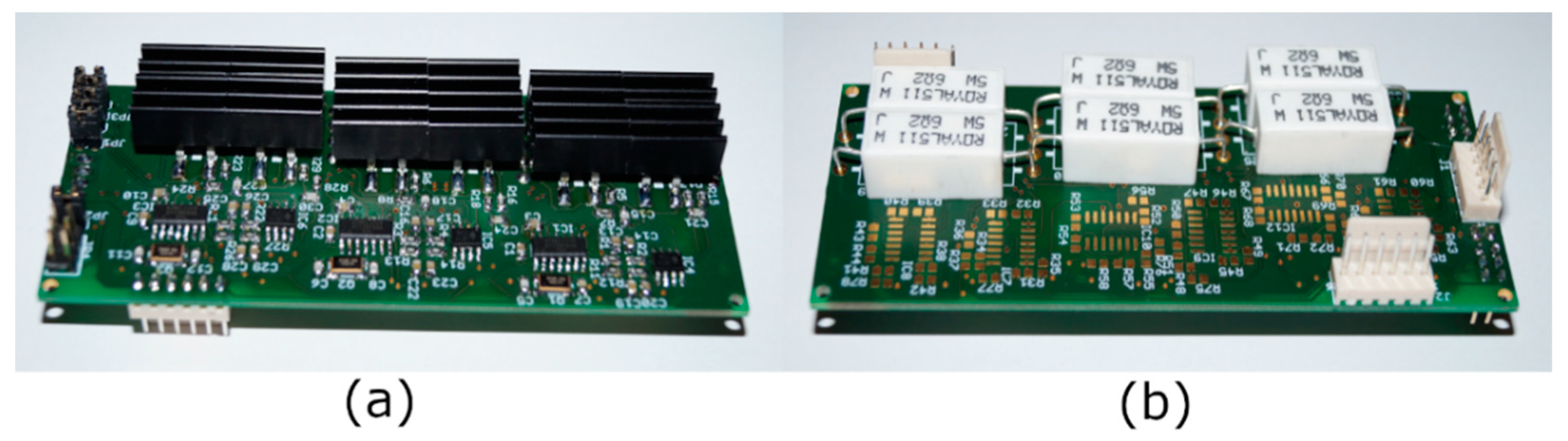
Below, the development of the control board is explained. This board contained a pole pin header for the different supply voltages, 5 V for the supply of the microcontrollers, on the one hand, and 12 V for the supply of the remaining hardware and the SMA wires, on the other hand. Besides, the board consisted of three microcontrollers connected to the IIC bus, which controlled the individual wires via voltage-controlled current sources. A total of six of these power sources were installed. Thus, one microcontroller and two power sources were installed per module. If the number of modules was changed, only this had to be adapted accordingly, while no changes were necessary on the communication board. Signal conditioning was implemented on the board to be able to, for example, adapt the voltage drop of each SMA to the input voltage range of the analog-to-digital converter (ADC), integrated into the microcontroller. The top and bottom of the control board are shown in
Figure 7.
5. Measurements
This section describes the measurement and evaluation of the prototype. First, the measuring principle is explained, followed by a discussion of the presented measurement results.
5.1. Mechanical Characterization
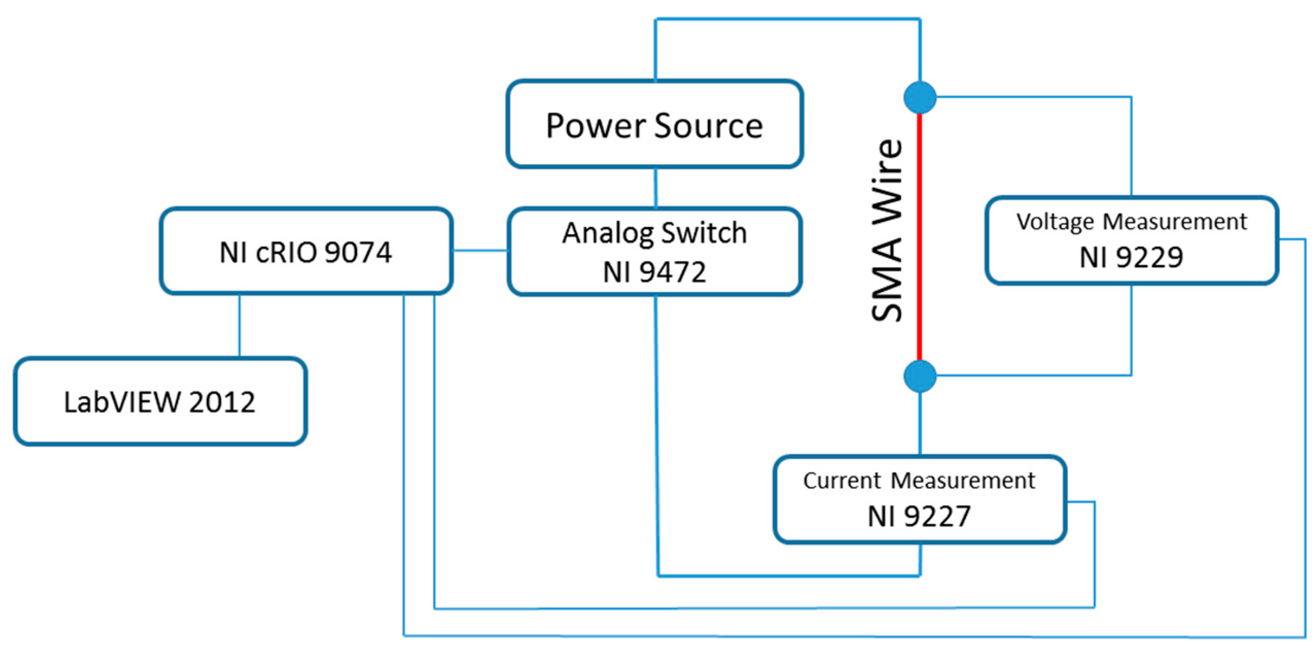
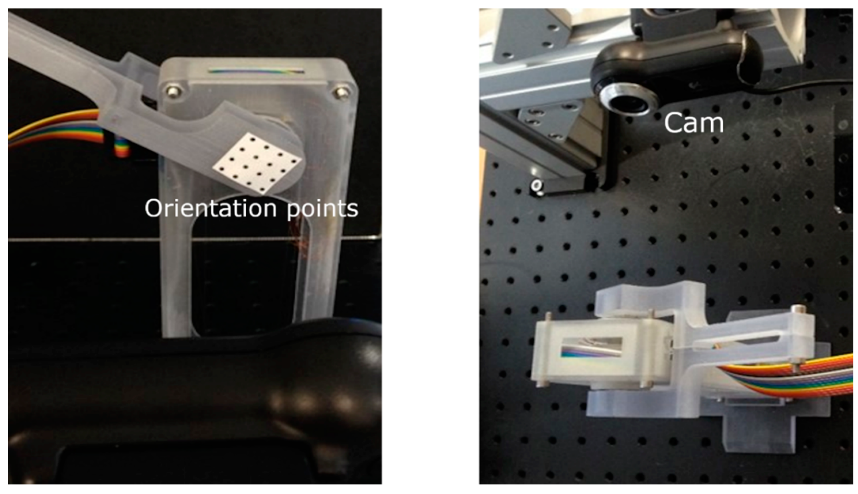
The measurement and control setup, illustrated in
Figure 8, was based on components from National Instruments and uses LabVIEW to control the experiments and record the data. The analog switch NI 9472 applied the voltage from the power supply to the wires. The voltage drop across the wire was measured by a NI 9229 voltage measuring module mounted parallel to the wire. The current flowing through the wire was measured by a NI 9227 current measuring module mounted in series with the wire. The measurement results were transmitted to the PC via a NI cRIO 9074 control unit.
To measure the covered angle, a one-point tracking method was used. Using orientation points on the output shaft, a MATLAB program was used to evaluate the video of the rotational motion and thus determine the rotation angle.
Figure 9 shows the camera setup and the orientation points on the output shaft.
The SMA wires were heated by using constant electrical power.
Figure 10 shows the first measurements of the electrical power over time as system input and the rotation angle of the actuator over time as system output. Every 2 s another agonist wire was activated with a power of 4.5 Watt. The individual steps in the plot showing the rotation angle over time were a result of the individual activations of the wires. Each step showed an angle change of about 20°. These intermediate positions resulted from the design of the actuator and could, therefore, be achieved without additional control. After reaching the maximum angle after 13 s, the input power was switched off. As a result of this, the wires cooled down, leading to an angle deviation caused by the elastic deformation of the antagonistic wires, which later relaxed again.
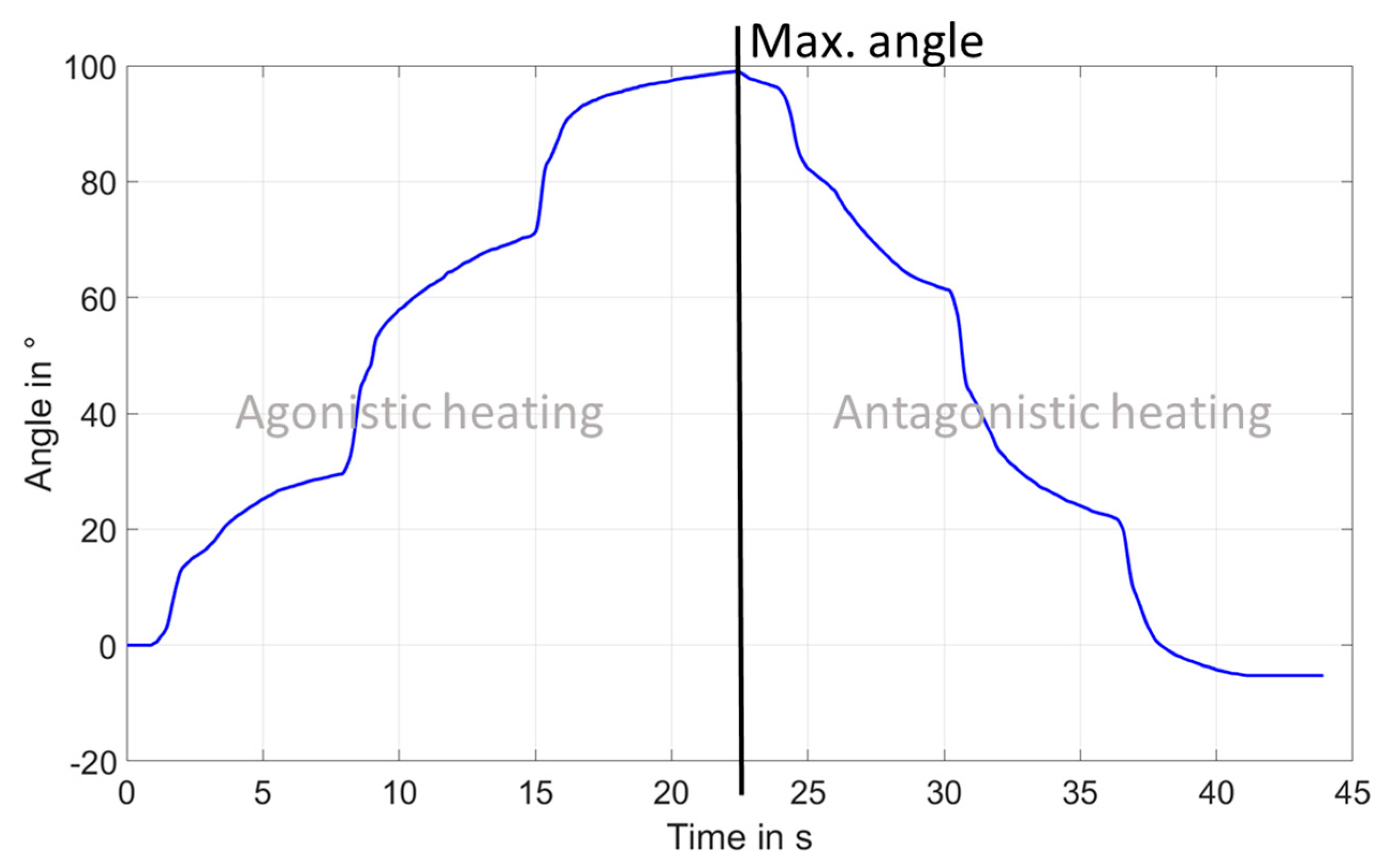
This prototype did not reach the desired maximum rotation angle of 90°. After optimization of the wire installation process and some smaller design improvements, the result of the rotational movement is shown in
Figure 11. Each step in both directions was about 30°. The maximum rotational movement was about 100°. Reaching the maximum rotation angle at about 22 s, the electrical power applied to the SMA wires was switched off, and the opposing wires were now being heated. This resulted in a corresponding movement in the opposite direction. Since the position at 0° was a resting position while no external or internal forces were applied to the system, heating the antagonistic wires resulted in a negative angle.
5.2. Electrical Characterization
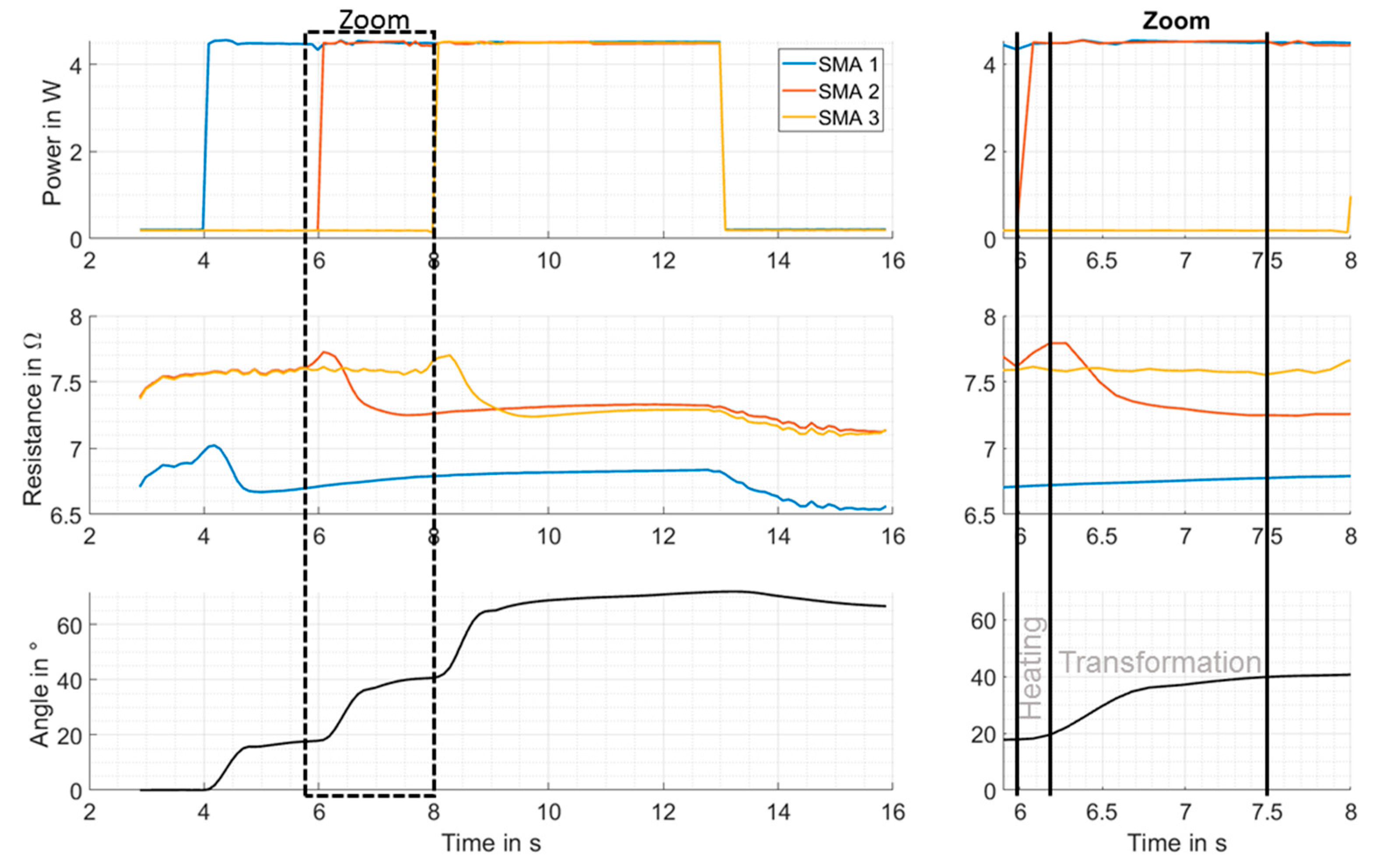
In addition to the angle measurement, the electrical resistance
was calculated by dividing the measured voltage drop over the SMA wire by the measured current flowing through the SMA wire (see
Figure 12).
Due to its design, SMA1 was shorter than the other SMA wires, resulting in a lower basic resistance. If an SMA wire was being heated, the resistance first increased due to the positive temperature coefficient of metals, as shown in the zoom plot of
Figure 12 from 6–6.2 s. The following decrease of the SMA resistance between 6.2 s and 7.5 s was a consequence of the phase transformation from martensite to austenite, accompanied by a starting rotational motion. After 7.5 s, the resistance increased again because of the end of the phase transformation combined with ongoing heating of the SMA wire. As a result, the rotation angle remained constant. This large resistance change could be used to determine the position of the actuator because of a correlation between the decreasing resistance signal and the rotational angle (see
Figure 12, Zoom). This correlation enabled detecting the mechanically given intermediate positions at 30°, 60°, and 90° by identifying local minima in the resistance signal, as well as reaching and controlling any desired position using a model-based control. The basic principle of antagonistic SMA wire systems and their controlling abilities are shown in [
14].
6. Conclusions and Outlook
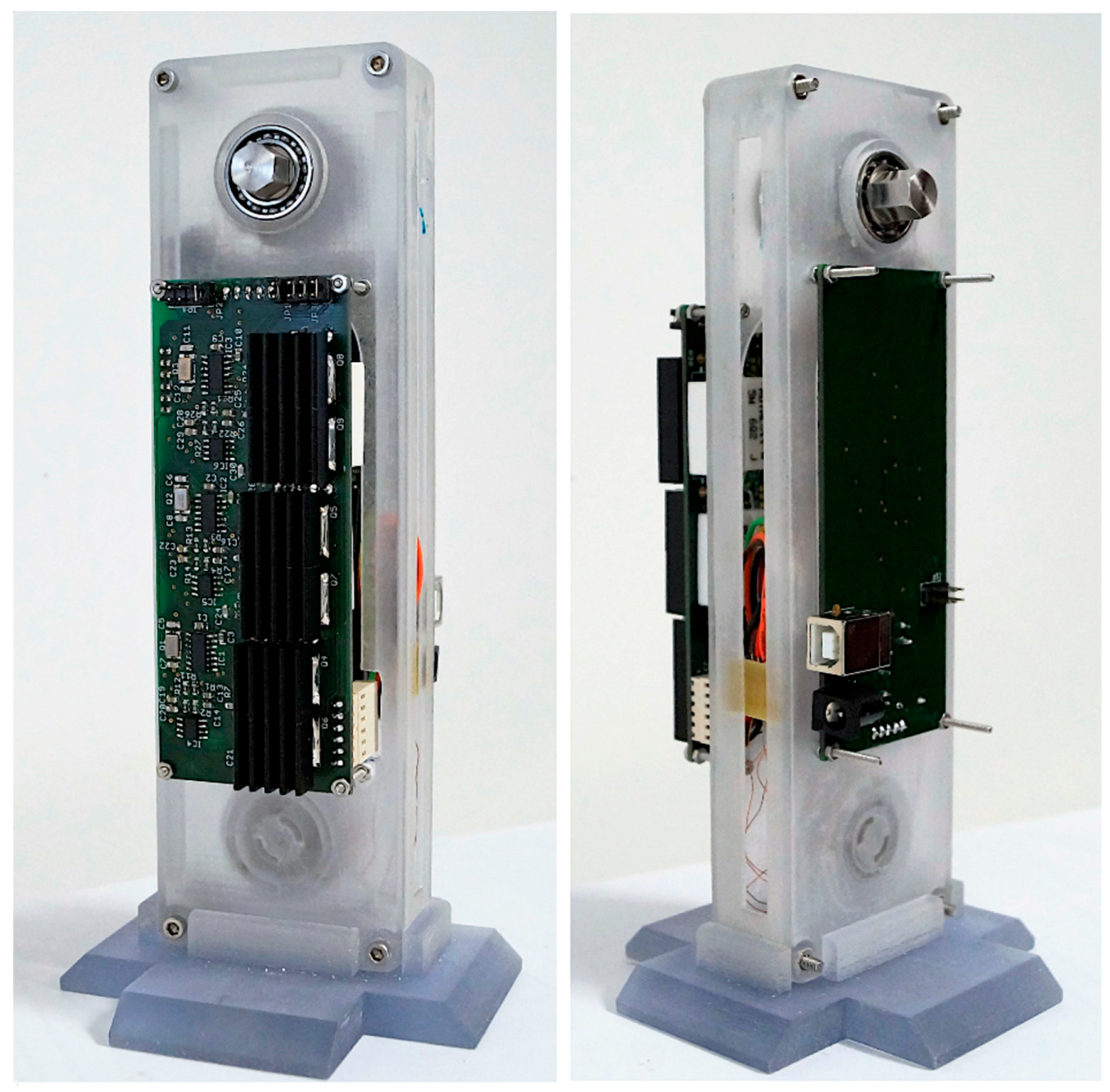
The purpose of this article was to present the prototype of a rotary actuator based on SMA wires. The implemented actuator concept allowed scaling the output torque as well as the maximum rotation angle. Depending on the design, a desired maximum rotation angle could be achieved with different combinations of the number of the modules and the rotation angle of each module. To achieve, for example, a maximum angle of 90°, you could either choose three modules with a 30° rotation angle each or six modules with a 15° rotation angle each. The functionality of the actuator principle was validated by measuring the rotation angle of the actuator using a 3D printed prototype. The modular design of the electronics allowed for a flexible adaption to the mechanics, requiring minimal hardware changes. The electronics consisted of two separate boards, one communication board, which represented the interface between the actuator and the user, and a control board, which controlled the individual SMA wires. This allowed the communication board to remain the same for different numbers of modules, and only the control board had to be adapted to the respective number of used SMA wires. To be able to use the self-sensing effect of the SMA wires, the relevant current and voltage measurement circuits, which were needed to determine the resistance of the SMA wire, were already implemented. The self-sensing effect could be used for an angle control of the actuator or failure monitoring of the system. A next step would be an additional validation of the generated torque. The final prototype, including the two circuit boards, is shown in
Figure 13.
Author Contributions
R.B. was responsible for concept development, design and construction of the prototype including electronics, as well as its validation. P.M. and S.S. were involved in concept development, supervision and consulting.
Funding
This research received no external funding.
Conflicts of Interest
The authors declare no conflict of interest.
References
- Nalbach, S.; Motzki, P.; Seelecke, S. SMA-based hydraulic switching valve. In Proceedings of the ASME Conference on Smart Materials, Adaptive Structures and Intelligent Systems (SMASIS), Colorado Springs, CO, USA, 21–23 September 2015; Volume 3, p. V002T04A006. [Google Scholar]
- Motzki, P.; Kunze, J.; York, A.; Seelecke, S. Energy-efficient SMA vacuum gripper system. In Proceedings of the ACTUATOR 16—15th International Conference on New Actuators & 9th International Exhibition on Smart Actuators and Drive Systems, Bremen, Germany, 13–15 June 2016; pp. 526–529. [Google Scholar]
- Motzki, P.; Holz, B.; Simone, F.; Seelecke, S. Formgedächtnislegierungen in Applikationen der Greif-und Handhabungstechnologie—Shape Memory Alloys in Applications of Gripping-and Material-Handling-Technology. In Proceedings of the Fachtagung Mechatronik 2015, Dortmund, Germany, 12–13 March 2015; pp. 55–60. [Google Scholar]
- Motzki, P.; Goergen, Y.; York, A.; Seelecke, S. Reconfigurable SMA end-effector for material handling. In Proceedings of the ACTUATOR 16—15th International Conference on New Actuators & 9th International Exhibition on Smart Actuators and Drive Systems, Bremen, Germany, 13–15 June 2016; pp. 522–525. [Google Scholar]
- Dynalloy Inc. Technical Characteristics of Flexinol Actuator Wires; Dynalloy Inc: Irvine, CA, USA, 2016. [Google Scholar]
- Seelecke, S.; Müller, I. Shape memory alloy actuators in smart structures: Modeling and simulation. Appl. Mech. Rev. 2004, 57, 23. [Google Scholar] [CrossRef]
- Janocha, H. Unkonventionelle Aktoren—Eine Einführung; Oldenburg Verlag: München, Germany, 2010. [Google Scholar]
- Lagoudas, D.C. Shape Memory Alloys; Springer: Boston, MA, USA, 2008; Volume 1. [Google Scholar]
- Bäker, M. Funktionswerkstoffe Physikalische Grundlagen und Prinzipien; Springer Vieweg Verlag: Wiesbaden, Germany, 2014. [Google Scholar]
- Just, E. Entwicklung Eines Formgedächtnis-Mikrogreifers. Ph.D. Thesis, Fakultät für Maschinenbau der Universität Karlsruhe, Karlsruhe, Germany, 2001. [Google Scholar]
- Britz, R. Entwicklung eines skalierbaren Rotationsaktors auf Basis von Formgedächtnislegierungsdrähten. Master’s Thesis, Saarland University, Saarbrücken, Germany, 2016. [Google Scholar]
- Schiedeck, F. Entwicklung Eines Modells für Formgedächtnisaktoren im Geregelten Dynamischen Betrieb. Ph.D. Thesis, Produktionstechnisches Zentrum Hannover, Garbsen, Germany, 2009. [Google Scholar]
- Britz, R.; Motzki, P.; Seelecke, S. Skalierbarer Rotationsaktor auf Basis von Formgedächtnislegierungsdrähten. In Proceedings of the Fachtagung Mechatronik 2017, Dresden, Germany, 9–10 March 2017. [Google Scholar]
- Furst, S.J.; Crews, J.H.; Seelecke, S. Stress, strain, and resistance behavior of two opposing shape memory alloy actuator wires for resistance-based self-sensing applications. J. Intell. Mater. Syst. Struct. 2013, 24, 1951–1968. [Google Scholar] [CrossRef]
© 2019 by the authors. Licensee MDPI, Basel, Switzerland. This article is an open access article distributed under the terms and conditions of the Creative Commons Attribution (CC BY) license (http://creativecommons.org/licenses/by/4.0/).


