Abstract
Nowadays, the development or improvement of soft actuation mechanisms is a crucial topic for the achievement of dexterous manipulation using. Then, a primary target of research is the design of actuation and driving devices. Consequently, in this paper, we introduce a soft driving epicyclical mechanism that mimics human muscle behavior and fulfills motion requirements to achieve grasping gestures using a robotic finger. The prototype is experimentally assessed, and results show that our approach has enough performance for the implementation in grasping tasks. Furthermore, we introduce the basis for a new soft epicyclical mechanism merger with shape memory alloys to allow active stiffness control of the mechanism.
1. Introduction
The task of designing or improving a robotic hand (to replicate the grasping capabilities and the kinematic functionality of the human hand) involves the consideration of high-complexity sensory and motor functions. The literature (e.g., [1]) shows that some robotic hands designed for research purposes have provided solutions for the domain of prosthesis. However, the actual state of the art shows that the requirements of dexterous manipulation—regarding mechanisms, actuation, and kinematic properties—have not been fulfilled [2]. One important consideration for developing actuation mechanisms concerns the actuation level, robotic hands present in the current state of the art could be classified mainly into three categories (see Table 1):

Table 1.
Summary of robotic hands and its type of actuation.
- Under-actuated;
- Fully actuated;
- Over-actuated.
Type of actuation is based on the number of actuators used to drive a joint. For instance, a robot having three rotational joints, each one provided with one degree of freedom, could be driven by three actuators (one per joint)—in that case, the robot is fully-actuated. When the number of actuators is bigger than the number of joints, the robot is over-actuated. Finally, when the number of actuators is lower than the number of joints, two or more joints must be driven by only one actuator, that case is the under-actuated scenario.
Regarding functional requirements, Ramirez Arias [22] proposes a study of three critical aspects of the human hand: The kinematics, the functionality, and the dynamics. Concluding that for the development of a prosthetic hand, each finger must achieve the following:
- Have an active flexion in the range of in the MCP, PIP, and DIP joints (see Figure 1) of the finger;
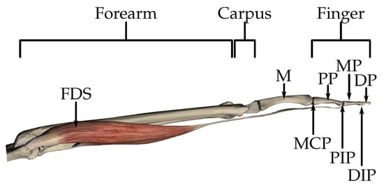 Figure 1. Main joints and bones of human upper limb, and Flexor Digitorum Superficialis (FDS) muscle, acting over a finger (M: Metacarpus, PP: Proximal phalanges, MP: Medial phalanges, and DP: Distal phalanges).
 - Perform force in the interval NN];
- Achieve operating frequency in the interval HzHz];
- Propose an actuation system based on viscoelastic behavior of human muscle.
Concerning the definition of criteria to qualify the muscle’s behavior, Hill’s mechanical equivalent models are more suitable due to the use of equivalences between biological and mechanical elements. Classical Hill’s model was established by Hill [23], and consists of an arrangement of elastic elements that are used as descriptors of the muscle’s elastic behavior. Figure 2 shows the Equivalent model, based on the description given by Hill [24].
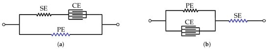
Figure 2.
Equivalent Hill model: (a) Parallel and (b) serial.
Over the years, several variations of the Hill model have been proposed, adding mechanical elements and considerations to qualify the muscle’s behavior. In this paper, we choose the model proposed by Ramirez Arias [22], which mainly considers two significant variations with respect to classical models: The pennation angle , which influences the kinematics and the force during movements; and a parallel damper-spring element, representing the tendon to describe the muscle behavior accurately. The complete model, presented in Figure 3, is composed by:
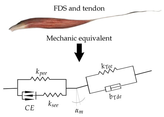
Figure 3.
Retained Hill-based model proposed by to describe the behavior of Flexor Digitorum Superficialis (FDS) muscle.
- , the contractile element;
- , the parallel elastic element of the muscle;
- , the muscle’s serial elastic element;
- , the tendon’s elastic element;
- , the tendon’s damping element;
- , the pennation angle.
A classic actuation system and a drive mechanism can easily fulfill motion, force, and frequency requirements. However, a rigid device is not able to mimic the required viscoelastic behavior. Consequently, the first constraint for developing an appropriate mechanism is the inclusion of soft materials in the machinery design [25], merging the usage novel fabrication technologies as 3D printing [26,27], which can also lead to the development of soft robots.
Therefore, in this paper, we introduce the design of a biomimetic driving mechanism, aiming to reproduce the viscoelastic behavior of the human muscle, meanwhile satisfying kinematic, dynamic, and static requirements. The device considers the operating principle of the epicyclical mechanism merged with elastic elements.
2. Soft Epicyclical Mechanism
According to state of the art, developed by Ramirez Arias [22]:
- The most used drive mechanism is based on tendons;
- The mass of a prosthetic hand must be under 600 g;
- The number of actuators must be reduced, but the number of the degree of freedom (DoF) must be as high as necessary to perform the prehension;
- An electric actuator is a right approach, but needs to be complemented with soft elements to achieve the desired behavior.
In the following, we introduce the prototype of the so-called robotic finger ProMain-I, which uses a new tendon-driven mechanism (to provide flexibility in the articular joints) and takes into account human hand requirements.
The adduction–abduction of metacarpophalangeal (MCP) joints play an essential role in preparing the hand for grasping. Moreover, the finger’s flexion–extension movements are more significant to perform the hand grasping gesture. Consequently, if the fingers are correctly placed for grasping, adduction–abduction of MCP joints are not required, and the prosthesis can be simplified without impacting prehension ability. Thus, the proposed finger prototype is only endowed with flexion and extension on metacarpophalangeal (MCP), Proximal Interphalangeal (PIP), and Distal Interphalangeal (DIP) joints.
In order to develop the tendon-based ProMain-I finger, an early “alpha” prototype of the robotic finger is introduced. The “alpha” finger prototype is a bio-inspired tendon-driven finger [28,29,30] composed of three joints: The metacarpophalangeal (MCP), the proximal interphalangeal (PIP), and the distal interphalangeal (DIP). All the joints have one DoF to perform flexion and extension. The finger is controlled by only one actuator, and the drive mechanism uses two tendons for transmitting motion, one for the flexion and one for the extension, as shown in Figure 4. Considering that the tendons are fastened to the motor pulley and the fingertip, the clockwise rotation of the actuator produces the flexion; and the counterclockwise rotation provides the extension.
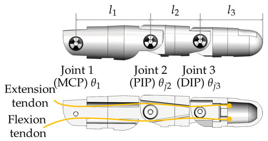
Figure 4.
Early “alpha” prototype of the robotic finger.
The finger is endowed with two tendons, each one directly fastened to the input pulley and the fingertip (see Figure 5). Consequently, the main drawback of the alpha prototype was the inability to handle sub-actuation relations by changing pulleys ratios. Moreover, the finger movement was dominated by external conditions and experiments had a low degree of repeatability. Nevertheless, due to the under-actuation, the rotation angle of the PIP and DIP joints are linked with the rotation angle of the MCP joint.

Figure 5.
Early “alpha” prototype of the robotic finger.
The relations between joint angles are calculated using experimental measures [29]. As a result, the obtained relations between angles are and , where is the MCP joint angle, is the PIP joint angle, and is the DIP joint angle. Furthermore, the parameters , , and are the lengths of the proximal, medial, and distal phalanges, respectively, as shown in Figure 5.
The analysis carried out using experimental data, issued from the “alpha” prototype of the robotic finger, gives us valuable and relevant information for the improvement of the finger’s mechanism and actuation systems and lets us define the following functional requirements [29,30]:
- Higher stiffness into the MCP joints;
- A fixed mechanical relation between the proximal and metacarpal joints, and between the distal and metacarpal joints.
Those improvements are introduced in the ProMain-I finger prototype.
The new driving mechanism is inspired by the epicyclical gear train, which is typically composed of two gears (one fixed and one mobile) whose centers are attached through a rigid link so-called carrier. The rotation of the carrier then creates a revolve of the mobile gear center around the fixed gear. As a result, due to the mechanical link between gears, a rotation is provided on the mobile gear. Furthermore, the rotation amount of the carrier can be different from the rotations of the mobile gear, which is controlled by the gears relation. Figure 6a exemplary shows an epicyclical gear train (whose gears are labeled with white circles to follow relative rotations) in which the carrier has rotate and the mobile gear .
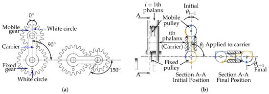
Figure 6.
(a) Epicyclical mechanism, left side is the initial state and right side is the final state; and (b) soft epicyclical mechanism, left side is the initial state of the section A-A and right side is the final state.
Consequently, for our driving mechanism, we proposed a soft epicyclical mechanism in which:
- The finger’s phalanges replace the carrier;
- The gears are replaced by two slotted pulleys;
- The mechanical link is guaranteed by two crossed flexible wires, henceforth, tendons.
Figure 6b shows the scheme of the driven mechanism, in which blue line represents the tendon that drives clockwise rotation; and the yellow line depicts the tendon used to produce counterclockwise rotation—clockwise and counterclockwise rotations are assumed regarding the figure orientation. The i-th phalange of the finger begins in a vertical position, then, after a rotation, it reaches a horizontal position. The center of the mobile pulley orbits around the fixed pulley, and due to the effect of the tendons, the mobile pulley rotates. As a result, a rotation is produced in the ()-th phalange, which is fixed to the mobile pulley. If the mobile pulley gets blocked during rotation, the driving tendon is constrained in tension, so that the elasticity of the tendon’s material depicts the stiffness of the joint.
The proposed soft epicyclical mechanism is used to transmit motion between the MCP joint and the PIP joint, and between the PIP joint and the DIP joint. As a result, two groups of tendons are used—each group is composed of one flexion tendon and one extension tendon. Thus, Promain-I finger motion consists in the flexion and extension. Tendons are fabricated in 0.3 mm diameter fibers of Nylon 6, which, by Young’s modulus, is 2.4 GPa. During the assembly of the prototype, tendons are fastened to pulleys in such a way that pre-tension is 95 Mpa, with a maximal base strain of 4%.
From a qualitative point of view, the elastic behavior of those elements allows us to mimic human muscle behavior. Furthermore, the same effect is used to reproduce the elastic behavior of human tendons presented in Section 1.
The damping element , introduced in Section 1, is used to describe more accurately the muscle behavior, avoiding undesired oscillations. In this case, considering that no oscillation is present, we consider that the element is embedded in the global behavior of the soft epicyclical mechanism. The following Figure 7 shows the equivalence between the proposed mechanism and the Hills-based muscle model.
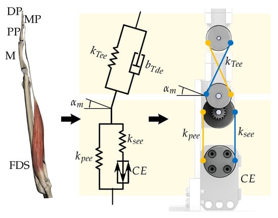
Figure 7.
Parallel between soft epicyclical mechanism and the Hills-based muscle model.
Following anthropomorphic requirements, the bio-inspired robotic finger ProMain-I [31] finger prototype is composed of three phalanges (proximal, medial, and distal)—which are linked through Metacarpophalangeal (MCP), Proximal interphalangeal (PIP), and distal interphalangeal (DIP)—all joints have one degree of freedom (DoF) to perform flexion and extension. Nevertheless, the angle relationship of the finger’s joints is settled by pulleys ratio. The finger is controlled by only one servo motor, an XL-320 Dynamixell ™. Hence, the medial (MP) and distal (DP) phalanges are driven by the proximal phalanx (PP) motion. The clockwise rotation of the actuator produces flexion; and the counterclockwise provides extension. The relation between the angles is , where is the MCP joint angle, is the PIP joint angle, and is the DIP joint angle. This relation between angles is established, manipulating the pulleys ratios, and is chosen to mimic the closure of the human hand—when the input angle reaches , the finger performs complete flexion. The ratio between length of phalanges is not required, and each length can be defined separately. In our case, we have chosen length trying to mimic human anthropomorphize.
Chassis, pulleys, and kinematic links (phalanges) of the finger prototype are manufactured from polylactic acid (PLA), using a 3D printer. In the following, we describe the assembly process. The robotic finger is under-actuated, hence, the movement is transmitted using only one servomotor, which is the active element and is linked to the MCP joint, see Figure 8. The XL-320 servomotor is linked to the proximal phalanx through the servomotor and input pulleys, which are connected by a tendon. The input pulley is directly attached to the PP using a gearbox composed of two gears (modulus 1) of 16 and 20 teeth, respectively. Likewise, the 1st fixed pulley is attached to chassis and is used as movement reference for the MP, in which PP is used as the carrier.
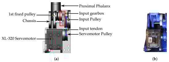
Figure 8.
(a) Input mechanism of Promain-I finger and (b) real view of the input mechanism of Promain-I finger.
The 1st fixed pulley (attached to chassis) is linked to the 2nd fixed pulley (attached to MP phalanx) through two tendons, and functions as movement reference for the epicyclical mechanism that drives MP phalanx (see Figure 9a). In this part of the finger, PP behaves as the carrier and MP as the driver. Likewise, the 3rd fixed pulley (attached to PP phalanx) is linked to the 4th fixed pulley through another set of two tendons, and acts as movement reference for the epicyclical mechanism that drives DP phalanx (see Figure 9b). In this second epicyclical mechanism, MP behaves as the carrier and DP as the driver.
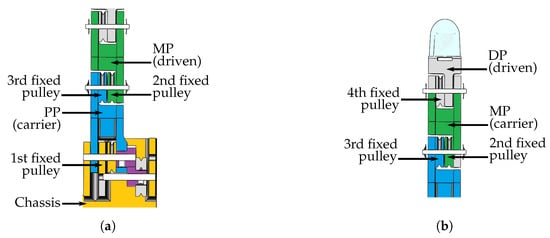
Figure 9.
Assembly of the finger, yellow represents chassis, blue represents PP phalanx, green represents MP phalanx, and gray represents DP phalanx. (a) Assembly of the PP and MP phalanges, in which PP is the carrier and MP is the driven and (b) Assembly of the MP and DP pahalanges, in which MP is the carrier and DP is the driven.
As can be seen in Figure 10a, the first epicyclical mechanism (composed by 1st and 2nd fixed pulleys, and the carrier PP) drives MP phalanx from an initial position, in which the finger is straight, until a final position in which angle between PP and MP phalanges is 90. Similarly, the second epicyclical mechanism (composed by 3rd and 4th fixed pulleys, and the carrier MP) drives DP phalanx from an initial position, in which the finger angle between MP and DP is 180, until a final position in which angle between PP and MP phalanges is 90, see Figure 10b.
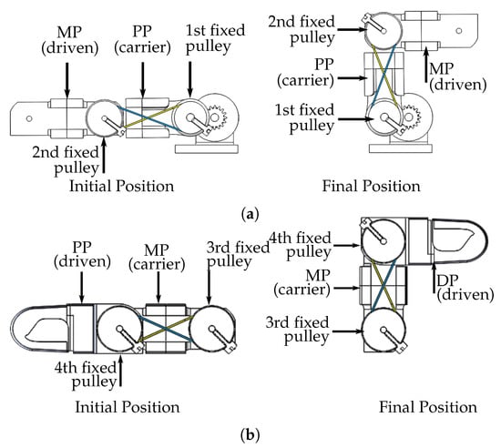
Figure 10.
Finger movement: (a) Movement of medial phalanx (MP) with respect to proximal phalanx (PP), left side is the initial position and right side is the final position; and (b) movement of MP phalanx respect to PP phalanx, left side is the initial position and right side is the final position.
The final prototype of the ProMain-I finger is endowed of three degrees of freedom, which are all driven only by the soft epicyclical mechanism. Concerning the dimensions of the prototype, Figure 11 shows the phalanges’ lengths. Likewise, it is essential to note that one unique aspect of soft actuators is the involvement of intrinsic passive mechanical dynamics [32], in our case this feature is accomplished by the addition of elastic links in joints, which comes from the equivalence between our actuation system and the human muscle. Considering that in our mechanism, all elastic materials used in joins have the same characteristics, constants , , and have the same value, which corresponds to the young modulus of the Nylon 6 (2.4 GPa).
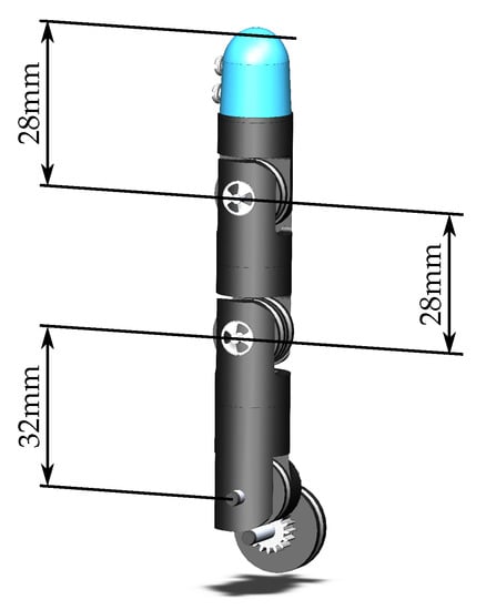
Figure 11.
Final prototype of the ProMain-I finger.
3. Materials and Methods
Considering that the finger prototypes are designed to perform flexion and extension in two dimensions, the kinematic is measured using a camera (Canon EOS 600D) pointing at a single-finger platform, shown in Figure 12, to track circular markers placed in finger joints and fingertip. The camera is positioned at 1 m from the finger prototype, and is adjusted to assure a pixel size of mm. The position accuracy (measured comparing several static images with a known value of length) is mm.
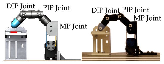
Figure 12.
ProMain-I finger test platform.
Images coming from the camera are processed to automatically recognize circular markers. The image analysis follows these five main steps (see Supplementary Materials):
- Crop image to extract the finger working area, see Figure 13a;
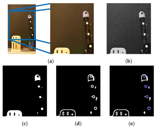 Figure 13. Automatic detection of finger joints an fingertip position: (a) Crop image; (b) gray scale; (c) binary image; (d) image edges; and (e) Hough transform.
 - Transform image into a gray scale, see Figure 13b;
- Shift image into a black and white scale, see Figure 13c;
- Detect image edges, see Figure 13d;
- Apply Hough transform [33] to find the circles positions in the image, see Figure 13e.
The image analysis delivers the position vectors of the joints, i.e., the vectors for the MCP joint of the finger, j, for the PIP joint, and for the DIP joint. Likewise, the vectors correspond to the fingertip positions. Considering that the movement is performed in the -plane, is always zero. The angles are measured, as shown in Figure 14, following the DHKK parameterization. DHKK parameters are defined to parameterize direct and inverse kinematics of robots composed of kinematic chains. The parameters can be described as follows [28]:
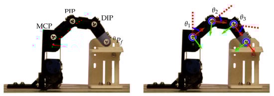
Figure 14.
Angles and final position measure.
- A rotation around ;
- A translation along ;
- A rotation around ;
- A translation along .
Formulation of direct kinematic is carried out merging DKKK parameters in the homogeneous matrix described in Equation (1), which formulates transformations between i-th and -th joints. Moreover, the kinematic of a robot composed of n joints is as presented in Equation (2). As a result, the matrix is a composition of the orientation of the end effector , and the position vector , as shown in Equation (3).
Thereafter, the following three vectors linking joints are defined:
- Vector between the MCP and PIP joints;
- Vector between the PIP and DIP joints;
- Vector between the DIP joint and fingertip.
These vectors are used to calculate rotation angles as
The first angle is calculated with respect to a reference positive vertical unitary vector —Figure 15 shows the vectors , the joints and fingertip position, and the location of .
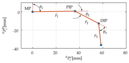
Figure 15.
Interpretation of measured kinematic data.
The proposed dynamic model uses the principle of virtual displacements and virtual work [29]. The equivalent dynamic model of the finger is shown in Figure 16, where , , and are, respectively, the weights of the proximal, medial, and distal phalanges, and are placed at the coordinates of the centers of mass , , and . is the applied force, which is equivalent to the reaction force, and is the input torque.
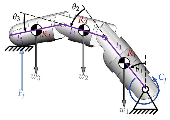
Figure 16.
Dynamic model of the robotic finger.
The virtual work is calculated for (1) the external forces (i.e., weight, applied force, and input torque) , where is the transposed external force vector and is the virtual displacement vector of the center of masses; and (2) the external forces contact point and the inertial forces (e.g., centrifugal forces) , where is the diagonal mass matrix composed of the masses and inertias , is the second derivative with respect to time of the coordinates vector representing the acceleration vector, and is the virtual displacement vector of the inertial frameworks.
The dynamic equilibrium is given by Equation (5), but, as in our model, the rigid bodies have movement restrictions and the displacements in the points where forces are applied aren’t independent—so, to solve the equilibrium equation it is necessary to separate the coordinates into dependent and independent coordinates.
In order to solve the equilibrium equation, considering the movement restrictions, it is necessary to separate dependent and independent coordinates. The separation is performed using the transformation proposed as
where is the Jacobian of dependent coordinates, is the Jacobian of independent coordinates, is the virtual displacement vector of the independent coordinates, and is the identity matrix. The equilibrium is thus written as follows:
Solving Equation (7), we obtain the input torque as a function of the force and the kinematic variables . The resulting expression is:
where
- ;
- ;
- ;
- ;
- ;
- ;
- ;
- ;
- .
4. Discussion
The experiment carried out with the ProMain-I finger aims to compare the expected rotation relations fixed in the soft epicyclical mechanism and the measured ones to verify the behavior of the finger. We follow the same experimental protocol introduced in Section 3. The calculated PIP and DIP joint angles, see Figure 17, shows an under-damped behavior for the PIP and the DIP joints when the finger gets in contact with the platform. This under-damped behavior was expected, considering that the actuation and driving mechanism is not endowed with the damper element. To evaluate the mean absolute error of the PIP and DIP joint angles, we compare the angle value obtained from the kinematic measure with the calculated angle value issued from the relation .
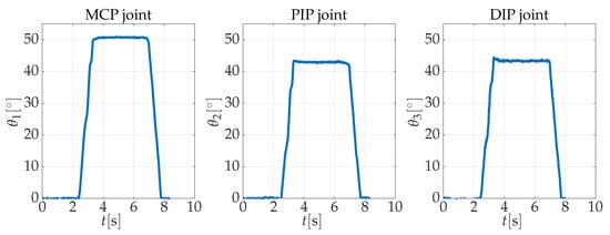
Figure 17.
Results of the position tracking of ProMain-I finger.
As a result, we find that the mean absolute error of the angle is , and the standard deviations is . With respect to the angle of the DIP joint, the mean absolute error is , and the standard deviations is . Moreover, the probability density function of PIP joint’s absolute error presents two peaks values—the first shows a concentration around zero degrees that corresponds to the error during free movement, and the second is the error when the finger gets in contact with the object. Likewise, the probability density function of DIP joint’s absolute error presents three peaks values, the first around zero degrees during free movement; and the two others during the contact phase. Both probability density functions are presented in Figure 18a,b, in which red lines represent the median, cross is the mean, a blue box represents the 25% and 75% quartiles and whiskers bound 9% and 91%. Presented results correspond to the analysis of 1566 samples, captured during 31.32 s of records, in which the robotic finger performs five trials of flexion–extension movement.
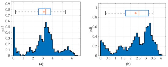
Figure 18.
Probability density function of: (a) absolute error; and (b) absolute error.
This error, present in the articular joint values and , is the result of the self-adaptability of the finger to objects during contact. This effect is the result of the low stiffens of tendons used in the soft epicyclical mechanism.
The required force must be expressed in terms of the equivalent torque that acts on the input pulley. The way of converting the required fingertip force into the corresponding active torque is described in the following. To calculate the required torque using the proposed dynamic model, it is necessary to know the vector , which corresponds to the dependent and independent coordinates of the robotic finger. The values and correspond to the position of the center of masses , and are calculated during the experiment.
Finally, applying the dynamic and kinematic models, we calculate the required input torque for a force in the range N N, which corresponds to the target force interval. The input torque must be in the interval Nmm Nmm]. Taking into account that the ProMain-I finger radius is 7 mm, the required force of the actuator must be in the interval N N]. Consequently, tendons mus support a stress in the interval MPa MPa]. Due to the combination of the epicyclical mechanism with the serial servomotor, the actuation system can perform up to 2.028 cycles/s. Consequently, in this study, we are not focused on the required frequency interval, which is much lower than the capacity of the actuation system.
Regarding finger capabilities for grasping, we have carried out several tests using the prototype in a platform, which places the fingers in opposition, guaranteeing the possibility to grasp different objects. Figure 19 shows exemplary grasping of: a pen, a tape, an apple, a bottle, and a coin.
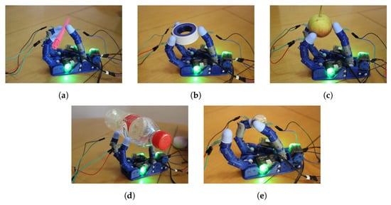
Figure 19.
Grasping of: (a) a pen, (b) a tape, (c) an apple, (d) a bottle, and (e) a coin.
Furthermore, under some particular conditions, the flexibility of the tendons requires being adapted to grasp objects in a more steady way. Taking into account that the addition of damper element in the tendon adds extra constraints to the soft behavior of the epicyclical mechanism, and considering the advantages of smart materials, we modify the driving mechanism by adding a Shape Memory Alloy (SMA) wire in parallel to flexible tendons to control joint stiffness during grasping. As a result, a new soft epicyclical tendon-driven actuation system based on SMA is proposed.
The soft epicyclical tendon-driven actuation system is also based on the proposed Hill’s muscle model, but the damper is substituted by an SMA wire in order to control the mechanism’s stiffness. As can be seen in Figure 20, the SMA wire is placed in parallel to the elastic tendon . During the operation, when the tendon is under a tension , a control stimulus (temperature increment) shifts the SMA wire to austenite phase, increasing the stiffness to recover the produced strain.
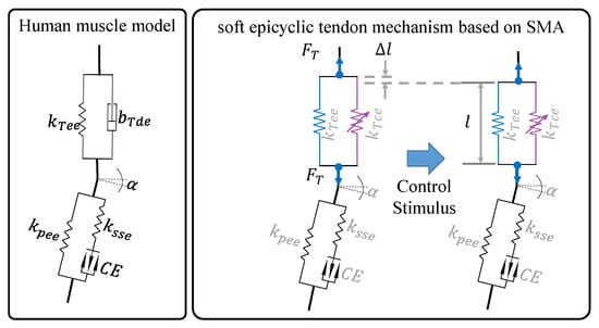
Figure 20.
Schematic representation of the soft epicyclical tendon-driven actuation system based on Shape Memory Alloy (SMA).
Consequently, the soft epicyclical tendon-driven actuation system based on SMA has been implemented, placing a wire of SMA in parallel with a Nylon wire. The used shape memory alloy wire is a FLEXINOL© actuator—which is a trade name for nickel–titanium SMA wires—with 0.38 mm diameter, bought at Dynallow Inc. [34]. Figure 21 shows the implementation in the new robotic finger.
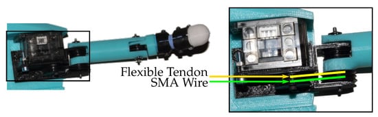
Figure 21.
Physical implementation of the soft epicyclical tendon-driven actuation system based on SMA.
Preliminary tests have shown that the substitution of the damper element by an SMA wire can reduce or eliminate the overshoot of dependent joint angles. Analytically, it can be seen that a variable stiffness element, in parallel with an elastic element, can handle global stiffness of the mechanism and render it adaptable to several grasping situations. On the other hand, the transient state of the system can be changed from a critically-damped to an over-damped behavior. In the following, our research aims to test and validate this theory, through the implementation of a test platform, following the same architecture described in this paper. We expect that the variable stiffness can fulfill damping requirements, helping to mimic the behavior of human muscles.
The retained identification of the SMA Young’s Modulus during full austenite and martensite phases was proposed by Ramirez Arias [22], who performed an experiment using a test machine. Seven specimens of SMA wires were tested in uniaxial tension: (1) The wires are tested with thermal stimulus to measure the Young’s modulus in full austenite phase; (2) then, a thermal stimuli is removed to measure the Young’s modulus in full martensite phase.
Ramirez Arias [22] generated the thermal stimuli using a DC source, in which voltage and current are controlled, then the temperature was measured and when it exceeded the reported max temperature of C [34], the measure of the Young’s Modulus in full austenite phase was performed. The identified Young’s modulus in martensite and austenite phases is presented in Table 2.
Table 2.
Measured Young’s modulus in martensite and austenite phases.
As a result, we obtain a soft epicyclical mechanism based on SMA, which can control the stiffness of joints. This mechanism can help to mimic human muscles behavior accurately. Moreover, the possibility of variable stiffness in joints led to the increment in the performance of steady grasping.
5. Conclusions
Following the human grasping requirements, a new actuation system—so-called the soft epicyclical tendon-based mechanism—is developed to add a soft behavior to the robotic finger joints. The mechanism actuates the robotic finger prosthesis ProMain-I, which is under-actuated. The driving mechanism is able to accurately fix the joint-angles relations during free movement.
The designed ProMain-I finger is also assessed experimentally, with the aim of validating its performance in terms of displacement and force. The PIP and DIP joint angles show an under-damped behavior for the PIP and the DIP joints when the finger gets in contact with the platform where the force sensor is placed. We compare the angle value obtained from the kinematic measure with the calculated angle value issued from fixed transmission relation of the soft epicyclical mechanism. As a result, we find that the mean absolute error of the angle is , and the standard deviations is . With respect to the angle of the DIP joint, the mean absolute error is and the standard deviations is .
Finally, we introduce the design of a new version of the soft epicyclical mechanism using an SMA wire in parallel to the flexible tendon for the ProMain-I robotic finger. This actuation system allows controlling the stiffness of the actuated joints handling the damping effect, evidenced during the experiments performed with the ProMain-I finger.
6. Patents
Chaîne articulée comprenant un unique actionneur et ensemble de chaînes articulées associées, patent number FR1656914 [31]: The invention relates to an articulated chain (1), forming, in particular, all or part of a finger, or an arm, or a leg, or a manipulator of said articulated chain (1), comprising a first member (10), a second member (20), and a flexible seam (30)—the first member (10) and the second member (20) being each attached to the flexible seam (30), which is made of a material having a Shore A hardness of between 0 and 50.
Supplementary Materials
The following is available online at https://www.mdpi.com/2076-0825/8/3/58/s1. Video S1: Experimental Assessment of the Soft Driving Epicyclical Mechanism using a Robotic Finger.
Author Contributions
Conceptualization, A.R., J.R.; data curation, P.C., A.R., and J.R.; formal analysis, A.R., J.R.; investigation, P.C., A.R., and J.R.; methodology, J.R; validation, A.R., J.R.; writing—original draft, P.C., A.R., and J.R.; writing—review and editing, P.C., A.R., and J.R.
Funding
This research was funded by Universidad Militar Nueva Granada grant number INV-DIS-2961.
Acknowledgments
We would like to acknowledge Université Paris Lumières, and particularly the team of Mécanique des matériaux, des structures et de systèmes at the LEME laboratory for their support. Authors also acknowledge the Universidad Militar Nueva Granada for their support during the research.
Conflicts of Interest
The authors declare no conflict of interest.
Abbreviations
The following abbreviations are used in this manuscript:
| SMA | Shape Memory Alloy |
| MCP | Metacarpophalangeal joint |
| PIP | Proximal Interphalangeal joint |
| DIP | Distal Interphalangeal joint |
| FDS | Flexor Digitorum Superficialis muscle |
| M | metacarpus |
| PP | Proximal phalanges |
| MP | Medial phalangesnd |
| DP | Distal phalanges |
| The contractile element | |
| The parallel elastic element of the muscle | |
| The muscle’s serial elastic element | |
| The tendon’s elastic element | |
| The tendon’s damping element | |
| The pennation angle |
References
- Zodey, S.; Pradhan, S.K. Matlab Toolbox for Kinematic Analysis and Simulation of Dexterous Robotic Grippers. Procedia Eng. 2014, 97, 1886–1895. [Google Scholar] [CrossRef]
- Belter, J.T.; Dollar, A.M. Performance characteristics of anthropomorphic prosthetic hands. In Proceedings of the IEEE International Conference on Rehabilitation Robotics, Rehab Week, Zurich, 27 June–1 July 2011; pp. 921–927. [Google Scholar]
- Narasimhan, S.; Siegel, D.; Hollerbach, J.; Biggers, K.; Gerpheide, G. Implementation of control methodologies on the computational architecture for the Utah/MIT hand. In Proceedings of the International Conference on Robotics and Automation, San Francisco, CA, USA, 7–10 April 1986; Volume 3, pp. 1884–1889. [Google Scholar]
- Jacobsen, S.C.; Iversen, E.K.; Knutti, D.F.; Johnson, R.T.; Biggers, K.B. Design of the Utah/MIT dextrous hand. In Proceedings of the IEEE International Conference on the Robotics and Automation, San Francisco, CA, USA, 7–10 April 1986; Volume 3, pp. 1520–1532. [Google Scholar]
- Jacobsen, S.C.; Wood, J.E.; Knutti, D.F.; Biggers, K.B. The UTAH/MIT dextrous hand: Work in progress. Int. J. Robot. Res. 1984, 3, 21–50. [Google Scholar] [CrossRef]
- Jacobsen, S.; McCammon, I.; Biggers, K.; Phillips, R. Tactile sensing system design issues in machine manipulation. In Proceedings of the International Conference on Robotics and Automation, Raleigh, CA, USA, 31 March–3 April 1987; Volume 4, pp. 2087–2096. [Google Scholar]
- Grebenstein, M. Approaching Human Performance. Ph.D. Thesis, Eidgenössische Technische Hochschule ETH Zürich, Zürich, Switzerland, 2012. [Google Scholar]
- Bridgwater, L.B.; Ihrke, C.A.; Diftler, V.; Abdallah, M.E.; Radford, N.A.; Rogers, J.M.; Yayathi, S.; Askew, R.S.; Linn, D.M. The Robonaut 2 hand–Designed to do work with tools. In Proceedings of the International Conference on Robotics and Automation (ICRA), St. Paul, MN, USA, 14–18 May 2012; pp. 3425–3430. [Google Scholar]
- Diftler, V.; Mehling, J.S.; Abdallah, M.E.; Radford, N.A.; Bridgwater, L.B.; Sanders, A.M.; Askew, R.S.; Linn, D.M.; Yamokoski, J.D.; Permenter, F.A.; et al. Robonaut 2—The first humanoid robot in space. In Proceedings of the International Conference on Robotics and Automation (ICRA), Shanghai, China, 9–13 May 2011; pp. 2178–2183. [Google Scholar]
- Okada, T. Object-Handling System for Manual Industry. Proc. IEEE Trans. Syst. Man Cybern. 1979, 9, 79–89. [Google Scholar] [CrossRef]
- Yamano, I.; Maeno, T. Five-fingered Robot Hand using Ultrasonic Motors and Elastic Elements. In Proceedings of the 2005 IEEE International Conference on Robotics and Automation, Barcelona, Spain, 18–22 April 2005; pp. 2673–2678. [Google Scholar]
- Melchiorri, C.; Palli, G.; Berselli, G.; Vassura, G. Development of the UB Hand IV: Overview of Design Solutions and Enabling Technologies. IEEE Robot. Autom. Mag. 2013, 20, 72–81. [Google Scholar] [CrossRef]
- Ottobock. SensorHand Speed VariPlus Speed; Ottobock: Duderstadt, Germany, 2013. [Google Scholar]
- Mnyusiwalla, H.; Vulliez, P.; Gazeau, J.P.; Zeghloul, S. A New Dexterous Hand Based on Bio-Inspired Finger Design for Inside-Hand Manipulation. IEEE Trans. Syst. Man Cybern. Syst. 2016, 46, 809–817. [Google Scholar] [CrossRef]
- Touch Bionics. i-limbTMultra Clinician Manual, 2nd ed.; Touch Bionics: Mansfield, MA, USA, 2013. [Google Scholar]
- Gosselin, C.; Pelletier, F.; Laliberte, T. An anthropomorphic underactuated robotic hand with 15 DoFs and a single actuator. In Proceedings of the IEEE International Conference on Robotics and Automation, Pasadena, CA, USA, 19–23 May 2008; pp. 749–754. [Google Scholar]
- DeLaurentis, K.J.; Mavroidis, C. Mechanical design of a shape memory alloy actuated prosthetic hand. Technol. Health Care 2002, 10, 91–106. [Google Scholar]
- Odhner, L.U.; Jentoft, L.P.; Claffee, M.R.; Corson, N.; Tenzer, Y.; Ma, R.R.; Buehler, M.; Kohout, R.; Howe, R.D.; Dollar, A.M. A compliant, underactuated hand for robust manipulation. Int. J. Robot. Res. 2014. [Google Scholar] [CrossRef]
- Ottobock. The Michelangelo® Hand in Practice—Therapy and Rehabilitation; Ottobock: Duderstadt, Germany, 2012. [Google Scholar]
- Mouri, T.; Kawasaki, H.; Yoshikawa, K.; Takai, J.; Ito, S. Anthropomorphic robot hand: Gifu hand III. In Proceedings of the International Conference ICCAS, Jeonbuk, Korea, 16–19 October 2002; pp. 1288–1293. [Google Scholar]
- Johannes, M.S.; Bigelow, J.D.; Burck, J.M.; Harshbarger, S.D.; Kozlowski, M.V.; Doren, V.T. An overview of the developmental process for the modular prosthetic limb. Johns Hopkins APL Tech. Dig. 2011, 30, 207–216. [Google Scholar]
- Ramirez Arias, J.L. Development of an Artificial Muscle for a Soft Robotic Hand Prosthesis. Ph.D. Thesis, Univertisé Parias Nanterre, Nanterre, France, 2016. [Google Scholar]
- Hill, A.V. The Series Elastic Component of Muscle. Proc. R. Soc. Lond. B Biol. Sci. 1950, 137, 273–280. [Google Scholar] [PubMed]
- Hill, A.V. The abrupt transition from rest to activity in muscle. Proc. R. Soc. Lond. B Biol. Sci. 1949, 136, 399–420. [Google Scholar] [CrossRef] [PubMed]
- Rus, D.; Tolley, M.T. Design, fabrication and control of soft robots. Nature 2015, 521, 467–475. [Google Scholar] [CrossRef] [PubMed]
- Bartlett, N.W.; Tolley, M.T.; Overvelde, J.T.B.; Weaver, J.C.; Mosadegh, B.; Bertoldi, K.; Whitesides, G.M.; Wood, R.J. A 3D-printed, functionally graded soft robot powered by combustion. Science 2015, 349, 161–165. [Google Scholar] [CrossRef] [PubMed]
- Tawk, C.; in het Panhuis, M.; Spinks, G.M.; Alici, G. Bioinspired 3D Printable Soft Vacuum Actuators for Locomotion Robots, Grippers and Artificial Muscles. Soft Robot. 2018, 5, 685–694. [Google Scholar] [CrossRef] [PubMed]
- Ramírez, J.L.; Rubiano, A.; Jouandeau, N.; El korso, M.N.; Gallimard, L.; Polit, O. Hybrid kinematic model applied to the under-actuated robotic hand prosthesis ProMain-I and experimental evaluation. In Proceedings of the 14th IEEE International Conference on Rehabilitation Robotics (ICORR), Singapore, 11–14 August 2015. [Google Scholar]
- Ramírez, J.L.; Rubiano, A.; Jouandeau, N.; Gallimard, L.; Polit, O. New Morphological Optimization of Prosthesis’ Finger for Precision Grasping. In New Trends in Medical and Service Robots: Human Centered Analysis, Control and Design; Wenger, P., Chevallereau, C., Pisla, D., Bleuler, H., Rodić, A., Eds.; Springer: Berlin/Heidelberg, Germany, 2016; pp. 249–263. [Google Scholar]
- Ramírez, J.L.; Rubiano, A.; Jouandeau, N.; Gallimard, L.; Polit, O. Artificial Muscles Design Methodology Applied to Robotic Fingers. In Smart Structures and Materials; Araujo, A., Mota Soares, C.A., Eds.; Springer: Berlin/Heidelberg, Germany, 2016; pp. 209–225. [Google Scholar]
- Rubiano, A.; Ramírez, J.L.; Gallimard, L.; Polit, O.; Jouandeau, N. Chaîne Articulée Comprenant un Unique Actionneur et Ensemble de Chaînes Articulées Associées. FR Patent FR 3,054,157 A1, 26 January 2018. [Google Scholar]
- Nurzaman, S.; Iida, F.; Laschi, C.; Ishiguro, A.; Wood, R. Soft Robotics [TC Spotlight]. IEEE Robot. Autom. Mag. 2013, 20, 24–95. [Google Scholar]
- Tarsha-Kurdi, F.; Landes, T.; Grussenmeyer, P. Hough-transform and extended RANSAC algorithms for automatic detection of 3D building roof planes from lidar data. In Proceedings of the ISPRS Workshop on Laser Scanning, Espoo, Finland, 12–14 September 2007; Volume 36, pp. 407–412. [Google Scholar]
- Dynalloy Inc. Technical Characteristics of FLEXINOL Actuator Wires, F1140Rev I.2 ed.; Dynalloy Inc.: Irvine, CA, USA, 2015. [Google Scholar]


© 2019 by the authors. Licensee MDPI, Basel, Switzerland. This article is an open access article distributed under the terms and conditions of the Creative Commons Attribution (CC BY) license (http://creativecommons.org/licenses/by/4.0/).