Article

Semi-Active Vibration Control of a Non-Collocated Civil Structure Using Evolutionary-Based BELBIC

by
Manuel Braz César
1,2,*,
João Paulo Coelho
1,3 and
José Gonçalves
1,3
1
Instituto Politécnico de Bragança, Escola Superior de Tecnologia e Gestão, 5300-253 Bragança, Portugal
2
Institute of R&D in Structures and Construction (CONSTRUCT), Laboratory for Earthquake and Structural Engineering (LESE), 4200-465 Porto, Portugal
3
CeDRI—Centro de Investigação em Digitalização e Robótica Inteligente, 5300-253 Bragança, Portugal
*
Author to whom correspondence should be addressed.
Actuators 2019, 8(2), 43; https://doi.org/10.3390/act8020043
Submission received: 15 April 2019 / Revised: 10 May 2019 / Accepted: 12 May 2019 / Published: 15 May 2019

Abstract

:
A buildings resilience to seismic activity can be increased by providing ways for the structure to dynamically counteract the effect of the Earth’s crust movements. This ability is fundamental in certain regions of the globe, where earthquakes are more frequent, and can be achieved using different strategies. State-of-the-art anti-seismic buildings have, embedded on their structure, mostly passive actuators such as base isolation, Tuned Mass Dampers (TMD) and viscous dampers that can be used to reduce the effect of seismic or even wind induced vibrations. The main disadvantage of this type of building vibration reduction strategies concerns their inability to adapt their properties in accordance to both the excitation signal or structural behaviour. This adaption capability can be promoted by adding to the building active type actuators operating under a closed-loop. However, these systems are substantially larger than passive type solutions and require a considerable amount of energy that may not be available during a severe earthquake due to power grid failure. An intermediate solution between these two extremes is the introduction of semi-active actuators such as magneto–rheological dampers. The inclusion of magneto–rheological actuators is among one of the most promising semi-active techniques. However, the overall performance of this strategy depends on several aspects such as the actuators number and location within the structure and the vibration sensors network. It can be the case where the installation leads to a non-collocated system which presents additional challenges to control. This paper proposes to tackle the problem of controlling the vibration of a non-collocated three-storey building by means of a brain–emotional controller tuned using an evolutionary algorithm. This controller will be used to adjust the stiffness coefficient of a magneto–rheological actuator such that the building’s frame oscillation under earthquake excitation, is mitigated. The obtained results suggest that, using this control strategy, it is possible to reduce the building vibration to secure levels.

1. Introduction

Earthquakes are a natural phenomena that has one of the most the severe impact on the structural integrity of buildings. History is full of examples where the energy of seismic waves devastated entire cities. In general, the civil buildings can be made more robust under those types of Earth’s crust movement by proper engineering design and by including additional technological layers over the standard structural frame. Modern anti-seismic buildings include mostly passive actuators such as base isolation, TMDs and viscous dampers that can be used to weaken the effect of building vibrations due to external causes such as earthquakes. The main drawback of this strategy is related with its inability to change the building dynamics according to the disturbance energy. This limitation can be circumvented by the introduction of active control systems. However, these system are bulkier and require a considerable amount of energy that may not be available during a severe earthquake. Semi-active vibration reduction strategies can allow us to bypass some of these disadvantages while maintaining the ability to modify the dynamic response of buildings to the disturbances. The difference between active and semi-active vibration mitigation system depends essentially on the type of actuator in use. Pneumatic and hydraulic cylinders are examples of active actuators whereas magneto–rheological dampers or piezoelectric devices are classified as semi-active actuators. Besides requiring less external energy, in general semi-active vibration control leads to increased overall stability compared to active control [1,2]. For those reasons, the use of semi-active control systems is a trending research theme and can be found applied in many distinct engineering areas such as vehicles suspensions and smart structures just to name a few [3,4,5,6,7,8,9,10,11,12,13,14].
Smart anti-seismic civil structures rely heavily on the information provided by sensors and have the ability to change their dynamics by means of actuators whose behaviour is regulated by control algorithms. The control algorithm acts as the process brain and decides what type of actuation to perform in the presence of disturbances. Those disturbances can be directly measured by means of sensors such as accelerometers and strain gauges scattered along the building [15].
There are a large range of possible control algorithms that can be used in this context: from classical Proportional, Integral and Derivative (PID) controllers up to more elaborated computational intelligence-based methods. Artificial intelligence methods are gradually taking their place in the current structural control systems panorama and proofing themselves as an effective method by leaving the realm of research and crystallizes into real civil structures application. Indeed, the NTT Facilities Inc. building, located in Tokyo, Japan has, since 2017, a seismic control system-based on artificial intelligence paradigms. The system, designed to control long-period ground motion, analyzes the building motion using artificial intelligence algorithms and counteracts the oscillation imposed by earthquakes by artificially generating vibrations with actuators. The authors strongly believe that the future trend in civil structures robustness will include the integration of artificial intelligence into buildings.
There are myriads of distinct soft-computing and artificial intelligence methods that can be applied in the problem of buildings vibration reduction. Brain–emotional learning-based intelligent control (BELBIC) is one of such paradigms. It has already been considered within the context of building vibration mitigation. For example, Reference [16] presents a numerical study where BELBIC was used to reduce the vibration of a building equipped with a magneto–rheological damper.
The two main problems with the use of BELBIC as a control strategy is, on the one hand, its very large number of parameters and, on the other, the overall controller sensitivity to the value of those parameters. In [17] this issue was tackled by means of an off-line training procedure where the BELBIC controller parameters were obtained by an evolutionary search algorithm. The article has shown that the vibration of one degree-of-freedom building under an 1D base disturbance was largely improved by this method when compared to simple ad-hoc controller tuning.
The present work follows from the above-mentioned one by extending it to a non-collocated control problem where a three-storey building and one actuator are considered. When compared to collocated systems, the control design of non-collocated processes is more challenging due to the increased stability degradation exhibited by those types of approaches. This work will show that the BELBIC controllers can be used for vibration reduction for non-collocated civil structure systems where its parameters can be obtained numerically by using a particle swarm optimization (PSO) algorithm.
This paper will be divided into four main sections where, after this first introduction, the building vibration problem is described and the Brain Emotional Learning (BEL) control methodology is introduced. Section 2.2 will disclose the questions regarding the dynamic description of both the magneto–rheological dampers and the three-storey building. Section 2.3 and Section 2.4 describe, in abstract, the main concepts of BELBIC control strategy and its overall architecture. Section 2.5 presents a briefly, the general idea behind the particle swarm optimization algorithm. This latter method will be used to define the parameters of a BELBIC controller such as to mitigate the vibration on a three-storey building due to ground motion caused by an earthquake signal. Several simulations were carried out whose details and obtained results are presented at Section 3. This paper resumes with Section 4, where the conclusions, remarks and the direction of future works are presented.

2. Problem Statement

Structural vibration control aim to produce buildings that are able to withstand severe dynamic loads such as the ones created by seismic waves. This goal can be accomplished through proper building design and by the addition of passive, active or semi-active elements to the structure. Currently, great attention is given to semi-active elements due to the range of advantages they exhibit when compared to the remain solutions. Power consumption and overall system stability are just two of them.
Within the universe of semi-active actuators, magneto–rheological dampers are those who present themselves as more promising solutions. Those types of elements can change their damping coefficient by means of an external magnetic field which, in turn, is controlled by an applied electrical current. However, due to high non-linearity behaviour such as hysteresis, their use within a feedback control framework adds additional challenges. For example, common PID controllers are unable to provide a suitable control signal for the broad range of different operating points exhibited by the overall system. For this reason, computational intelligence-based controllers are more suited to adapt to all those different regimes.
Within the universe of different possible computational intelligence-based controllers, the current work considers the brain–emotional leaning (BEL) controller. The adaption mechanism behind these types of controller is inspired by the sections of the brain responsible to yield emotional reactions. Pair of stimuli and reactions are learned by the BEL model which includes a mathematical representation of the brain’s amygdala, orbitofrontal cortex and thalamus.
The behaviour and performance of a BELBIC-based control system strongly depend on its parametrization. Due to the large number of existing degrees-of-freedom, ad-hoc approaches to controller tuning only lead to sub-optimal closed loop responses. For this reason, automated parameter tuning methods must be considered. In this work, the controller design will be performed off-line, by means of a particle swarm optimization search method. This scheme requires a mathematical model of both the building and the actuator. In the following sections a three-storey building model with one installed magneto–rheological (MR) actuator will be described. Additionally, a short overview on BELBIC and PSO will be provided. Finally, the overall control system architecture will be presented.

2.1. The Building Mathematical Model

In this case study, the MR damper is located between ground and first floor as shown in the left hand-side of Figure 1. The mechanical behaviour of the building can be described by the lumped element model illustrated in the right-hand side of Figure 1.
The equation of motion describing the response of the system is defined as:
M d 2 X ( t ) d t 2 + C d X ( t ) d t + K · X ( t ) = Γ · f c 1 ( t ) M · λ d 2 x g ( t ) d t 2 ,
where X ( t ) defines the displacement response, f c 1 ( t ) the control force, and d 2 x g ( t ) d t 2 the ground acceleration. The vectors Γ = 1 0 0 T and λ = 1 1 1 T regard the location of both the control force and the earthquake excitation, respectively. In addition, M, C and K are the 3 × 3 mass, damping and stiffness matrices described by:
M = m 1 0 0 0 m 2 0 0 0 m 3 ,
C = c 1 + c 2 c 2 0 c 2 c 2 + c 3 c 3 0 c 3 c 3 ,
K = k 1 + k 2 k 2 0 k 2 k 2 + k 3 k 3 0 k 3 k 3 .
For the current work, the above matrices coefficients were defined as: m 1 = m 2 = m 3 = 100 kg; c 1 = 175 Ns/m, c 2 = c 3 = 50 Ns/m and k 1 = k 2 = k 3 = 6 × 10 5 N/m.
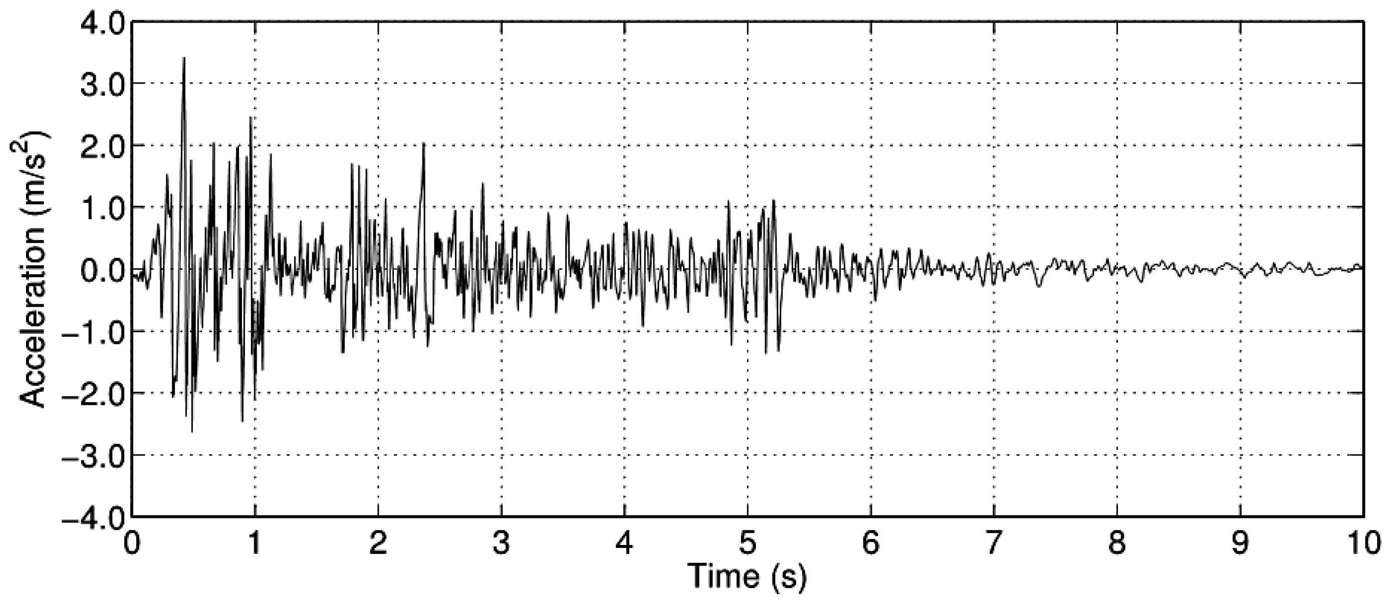
Moreover, the ground motion pattern imposed to the system during the simulations was derived from the 1940 north-south component of the El-Centro earthquake. Figure 2 presents the acceleration values along a time window of ten seconds taken at a sampling period of 200 ms.

2.2. Magneto-Rheological Damper Model

A MR damper is a device where a plunger moves inside a chamber filled with magneto–rheological fluid. This fluid is composed of microscopic magnetizable particles in suspension over a non-magnetic carrier fluid. The MR fluid possesses the ability to change its rheological properties when subjected to the action of an external magnetic field. This action is reversible in the sense that, when the magnetic field ceases, the yield stress is reduced [18]. The magnetic field is generated through electromagnets added to the damper body and its intensity is a function of the electrical current applied to the electromagnets coil wires. The MR damping behaviour can then be modified by proper selection of the electrical current delivered to the electromagnets. It is worth noticing that MR dampers can only produce stiffness by the modulation of the MR nonlinear damping force over each half cycle [19,20,21,22].
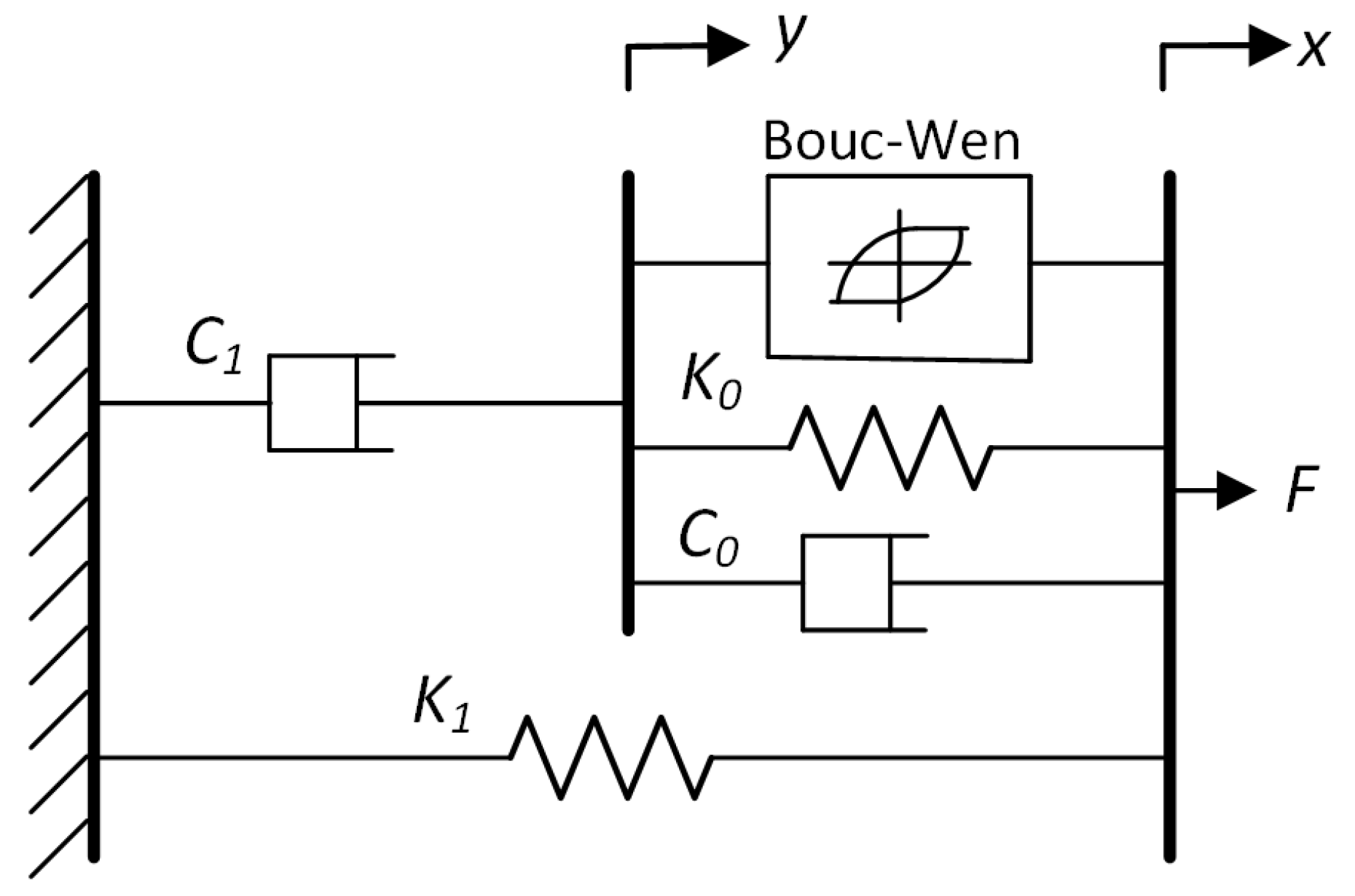
In order to be able to design the controller, a mathematical model of this device must be considered. The dynamic behaviour of an MR damper must take into consideration several phenomena [23,24]. One of such phenomena is hysteresis due to non-linear friction mechanisms [25,26,27,28]. Additional information on MR actuators dynamics to can be found at [29,30]. To model the hysteresis dynamics, a Bouc–Wen model was used leading to the overall MR damper lumped parameter model represented in Figure 3.
In this model, the force is given by the first order differential equation:
F ( t ) = c 1 d y ( t ) d t + k 1 x ( t ) x 0 ,
where,
d y ( t ) d t = 1 c 0 + c 1 α z ( t ) + c 0 d x ( t ) d t + k 0 x ( t ) y ( t ) ,
and,
d z ( t ) d t = β d x ( t ) d t z ( t ) z ( t ) n 1 γ d x ( t ) d t z ( t ) n + A d x ( t ) d t .
The controller is used to change the damping force of the MR damper by changing the magnetic field applied to the MR fluid using and electromagnet in the piston head. This produces an apparent modification in the fluid viscosity that modifies the hysteretic response of the actuator under cyclic loading. The effect can be described by a pre-yield and post-yield behaviour that is current-dependent and can be controlled to increase or decrease the amount of energy that has been dissipated during each cycle (dissipative damping force). Although a stiffness effect is present in the actuator response (usually a small static value), the main purpose and contribution is to change the damping state. Also, as mentioned, k 0 describes the pre-yield stiffness of the MR damper that is also not controllable [31].
Notice that some of the model parameters are independent of the electrical current I. In particular, and during this work simulations, the coefficient A will be equal 10.013 , β equal to 3.044 mm 1 , γ is assumed to be equal to 0.103 mm 1 . The remain coefficient values are defined as k 0 = 1.121 N/mm, f 0 = 40 N, and n = 2 .
The parameters that are dependent on the electrical current value are described by the following polynomial equations:
α ( I ) = 826.67 · I 3 + 905.14 · I 2 + 412.53 · I + 38.24 ,
c 0 ( I ) = 11.73 · I 3 + 10.51 · I 2 + 11.02 · I + 0.59 ,
c 1 ( I ) = 54.4 · I 3 + 57.03 · I 2 + 64.57 · I 4.73 .
It is important to highlight that, before being applied to the MR actuator, the electrical current passes over a first-order low-pass filter with the transfer function which describes the coil current dynamics:
H ( s ) = 130 s + 130 .
It is worth to notice that the inter-storey drifts are the signals fed to the BEL controller which, in turn, is responsible to compute the control signal to be delivered to the MR actuator power driver. As a result of the central action played by this controller, the following section is dedicated to describing the main features and operating principles of a BEL controller.

2.3. The BEL-Based Control System

Emotions are considered to be an invaluable resource in species survival and adaptation which were incorporated by the evolutionary process as a way to shorten the reaction time. Hence, instead of using the more time-consuming brain processing path, the action by emotion would be a faster way. Since emotional behaviour is a key aspect in species robustness and adaptability, it would be central to translate this feature into machines. It was in this framework that [32], inspired by the limbic mathematical model developed by [33], devises a new control systems paradigm designated by brain–emotional learning-based intelligent control (BELBIC). Since then, this control strategy has been applied in a myriad of distinct engineering problems. For example in [16,17] a BEL controller performance was applied to semi-active vibration control and [34] have used BELBIC to control the voltage tracking in a boost converter. In [35] a sliding mode control-based on BELBIC was tested over robotic manipulators. The work of [36] describes the use of a BELBIC-based control system to track the position of an hydraulic system. On the other hand, Reference [37] a BELBIC controller was applied to an interline power-flow device. Aside from the above mentioned references, the brain–emotional paradigm has been applied in such diverse knowledge areas such as chemistry, mechanics, aerial systems, speech processing, among others [38,39,40,41,42,43,44].
The data path of a brain–emotional learning model is presented in Figure 4 where four main blocks can be identified: the thalamus, sensory cortex, orbitofrontal cortex and the amygdala. Sensory inputs are processed into the thalamus, initiating the process of stimulus response. These signals are then transferred to the sensory cortex that divides them between the amygdala and the orbitofrontal cortex. The learning process is essentially performed in the orbitofrontal cortex by a reinforcement strategy-based on punishments and rewards. A throughout description of this model is outside the scope of the current paper and the reader can refer to [33] for a more detailed description.
It was this simplified model of the limbic system that was adapted to be used within a control loop. In the original vision of BELBIC, the control signal used in the actuation process was the one computed by the above illustrated limbic model. In this framework, the stimuli and reward signals are obtained directly or indirectly from the system states. Further details regarding the use of BELBIC in the three-storey vibration control problem will be presented in the next section.

2.4. Control System Architecture

The BELBIC overall performance depends on several factors such as the way both the stimuli and reward signals are defined [45,46].
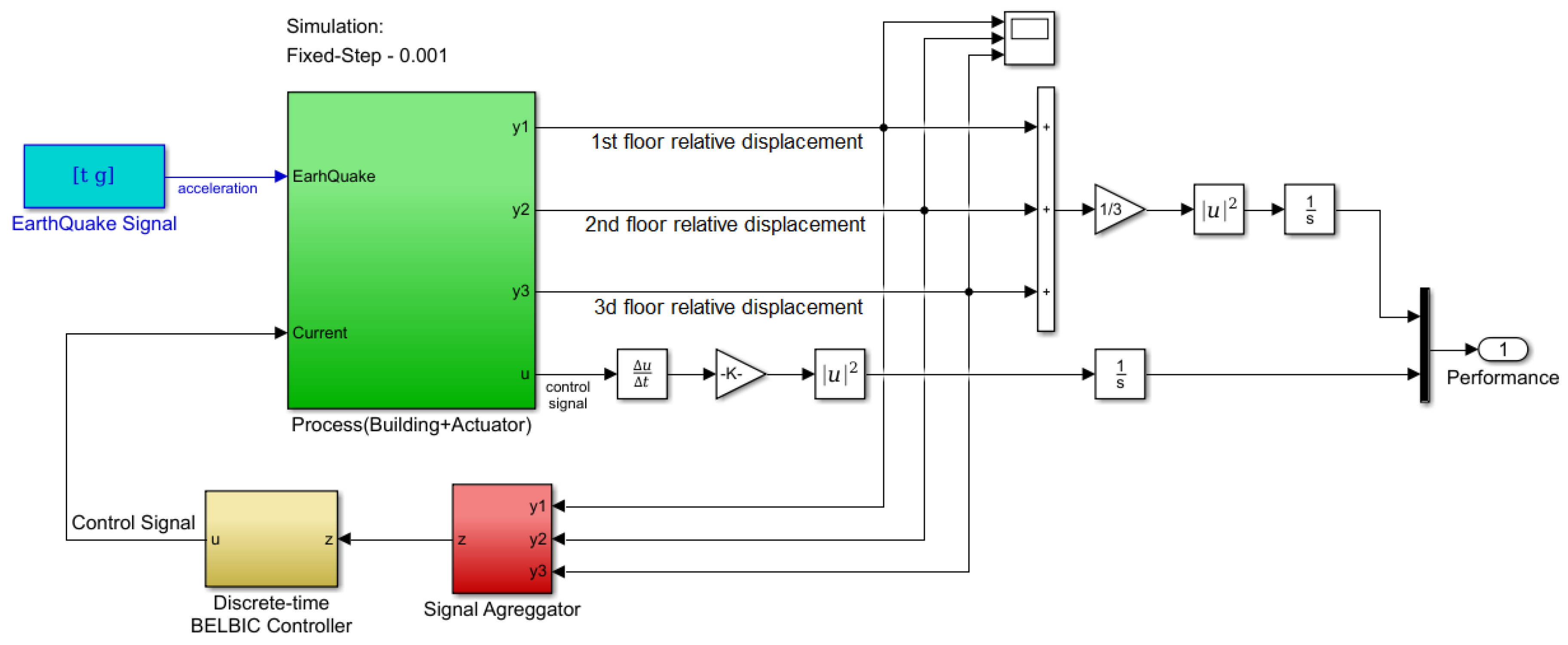
In this paper, the stimulus signal was generated from the vibration recorded in the building structure, and the reward signal uses both the vibration signals and the actual value of the control signal. The overall control methodology is illustrated Figure 5.
Let us assume that, at current time instant t, the displacement of floor i { 1 , 2 , 3 } , relative to its rest position, is d i ( t ) . The relative position drift between floor i and the one immediately below will be denoted by y i ( t ) which is equal to d i d i 1 for d 0 = 0 . In this framework, the displacement vector y is defined as y ( t ) = y 1 ( t ) y 2 ( t ) y 3 ( t ) T and the stimuli signal s ( t ) is obtained from the following linear combination:
s ( t ) = y T ( t ) · w + w u · u ( t ) ,
where u ( t ) denotes the current controller output, w u a coefficient that represents its importance in the overall stimulus signal, w = w 1 w 2 w 3 T is a vector with w i as a weight factor that defines the relative importance given to the drift y i ( t ) .
On the other hand, the emotional signal e ( t ) is computed according to:
e ( t ) = y T ( t ) · v + v u t u ( τ ) d τ ,
where v = v 1 v 2 v 3 T has the same meaning as w in the previous expression and the coefficient v u denotes the contribution of the integral of u ( t ) in global magnitude of the emotional signal.
There are some questions raised when considering a BELBIC architecture for a given control system problem. First, the definition of both the emotional and sensory signals such that they are able to represent the system’s state and the control’s objective. In the current problem, those stimuli signals are characterized through Equations (12) and (13). Secondly, one must be aware that the controller performance strongly depends on several parameters such as the amygdala and orbitofrontal learning rates. Their adjustment can be made by following several methods such as ad-hoc parameters selection, Lyapunov theory or fuzzy logic [47,48]. Evolutionary algorithms are also a common practice, such as the particle swarm optimization (PSO) which will be the adopted method in this work.

2.5. The PSO Optimization Algorithm

Since the seventies of the twentieth century, evolutionary-based search methods have been used to address function optimization for a large number of different engineering problems. There is a large number of different optimization algorithms biologically inspired. One of such methods is the PSO algorithm which is based on the collective behaviour of flocks and herds [49]. This method starts from a set of initial solutions, called particles, and moves them along the search space using a set of rules that mimics the social behaviour found in the synchronized movement of some animal species [50,51]. In particular, at a given evolutionary time t, the position and momentum of each particle i in the swarm is updated according to:
v i t + 1 = v i t + φ 1 · c i t + φ 2 · s i t ,
x i t + 1 = x i t + v i t + 1 ,
where, for a problem of dimension d, the v i = [ v i 1 , , v i d ] represent the particle i velocity and x i = [ x i 1 , , x i d ] regards the actual position of particle i.
From Equation (14a), it is possible to see that the particle’s momentum depends on the value of φ 1 [ 0 , 2 ] and φ 2 [ 0 , 2 ] whose relative values can promote the cognition-only component over the social-only and vice-verse [52]. The cognition-only component, represented by the vector c i = [ c i 1 , , c i d ] , describes the amount of the particle motion that is owed to the particle’s experience. The social-only component, expressed by s i = [ s i 1 , , s i d ] , depends on the knowledge of the remain particles in the swarm. Each of those two factors are computed according to:
c i t = p i t x i t ,
s i t = g t x i t ,
where p i = [ p i 1 , , p i d ] is the vector of the best achieved position of particle i and g ( t ) = [ g i 1 , , g i d ] represent the best position, at iteration t, within the global set of particles [53].
The simulation results presented in Section 3 were obtained using the function particleswarm(), from the Matlab ® global optimization toolbox. From the MathWorks ® documentation, this function follows the formulation introduced in [49] and extends it by following the proposals of [54,55].
The application of PSO in the context of BEL-based controller design is not a novelty and has already been considered in several articles [39,56,57,58,59]. The main difference on this work, regarding the above references, concerns the formulation of the objective function. In the present article, the cost function used was:
J = 1 n f l o o r s i = 1 n f l o o r s t s i m a i ( t ) a i 1 ( t ) 2 d t + k · t s i m d u ( t ) d t 2 d t ,
where a i ( t ) refers to the building acceleration measured at the i-th-storey, a 0 ( t ) is the ground acceleration a g ( t ) and u ( t ) the control signal. In the above expression, t s i m is the simulation time and n f l o o r s the total number of building floors and k a constant that can be used to increase or decrease the influence of the control signal variability in the overall cost function. In the simulations performed, this value was set to 0.001.
During the simulations, the PSO algorithm was parametrized assuming φ 1 equal to φ 2 and equal to 0.745. The inertia weight starts with a value of 0.1 and increases linearly up to 1.1 with the epochs counter. The addressed problem dimension is 13 and a swarm size of 100 particles was found to be suitable to consistently solve the optimization problem. Further details on the optimization parameters used are presented in the following section.

3. Simulation Results

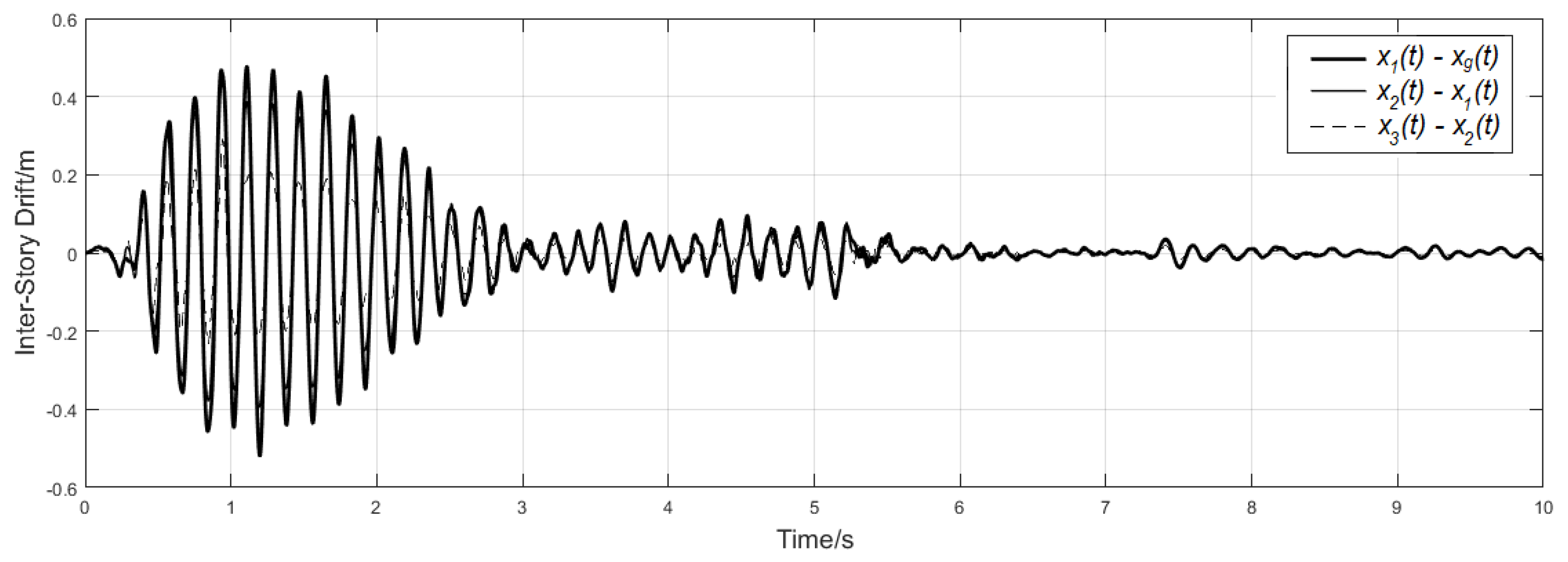
In order to evaluate the performance of the technique addressed in this article, we first observed the building dynamic response to the earthquake signal represented in Figure 2 if no MR actuator is present. When the building was excited with this signal, the simulated inter-storey drift felt at each floor is represented in Figure 6. The drift magnitude was larger in the first floor and can reach a relative peak-to-peak amplitude of more than 5 mm.
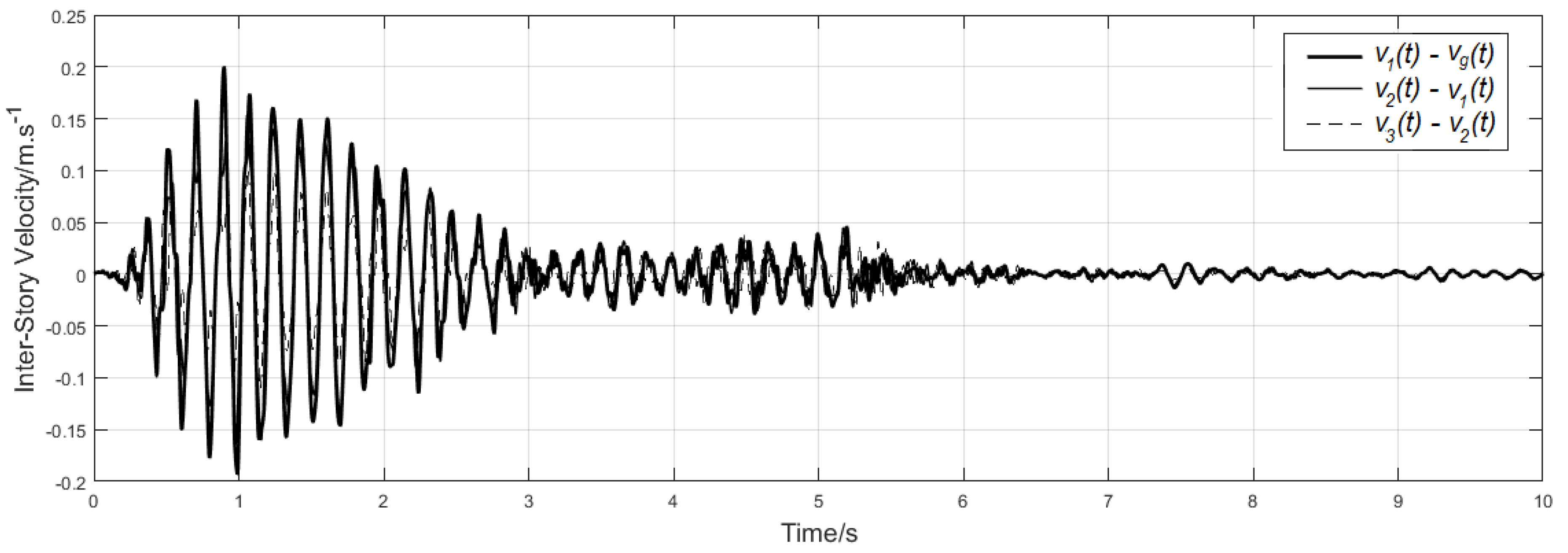
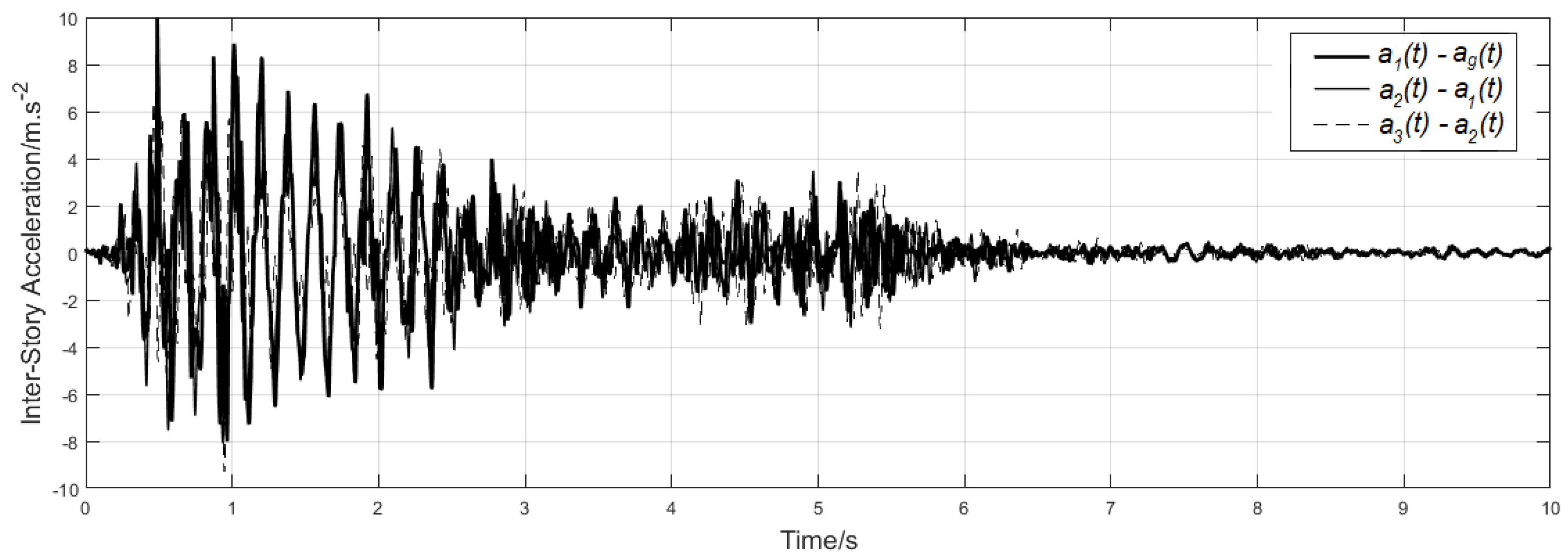
Additionally, each floor simulated relative velocity and acceleration are plotted at Figure 7 and Figure 8.
The root mean square values (RMS) of each floor registered signal, during the 10 s simulation time, are presented at Table 1. From the obtained data, it was possible to see that the peak speed and acceleration values of 0.2 ms 1 and 9.99 ms 2 were attained both at the first floor.
In order to mitigate the structural disturbance effect caused by the ground motion, a magneto–rheological actuator is considered embedded in the building as described during Section 2.1. In the current problem, the system can be viewed as non-collocated since the actuator is not affecting directly all the building stories. The role of the added actuator is to change the building dynamic response by increasing its energy dissipation capability. The actuator’s dissipating energy behaviour can be changed by modifying its damping factor through the application of an external electrical current. The amount of electrical current that must be injected depends on the current building state and on the controller algorithm. Assuming that all the building states can be measured (or indirectly observed), the controller must decide, based on those states, the suitable current to be applied to the actuator. The current work deals with the use of a multiple input-single output BELBIC controller to derive the amount of current to feed to the actuator. Those multiple inputs are algebraically manipulated in order to generate the required cues for the artificial limbic system. Section 2.4 describes the mapping performed to produce the relevant BELBIC excitation signals.
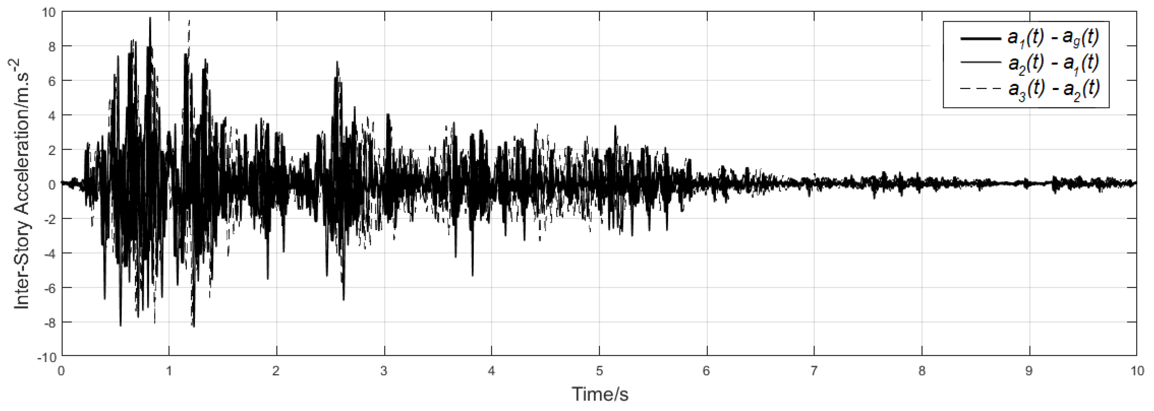
It is important to notice that the use of the BELBIC control paradigm applied to three-storey building vibration, has been already addressed by [60]. In the referred article, the BEL parameters were empirically tuned and the simulation results, to the same earthquake signal, are presented in Figure 9, Figure 10 and Figure 11. Those figures present the floor displacement, velocity and acceleration respectively assuming a BELBIC controller parameterized according to the values presented in Table 2.
Following the same procedure as for the open-loop simulation, the RMS value for each of those signals was computed and the values are presented in Table 3. Regarding the attained peak values, now the building displacement was below 3.5 mm with a maximum inter-storey velocity of 0.162 ms 1 and acceleration of 9.98 ms 2 .
Comparing the values of Table 1 with the ones of Table 3 it is possible to see that the displacement average RMS value was 48.5% lower than the one observed while operating without the MR actuator. Moreover, the structure’s RMS average velocity and acceleration was reduced in 30% and 3.1% respectively. The displacement average peak value was 31% lower in this second simulation and the velocity and acceleration maximum values also exhibited a reduction of 9.7% and 0.5%.
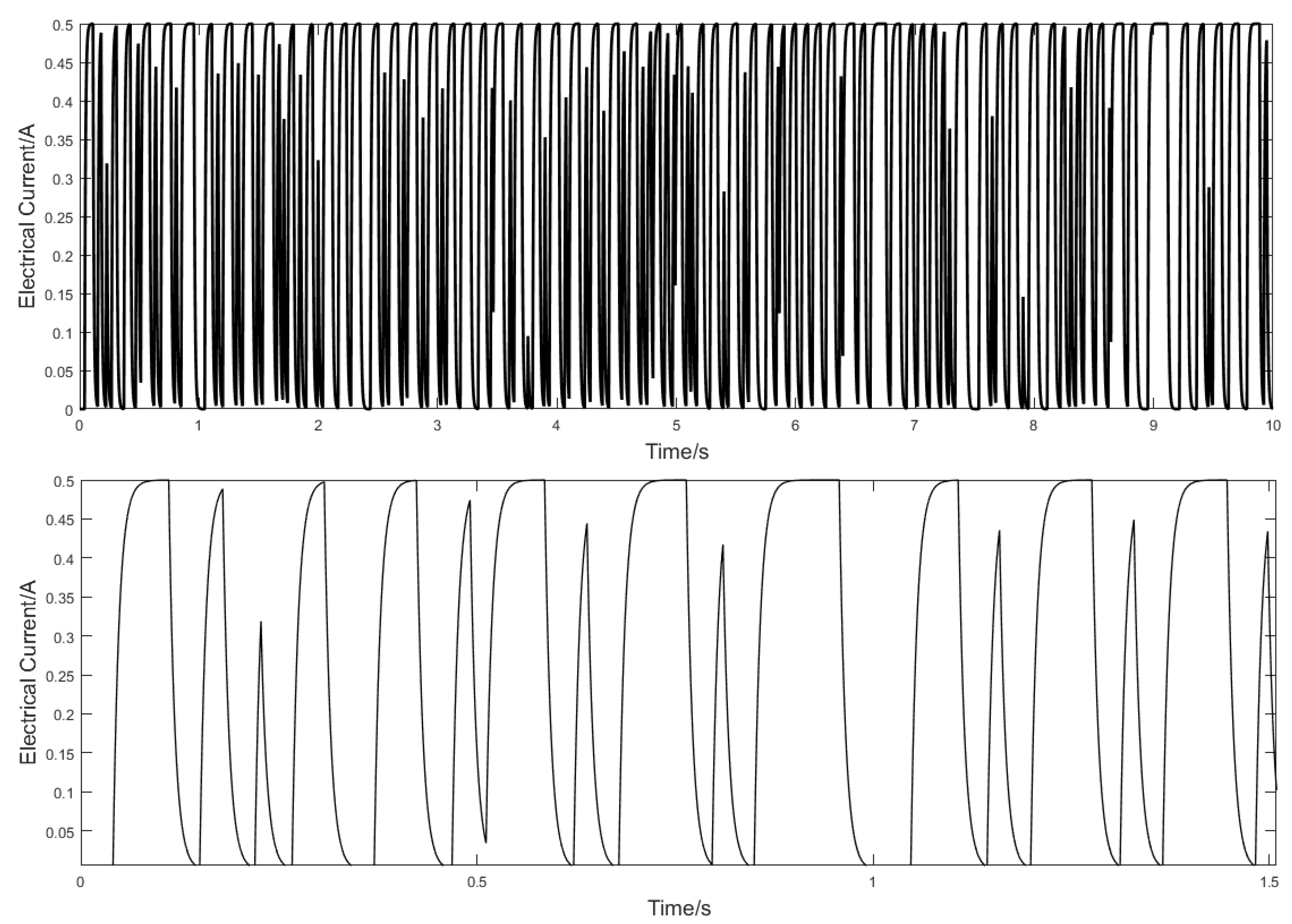
Despite the improvements observed when operating in closed-loop using a BELBIC controller, there were some improvements that could be made. One of them regarded the control signal used to drive the actuator and the other the further reduction in both the RMS and peak values obtained after a more systematic parameter tuning method.
Regarding the former, a plot of the controller generated signal is presented at Figure 12.
As can be seen, the control signal exhibited an appreciable high frequency content. High frequency control signals, within the actuator bandwidth, should be prevented since they will promote wear and tear and can lead to premature failure. Further reduction of both the building vibration and control signal switching behaviour can be accomplished by proper selection of the BELBIC controller parameters. Due to the large problem dimensionality, it is unlikely for a simple trial and error procedure to achieve proper values for 13 parameters simultaneously. Hence, a more systematic procedure resorting to an optimization scheme must be used instead. In this frame of reference, the PSO algorithm described in Section 2.5 was used where the 13 controller parameters were encoded by the PSO particles and they evolved, during the optimization method, such that the value of the objective Equation (16) decreased.
A total of 100 particles were used in this procedure and an average value of 500 epochs have been executed for each tryout. Several tryouts have been executed where, in average, more than 85% of them consistently converged to the same solution. The solution obtained from this approach is presented, approximated to two significant digits, in the last row of Table 4. In the same table, the first two rows define the search limits considered for each variable: the first row represents the lower bound and the second the upper bound values.
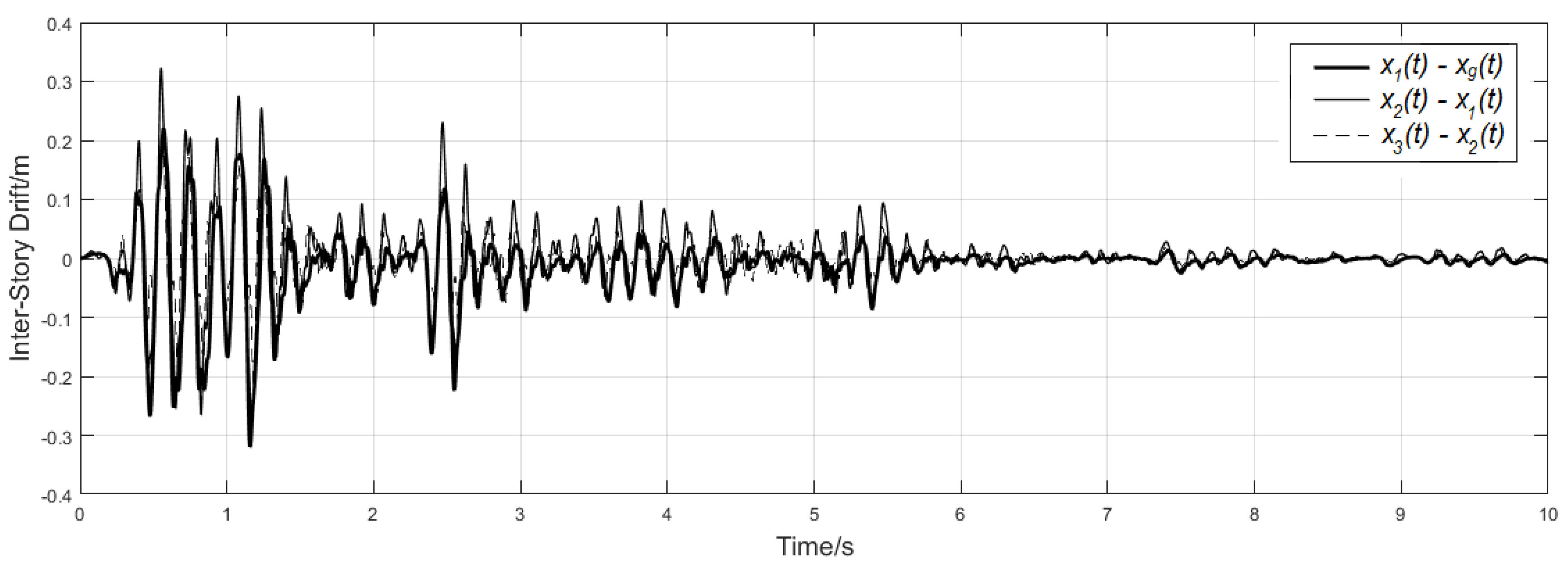
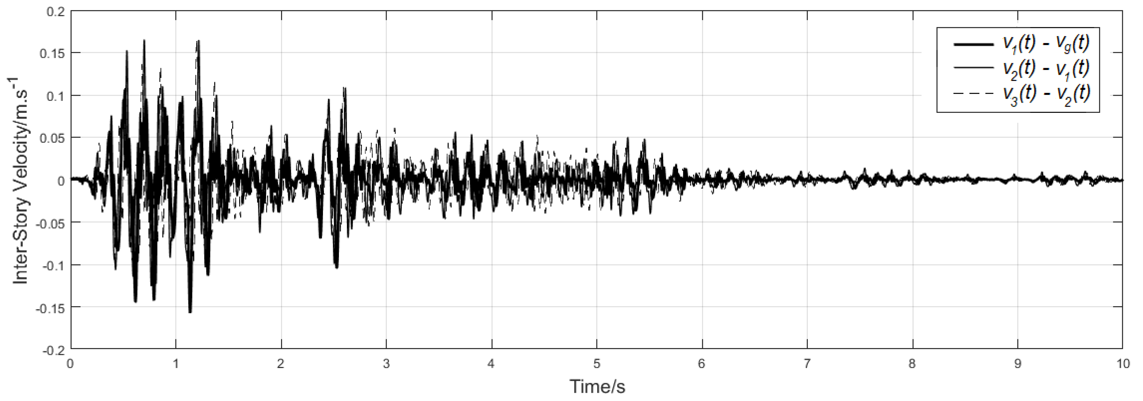
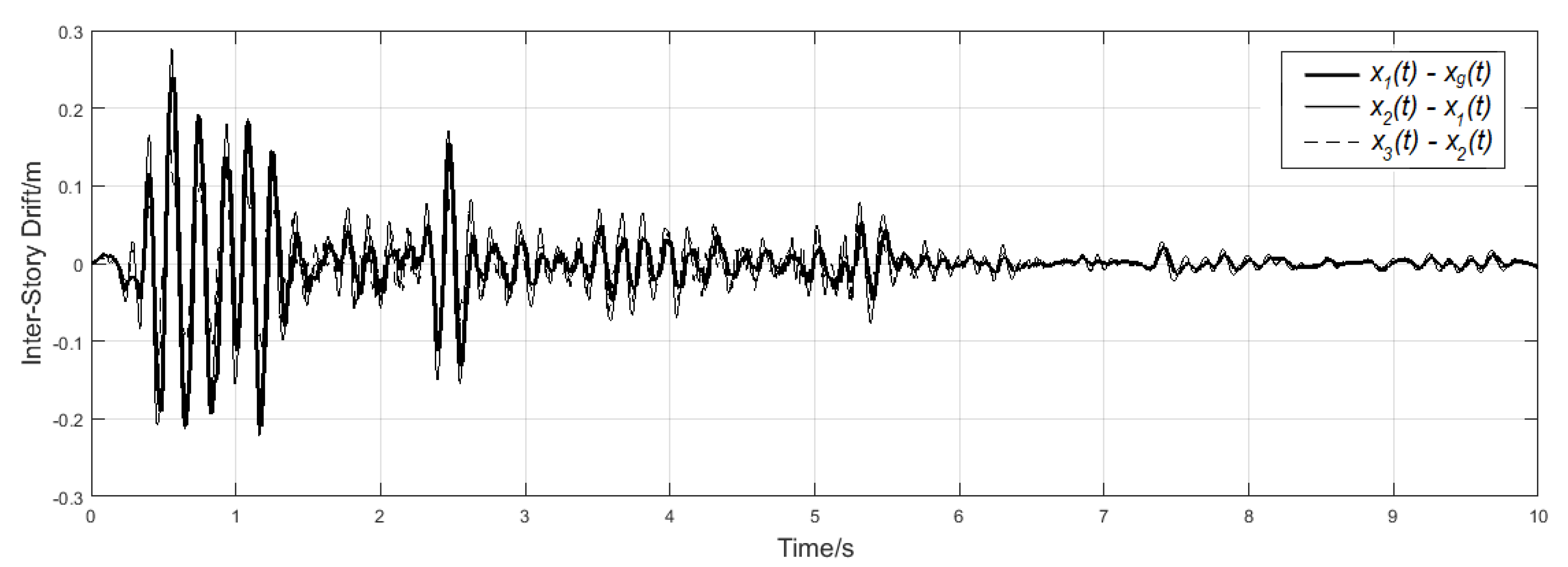
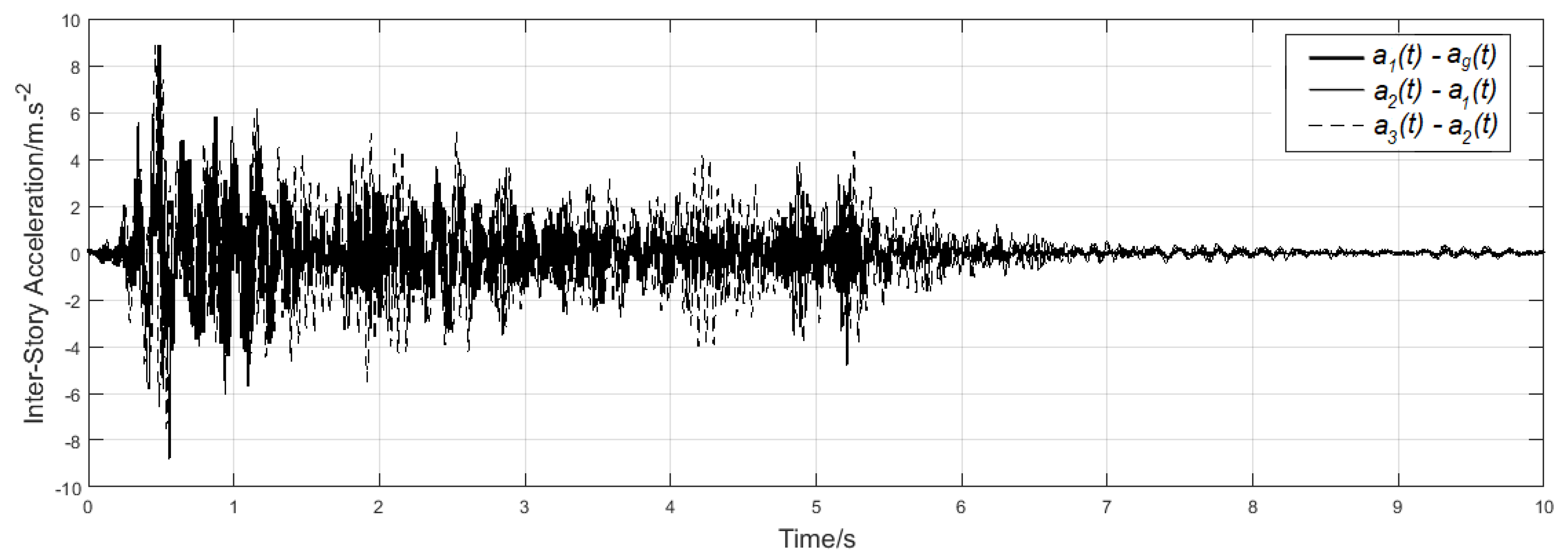
The simulation results can be observed from Figure 13, Figure 14 and Figure 15 and both the RMS and peak values are presented in Table 5. Comparing those values with the ones presented at Table 1, it was possible to see a 44% reduction on the average peak displacement value, 56.8% reduction on the RMS displacement value, 38.7% on the average peak velocity and 48.4% on its RMS value. The average peak and RMS accelerations have also been reduced by 6% and 26% respectively.
Comparing those numbers with the previous ones, is was possible to conclude that the BELBIC controller tuned using the PSO will lead to an overall improvement regarding the vibration damping characteristics of the building. In particular, comparing the ad-hoc procedure with the PSO-based one, a 16% reduction was observed on the average RMS inter-storey drift and 19% on its average peak value. Additionally, average 25% reduction in the average RMS inter-storey velocity and 23% average in inter-storey acceleration.
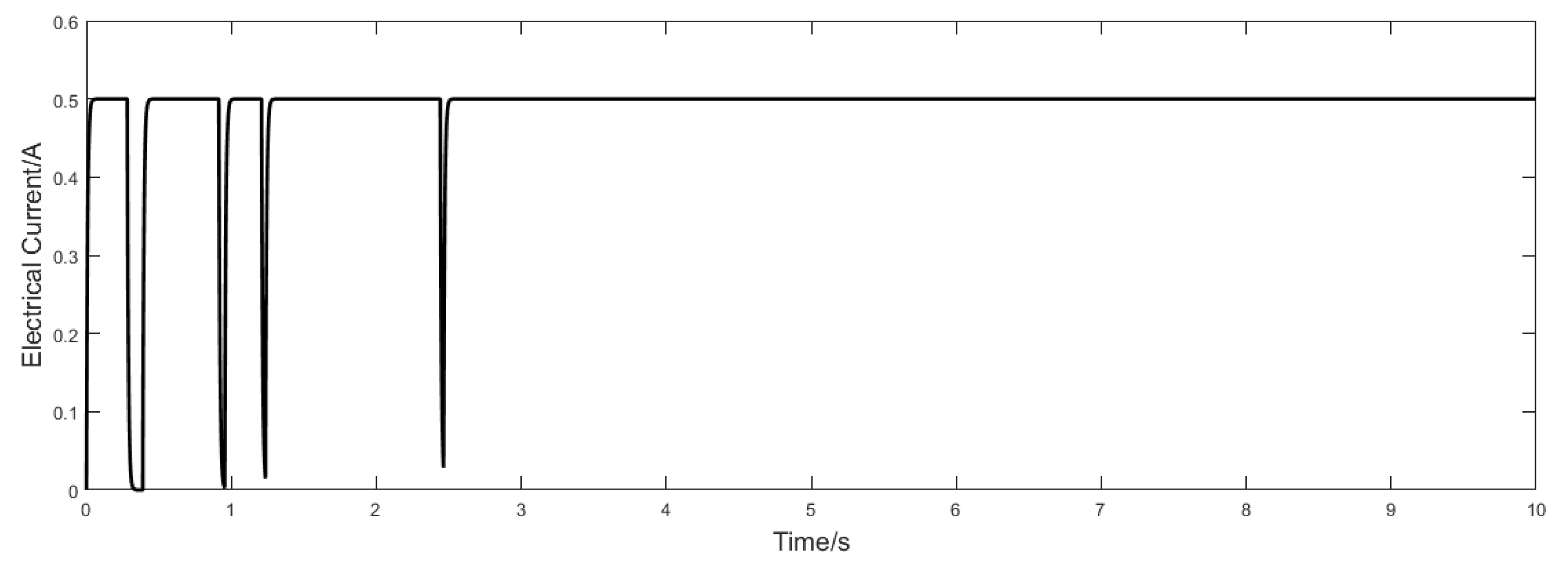
One of the problems in the ad-hoc tuning procedure was the fact that the parameters found to be suitable to reduce the building vibration have led to a high variability control signal. Using the PSO method, the simulated control signal is much more stable than the previous one as can be seen from Figure 16.
In order to illustrate the control force characteristics, Figure 17 presents the MR damper force versus its relative motion in closed-loop assuming the PSO/BELBIC controller.

Results Discussion

The use of PSO for computing the parameters of a building vibration BELBIC controller has already been explored in one of the authors previous works [17]. In the referred work, it was shown that this approach led to a set of controller parameters, that were able to outperform an empirical parameters selection method, based on trial-and-error. However, in the previously referred work, only a one-storey building was assumed which represents only a small subset of the typical civil structures. This work extends the concept of using the BELBIC, tuned with PSO, for a multiple storey building. Moreover, it has been assumed that the system possesses only one magneto–rheological actuator in the base floor which led to a non-collocated system. The control of non-collocated systems poses additional challenges, since it is required to control variable that are not directly manipulable. In this case, the top floors vibration needs to be reduced by means of changing the damping coefficient of an actuator located in the ground floor. After analyzing the obtained simulation results, it is possible to conclude that, even in this situation, the BELBIC controller provides good results and that the PSO was able to consistently derive a solution such as to minimize the vibration signal RMS value and reduce the high frequency content of the signal applied to the actuator. Presently, this control architecture has been analyzed for the case where the earthquake signal is 2D and the building is subject to vibration in the xy plane.

4. Conclusions

Being able to counteract the effect of buildings vibration under seismic disturbances is a very important task. The ability to react to those unwanted natural effects can be improved by providing ways for the structure to dynamically counteract the seismic effect. Nowadays, many state-of-the-art anti-seismic strategies involve the inclusion of magneto–rheological actuators in the building structure. This paper has addressed the problem of controlling the vibration of a non-collocated three-storey building by means of a brain–emotional controller tuned using an evolutionary algorithm. Simulation results obtained have shown that this approach leads to a 58% reduction in the peak displacement and 68% in the displacement RMS signal value. It has been shown that those values are significantly better than the ones obtained by just empirically tune the BELBIC controller. Indeed, an overall improvement of almost 20% was achieved by the PSO tuning strategy compared to the ah-hoc one. Moreover, the control signal has much less variance which is a requirement for a real-world implementation.
Taking into consideration the simulation results obtained with the present controller design method, the next step is to validate this technique using experimental data gathered from deploying this solution to a small-scale structure built over a Quanser Shake Table II system. The BELBIC controller will be embedded into a microcontroller and the system states will be measured by an array of sensors, such as accelerometers and Linear Variable Deferential Transformers (LVDT).

Author Contributions

Methodology, M.B.C.; resources, J.G.; software, J.P.C.; writing—original draft, J.P.C. and M.B.C.; writing—review and editing, J.G.

Funding

This research received no external funding.

Conflicts of Interest

The authors declare no conflict of interest.

Abbreviations

The following abbreviations are used in this manuscript:
BELBICbrain–emotional learning-based intelligent Controller
BELbrain–emotional learning
PSOparticle swarm optimization
PIDproportional, integral and derivative
MRmagneto–rheological

References

  1. Jansen, L.M.; Dyke, S.J. Semiactive Control Strategies for MR Dampers: Comparative Study. J. Eng. Mech. 2000, 126, 795–803. [Google Scholar] [CrossRef]
  2. Min, C.; Dahlmann, M.; Sattel, T. A concept for semi-active vibration control with a serial-stiffness-switch system. J. Sound Vib. 2017, 405, 234–250. [Google Scholar] [CrossRef]
  3. Lynch, J.P.; Loh, K.J.; Hou, T.C.; Wang, Y.; Yi, J.; Yun, C.B.; Lu, K.; Loh, C.H. Validation case studies of wireless monitoring systems in civil structures. In Proceedings of the 2nd International Conference on Structural Health Monitoring of Intelligent Infrastructure, Shenzhen, China, 16–18 November 2005; pp. 597–604. [Google Scholar]
  4. Loh, C.H.; Lynch, J.P.; Lu, K.C.; Wang, Y.; Chang, C.M.; Lin, P.Y.; Yeh, T.H. Experimental verification of a wireless sensing and control system for structural control using MR dampers. Earthq. Eng. Struct. Dyn. 2007, 36, 1303–1328. [Google Scholar] [CrossRef] [Green Version]
  5. Swartz, R.A.; Lynch, J.P. Partial Decentralized Wireless Control Through Distributed Computing for Seismically Excited Civil Structures: Theory and Validation. In Proceedings of the 2007 American Control Conference (ACC ’07), New York, NY, USA, 9–13 July 2007; pp. 2684–2689. [Google Scholar]
  6. Wang, Y.; Loh, C. Decentralized civil structural control using real-time wireless sensing and embedded computing. Smart Struct. Syst. 2007, 3, 321–340. [Google Scholar] [CrossRef] [Green Version]
  7. Lynch, J.P.; Wang, Y.; Swartz, R.A.; Lu, K.C.; Loh, C.H. Implementation of a closed-loop structural control system using wireless sensor networks. Struct. Control Health Monit. 2008, 15, 518–539. [Google Scholar] [CrossRef]
  8. Swartz, R.A.; Lynch, J.P. Strategic Network Utilization in a Wireless Structural Control System for Seismically Excited Structures. J. Struct. Eng. 2009, 135, 597–608. [Google Scholar] [CrossRef] [Green Version]
  9. Wang, Y.; Lynch, J.; Law, K. Decentralized H controller design for large-scale civil structures. Earthq. Eng. Struct. Dyn. 2009, 38, 377–401. [Google Scholar] [CrossRef]
  10. Law, K.H.; Wang, Y.; Swartz, A.; Lynch, J.P. Wireless sensing and vibration control of civil structures. In Proceedings of the 2010 IEEE International Conference on Wireless Information Technology and Systems, Honolulu, HI, USA, 28 August–3 September 2010. [Google Scholar]
  11. Kane, M.B.; Lynch, J.P.; Law, K. Market-based control of shear structures utilizing magnetorheological dampers. In Proceedings of the 2011 American Control Conference, San Francisco, CA, USA, 29 June–1 July 2011. [Google Scholar]
  12. Swartz, R.A. Reduced-order modal-domain structural control for seismic vibration control over wireless sensor networks. In Proceedings of the 2011 American Control Conference (ACC ’11), San Francisco, CA, USA, 29 June–1 July 2011. [Google Scholar]
  13. Soto, M.G.; Adeli, H. Multi-agent replicator controller for sustainable vibration control of smart structures. J. Vibroeng. 2017, 19, 4300–4317. [Google Scholar] [CrossRef]
  14. Winter, B.D.; Swartz, R.A. Low-force magneto–rheological damper design for small-scale structural control. Struct. Control Health Monit. 2017, 24, e1990. [Google Scholar] [CrossRef]
  15. Abé, M. Structural Monitoring of Civil Structures using Vibration Measurement—Current Practice and Future. In Artificial Intelligence in Structural Engineering; Springer: Berlin/Heidelberg, Germany, 1998; pp. 1–18. [Google Scholar]
  16. Braz-César, M.B.; Gonçalves, J.; Coelho, J.; de Barros, R.C. Brain Emotional Learning Based Control of a SDOF Structural System with a MR Damper. In Proceedings of the CONTROLO 2016, Guimarães, Portugal, 14–16 June 2016; pp. 547–557. [Google Scholar]
  17. Braz-César, M.; Coelho, J.P.; Gonçalves, J. Evolutionary-Based BEL Controller Applied to a Magneto–Rheological Structural System. Actuators 2018, 7, 29. [Google Scholar] [CrossRef]
  18. Yang, F.; Sedaghati, R.; Esmailzadeh, E. Development of LuGre friction model for large-scale magneto–rheological fluid damper. J. Intell. Mater. Syst. Struct. 2009, 20, 923–937. [Google Scholar] [CrossRef]
  19. Tsang, H.H.; Su, R.K.L.; Chandler, A.M. Simplified inverse dynamics models for MR fluid dampers. Eng. Struct. 2005, 28, 327–341. [Google Scholar] [CrossRef]
  20. Weber, F.; Maślanka, M. Precise Stiffness and Damping Emulation with MR Dampers and its Application to Semi-active Tuned Mass Dampers of Wolgograd Bridge. Smart Mater. Struct. 2014, 23, 15–19. [Google Scholar] [CrossRef]
  21. Wang, E.-R.; Ma, X.Q.; Rakheja, S.; Su, C.-Y. Force tracking control of vehicle vibration with MR-dampers. In Proceedings of the 2005 IEEE International Symposium on, Mediterrean Conference on Control and Automation Intelligent Control, Limassol, Cyprus, 27–29 June 2005; pp. 995–1000. [Google Scholar]
  22. Weber, F. Robust force tracking control scheme for MR dampers. Struct. Control Health Monit. 2015, 22, 1373–1395. [Google Scholar] [CrossRef]
  23. Pan, G.; Matsuhisa, H.; Honda, Y. Analytical model of a magnetorheological damper and its application to the vibration control. In Proceedings of the 26th Annual Conference of the Industrial Electronics Society (IECON 2000), Nagoya, Japan, 22–28 October 2000. [Google Scholar]
  24. Dalvi, B. Modelling and Testing of MR Dampers. Master’s Thesis, Coventry University, Coventry, UK, 2015. [Google Scholar]
  25. Spencer, B.F.; Dyke, S.J.; Sain, M.K.; Carlson, J.D. Phenomenological Model for Magnetorheological Dampers. J. Eng. Mech. 1997, 123, 230–238. [Google Scholar] [CrossRef]
  26. Choi, S.B.; Lee, S.K.; Park, Y.P. A hysteresis model for the field-dependent damping force of a magnetorheological damper. J. Sound Vib. 1998, 245, 375–383. [Google Scholar] [CrossRef]
  27. Yang, G. Large-Scale Magnetorheological Fluid Damper for Vibration Mitigation: Modeling, Testing and Control. Ph.D. Thesis, University of Notre Dame, Notre Dame, IN, USA, 2001. [Google Scholar]
  28. Rossi, A.; Orsini, F.; Scorza, A.; Botta, F.; Belfiore, N.; Sciuto, S. A Review on Parametric Dynamic Models of Magnetorheological Dampers and Their Characterization Methods. Actuators 2016, 7, 16. [Google Scholar] [CrossRef]
  29. Dyke, S.J.; Spencer, B.F.; Sain, M.K.; Carlson, J.D. Modeling and control of magnetorheological dampers for seismic response reduction. Smart Mater. Struct. 1996, 5, 565–575. [Google Scholar] [CrossRef] [Green Version]
  30. Weber, F.; Distl, J.; Meier, L.; Braun, C. Curved surface sliders with friction damping, linear viscous damping, bow tie friction damping and semi-actively controlled properties. Struct. Control Health Monit. 2018, 25, e2257. [Google Scholar] [CrossRef]
  31. Jiménez, R.; Alvarez-Icaza, L. LuGre friction model for a magneto–rheological damper. J. Struct. Control. Health Monit. 2005, 12, 91–116. [Google Scholar] [CrossRef]
  32. Lucas, C.; Shahmirzadi, D.; Sheikholeslami, N. Introducing Belbic: Brain Emotional Learning Based Intelligent Controller. Intell. Autom. Soft Comput. 2004, 10, 11–21. [Google Scholar] [CrossRef]
  33. Balkenius, C.; Morén, J. Emotional Learning: A computational model of the amygdala. Cybern. Syst. 2001, 32, 611–636. [Google Scholar] [CrossRef]
  34. Khorashadizadeh, S.; Mahdian, M. Voltage tracking control of DC-DC boost converter using brain emotional learning. In Proceedings of the 4th International Conference on Control, Instrumentation, and Automation, Qazvin, Iran, 27–28 January 2016; pp. 268–272. [Google Scholar]
  35. Yi, H. A Sliding Mode Control Using Brain Limbic System Control Strategy for a Robotic Manipulator. Int. J. Adv. Robot. Syst. 2015, 12, 158. [Google Scholar] [CrossRef]
  36. Sadeghieh, A.; Roshanian, J.; Najafi, F. Implementation of an Intelligent Adaptive Controller for an Electrohydraulic Servo System Based on a Brain Mechanism of Emotional Learning. Int. J. Adv. Robot. Syst. 2012, 9, 84. [Google Scholar] [CrossRef] [Green Version]
  37. Jafari, E.; Marjanian, A.; Solaymani, S.; Shahgholian, G. Designing an Emotional Intelligent Controller for IPFC to Improve the Transient Stability Based on Energy Function. J. Electr. Eng. Technol. 2013, 8, 478–489. [Google Scholar] [CrossRef] [Green Version]
  38. Javan-Roshtkhari, M.; Arami, A.; Lucas, C. Emotional control of inverted pendulum system: A soft switching from imitative to emotional learning. In Proceedings of the 4th International Conference on Autonomous Robots and Agents, Wellington, New Zealand, 10–12 February 2009. [Google Scholar]
  39. Dorrah, H.T.; El-Garhy, A.M.; El-Shimy, M.E. PSO-BELBIC scheme for two-coupled distillation column process. J. Adv. Res. 2011, 2, 73–83. [Google Scholar] [CrossRef] [Green Version]
  40. Fard, F.; Shahgholian, G.; Rajabi, A.; Habibollahi, M. Brain Emotional Learning Based Intelligent Controller for Permanet Magnet Synchronous Motor. In Proceedings of the IPEC2010, Singapore, 27–29 October 2010; pp. 989–993. [Google Scholar]
  41. Huang, G.; Zhen, Z.; Wang, D. Brain Emotional Learning Based Intelligent Controller for Nonlinear System. In Proceedings of the Second International Symposium on Intelligent Information Technology Application, Shanghai, China, 20–22 December 2008; pp. 660–663. [Google Scholar]
  42. Mohammed, M.; Bijoy, K. An Intelligent Automatic Level Controller for Speech Signals: BELBIC. In Proceedings of the IEEE International Conference on Signal Processing, Communications and Computing, Xi’an, China, 14–16 September 2011; pp. 1–5. [Google Scholar]
  43. Valikhani, M.; Sourkounis, C. A brain emotional learning-based intelligent controller (BELBIC) for DFIG system. In Proceedings of the International Symposium on Power Electronics, Electrical Drives, Automation and Motion, Ischia, Italy, 18–20 June 2014. [Google Scholar]
  44. Mei, Y.; Tan, G.; Liu, Z. An Improved Brain-Inspired Emotional Learning Algorithm for Fast Classification. Algorithms 2017, 10, 70. [Google Scholar] [CrossRef]
  45. Shahmirzadi, D. Computational Modeling of the Brain Limbic System and Its Application in Control Engineering. Ph.D. Thesis, Texas A & M University, College Station, TX, USA, 2005. [Google Scholar]
  46. Coelho, J.P.; Pinho, T.M.; Boaventura-Cunha, J.; de Oliveira, J.B. A new brain emotional learning Simulink® toolbox for control systems design. IFAC-PapersOnLine 2017, 50, 16009–16014. [Google Scholar] [CrossRef]
  47. Jafarzadeh, S.; Motlagh, M.R.J.; Barkhordari, M.; Mirheidari, R. A new Lyapunov based algorithm for tuning BELBIC controllers for a group of linear systems. In Proceedings of the 16th Mediterranean Conference on Control and Automation, Ajaccio, France, 25–27 June 2008. [Google Scholar]
  48. Garmsiri, N.; Najafi, F. Fuzzy tuning of Brain Emotional Learning Based Intelligent Controllers. In Proceedings of the 8th World Congress on Intelligent Control and Automation, Jinan, China, 7–9 July 2010. [Google Scholar]
  49. Kennedy, J.; Eberhart, R. Particle swarm optimization. In Proceedings of the 1995 International Conference on Neural Networks (ICNN’95), Paris, France, 9–13 October 1995. [Google Scholar]
  50. Eslami, M.; Shareef, H.; Khajehzadeh, M.; Mohamed, A. A Survey of the State of the Art in Particle Swarm Optimization. Res. J. Appl. Sci. Eng. Technol. 2012, 49, 1181–1197. [Google Scholar]
  51. Zhang, Y.; Wang, S.; Ji, G. A Comprehensive Survey on Particle Swarm Optimization Algorithm and Its Applications. Math. Probl. Eng. 2015, 2015, 1–38. [Google Scholar] [CrossRef]
  52. Eberhart, R.C.; Shi, Y.; Kennedy, J. Swarm Intelligence; Academic Press: San Diego, CA, USA, 2001. [Google Scholar]
  53. Shi, Y.; Eberhart, R.C. Parameter selection in particle swarm optimization. In Evolutionary Programming VII. EP 1998; Springer: Berlin/Heidelberg, Germany, 1998; pp. 591–600. [Google Scholar]
  54. Pedersen, M.E.H. Good Parameters for Particle Swarm Optimization; Technical Report HL1001; Hvass Laboratories: Copenhagen, Denmark, 2010. [Google Scholar]
  55. Mezura-Montes, E.; Coello, C.A.C. Constraint-handling in nature-inspired numerical optimization: Past, present and future. Swarm Evol. Comput. 2011, 1, 173–194. [Google Scholar] [CrossRef]
  56. Valizadeh, S.; Jamali, M.R.; Lucas, C. A particle-swarm-based approach for optimum design of BELBIC controller in AVR system. In Proceedings of the International Conference on Control, Automation and Systems, Seoul, Korea, 14–17 October 2008; pp. 2679–2684. [Google Scholar]
  57. Jafari, M.; Shahri, A.M.; Elyas, S.H. Optimal tuning of Brain Emotional Learning Based Intelligent Controller using Clonal Selection Algorithm. In Proceedings of the 3th International eConference on Computer and Knowledge Engineering (ICCKE), Mashhad, Iran, 31 October–1 November 2013. [Google Scholar]
  58. Valipour, M.H.; Maleki, K.N.; Ghidary, S.S. Optimization of Emotional Learning Approach to Control Systems with Unstable Equilibrium. In Software Engineering, Artificial Intelligence, Networking and Parallel/Distributed Computing; Springer: Cham, Switzerland, 2015; pp. 45–56. [Google Scholar]
  59. El-Saify, M.H.; El-Garhy, A.M.; El-Sheikh, G.A. Brain Emotional Learning Based Intelligent Decoupler for Nonlinear Multi-Input Multi-Output Distillation Columns. Math. Probl. Eng. 2017, 2017, 8760351. [Google Scholar] [CrossRef]
  60. César, M.T.B. Vibration Control of Building Structures Using MagnetoRheological Dampers. Ph.D. Thesis, Faculty of Engineering of the University of Porto, Porto, Portugal, 2015. [Google Scholar]
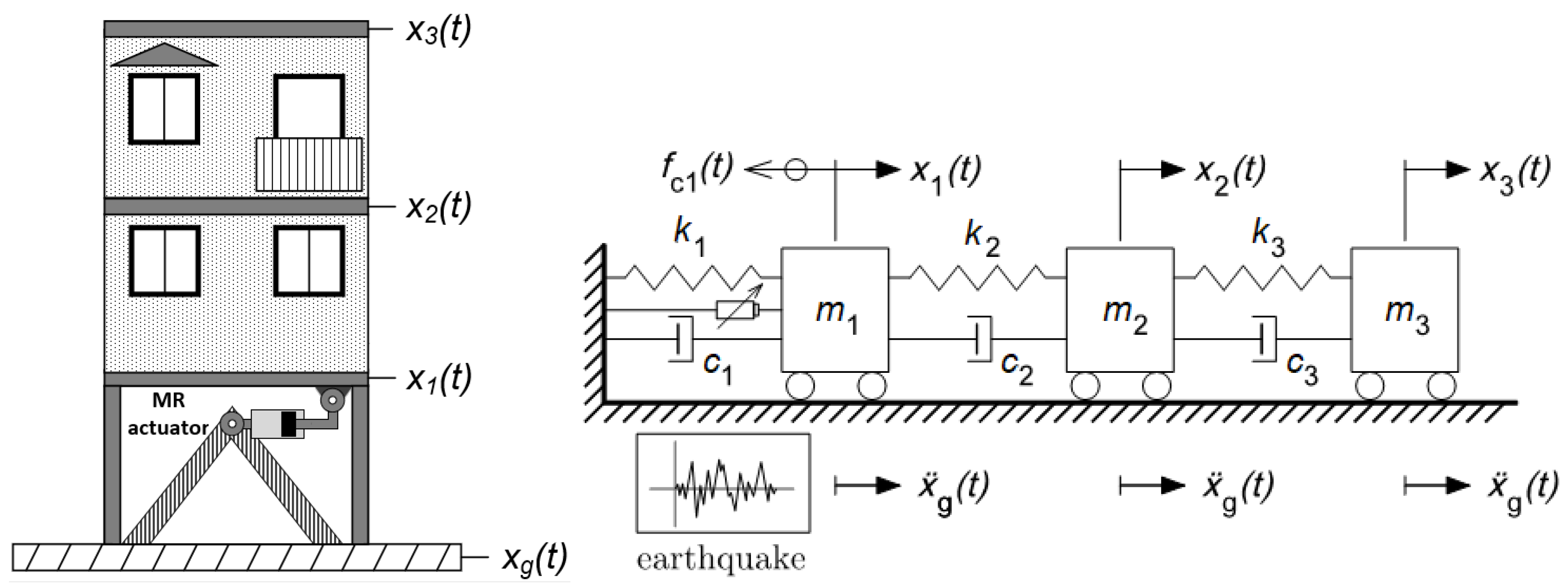
Figure 1. Building magneto–rheological (MR) actuator location (left) and lumped elements equivalent model (right).
Actuators 08 00043 g001
Figure 2. North–south ground motion acceleration component from the El-Centro earthquake.
Actuators 08 00043 g002
Figure 3. Lumped elements equivalent model for a magneto–rheological damper.
Actuators 08 00043 g003
Figure 4. Brain–emotional learning model block diagram.
Actuators 08 00043 g004
Figure 5. The brain–emotional learning-based intelligent control (BELBIC) control architecture for the three-storey building vibration control.
Actuators 08 00043 g005
Figure 6. The inter-storey drift dynamic response of the building, without MR damper, to the earthquake signal represented at Figure 2.
Actuators 08 00043 g006
Figure 7. The relative velocity of the structure, without MR damper, when excited with the earthquake signal.
Actuators 08 00043 g007
Figure 8. The relative acceleration of the building, without MR damper, when excited with the earthquake signal.
Actuators 08 00043 g008
Figure 9. The building closed-loop displacement response to the earthquake, assuming an empirically tuned BELBIC controller.
Actuators 08 00043 g009
Figure 10. The building closed-loop velocity response to the earthquake, assuming an empirically tuned BELBIC controller.
Actuators 08 00043 g010
Figure 11. The building closed-loop acceleration response to the earthquake, assuming an empirically tuned BELBIC controller.
Actuators 08 00043 g011
Figure 12. Control signal generated by the empirically tuned BELBIC. The top plot regards a total time of 10 s and the bottom plot, a narrower interval.
Actuators 08 00043 g012
Figure 13. Inter-storey drift, under seismic excitation, using the particle swarm optimization (PSO)/BELBIC controller.
Actuators 08 00043 g013
Figure 14. Inter-storey velocity, under seismic excitation, using the PSO/BELBIC controller.
Actuators 08 00043 g014
Figure 15. Inter-storey acceleration, under seismic excitation, using the PSO/BELBIC controller.
Actuators 08 00043 g015
Figure 16. Control signal generated by the PSO/BELBIC control strategy.
Actuators 08 00043 g016
Figure 17. MR force versus its relative motion when operating in closed-loop using a PSO/BELBIC controller.
Actuators 08 00043 g017
Table 1. Root mean square values (RMS) and peak values for inter-storey drift, velocity and acceleration without magneto–rheological (MR) actuator.
Inter-storey drift/cm x 1 ( t ) x g ( t ) x 2 ( t ) x 1 ( t ) x 3 ( t ) x 2 ( t )
RMS0.1260.1040.059
Peak Value0.5190.4430.292
Inter-storey velocity/ms 1 v 1 ( t ) v g ( t ) v 2 ( t ) v 1 ( t ) v 3 ( t ) v 2 ( t )
RMS0.04470.03740.0235
Peak Value0.20.1630.130
Inter-storey acceleration/ms 2 a 1 ( t ) a g ( t ) a 2 ( t ) a 1 ( t ) a 3 ( t ) a 2 ( t )
RMS1.81.571.40
Peak Value9.998.079.27
Table 2. BELBIC controller parameters empirically estimated.
α β V V th W v 1 v 2 v 3 v u w 1 w 2 w 3 w u
0.80.51.50−0.522212221
Table 3. Closed-loop RMS and peak values assuming an ad-hoc tuned brain–emotional learning-based intelligent control (BELBIC) controller.
Inter-storey drift/cm x 1 ( t ) x g ( t ) x 2 ( t ) x 1 ( t ) x 3 ( t ) x 2 ( t )
RMS0.05380.0580.037
Peak Value0.3190.3230.224
Inter-storey velocity/ms 1 v 1 ( t ) v g ( t ) v 2 ( t ) v 1 ( t ) v 3 ( t ) v 2 ( t )
RMS0.02220.02740.0232
Peak Value0.1570.1620.126
Inter-storey acceleration/ms 2 a 1 ( t ) a g ( t ) a 2 ( t ) a 1 ( t ) a 3 ( t ) a 2 ( t )
RMS1.781.461.38
Peak Value9.988.019.21
Table 4. BELBIC controller parameters obtained using particle swarm optimization (PSO).
α β V V th W v 1 v 2 v 3 v u w 1 w 2 w 3 w u
00−2−2−200000000
1122222222222
0.4360.01011.990.6391.990.00020.000180.00010.04781.3070.9620.4951.985
Table 5. Closed-loop RMS and peak values assuming an PSO tuned BELBIC controller.
Inter-storey drift/cm x 1 ( t ) x g ( t ) x 2 ( t ) x 1 ( t ) x 3 ( t ) x 2 ( t )
RMS0.04420.04990.0307
Peak Value0.2400.2770.177
Inter-storey velocity/ms 1 v 1 ( t ) v g ( t ) v 2 ( t ) v 1 ( t ) v 3 ( t ) v 2 ( t )
RMS0.01670.02060.0172
Peak Value0.08850.1220.0918
Inter-storey acceleration/ms 2 a 1 ( t ) a g ( t ) a 2 ( t ) a 1 ( t ) a 3 ( t ) a 2 ( t )
RMS0.9521.2911.28
Peak Value8.8797.988.823