Article

Electromechanical Actuation for Morphing Winglets

by
Ignazio Dimino
1,*,
Federico Gallorini
2,
Massimiliano Palmieri
3 and
Giulio Pispola
3
1
CIRA, The Italian Aerospace Research Centre, Department of Adaptive Structures, Via Maiorise, 81043 Capua (CE), Italy
2
Viola Consulting srl, Via dell’Arte, 26 06053 Deruta (PG), Italy
3
Umbragroup SpA, Via V.Baldaccini, 1 06034 Foligno (PG), Italy
*
Author to whom correspondence should be addressed.
Actuators 2019, 8(2), 42; https://doi.org/10.3390/act8020042
Submission received: 25 February 2019 / Revised: 24 April 2019 / Accepted: 3 May 2019 / Published: 15 May 2019

Abstract

:
As a key enabler for future aviation technology, the use of servo electromechanical actuation offers new opportunities to transition innovative structural concepts, such as biomimicry morphing structures, from basic research to new commercial aircraft applications. In this paper, the authors address actuator integration aspects of a wing shape-changing flight surface capable of adaptively enhancing aircraft aerodynamic performance and reducing critical wing structural loads. The research was collocated within the Clean Sky 2 Regional Aircraft Demonstration Platform (IADP) and aimed at developing an adaptive winglet concept for green regional aircraft. Finite Element-based tools were employed for the structural design of the adaptive device characterized by two independent movable tabs completely integrated with a linear direct-drive actuation. The structural design process was addressed in compliance with the airworthiness needs posed by the implementation of regional airplanes. Such a load control system requires very demanding actuation performance and sufficient operational reliability to operate on the applicable flight load envelope. These requirements were met by a very compact direct-drive actuator design in which the ball recirculation device was integrated within the screw shaft. Focus was also given to the power-off electric brake necessary to block the structure in a certain position and dynamically brake the moveable surface to follow a certain command position during operation. Both the winglet layout static and dynamic robustness were verified by means of linear stress computations at the most critical conditions and normal mode analyses, respectively, with and without including the integrated actuator system.

1. Introduction

Morphing wings have the greatest ambition to significantly alter design and operation of future generations of aircraft [1,2,3,4,5,6]. Their ability to change the wing geometry and reconfigure themselves in multiple shapes in order to match specific flight conditions at the best may dramatically contribute to tackle some of aviation’s biggest environmental challenges including fuel efficiency, noise, and emissions. Some mechanical control surfaces such as flaps, ailerons, rudders, already provide aircraft with some basic adaptation capabilities by changing their geometry and varying the local camber. Morphing philosophy tries to extend such capabilities in a more combined and efficient perspective within the entire flight envelope with the aim of providing aircraft with a form of continuous geometry variations to improve aerodynamic efficiency and optimize performance.
Morphing wing technology may be categorized according to two alternative design paradigms: compliant and kinematic architectures. In the former, the structure is designed to achieve specific aeroshapes through careful material distribution while resisting the external loads [7,8]. In kinematic architectures, the structure is articulated in different rigid parts moving according to a pre-defined mechanical law [9,10]. A morphing skin enveloping the skeleton preserves a regular geometry during shape adaptation. In both cases, the system is moved by inner actuators through defined mechanisms which contribute to withstand the external loads. Compared to rigid-body mechanisms, whose discontinuities may affect wing aerodynamic efficiency, compliant structures allow smoother and more controllable morphing wing shapes without suffering from the characteristic problems of kinematic chains, such as concentrated forces at the joints, backlash, friction, etc. On the other hand, by relying upon concentrated compliance instead of conventional joints, compliant structures require an extra actuation authority to deform themselves to the desired configuration under the action of inner actuators [11,12]. Furthermore, compliant structures scale better than mechanisms by tailoring, for instance, the equivalent hinges’ length and thickness to exhibit the same structural behavior at different scales.
Several projects have been launched in recent years in Europe to develop and assess new technologies to reduce aircraft fuel burn through better aerodynamic performance enabled by wing shape changes and light-weight structural design [13,14,15,16,17,18]. Among the most promising, adaptive morphing trailing edge wing concepts have been shown to reduce the fuel burn of medium-range transport aircraft by 6% or greater and significantly alleviate gust and maneuver loads in combination with adaptive winglets [19]. Additionally, morphing winglets may provide enhanced Lift over Drag ratio during climb, and, more generally, in off-design conditions through a variable trailing edge control. As in off-design conditions, in particular, climb and descent phases represent a crucial flight segment for regional aircraft, and non-optimal configurations lead to remarkable operational penalties which require specific attention.
Despite the considerable research, however, with evidence supporting the potential for increased aerodynamic efficiency, maneuverability, and control effectiveness, shape-changing wing structures still suffer from a lack of tailored actuation solutions which optimally face a number of design challenges: reduced weight, volume, and complexity of power transmission paths, optimal force transmission, aeroelastic impact of the augmented DOF (degrees of freedom) system, higher modal density and more critical behavior than conventional surfaces, energy requirements and dissipation needs, etc. Additionally, actuation layout assumes a crucial significance for a reversible shape and deformation control, and its failure leads to more extensive uncertainties in such more complex structures.
Smart actuation is a viable option to produce high forces within small accessible rooms [20,21]. Shape-memory alloy actuators are increasingly becoming a focus of interest for morphing wing applications, but they are still not mature enough for integration into actual aircraft systems. The use of active elements may further make the structural design more complex by modifying stiffness, mass and damping value, and distribution of the morphing structure.
The main goal of this study is to investigate the main challenges in the development and integration of electromechanical actuator (EMA) technology for future morphing wing applications. In the framework of the CleanSky 2 Airgreen 2 project [22], this paper focuses on the safety-driven design of a morphing winglet concept specifically tailored for EASA CS-25 category aircraft for wing load control and root bending moment alleviation. The main design challenges that may be encountered to accommodate a suitable electromechanical actuator in such a confined space are explored. Focus is given to the study of the actuator performance and the structural impact of the whole actuation chain on the morphing winglet tabs. Such an approach assumes that, in principle, a flight-worthy actuator of adequate size, weight, and power will be developed to withstand the hinge moments due to the aerodynamic loads, especially when the control surfaces are deflected downwards. However, it is reasonable to expect that the actual aeroshapes of a mechanically-driven morphing architecture would be strongly influenced by the stiffness of the entire actuation chain, with significant implications on the static and dynamic structural response. In order to check the validity of these considerations, the authors present detailed numerical investigations, thus establishing safe design domains for the structural layout of both the movable tabs and related actuation lines.

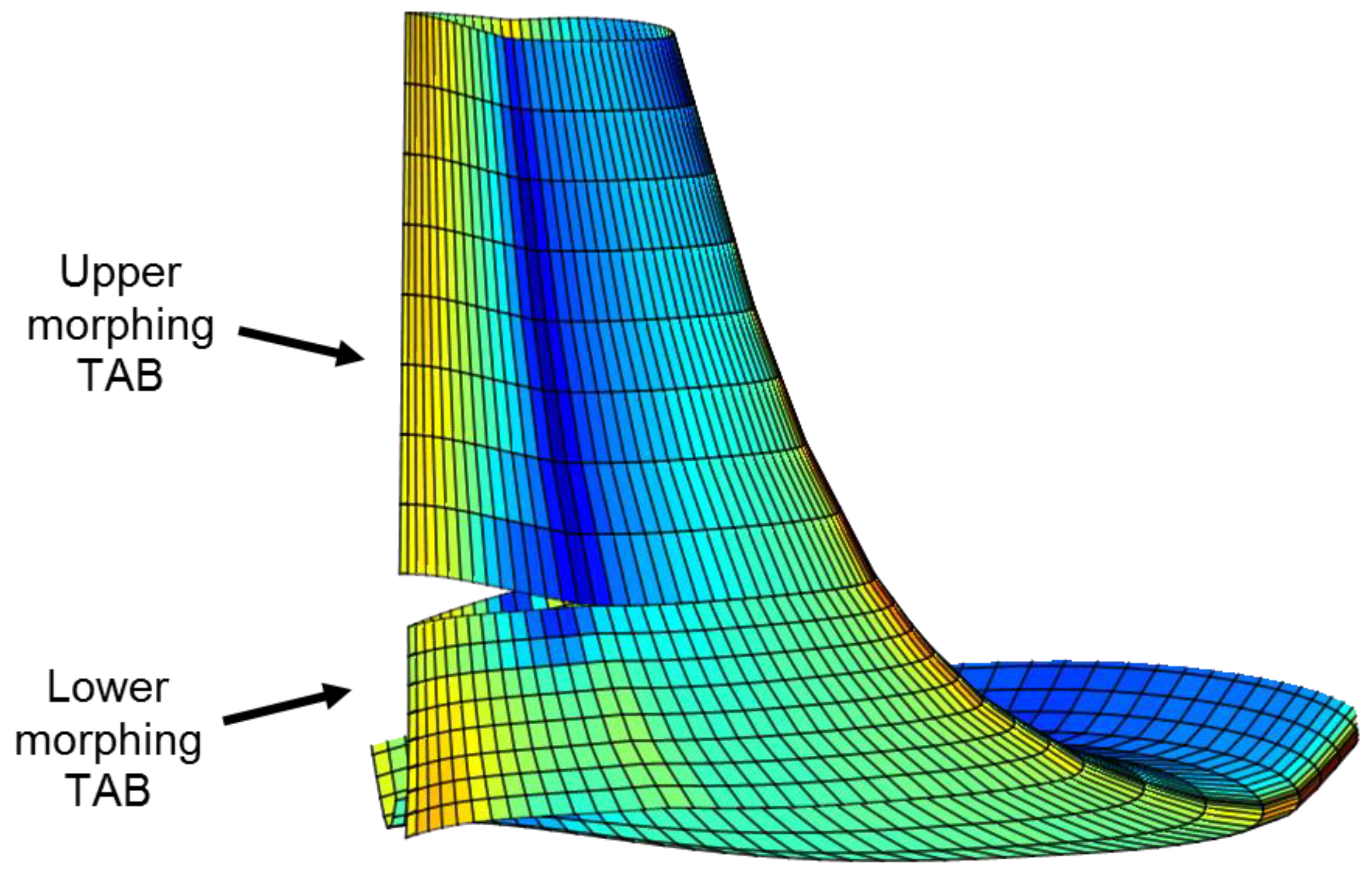
2. Morphing Winglet Concept

Aircraft winglets are a proven way to enhance aircraft performance and reduce fuel consumption by enabling higher lift over drag ratios and lower induced drag. Since the earliest-known concepts, the fuel burn improvement with blended winglets at the airplane’s design range was on the order of 6% [23] and the enabled aircraft steeper angles of attack contributed to reduce takeoff distances. The addition of winglets installed by retrofit increases also the aircraft payload/range capability by the same order of the fuel burn savings, although significant changes in the wing structure may be necessary. More recently, such pioneering installations are increasingly becoming a topic of research for the purpose of lowering wing bending moments and increasing aircraft flight stability through morphing technology. Several morphing winglet concepts have been patented [24,25], or are being developed to further lower aircraft operating costs by reducing block fuel burn by 4–5% through adaptive winglet geometries in return to changing flight conditions. With the rapid advances of more/all electric technology, electromechanically actuators have become gradually mature to be introduced in commercial transport aircraft. They offer significant opportunities also for morphing winglets applications to alleviate gust loads and control the wing lift distribution over the wing span by adaptively modifying the winglet leading or trailing edges through inner morphing mechanisms. In order to actively control both aerodynamic loads and root bending moments (RBMs), a full-scale carbon-fiber reinforced-plastic (CFRP) winglet was developed, for instance, in the framework of SARISTU [26]. A morphing skin enabled a smooth shape transition between the fixed and movable winglet portions by eliminating the interference between the wing and the winglet surface.
In this paper, detailed numerical investigations were implemented for the characterization and integration of an electromechanically-based actuation into a finger-like mechanism-based morphing winglet. Apart from the aerodynamic benefits resulting from such a morphing device, estimated on the order of 2.5% LoD at high CL with respect to the optimal passive winglet counterpart [8], this approach ensures smoother morphing winglet aeroshapes and a more efficient distribution of the span-wise aerodynamic loading estimated by CFD simulations (Figure 1). Hinged mechanisms were implemented at the trailing edges to realize the morphing layout of two tabs, which can be independently deployed both upward and downward. One of the major advantages of this architecture is the capability to move the individual surfaces either synchronously or independently to different angles. Such a “finger-like” mechanism was co-developed by the first author in the past and successfully validated on full-scale morphing wing trailing edge and aileron devices [27,28].
The upper- and lower-morphing mechanisms consist of three consecutive hinge-connected blocks (B0, B1, B2), whose relative rotations enable the trailing edge camber morphing (Figure 2). Each block is covered by segmented skins connected by a spar box. The B0 block is rigidly connected to the rear spar of the winglet structure. The inner actuator drives the B1 block to rotate around its hinge system and blocks the system while deployed. The actuation rods are particularly important (and critical) in this kind of architecture, bearing the majority of the incoming loads. The resulting system is a 1-degree-of-freedom architecture (SDOF) having a specific gear ratio depending upon the mechanical hinges and links positions. The upper region of the structural box of the winglet is also shown in Figure 3. The two actuators, driving the lower- and upper-morphing tabs, respectively, were initially modelled as lumped masses. The aluminum segmented skin was divided into separate plates, two for each block for both the lower and the upper tabs, attached to the respective edges of the machined ribs and along the associated spars.

Morphing Tabs Mechanisms

The simplest way to simulate wing morphing mechanisms at the preliminary stages of the design is to assume the mechanical components as fully rigid (Figure 4). This allows designers to develop the kinematics and validate linkage dimensions, hinges positions, and instant centers of rotations, for the initial structural sizing of the components. As a result, the hinges of the finger-like mechanisms were thus FE modelled by rigid connections by releasing the rotational degree of freedom activated by morphing. The sole purpose of these elements was to transfer the loads between the grid points in such a way that all the slave (dependent) nodes had zero relative deformation after the load application. In such a way, one cannot observe any oval effect of hole or any bearing loaded pattern on the holes.
As preliminary check of the actual aeroshapes that may be reached by the morphing mechanism, a normal mode analysis was then carried out. A free-floating condition, also called free play failure, was simulated by neglecting the entire actuation chain stiffness consisting of both the actuators and actuation kinematics of the morphing tabs. Such an uncontrolled dynamic motion occurs when the actuator floats with zero moment and does not contribute to the control of the surface due to some internal failure. An example of a float failure is the loss of the electromechanical actuator causing it to move freely without producing any effective moment along the main hinge axis. Such a condition, occurring at 0.9 Hz for the upper-morphing tab kinematics, is usually referred to as morphing mode, as it is fully representative of the rigid body motion of the designed mechanism. The resulting mode shape is shown in Figure 5 along with the undeformed tab model. Theoretically, that value should equal zero; its deviation is due to the coarse FE mesh that turns into an imperfect alignment of the hinges whose effect is to rise the first “rigid” mode to a non-null value (addition of a constraint).

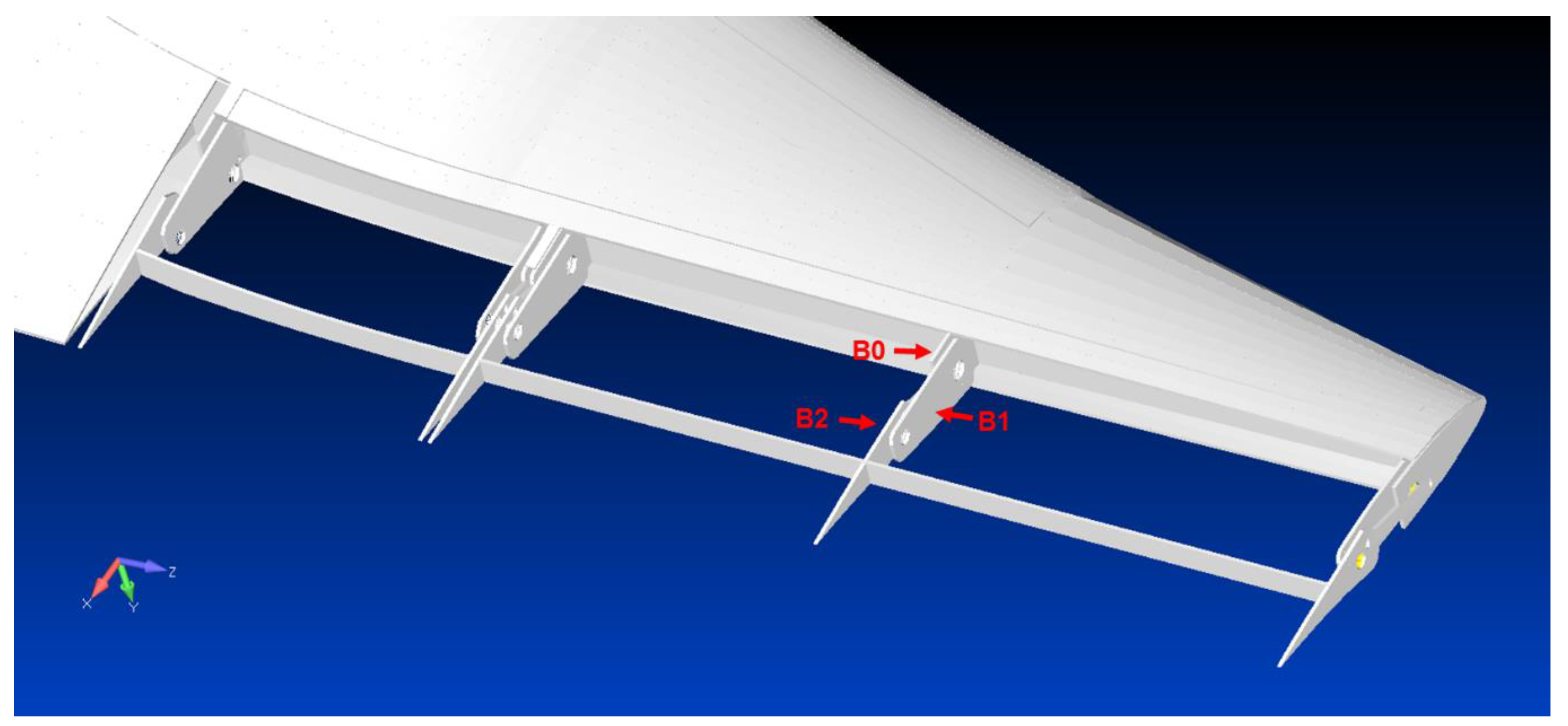
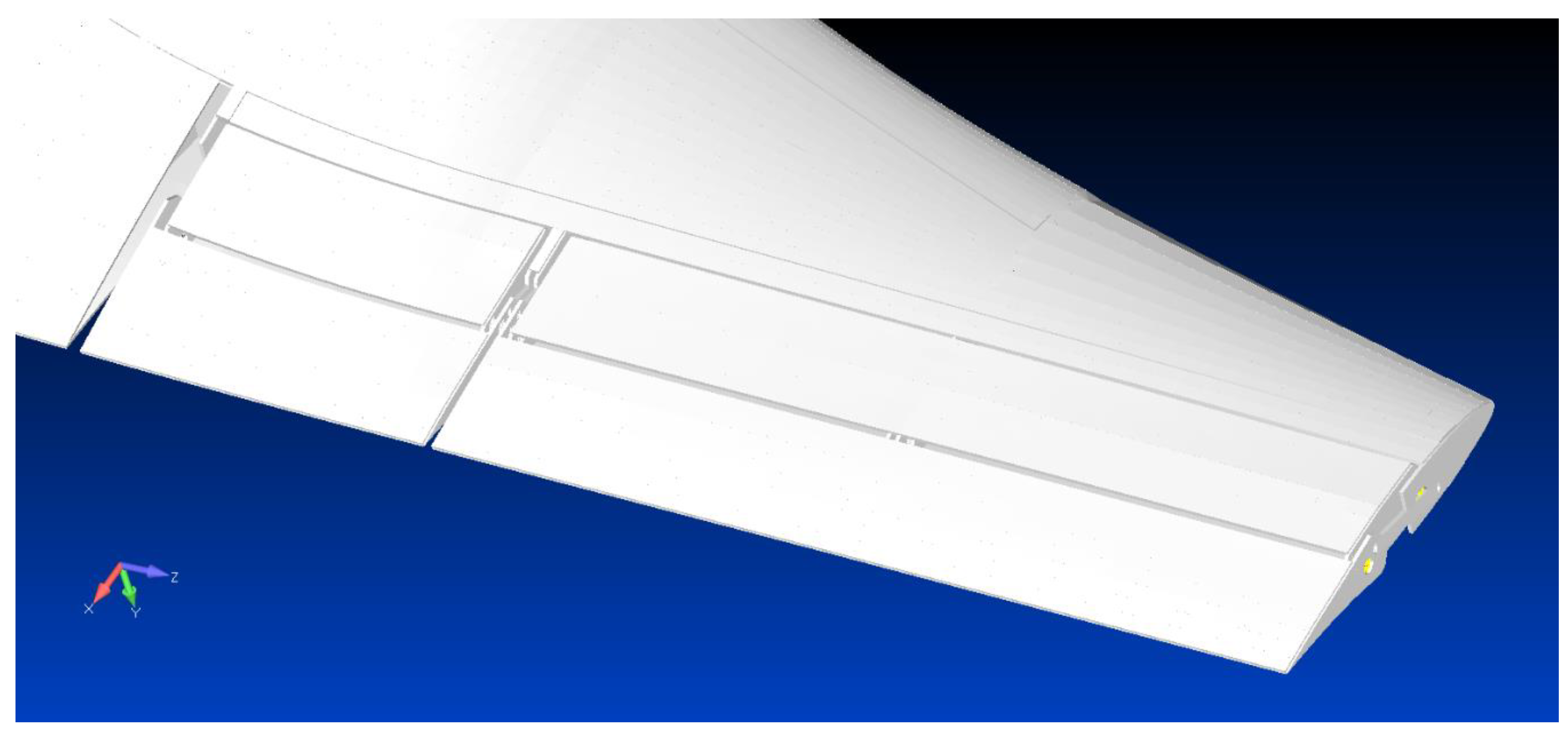
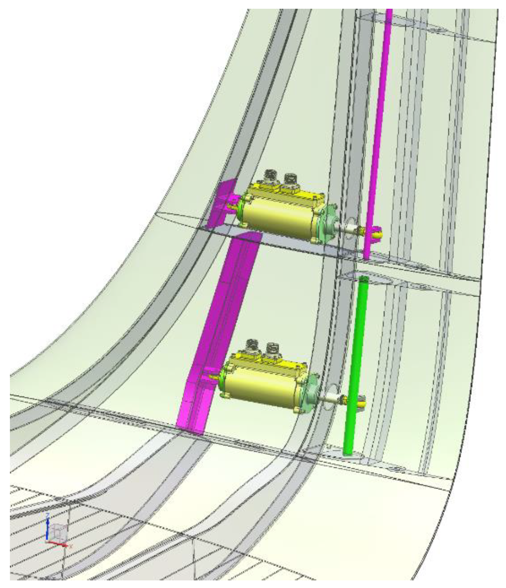
3. Actuators and Kinematics Integration

3.1. Electromechanical Actuation Concept

In order to avoid dealing with hydraulics, linear electromechanical actuation (EMA) was envisaged for the mechanical drive system. The design of the kinematic chain strongly affects the actuator requirements in terms of available space, axial and radial operating load, axial and radial static load, stroke, and speed. For this reason, starting from the basic need to move two different surfaces on the same wing independently, several installation trade-off studies were performed in order to achieve the best configuration for winglet actuators.
The kinematic chain proposed in this work was based on two separate actuators, one for each surface, positioned at different winglet height (see Figure 6). Such a solution minimized potential actuator assembly and integration issues by privileging accessibility and maintenance. The control units were installed within the nearly horizontal part of the winglet box with the aim to reduce the bending moment applied to the wings.
This direct kinematic chain, based on a crankshaft solution, enables higher construction and installation simplicity, lower weight, and higher stiffness. After some sensitivity analyses, the enveloping loads causing the highest internal solicitations on the morphing winglet, were found in dynamic lateral gust conditions at level flight in combination with aircraft maneuver and static gust design limits. For the given geometrical parameters of this kinematic chain, the actuators’ performance requirements were then derived (see Table 1). Operating and maximum static axial load were about 3.5 and 5 kN, respectively. The maximum speed foreseen for the load control function was 5 mm/s.

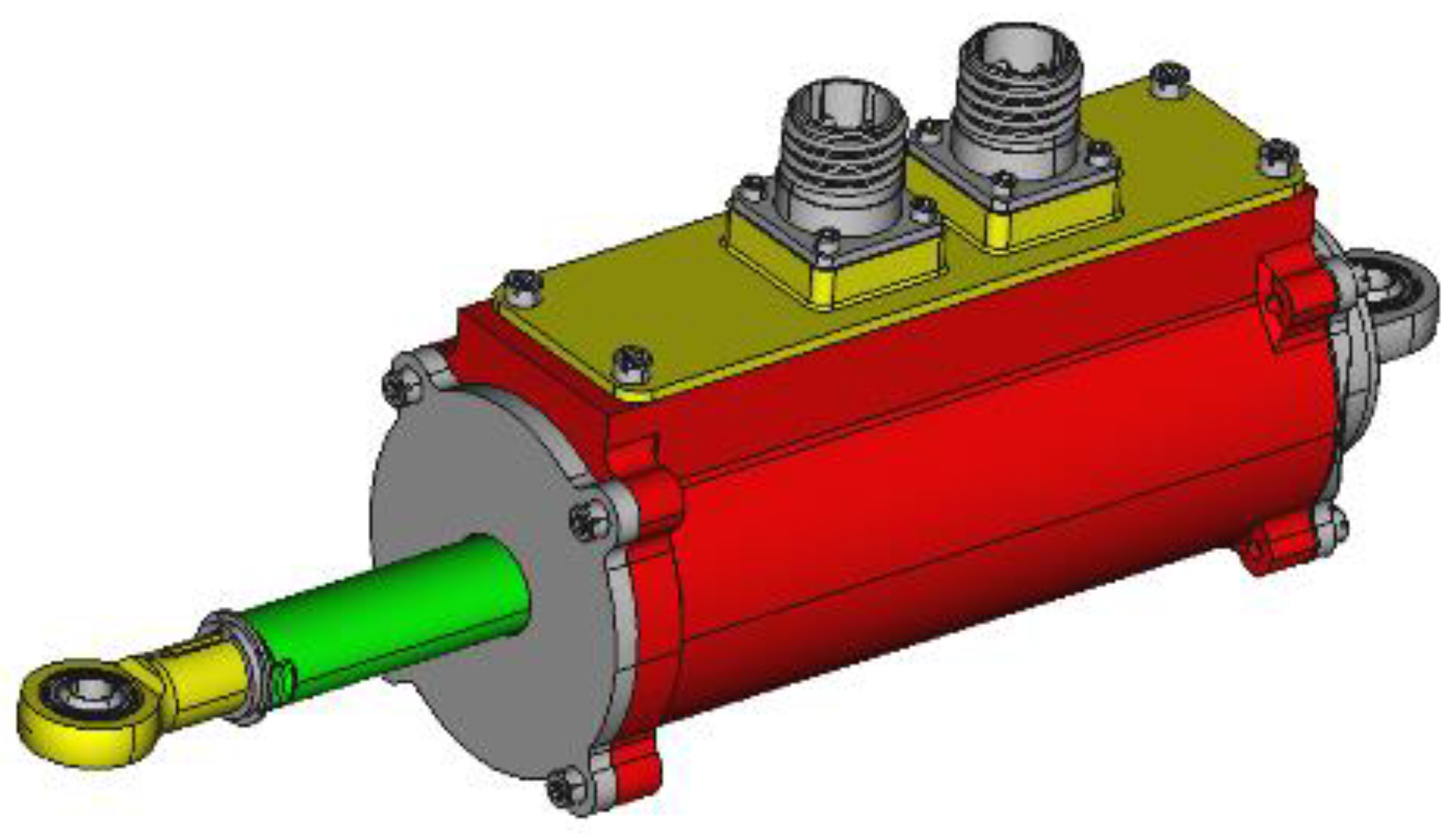
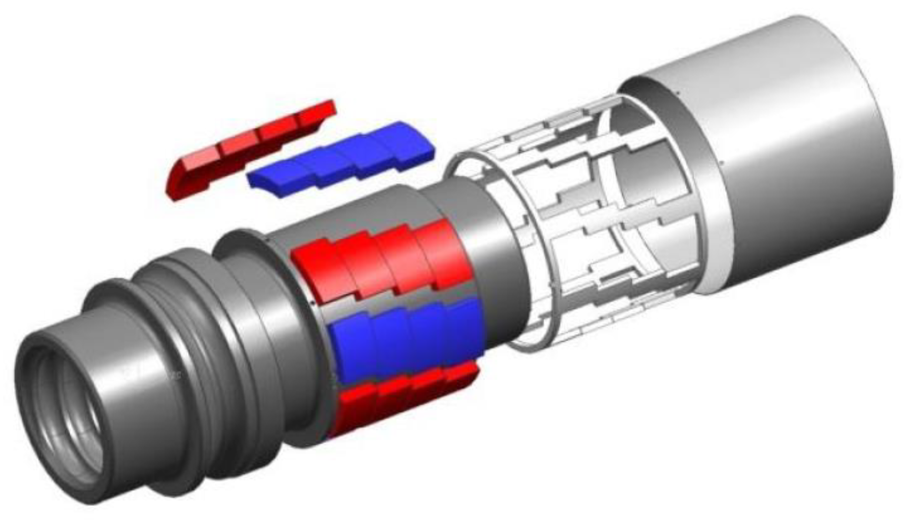
3.2. Electromechanical Actuators’ Components

Considering what said above in terms of required performance and the very limited available space envelope and admissible weight, the main focus of the research was to achieve augmented power-to-weight ratio.
The winglet actuators (Figure 7) were composed of a ballscrew with a rotating ball-nut and a translating screw shaft actuated by a permanent magnet brushless motor. The EMAs were also equipped with a power-off electric brake, wear ring, angular contact bearing, and linear position sensor. The electronic control unit (ECU) provided power to the EMA motor and controlled it through the use of hall sensors and the linear variable differential transformer (LVDT) feedback.
Aiming at minimization of the envelope and weight, the EMAs were characterized by a direct-drive configuration in which the magnets were bonded directly onto the ball-nut. Figure 8 shows a ball-nut with the magnets glued onto the outer diameter (OD) of the ball-nut and the tube that kept the magnets in position (fault-tolerant solution in case the glue failed). In this configuration the internal ring of the ball bearings was integral to the ball-nut.
The main advantages of a direct-drive solution with respect to the “geared” one are:
Low reflected inertia from the motor rotor to the load due to the low gear ratio;
Small number of components for greater reliability and easier assembly;
High efficiency due to the lower number of transmission stages;
Thermal stability;
Reduced maintenance;
Reduced noise due to absence of gears and reduced friction between the ball-nut, balls; and screw shaft;
Increased accuracy due to the lower number of transmission stages;
Reduced irreversibility load;
Lower backlash.
The compact design and the direct-drive configuration were possible thanks to a new design for the ballscrew in which the ball recirculation device was an integrated part of the screw shaft. This represents a more reliable configuration because of the lower number of parts and that it had a smaller diameter and shorter length than other ballscrew configurations. Moreover, an anti-rotation device was integrated into the EMA by means of an elliptic coupling between the screw shaft and the housing, such that the ballscrew system could only translate when the ball-nut was rotated. This feature allowed to avoid the use of a dedicated or external device for the anti-rotation, but required a bigger design effort on the evaluation of the wear of the bushing device and on the elliptical seals.
A general comparison with a standard direct-drive EMA configuration, in which the assembly is composed by stator, rotor, and ballscrew mechanically linked to the rotor is reported in Table 2. Operational points for the two actuators, in which the power-to-weight/volume ratios were calculated, were selected with comparable motor efficiency (90%). Obviously, the following results were obtained considering the volume and weight of only the motor and ballscrew assembly. As evident, the benefits of the proposed configuration are relevant in particular in terms of the power-to-volume ratio.
With regards to electric motors, electric steels lead in terms of market share in soft magnetic materials [29]. However, alloys based on inter-metallic compounds exhibit superior soft and hard magnetic properties [30,31]. Among the commercial magnetic materials, alloys based on the inter-metallic compound FeCo show the highest saturation magnetization [32]. In addition, they have high Curie temperatures, good permeability, good strengths, and are ideally suited for applications requiring high-flux density. However, their widespread applications are restricted due to the high cost of Co. Currently, FeCo alloys are used in applications where their high saturation values provide an advantage in reducing weight or volume of the components (e.g., aeronautics applications). This alloy is deeply investigated in the framework of research projects for the new generation of aircrafts called “more electric aircraft” [22].
Regarding these specific applications, research activities were focused on the comparison between the use of iron–silicon or iron–cobalt in the stator, keeping the Fe–Si alloy for the rotor. All studies were performed with the same geometry, adapting the number of coils when necessary.
Figure 9 shows the winglet performance comparison between FeCo and FeSi stators. These results were obtained through an electromagnetic FEM transient analysis performed to characterize the motor torque capacity in function of different currents and considering the materials’ saturation. Since the current to be used was limited to avoid a demagnetization effect (up to 4 A), the benefits of the Fe–Co material were not relevant. This was due to the low magnetic load of the motor. Both materials guarantee full coverage of the required operating points and did not induce any demagnetization effect, even considering the maximum load case. Moreover, considering the thermal class of the insulators used, both materials ensure that temperature limits were not exceeded. Finally, considering the cost versus benefits analysis (Fe–Co costs about twenty times that of Fe–Si and typical procurement times are much longer for Fe–Co laminations), it was decided to use the Fe–Si laminations.
Electromechanical actuators designed for aeronautical applications, and especially for flight control applications, are generally equipped with electromechanical brake devices [33]. The main reason that pushes towards the adoption of this type of devices is due to the mode of operation that the actuator must perform during its life cycle. In fact, electromechanical actuators installed on movable surfaces are generally required to stop the surface in a certain position and in parallel to dynamically brake the surface to follow a certain command position of the surface itself [34,35].
Different types of brakes are available on the market; however, only two types of brakes are generally used for this type of application: static brakes and dynamic brakes. The first one, provided with an anchor with teeth, allows the surface to be braked in a certain position but only after the motion of the actuator has stopped. The main advantage that this type of brake has is that it can deliver high braking torque in a limited space envelope, although they operate in static conditions. Conversely, being equipped with friction disks, dynamic brakes are capable to slow down the motion of the actuator dynamically. In fact, they can be engaged and/or actively disengaged without the need to stop the actuator first. At the same time, however, the braking torque that can be supplied by these types of brakes is lower than that of static brakes having similar dimensions.
Whatever the category, both can be of the power-on or power-off type, i.e., they can brake the actuator and, therefore, the surface with or without power supply.
A power-off clutch disc brake was selected for the winglet application. In fact, while on the one hand, the required braking torque was not excessively high, on the other hand it was necessary to have high dynamic properties. Moreover, since the surface was only deployed during the climb phase (landing gear up) with the exclusion of the take off, approach, and landing phases, the brake should be active during most of the flight time. For this reason, a power-off solution was preferred.
Figure 10 shows a schematic drawing of the brake. It consisted of four basic elements: a solenoid, an anchor (pressure plate), springs, and a friction disk. Operation was relatively simple. When the solenoid was not powered, the springs press the anchor against the friction disks, thus generating a braking torque. When it was required to disengage the brake, the powered solenoid generated a magnetic force that pulled the anchor towards itself, effectively detaching the anchor from the friction disks, thus allowing the actuator to move.
During the design phase, two aspects had to be managed: the force delivered by the solenoid had to be greater than the spring force exerted by the springs and the braking torque developed by the clutch disks had to block the loaded structure in a certain position.
The results obtained in the design phase of the electromagnetic brake were compared to those obtained during a preliminary test carried out on a mock-up of similar sizing in order to characterize the brakes. Figure 11 shows a comparison between the electromagnetic strength of the solenoid obtained through a finite element analysis and the ones obtained experimentally powering the brake with 0.91 A. As is evident, these force values depended on the distance between the anchor and the solenoid (airgap). An electromagnetic finite element analysis was performed on a simplified 2D model in which SAE 4340, Hiperco50, and 15-5 PH material were considered for mechanical components, anchor (pressure plate), and friction disks, respectively.
The force obtained by simulation was slightly higher than that obtained experimentally. This was probably due both to a simplification of the FEM model and due to the presence of numerous magnetic components placed near the brake and which caused it to not be properly modeled.
In addition to a comparison of the solenoid attractive force, a series of tests were performed to evaluate the braking torque for different spring pre-load values obtained, adding a progressive number of shims inside each solenoid spring fixture. This confirmed that the braking capacity depended on the coefficient of friction of the disks and on the spring pre-load and force that increased with the increase of the thickness of the shim. Figure 12 shows the comparison between experimental results and theoretical value of the braking torque calculated according to Equation (1):
Tbrake = μ × Fspring × d × n
where Tbrake is the theoretical braking torque, μ is the friction coefficient of the disks, Fspring is the spring force, d is the disk mean diameter, and n is the number of disks.
Also, in this case, the braking torque calculated analytically proved to be greater than that obtained experimentally. However, this was due to the friction coefficient provided by the friction plate manufacturer. The coefficient of friction declared was μ = 0.32, while that obtained following the experimental test was μ = 0.215. Recalculating the force and comparing it with the previous ones (see Figure 12) resulted in a greater matching between the results.

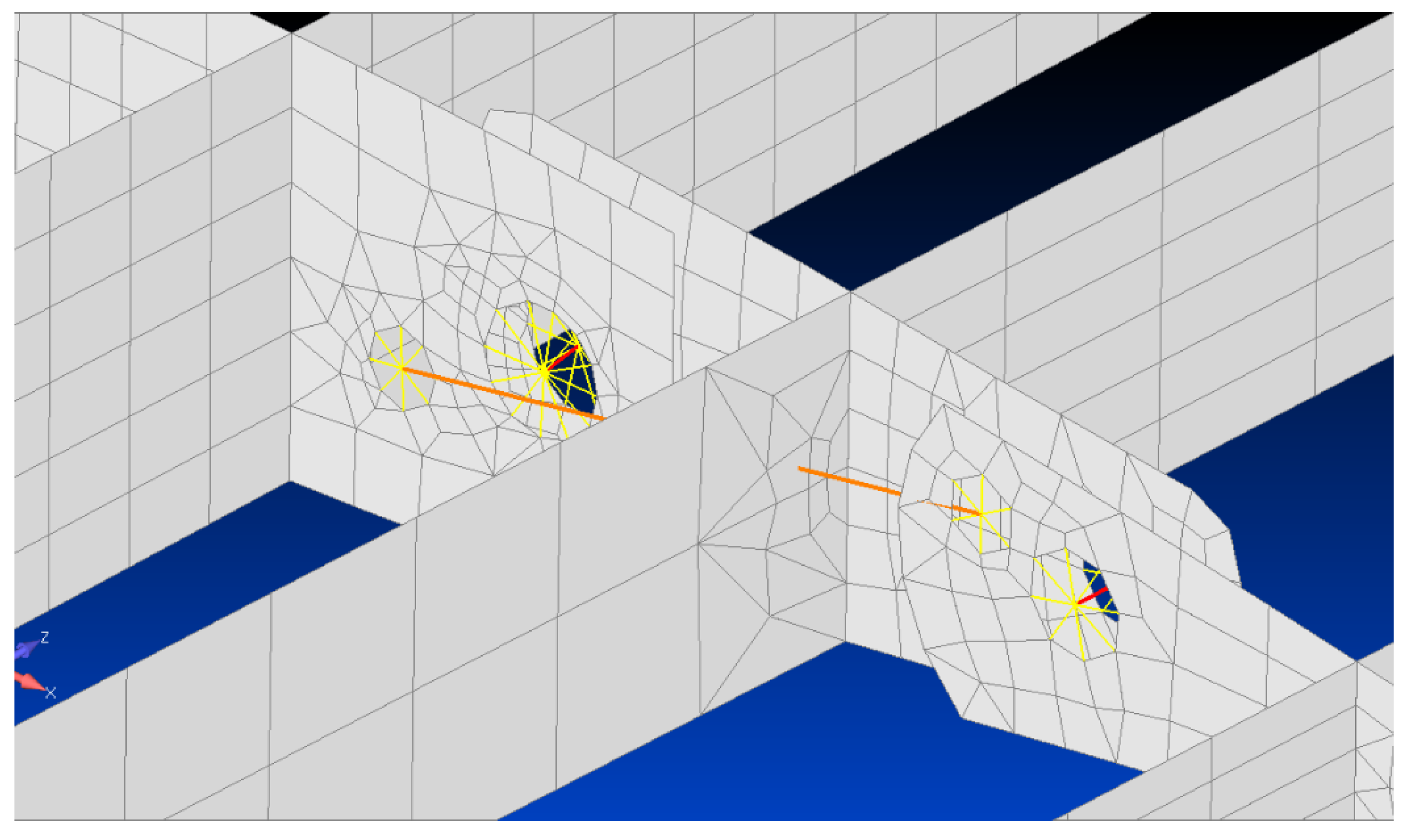
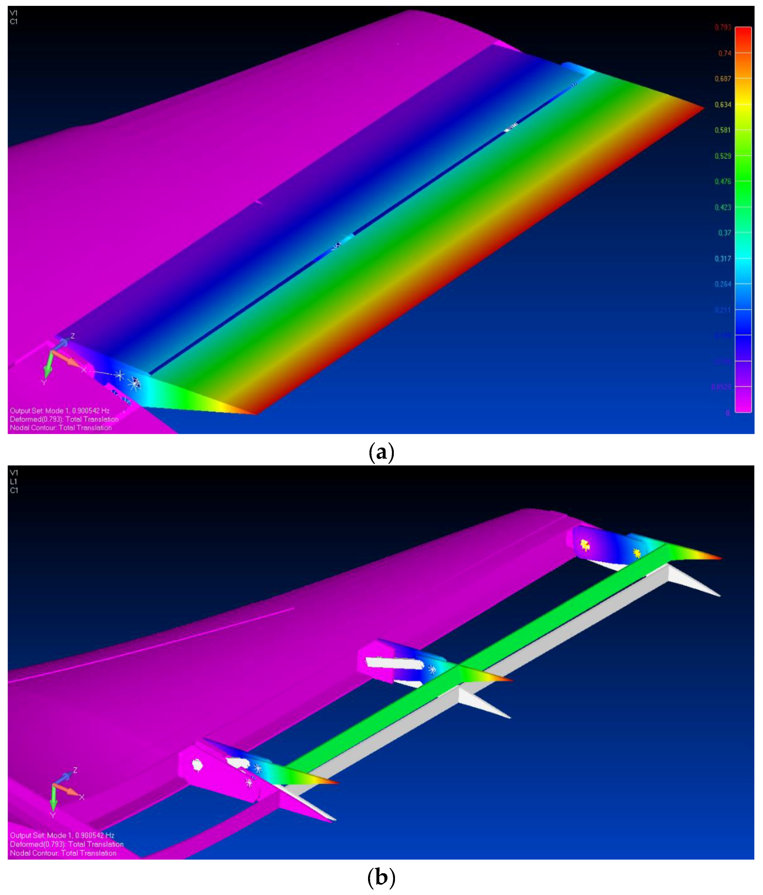
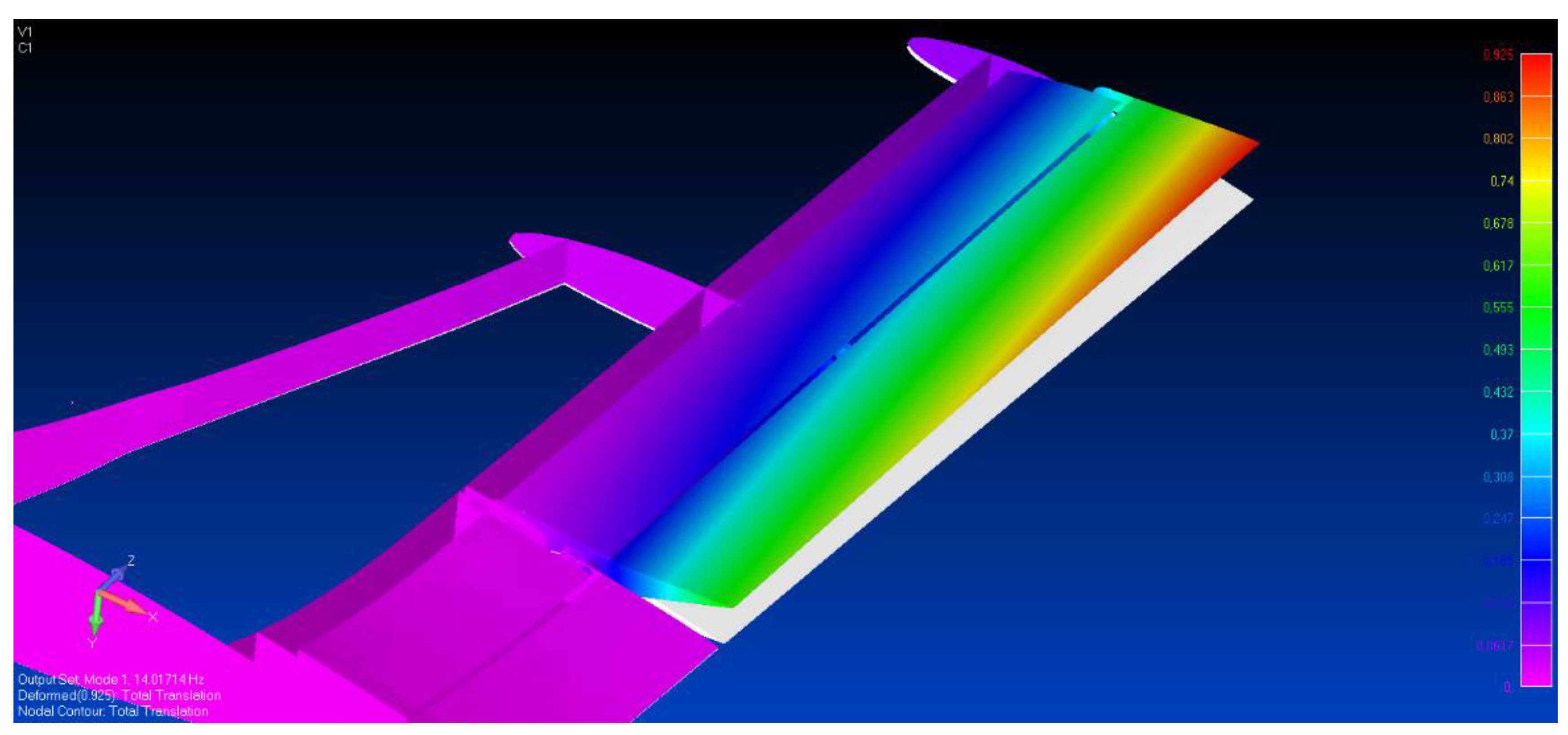
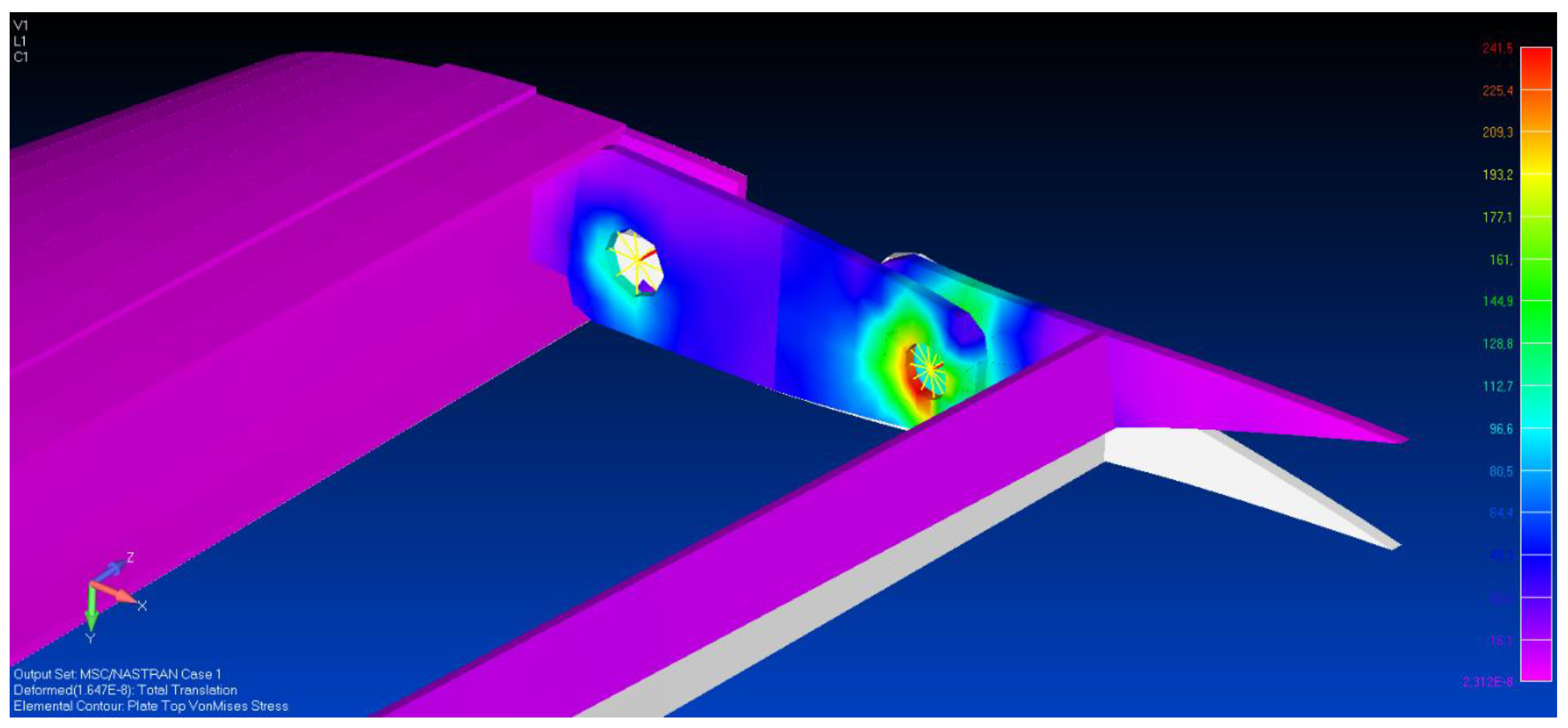
4. Actuators and Kinematics Integration into the FE Model

In order to simulate the actuator stiffness (on the order of 5 kN/mm) and actuation chain into the morphing winglet model, an equivalent torsional spring was added to both the upper- and lower-morphing tabs, respectively. In such a more realistic condition, the natural frequency of the mechanical system, referred to as morphing mode of the device in operative conditions, increased up to 14 Hz, being totally dependent on the actuation kinematics. Figure 13 shows the morphing mode reached by the upper tab while considering the actuation system stiffness. In this case, the actuator constrained the lower-morphing rib through its nominal stiffness, and hence, the entire tab through the structural box. It is worth noting that due to the morphing tab elasticity, the upper region of the tab deflected more than the lower one since the actuator was mechanically attached to the lower region of the upper tab. This impacted the actual morphing aeroshape and deserves special attention in the aerodynamic design to properly estimate the performance degradation due to the structural elasticity. Alternatively, this effect may be compensated through an adequate structural compliance distribution. Due to the higher span-wise stiffness of the lower morphing tab as a consequence of its reduced dimensions, the structural response, not addressed in this work, was much more uniform.
The final step of the preliminary assessment of the electromechanical actuator integration into the morphing structure consisted in evaluating the static response of the morphing tabs under operative loads. The morphing ribs and spar were made of an aluminum alloy, whereas the static aerodynamic loads were deduced from the literature [26]. Such aerodynamic forces, resulting in a hinge moment on the order of 101.7 Nm, were simulated by applying aerodynamic pressure to the tabs upper skin. These simulations predicted a maximal stress of about 240 MPa, which was lower than the yield strength (500 MPa for Al 7075-T6). An example of stress distribution over the finger-like mechanism is shown in Figure 14. The global added bending stiffness due to the partitioned skin was assumed negligible with respect to the global structure, even if it contributed to reduce the relative displacements between the ribs under the action of the aerodynamic pressure.

5. Conclusions

Next-generation aircraft will incorporate new fault-tolerant electromechanical actuators and innovative structural concepts to increasingly interact with the environment and adapt its functions to changing flight conditions. In this paper, an adaptive winglet device combining two independent electro-mechanical actuation and hinge-connected mechanisms were investigated to demonstrate the feasibility of an adaptive wing load control system including electrical actuators for reducing system complexity. Such a concept appears acceptable in less safety-critical aircraft devices, although there is a lack of advanced knowledge and experience regarding the reliability and the potential risks associated with actuator failures.
A major potential advantage is the possibility to activate the individual winglet tabs either synchronously or independently to different angles with a certain redundancy. Lift over Drag enhancements are adaptively achieved in climb and descent conditions where regional aircraft typically spend a significant segment of the flight time. On thestructural side, the wing bending and torsion are controlled by acting on both surfaces through tailored upward/downward deflections. Additionally, aircraft lateral control is enhanced in the case of an engine failure, and critical conditions such as EMA jamming are dramatically mitigated by the surface redundancy.
In order to check the validity of the proposed architecture, the authors investigated some important aspects related to the preliminary design of such an adaptive system. Focus was given to the actual integration of the actuators to assess the structural response of the device both in free play and nominal conditions. In the former study, particularly useful in the early design stages of a morphing component, the hinges and links were assumed rigid. The results characterized morphing system capabilities without incurring the computational expense associated with a full aeroelastic analysis. It is not surprising that the elasticity of the hinges did not affect the low-frequency morphing mode of the device, occurring at 0.9 Hz. After that, these rigid elements were replaced by lumped springs and the stiffness of the actuation chain was simulated by a torsional spring between the first two adjacent blocks of the finger-like mechanism. The actuation elasticity significantly affected the morphing mode of the device, increasing up to 14 Hz, and its structural dynamic response, by highlighting potential consequences on aeroelastic stability margins. The resulting gap, mainly due to the actuator stiffness with respect to the fully rigid predictions, suggested to optimize either the structural compliance or the actuation distribution. It follows that ensuring adequate structural flexibility remains an ongoing and important problem for morphing system kinematics. The structural stability was also investigated by ensuring the structure deformed to a stable configuration under the action of aerodynamic forces. Further studies are planned to assess the behavior of the structure by taking into account the contribution of the transmission chains to the overall stiffness of the morphing device. Because of the importance of aeroelastic phenomena in the design of aircraft aerodynamic surfaces, further development will focus on aeroelastic stability margins and safety related implications of actuators failures. To ensure the required performance and minimize consumed energy for a given closed-loop performance, the EMA controller will be matured by optimizing the conventional cascade loop parameters (position/speed/current). A non-linear controller including compensation of friction in the mechanical transmission, variation of supply voltage, temperature effects, and feed-forward for reduction of positioning dynamic error will also be implemented to boost the actuator dynamics and accuracy. Detailed experimental tests will be finally implemented.

Author Contributions

Conceptualization, I.D.; methodology, I.D., F.G., and M.P.; software, I.D. and M.P.; validation, I.D. and F.G.; formal analysis, I.D.; investigation, M.P.; resources, G.P.; data curation, I.D.; writing—original draft preparation, I.D., F.G. and M.P.; writing—review and editing, I.D.; visualization, M.P.; supervision, I.D.; project administration, G.P.; funding acquisition, I.D. and G.P.

Funding

The project leading to these results has received funding from the Clean Sky 2 Joint Undertaking under the European Union’s Horizon 2020 research and innovation programme under Grant Agreement no. 807089 - REG GAM 2018 (Amdt. Ref. No AMD-807089-10).

Acknowledgments

The authors wish to acknowledge the Clean Sky 2 Airgreen 2 project partners involved in the design and development of the adaptive winglet device.

Conflicts of Interest

The authors declare no conflict of interest.

References

  1. Concilio, A.; Dimino, I.; Lecce, L.; Pecora, R. Morphing Wings Technology for Large Commercial Aircraft and Helicopter Scenario; Butterworth-Heinemann: Oxford, UK, 2017; 978p, ISBN 978-0-08-100964-2. [Google Scholar] [CrossRef]
  2. Woelcken, P.C.; Papadopoulos, M. Smart Intelligent Aircraft Structures (SARISTU); Springer International Publishing: Cham, Switzerland, 2016; ISBN 978-3-319-22413-8. [Google Scholar]
  3. Barbarino, S.; Bilgen, O.; Ajaj, R.M.; Friswell, M.I.; Inman, D.J. A Review of Morphing Aircraft. J. Intell. Mater. Syst. Struct. 2011, 22, 823–877. [Google Scholar] [CrossRef]
  4. Bishay, P.L.; Burg, E.; Akinwunmi, A.; Phan, R.; Sepulveda, K. Development of a new span-morphing wing core design. Designs 2019, 3, 12. [Google Scholar] [CrossRef]
  5. Fichera, S.; Isnardi, I.; Mottershead, J.E. High-Bandwidth Morphing Actuator for Aeroelastic Model Control. Aerospace 2019, 6, 13. [Google Scholar] [CrossRef]
  6. Mills, J.; Ajaj, R. Flight Dynamics and Control Using Folding Wingtips: An Experimental Study. Aerospace 2017, 4, 19. [Google Scholar] [CrossRef]
  7. Bendsøe, M.P.; Sigmund, O. Topology Optimization—Theory, Methods, and Applications; Springer: Heidelberg/Berlin, Germany, 2003. [Google Scholar]
  8. Amendola, G.; Dimino, I.; Concilio, A.; Andreutti, G.; Pecora, R.; Lo Cascio, M. Preliminary design process for an adaptive winglet. Int. J. Mech. Eng. Robot. Res. 2018, 7, 83–92. [Google Scholar] [CrossRef]
  9. Pecora, R.; Amoroso, F.; Magnifico, M.; Dimino, I.; Concilio, A. KRISTINA: Kinematic rib-based structural system for innovative adaptive trailing edge. In Proceedings of the SPIE—The International Society for Optical Engineering, Las Vegas, NV, USA, 20–24 March 2016. [Google Scholar]
  10. Zhao, A.; Zou, H.; Jin, H.; Wen, D. Structural design and verification of an innovative whole adaptive variable camber wing. Aerosp. Sci. Technol. 2019, 89, 11–18. [Google Scholar] [CrossRef]
  11. Aage, N.; Andreassen, E.; Lazarov, B.S.; Sigmund, O. Giga-voxel computational morphogenesis for structural design. Nature 2017, 550, 84–86. [Google Scholar] [CrossRef] [Green Version]
  12. Arena, M.; Nagel, C.; Pecora, R.; Schorsch, O.; Concilio, A.; Dimino, I. Static and Dynamic Performance of a Morphing Trailing Edge Concept with High-Damping Elastomeric Skin. Aerospace 2019, 6, 22. [Google Scholar] [CrossRef]
  13. Dimino, I.; Concilio, A.; Pecora, R. Safety and Reliability Aspects of an Adaptive Trailing Edge Device (ATED). In Proceedings of the 24th AIAA/AHS Adaptive Structures Conference, San Diego, CA, USA, 4–8 January 2016. [Google Scholar]
  14. Amendola, G.; Dimino, I.; Magnifico, M.; Pecora, R. Distributed Actuation Concepts for a Morphing Aileron device. Aeronaut. J. 2016, 120, 1365–1385. [Google Scholar] [CrossRef]
  15. Amendola, G.; Dimino, I.; Amoroso, F.; Pecora, R. Experimental characterization of an Adaptive Aileron: Lab tests and FE correlation. In Sensors and Smart Structures Technologies for Civil, Mechanical, and Aerospace Systems; SPIE Smart Structures/NDE: Las Vegas, NV, USA, 2016; Volume 9803, 98034p. [Google Scholar] [CrossRef]
  16. Della Vecchia, P.; Corcione, S.; Pecora, R.; Nicolosi, F.; Dimino, I.; Concilio, A. Design and integration sensitivity of a morphing trailing edge on a reference airfoil: The effect on high-altitude long-endurance aircraft performance. J. Intell. Mater. Syst. Struct. 2017, 28, 2933–2946. [Google Scholar] [CrossRef] [Green Version]
  17. Dimino, I.; Diodati, G.; Concilio, A.; Volovick, A.; Zivan, L. Distributed electromechanical actuation system design for a morphing trailing edge wing. In Industrial and Commercial Applications of Smart Structures Technologies; SPIE Smart Structures/NDE: Las Vegas, NV, USA, 2016; Volume 9801, p. 980108. [Google Scholar] [CrossRef]
  18. Dimino, I.; Flauto, D.; Diodati, G.; Concilio, A.; Pecora, R. Actuation System Design for a Morphing Wing Trailing Edge. Recent Pat. Mech. Eng. 2014, 7, 138–148. [Google Scholar] [CrossRef]
  19. Diodati, G.; Concilio, A.; Ricci, S.; De Gaspari, A.; Huvelin, F.; Dumont, A.; Godard, J.-L. Estimated Performances of an Adaptive Trailing Edge Device Aimed at Reducing Fuel Consumption on a Medium-Size Aircraft. In Proceedings of the SPIE 20th Annual Symposium on Smart Structures and Materials, San Diego, CA, USA, 10–14 March 2013. [Google Scholar]
  20. Pecora, R.; Dimino, I. SMA for Aeronautics. In Shape Memory Alloy Engineering for Aerospace, Structural and Biomedical Applications; Butterworth-Heinemann: Oxford, UK, 2015; pp. 275–304. [Google Scholar] [CrossRef]
  21. Bishay, P.L.; Finden, R.; Recinos, S.; Alas, C.; Lopez, E.; Aslanpour, D.; Flores, D.; Gonzalez, E. Development of an SMA-based camber morphing UAV tail core design. In Smart Materials and Structures; IOP Publishing: Bristol, UK, 2019. [Google Scholar] [CrossRef]
  22. Systems. Available online: https://www.cleansky.eu/systems (accessed on 5 May 2019).
  23. Gavrilovic, N.; Rasuo, B.; Dulikravich, G.; Parezanovic, V. Commercial Aircraft Performance Improvement Using Winglets. FME Trans. 2015, 43, 1–8. [Google Scholar] [CrossRef]
  24. Allen, J.B. Articulating Winglets. US patent 5,988,563 A, 23 November 1999. [Google Scholar]
  25. Irving, J.; Davies, R. Wing Tip Device. US patent 7,275,722 B2, 2 October 2007. [Google Scholar]
  26. Wildschek, A.; Storm, S.; Herring, M.; Drezga, D.; Korian, V.; Roock, O. Design, Optimization, Testing, Verification, and Validation of the Wingtip Active Trailing Edge. In Smart Intelligent Aircraft Structures (SARISTU); Springer: Cham, Switzerland, 2016; pp. 219–255. [Google Scholar]
  27. Amendola, G.; Dimino, I.; Concilio, A.; Magnifico, M.; Pecora, R. Numerical design of an adaptive aileron. In Proceedings of SPIE—The International Society for Optical Engineering; SPIE: Las Vegas, NV, USA, 2016; Volume 9803, p. 98032A. ISBN 9781510600447. [Google Scholar] [CrossRef]
  28. Amendola, G.; Dimino, I.; Concilio, A.; Amoroso, F.; Pecora, R. Preliminary design of an adaptive aileron for the next generation regional aircraft. J. Theor. Appl. Mech. 2017, 55, 307–316. [Google Scholar] [CrossRef]
  29. Abraham, T. Magnets and magnetic materials: A technical economic analysis. J. Miner. Met. Mater. Soc. 1995, 47, 16–18. [Google Scholar] [CrossRef]
  30. Kouvel, J.S. Intermetallic Compounds; Westbrook, J.H., Ed.; Wiley: New Jersey, NJ, USA, 1967; pp. 529–568. [Google Scholar]
  31. Stadelmaier, H.H.; Reinsch, B. Intermetallic Compounds—Magnetic, Electrical and Optical Properties and Applications of Intermetallic Compounds; Westbrook, J.H., Fleischer, R.L., Eds.; John Wiley & Sons: Hoboken, NJ, USA, 2000; pp. 31–50. [Google Scholar]
  32. Sundar, R.S.; Deevi, S.C. Soft Magnetic FeCo Alloys: Alloy Development, Processing, and Properties. Int. Mater. Rev. 2005, 50, 157–192. [Google Scholar] [CrossRef]
  33. Zetterstrom, S. Electromechanical steering, suspension, drive and brake modules. In Proceedings of the IEEE 56th Vehicular Technology Conference, Vancouver, BC, Canada, 24–28 September 2002; Volume 3, pp. 1856–1863. [Google Scholar]
  34. Maron, C.; Dieckmann, T.; Hauck, S.; Prinzler, H. Electromechanical Brake System: Actuator Control Development System; SAE Technical Paper; SAE International: Michigan, MI, USA, 1997. [Google Scholar]
  35. Schwarz, R.; Isermann, R.; Böhm, J.; Nell, J.; Rieth, P. Modeling and Control of an Electromechanical Disk Brake; SAE Technical Paper 980600; SAE International: Michigan, MI, USA, 1998. [Google Scholar]
Figure 1. Morphing winglet concept with upper and lower control surfaces.
Actuators 08 00042 g001
Figure 2. Finger-like mechanism of the morphing winglet trailing edge.
Actuators 08 00042 g002
Figure 3. Segmented skin of the morphing winglet trailing edge.
Actuators 08 00042 g003
Figure 4. Hinges and pin modelling scheme of the reference finger-like morphing concept.
Actuators 08 00042 g004
Figure 5. Free play floating mode of the upper morphing tab (frequency = 0.9 Hz). (a) Morphing aeroshape mechanism; (b) Detail of the undeformed and deformed ribs.
Actuators 08 00042 g005
Figure 6. Non-concentric shaft layout of the actuators.
Actuators 08 00042 g006
Figure 7. Electromechanical actuator for morphing winglet application.
Actuators 08 00042 g007
Figure 8. Direct-drive configuration with magnets permanently bonded directly onto the ball-nut.
Actuators 08 00042 g008
Figure 9. Winglet torque comparison between FeCo and FeSi stators.
Actuators 08 00042 g009
Figure 10. Electromagnetic power-off brake with clutch disk.
Actuators 08 00042 g010
Figure 11. Comparison between numerical and experimental results about solenoid forces.
Actuators 08 00042 g011
Figure 12. Comparison between theoretical, experimental, and recomputed braking torque.
Actuators 08 00042 g012
Figure 13. Morphing mode of the upper-morphing tab in operative condition (frequency = 14 Hz).
Actuators 08 00042 g013
Figure 14. Stress distribution (MPa) over the finger-like mechanism under aerodynamic loads.
Actuators 08 00042 g014
Table 1. Actuators’ performance requirements.
ParameterValue
Maximum operating axial load3500 N
Maximum static axial load5000 N
Total operating stroke10 mm for the lower surface
20 mm for the upper surface
Max speed5 mm/s
Table 2. Comparison between standard direct-drive electromechanical actuator (EMA) and winglet direct-drive architecture.
FeatureStandard Direct-Drive ConfigurationWinglet Direct-Drive Configuration% Increase
Power-to-weight ratio in discontinuous operation point175 W/kg205 W/kg17%
Power-to-volume ratio in discontinuous operation point 925 W/L1700 W/L84%

