Article

Electric-Pneumatic Actuator: A New Muscle for Locomotion

1
Lauflabor Locomotion Laboratory, Institute of Sport Science, Centre for Cognitive Science, TU Darmstadt, 64289 Darmstadt, Germany
2
ECE Department, School of Engineering, University of Tehran, Tehran 1439957131, Iran
3
Graduate School of Engineering Science, Osaka University, 1-3 Machikaneyama-cho, Toyonaka, Osaka 560-8531, Japan
*
Author to whom correspondence should be addressed.
Actuators 2017, 6(4), 30; https://doi.org/10.3390/act6040030
Submission received: 19 June 2017 / Revised: 8 September 2017 / Accepted: 16 October 2017 / Published: 25 October 2017
(This article belongs to the Special Issue Variable Stiffness and Variable Impedance Actuators)

Abstract

:
A better understanding of how actuator design supports locomotor function may help develop novel and more functional powered assistive devices or robotic legged systems. Legged robots comprise passive parts (e.g., segments, joints and connections) which are moved in a coordinated manner by actuators. In this study, we propose a novel concept of a hybrid electric-pneumatic actuator (EPA) as an enhanced variable impedance actuator (VIA). EPA is consisted of a pneumatic artificial muscle (PAM) and an electric motor (EM). In contrast to other VIAs, the pneumatic artificial muscle (PAM) within the EPA provides not only adaptable compliance, but also an additional powerful actuator with muscle-like properties, which can be arranged in different combinations (e.g., in series or parallel) to the EM. The novel hybrid actuator shares the advantages of both integrated actuator types combining precise control of EM with compliant energy storage of PAM, which are required for efficient and adjustable locomotion. Experimental and simulation results based on the new dynamic model of PAM support the hypothesis that combination of the two actuators can improve efficiency (energy and peak power) and performance, while does not increase control complexity and weight, considerably. Finally, the experiments on EPA adapted bipedal robot (knee joint of the BioBiped3 robot) show improved efficiency of the actuator at different frequencies.

1. Introduction

In the biological body, different muscles have similar general functionality but vary in contraction properties (e.g., maximum contraction speed and maximum isometric force). In robotics, we may replicate this by different actuator types (e.g., electric motors, and pneumatic and hydraulic actuators). Electric motors (EM) are widely utilized in legged robots (e.g., Asimo [1] and HRP-4 [2]). These actuators are able to achieve the precise position or torque control. Because of their high torque-velocity range, high performance in continuous operation with constant speeds and precision in position (torque) control, they are suitable for manipulation (e.g., in industrial robots). However, in a hybrid task of legged locomotion suffering from impacts, requiring efficient actuation in a wide range of torque/velocity and having close interaction with uncertain environment, EMs loose part of their fortes. In addition, steady gaits as rhythmic movements, comprise combinations of periodic motions. Therefore, employing compliant actuators that can easily change their natural frequency in legged robots facilitate locomotion.
Serial elastic actuators (SEAs, [3]) provide the first requirement of artificial legged locomotory systems by adding flexibility to EMs [4,5,6]. Furthermore, compared to a direct drive (rigid) EM, the SEA has lower impedance, higher impact resistance and higher energy efficiency [7,8,9]. These advantages are achieved by storing and returning elastic energy during the loading/unloading cycle (mimicking the stretch-shortening cycles in human muscles, [10]). Nevertheless, this is not sufficient for adapting to different gait conditions (e.g., speed) while keeping performance, efficiency and robustness against uncertainties and perturbations. In contrast to SEAs, human muscles can adapt compliance to cope with challenges such as changing ground conditions (e.g., damping, stiffness [11], rough terrains [12], recovering from perturbations [13]) and changing the motion speed [14].
To overcome this limitation of SEAs, stiffness adjustment was introduced in variable impedance actuators (VIA) [15]. VIAs are usually constructed by adding another EM (e.g., a direct drive servo motor) to the actuator design to control spring stiffness (e.g., via changing the lever arm or preloading of the spring) [16]. It improves the controllability of the output which is useful for enabling legged robots to cope with changing ground conditions and changing the motion speed efficiently. However, the controller and the mechanical design are necessarily much more complex [15,16] than EM and SEA. Furthermore, in such designs, the second actuator of VIA usually has low power and low bandwidth in order to permit spring stiffness adjustment. Hence, the second actuator of VIA is not designed to be employed as a power generator. In addition, both EMs continuously consume power during all movements when they are back-drivable (e.g., as in the humanoid robot Veronica [16]), and hence are not energy efficient. Therefore, VIAs can reduce the required power, but not the torque [8,17]. We need an actuator which can overcome these disadvantages of VIAs.
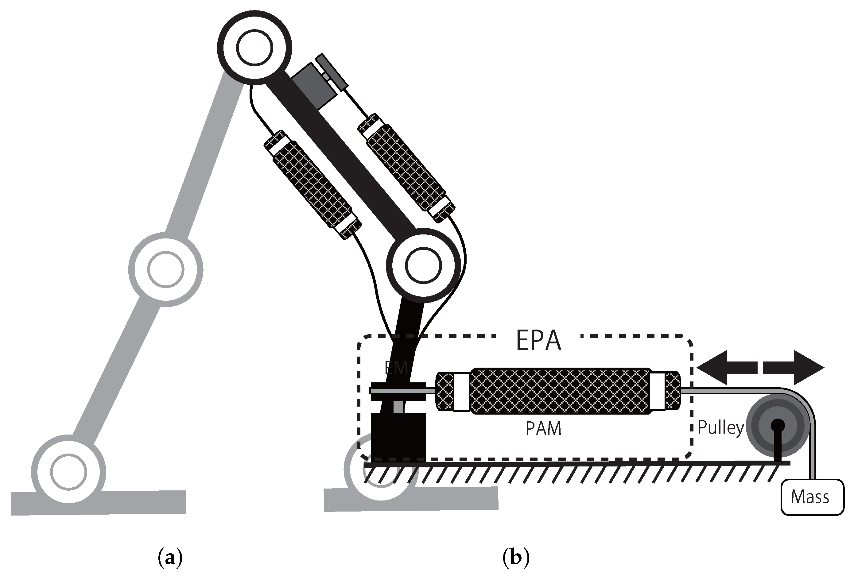
Our solution is a new hybrid Electric-Pneumatic Actuator (EPA) which combines pneumatic artificial muscles (PAM) with electric motors (EM) (e.g., as shown in Figure 1a). In contrast to EMs, pneumatic actuators are well-suited to mimic compliant behavior, but they fail in accurate control (e.g., position control) [18,19]. PAMs are similar to biological muscles [20] having nonlinear force-length relationship. Hence, PAMs can be considered as the adjustable stiffness (like a preloaded spring [15]) beside EM to develop a new variable impedance actuator. Compared to EMs, PAMs are compliant, cheap and lightweight, but they have low bandwidth. As both EM and PAM individually cannot well replicate biological actuation, we propose combining them to better match the requirements for legged locomotion. In EPA, the PAM can be used: (i) as a fixed adjustable compliance; (ii) for energy management as a separate actuator to inject or absorb energy; and (iii) a passive nonlinear spring with muscle-like force-length relationship. It is noticeable that based on the actuators’ properties and with inspiration from human motor control, we can avoid increasing control complexity which might be expected from combining two different actuators.
In the first case, changing the stiffness can be used for two targets: (1) presetting of the actuator impedance for a fixed periodic motion with a determined gait characteristic (e.g., frequency); and (2) adapting the compliance during each step. For the first target, required energy in PAMs are ignorable. For the second target, an optimal solution can be found to compromise between energy expenditure in PAM and EM to minimize the total energy. In this paper, we show the advantages of the EPA regarding the first target both in the simulations and experiments. When we close the valves energy consumption in the PAM is minor. Thus, with a pressurized air tank, we just need to open and close the valves once for each frequency. Suppose that the actuator is used for steady walking (e.g., at regular speed). We only need to set the pressure of each muscle to a predefined value which is optimal for the periodic motion at that frequency. Hence, for steady state movement at a certain frequency the required energy to switch the valves is ignorable compared to the total energy required during that gait (e.g., 10 min walking).
To develop the new actuator, first we need a precise dynamic model of PAMs and EMs. Electric motors have well-accepted precise models, while PAMs are not well studied in the literature. In this paper, we examined two different static and dynamic models and presented a new model to identify our PAM dynamic behavior to be employed in EPA. An experimental setup was built to provide data for developing a dynamic model of EPA. Then, simulation studies were performed to verify the capabilities of the new actuator in producing periodic movement, required for legged locomotion. Finally, we tested how PAM compliance adjustment (by setting the air pressure) can reduce energy consumption in periodic movement required in legged locomotion. This last experiment was performed in a knee joint of a bioinspired bipedal robot (BioBiped3 [21]).

2. Electric-Pneumatic Actuator

In this section, we present the concept, model and implementation of the EPA, the hybrid Electric-Pneumatic Actuator. As mentioned in Section 1, the goal of combining the two actuators is to benefit from the advantages of both actuators without increasing control complexity and probable side effects, as much as possible. Therefore, we take the following steps: (i) developing a hardware setup and doing identification experiments; (ii) developing a model of EPA based on hardware experiments; (iii) simulation analysis using the model developed in Step ii; and (iv) doing some preliminary hardware experiments with BioBiped3 robot as a proof of concept. For simplifying control of periodic movements in locomotion, we divide motion control into two sub-tasks performing the periodic movement (position control) and tuning the natural frequency (with impedance control). This task distribution is a base for determining the role of EM and PAM in our actuation mechanism both in simulations and hardware experiments. Therefore, the PAM is mainly used for impedance (stiffness) adjustment while the EM is employed for position control. With this hybrid control, we can do both position, impedance, and consequently, force control in a simple way.

2.1. PAM Identification Setup

EPA is composed of electric motor (EM) and pneumatic air muscle (PAM). Since there is a well accepted model of the EM, here we focus on the PAM. A pneumatic artificial muscle is a membrane that expands radially and contracts axially when inflated. Accordingly, it can generate high pulling forces along the longitudinal axis [22]. In this paper, we employ Mckibben type pneumatic artificial actuator which can control mechanical compliance by tuning air pressure. If the optimal pressure is supplied in advance, closed valves do not require energy during movement. In addition, if the robot is equipped with a filled air tank, there will be no energy loss during conducting task, except air leakage which is minor if the time and speed of the gait are moderate (e.g., walking at normal speed for 10 min).
In contrast to EM, there is no comprehensive dynamic model of PAM predicting relation between the muscle force, position and pressure [20,23,24,25,26,27,28]. Chou et al. [23] proposed an experiment-based static model containing only position and pressure term which is not suitable for a dynamic motion. To overcome the limitations of the static model, few dynamic models were introduced which are usually represent the best the studied setup. For example, Tang et al. [26] proposed a dynamic model extending the static one by adding viscous damping and coulomb friction. Such models are reasonably fitted to their experimental setup, but applying it to our different setup is not preferred. To derive a precise model of EPA, we have developed our experimental setup including an EM in series with a PAM. First, we introduce a new dynamic model of PAM and then combine it with the model of EM to generate the EPA model. The goal is not developing a new general model for PAM, but a more precise simulation model of our EPA setup.
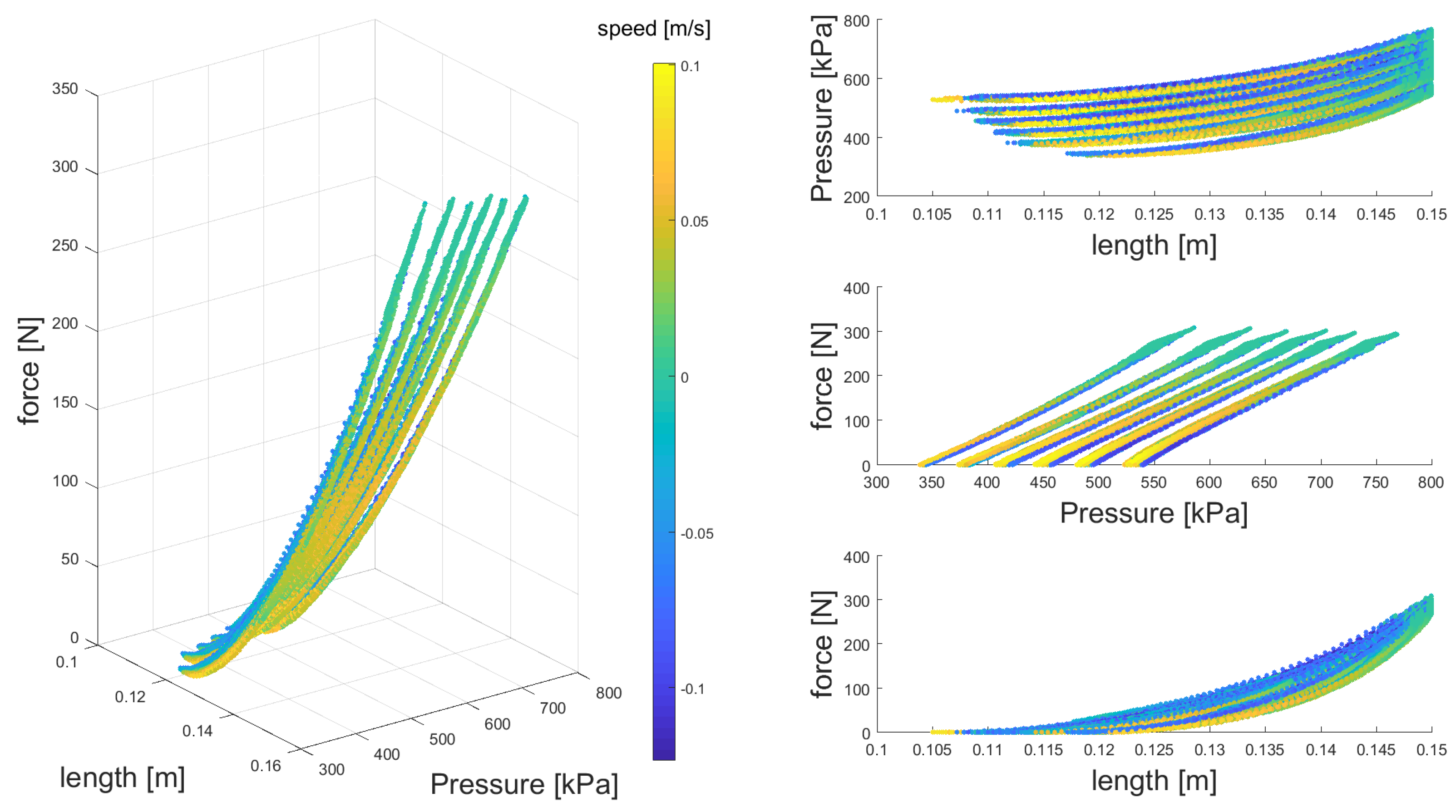
Our experimental setup to identify the PAM dynamic model included a brushless DC motor (120 W; Maxon, Sachseln, Switzerland), a force sensor (ALM-170; AMOS, Mannheim, Germany), and a self-made PAM connected by very stiff bylon straps (called non-stretchable nylon straps [29]). We measured muscle force, displacement and pressure in a periodic movement with different magnitudes and frequencies. The PAM elongation was computed by the motor joint angle. The pressure inside the PAM was measured by an air pressure sensor (PSE 530; SMC, Tokyo, Japan). A set of Beckhoff EtherCAT terminals (EK1100, EL2124, EL3004, EL4034, and EL9011; Beckhoff, Verl, Germany) were used for controlling the motor and collecting data. A Matlab (MathWorks, Natick, MA, USA) xPC Target machine programmed by Matlab 2015b Simulink was used for the real time control of the setup.
The PAM was inflated with a certain amount of air in no load condition before each experiment. These initial pressure values were distributed uniformly between 460 kPa and 640 kPa (every 30 kPa). During each experiment, the motor speed was controlled with a randomized profile for 200 s. Except the motor encoder data, collected with a sampling rate of 500 Hz, all other sensors’ sampling rate were 1000 Hz. After data normalization, nonlinear regression analysis and curve fitting are employed to identify the PAM dynamic model.

2.2. Dynamic Model of PAM

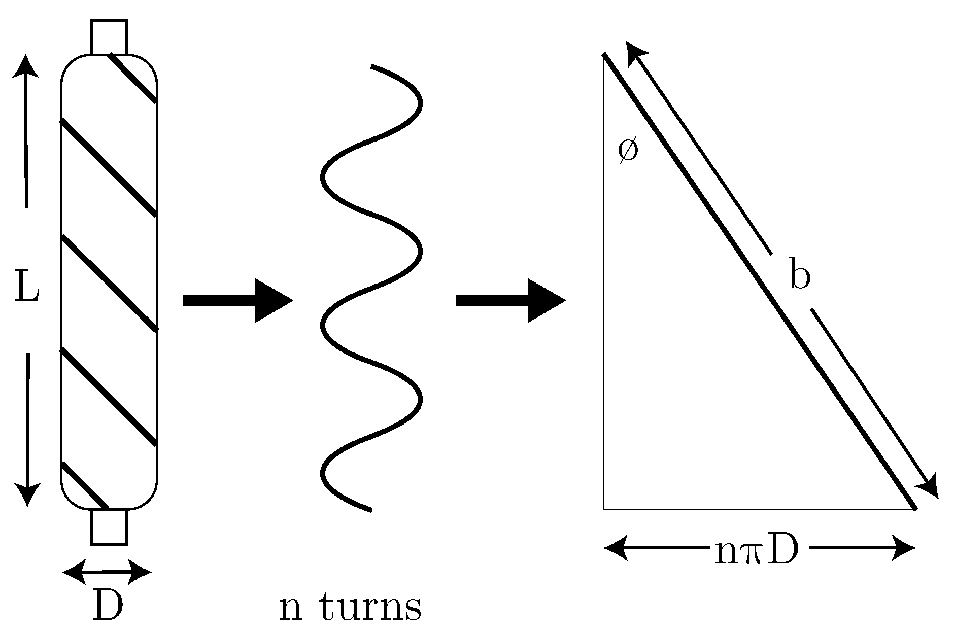
The simplest and most common model of PAM is the static one which uses the PAM length L and pressure P, to estimate the muscle force F S t .
F S t = P b 2 4 π n 2 ( 3 b 2 L 2 1 )
in which b and n are the thread length and the number of turns for a single thread, respectively, as shown in Figure 2. With a fixed thread length, the volume of the air muscle (V) is calculated based on the muscle length as follows.
V = ( b 2 L 2 ) L 4 π n 2
With a fixed amount of the air mass, changing the muscle length (from L 0 to L 1 ) results in a different pressure ( P 1 ) from the initial one ( P 0 ). This can be calculated by the Boyle’s law:
P 1 = P 0 V 0 V 1 = P 0 ( b 2 L 0 2 ) L 0 ( b 2 L 1 2 ) L 1
Therefore, if the air mass is fixed, and the muscle length is changing, e.g., with an electric motor (see Section 2.1) a unique relationship between the muscle force, pressure and length can be found using Equations (1) to (3). In this model, the effect of length changing speed ( L ˙ ) is not considered.
In [26], a dynamic model presented including the static model, viscous damping and coulomb friction.
F T a n g = F S t F D a F C o
in which, Coulomb friction F C o is velocity-irrelevant and viscous damping F D a is dependent on velocity. Here, F D a and F C o are calculated by the following equations
F S t T a n g = P ( K 2 x 2 + K 1 x + K 0 ) + S 2 x 2 + S 1 x + S 0
F D a = D 2 P x ˙ 2 + D 1 P x ˙
F C o = ( P φ ) ( N 2 x 2 + N 1 x + N 0 ) s i g n ( x ˙ )
where K i , S i , D i and N i (for i = 0 , 1 , 2 ) are the coefficients to be determined and the x = L 0 L is contraction length. In addition, φ is introduced as a correction term which is empirically approximated by m as the constant hanging mass (see [26] for details).
In this model, static part is different from the first model and different combinations of pressure, length and speed with various powers are multiplied to each other. This model might be overtuned to the specific experiments presented in [26]. Inspired by this model, we have defined a new model. In our dynamic model, we employed a 3D order polynomial to approximate the PAM force as a function of muscle pressure, length and speed. First, we consider all possible multiplication of inputs (all terms of the 3D order polynomial) which will be 64 elements. Then, the smallest coefficient was removed and the approximation error is evaluated. If the error is below a threshold, this reduction procedure is repeated. This algorithm results in the following formulation for approximating muscle force.
F = C 1 L P + C 2 L ˙ P + C 3 L ˙ 2 + C 4 L ˙ P 2 + C 5 .
in which C 1 to C 5 are the constant coefficients. Here, we found that all terms in the dynamic model of Tang et al. is not required, while two additional terms ( C 3 L ˙ 2 and C 4 L ˙ P 2 ) are added. These two terms show a pressure dependent nonlinear damping behavior of the muscle. This could result in the hysteresis observed in actuation with PAMs.
Our model comprises the dynamic Equation (8) besides Equations (2) and (3). We compared this model with the two aforementioned ones to find the most precise approximation to develop EPA model. The static model was selected because it is the most common model in the literature. The dynamic model of Tang et al. was chosen for its acceptable description of the physical phenomenon in PAM by employing viscous damping and coulomb friction terms. To evaluate the correlation between the model and the experimental results, the R 2 coefficient was utilized. The results show that our method gives better approximation (higher R 2 correlation) compared to the other two methods.

2.3. EPA Evaluation

Locomotion can be developed by a combination of oscillatory movements for different locomotor sub-functions. For any active oscillating mechanism (e.g., actuated spring-mass system), there exists a natural frequency, which needs the minimum effort to move. As mentioned before, our control strategy is splitting control of the oscillatory movement to position control by EM and tuning the natural frequency by the PAM. We test this idea in simulations and hardware experiments. The focus of the simulation study is on serial configuration while in the hardware experiment, the emphasis is on benefits of the parallel PAM.

2.3.1. Simulation Study

Considering an SEA controlled robot joint, it is shown that for a periodic movement (e.g., mimicking bouncing in locomotion), one optimal stiffness exists for each frequency. By adjusting the spring stiffness to this optimal value, the actuator can move the system states from any initial condition to the desired limit cycle and just compensate losses afterward. In the ideal case (without losses), the motor may rest after reaching the limit cycle. With SEA it is not possible to change the stiffness. However, in EPA, PAM air pressure can be used to adjust the actuator stiffness and consequently the impedance. Using the new model of PAM, we developed an EPA simulation model with serial configuration and showed how fine-tuning of PAM results in an efficient control by EM. For example, in a bouncing gait, the optimal muscle stiffness for different hopping conditions (e.g., frequency) can be identified with this approach. Note that the additional energy for adjusting the PAM (compared to SEA) is required just once for each hopping condition and, after reaching the limit cycle, PAM does not spend any extra energy with closing the valves. Still, the control complexity of the EPA is similar to that of an SEA.
The serial EPA (PAM in series with EM) model is simulated in MATLAB using the proposed dynamic model of the PAM. In this study, we investigate how this arrangement can increase efficiency of the periodic movement. In this simulation a mass is connected to the EPA (Figure 1b) which should track a desired sinusoidal motion with a certain frequency. The movement amplitude and frequency are changed and the effect of different values of muscle pressure in EM position control and required power is investigated.
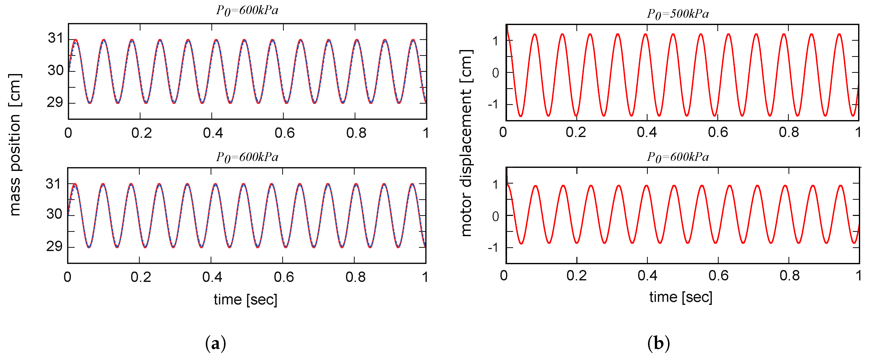
In the simulation, a PAM with 15 cm unloaded length is filled with a specific amount of air (fixed air mass). The amount of inflated air pressure in PAM is not added during motion meaning the valves are closed and the desired unloaded pressure is adjusted beforehand. Indeed, the PAM pressure is changing during experiment due to variation of the muscle length, but the amount of air is fixed by closing the valves as mentioned before. To follow the desired sinusoidal movement of the mass, the EM is controlled with a PID controller. The amplitude of the periodic movements is 1 cm and the bias of sine wave is 30 cm. The range of mass displacement (2 cm) is resulted from the EPA actuator movement. This number is comparable to human muscle length changes in walking and is also higher than the motion range in BioBiped3 experiments (see Section 2.3.2). Another reason for defining this motion range is because of the PAM length. Due to the PAM contraction, which is 20–25% of the muscle length, for a 15 cm length PAM, the maximum contraction will be less than 4 cm. We considered half of this number to assure that the EPA works on the identified range of the PAM. To apply such an actuator for locomotion, tuning lever arm helps increase joint movement range.
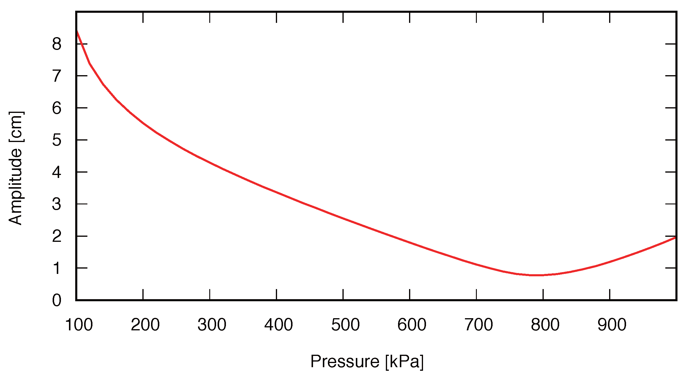
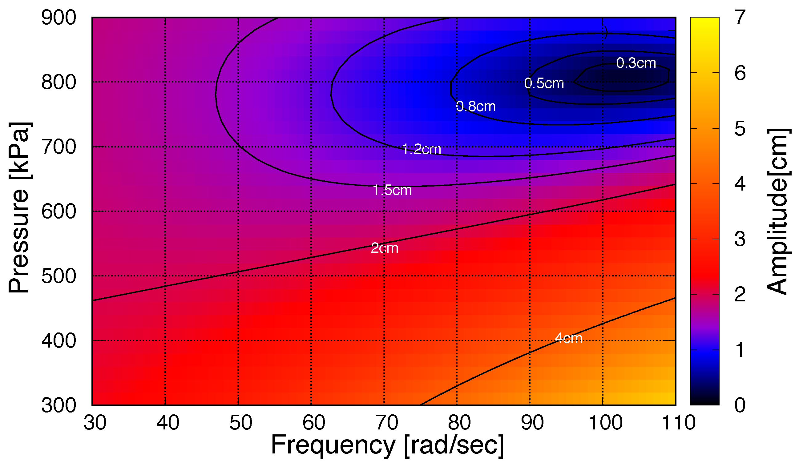
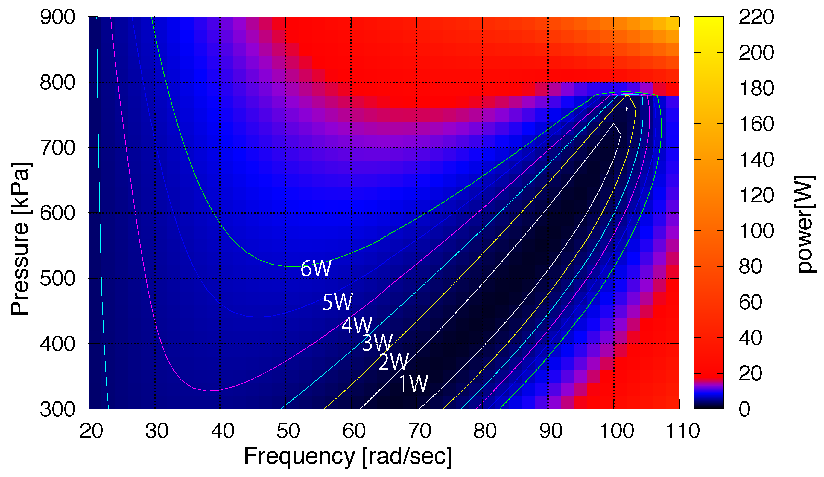
The periodic movement is characterized by the frequency of the reference sinusoidal signal (ranging from 20 rad/s to 110 rad/s). At each motion frequency, the optimal pressure is found by minimizing the motor movement. Therefore, by adjusting the PAM pressure to its optimal value, the least EM movement can be applied to control the robot joint at each frequency. The simulation results of the EPA model are described in Section 3.2.

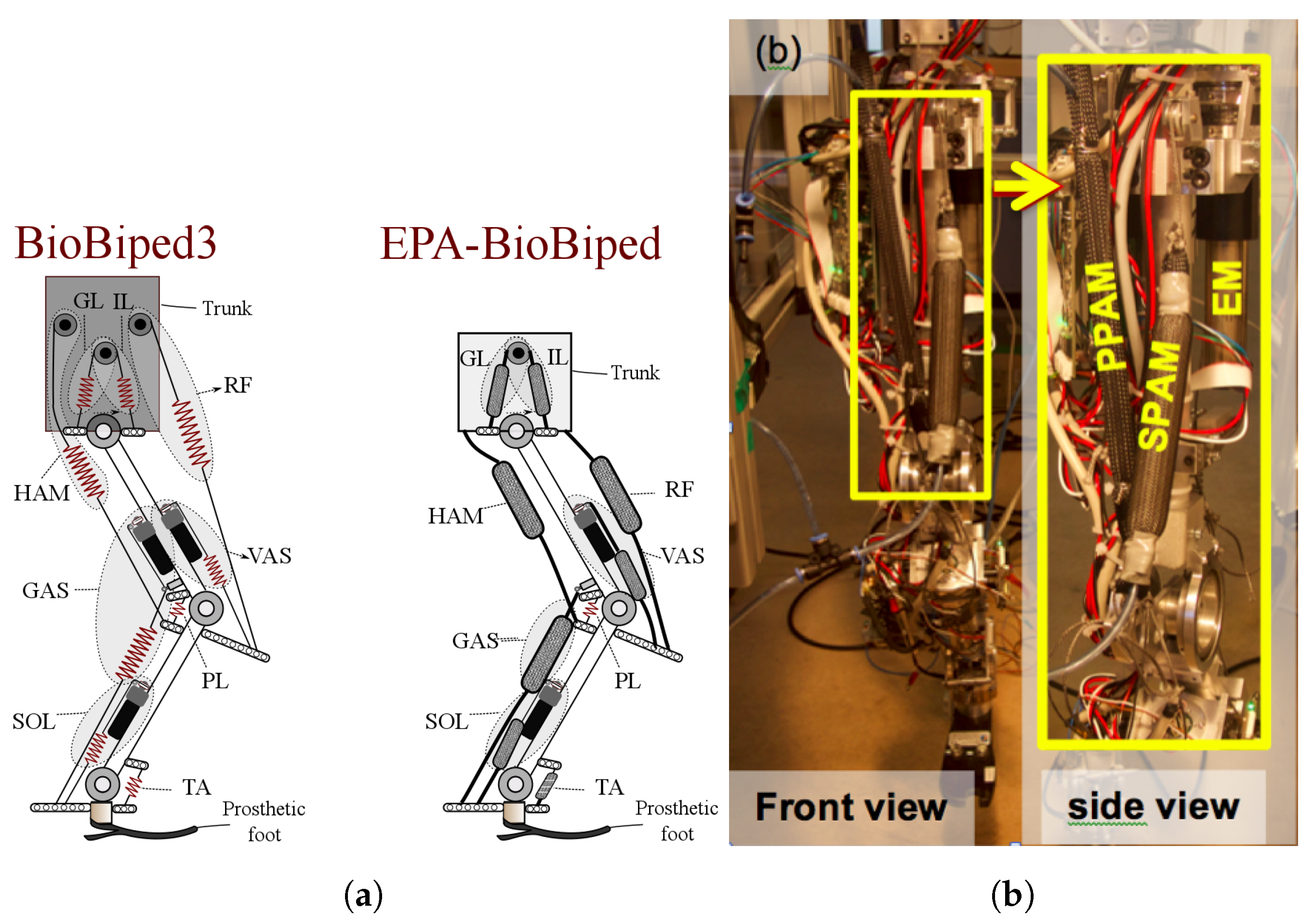
2.3.2. Hardware Experiment

The concept of EPA is not constrained to a specific arrangement of actuators. The PAM can be attached to the EM in both serial, parallel or antagonistic arrangement. Recently, studies on considering parallel stiffness to the SEA (called SPEA) address the issues existing in SEAs (e.g., SEA cannot reduce the consumed torque [8,17]). Effects of parallel stiffness on reducing peak power and energy consumption of the actuator in prosthesis were described and compared with serial stiffness in [12]. Thus, we investigate the effect of PAM compliance adjustment in energy consumption of the EPA.
In Figure 3a, the schematic of Biobiped3 robot ([21] and the concept of EPA-instrument BioBiped robot (http://www.biobiped.de) are illustrated. In Figure 3b, the SEA for the vastus muscle is replaced by an EPA in which two PAMs are applied in series (SPAM) and in parallel (PPAM) to the actuator. In Section 3.3, we show that different arrangements and stiffness adjustment through tuning the PAM pressure yield more efficient motion control. In this experiment, we fixed the robot trunk and employed the knee actuator to generate a periodic movement at different frequencies. The desired joint position was given by a sinusoidal signal, in which the frequency was increasing linearly from 0.5 Hz to 2 Hz in 5 min. Here, the knee movement is 10 ° which mimics human knee movement during stance phase of walking at 1 m/s [30]. In our experiment, this results in 7.5 cm movement in the foot, as the hip is fixed. This motion requires about 1 cm variation in the SEA length which is in the motion range defined in simulations.
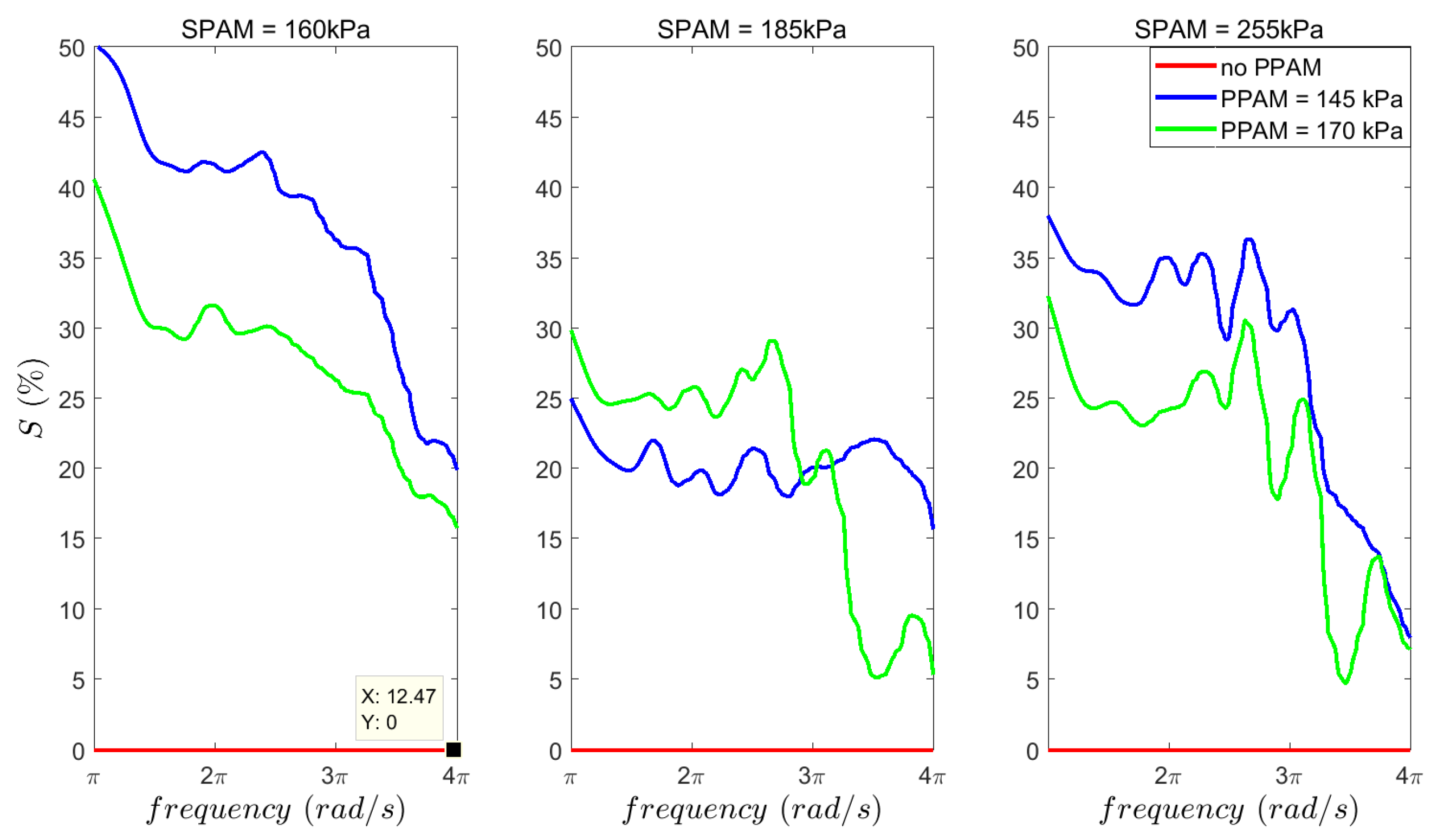
In our experiments, the effects of SPAM and PPAM pressures on energy consumption at different frequencies are considered to analyze the effect of the PAM on efficiency of the actuator. The integrated current square was used as a measure of energy consumption.
E = T I 2 d t
in which I is the motor current and T is the period of the sinusoidal signal. The computed term E based on the consumed current can be used as a measure for electric energy while the movement patterns are kept fixed. This parameter is computed for different values of PPAM and SPAM stiffness (air pressure) to investigate the effectiveness of EPA concept. It is shown that by tuning PAM’s air pressure, more efficiency at each frequency can be achieved. Therefore, in order to control locomotion that can be described by combinations of different oscillatory movements, the optimal stiffness (equivalently air pressure) should be found to work in a range of optimal solutions.

3. Results

This section comprises three different studies. First, we show the PAM identification outcomes with our dynamic model and compare its performance to the two other models. Then, the results of the EPA simulation model demonstrate the advantages of this novel actuator. It is shown that muscle pressure is an important parameter to adjust the actuator impedance (stiffness) and can yield an efficient control of EM for a desired periodic movement of the connected mass. Finally, the experimental results of applying EPA for actuating the knee joint of the BioBiped3 robot are presented.

3.1. PAM Identification

Here, we compare the three models of PAM (our model with the static and dynamics models explained in Section 2.2) regarding their abilities in prediction of our experiments (described in Section 2.1). The coefficients of Equation (8) to approximate the PAM model in the experiments are calculated as C 1 = 2 . 42 , C 2 = 0 . 22 , C 3 = 1 . 56 , C 4 = 0 . 19 and C 5 = 5 . 4 × 10 4 . Comparison among the static model, the dynamic model of Tang et al. and our model is presented in Table 1. On the one hand, the R 2 correlation shows that the precision of the dynamic model of Tang et al. is slightly higher that the static model. Therefore, this model can perfectly describe their experimental setup and does not have significant advantages (compared to the static model) to be employed in EPA modeling. On the other hand, the static model is not sufficient for describing the dynamic behavior of the PAM, e.g., hysteresis. Due to higher correlation between the experimental data and our proposed dynamic model, it is clearly preferred to other models.
In order to investigate the relation between different parameters of the the muscle states (length, speed and pressure) and the resulted force, the identification results are shown in Figure 4. Different branches observed in the 3D figure are related to different trials with different initial pressures ( P 0 ). It is observed that different branches have similar shapes. This figure shows that faster elongation (yellow color) results in lower force. Having shorter muscle length has similar effect. Although the relation between force and length in Equation (8) is linear, the curves in the force–length plane (bottom right) are not linear. Here, the effect of hysteresis is visible which can be explained by dependency to the velocity. In addition, higher force can be produced by increasing muscle pressure (resulting in length reduction) and decreasing contraction speed which is expected. Unlike force–length, the curves in the force-pressure plane (right-middle) looks linear while their relation in Equation (8) is nonlinear. Because of the coupling between different states, focusing at subs-paces of the 4D space is not very informative. This figure depicts that the muscle has a nonlinear force-length relation besides a damping behavior like human muscle. The air pressure level can be considered as an activation level in biological muscle. This model is utilized in the EPA simulation experiment described in the next section.

3.2. EPA Simulation Results

The simulation model of Figure 1b—explained in Section 2.2— is employed to evaluate EPA concept. For that, the EM is controlled to move the mass to follow a desired periodic movement. This is done using different (initial) pressures of the PAM muscle in the no-load condition. For a sinusoidal motion of the mass with a desired frequency, EM position is controlled using a PID controller. The required movement of the EM with respect to the desired mass motion shows the efficiency of the actuator for the specified task. In the following figures, “Amplitude” is the peak-to-peak displacement of the motor (this value for the mass is 2 cm).
In the first simulation, we set the frequency to 80 rad/s and compare the effects of two different values for initial pressure ( P 0 ) on the EM movement. In Figure 5, the results are shown for 500 kPa and 600 kPa as the initial PAM pressure values. The figures of the left panel (Figure 5a) demonstrate the applicability of the EPA for tracking a desired trajectory. In spite of nonlinear and complex dynamics of the PAM (including hysteresis) a simple PID is sufficient for this position control. The desired and controlled mass positions at both frequencies depict high precision of control with EPA although, it has relatively low impedance compared to EM and even other VIAs. Furthermore, for similar mass motions the EM movement differs due to the corresponding P 0 , as shown in Figure 5a. The required motor displacement for the same mass movement is reduced by increasing the PAM initial pressure (equivalently, increasing the actuator stiffness). This corresponds to the frequency of the desired periodic motion.
Figure 6 shows the EM displacement amplitude for a desired sinusoidal movement of the mass with frequency 80 rad/s while P 0 is varying from 100 kPa to 1000 kPa. It is observed that the minimum motor movement is obtained at about 800 kPa meaning that this is the optimal pressure (resulting in optimal impedance) of the EPA as a variable impedance actuator. Therefore, if the required leg movement for a specific gait uses such a frequency, by adjusting the PAM pressure and closing the valves the EM movement is minimized. It is remarkable that after setting the pressure by inflating the muscles, the desired movement is performed by the small EM motion and the PAM only consumes very little energy caused by friction and damping effects in the PAM. Since valves are closed and no energy is required to actuate PAMs, the required energy to actuate the PAM is just once for impedance adjustment which can be ignored in a periodic movement with numerous cycles.
The optimal pressure varies if the desired movement frequency changes, as shown in Figure 7. From this figure, the optimal pressure has a significant role in EM displacement specially in periodic movement with higher frequencies. It is important that in a large region in the movement range, the EM displacement is less than mass movement (2 cm). In case of using rigid actuator (direct drive), the EM movement is always equal to 2 cm. This motion reduction (from mass to EM) is much more significant in fast movements (frequencies more than 80 rad/s). For motion frequencies between 95 rad/s to 110 rad/s, the required motor movement will reduce to 15% of the mass motion (rigid actuator). Setting the PAM pressure to 800 kPa can minimize the EM motion in most of the frequencies.
The proper impedance adjustment through the PAM can significantly improve the actuator movement. However, this might be different from the maximum required power in the motor. In Figure 8 the peak power values of EM are illustrated in color, versus the PAM preloaded pressure and desired movement frequency. It is observed that tuning P 0 can significantly reduce the peak power. In addition, a clear monotonic relationship between the PAM pressure and movement frequency can be detected from 60 rad/s to 100 rad/s, depicted by the black region. It means that if higher frequency is required, the EM peak power can be significantly reduced by increasing the PAM pressure (equivalently impedance). This is different from the preferred pressure to minimize EM motion (Figure 7). Therefore, different control targets can be achieved using EPA design.

3.3. Hardware Experimental Results

In this section, we explain the results of experiments with BioBiped3 robot (Section 2.3.2). In Figure 9, nine different conditions are compared regarding the effects of SPAM and PPAM pressures on energy consumption at different frequencies. These experiments are categorized in three groups with respect to the serial PAM (SPAM) pressure. Then, for each group three different conditions include one experiment without parallel PAM (PPAM) and two conditions with different pressure values of PPAM. Here, we use Equation (9) to calculate the consumed energy. For each group, saved energy (S) is defined by the difference between the consumed energy of that trial ( E p ) and the energy of the one from the same group without PPAM ( E 0 ) as follows.
S = E P E 0 E 0
This value shows the saved energy at each frequency compared to the no PPAM case of the same group. In Figure 9 the numbers are presented in percent. For a fixed SPAM, the consumed energy is the maximum for no PPAM arrangement. Conclusively, adding PPAM reduces energy consumption. In addition, comparing nonzero pressures for PPAM shows that for a specific SPAM, the frequency determines which stiffness (respectively, air pressure) reduces energy consumption the most. For example, when SPAM = 185 kPa, for frequencies below 3 π rad/s (1.5 Hz), the saved energy S for PPAM = 170 kPa is more than that of PPAM = 145 kPa, whereas for frequencies above 1.5 Hz, PPAM = 145 kPa is more efficient. Similar argumentation are valid for SPAM. Therefore, to move with a certain frequency, stiffness adjustment of the PAMs can result in reduction of energy consumption and peak power. It means that, for changing the locomotion condition (e.g., motion speed), tuning PAMs may result in reducing energy consumption in EPAs. The left figure shows another pattern in which the saved energy for one pressure value of the parallel PAM (145 kPa) is always higher than the other value (170 kPa). In such a case, the PPAM pressure can be set to the lower value for the whole range of motion frequencies.
These results show a wide range of improvement in energy consumption that can be achieved by different combination of SPAM and PPAM in EPA design. In order to benefit from these properties of the newly developed actuator, the complete catalog of consumed energy with respect to different arrangement and adjustment of PAM and EM should be identified. Using an optimization approach, the optimal design and control can be obtained for each gait condition.

4. Discussion

Muscles are arguably the best-known actuation technology that approaches a perfect force source i.e., one with extremely low impedance (perfectly back-drivable) and stiction, although with only moderate bandwidth [7]. Inspired by the functional performance and neuromechanical control of biological muscles [31], appropriate design of the actuator and control strategies can largely enhance the locomotor function. If a robot without any passive compliance jumps or runs, even with precise force feedback control to have active compliance [32,33], it has to cope with energy losses and compensate delay effects [34]. Adaptable compliances as found in biological systems provide significant advantages over traditional actuation for legged robots and assistive devices (e.g., orthoses, prostheses). Although VIAs are rapidly developing with a wide range of different actuators, there is no “winning” design, but rather application-dependent optimal solutions [15]. In this paper, we address this problem by developing a novel actuator namely EPA, comprised of electric motors and pneumatic air muscles. Preliminary simulation and experimental results presented in the previous sections support the idea of approaching human muscle features with the EPA.
PAM-driven biped robots can walk stably and perform efficient hopping and running steps without any feedback [34]. PAMs also provide adjustable compliance supporting periodic movements [22]. However, due to difficulties in force control and nonlinear air pressure–force behavior in PAMs, providing an analytical approach for stabilizing PAM-actuated legged systems is problematic. In these systems, stability is usually obtained by hand tuning of control parameters and is rarely investigated analytically. Combining the EM and PAM into an EPA may help improve controllability and overcome the drawbacks of each actuator type (e.g., increasing the bandwidth of PAMs by adding parallel EM in Macro-Mini scheme [35]). The main hypothesis that is investigated in this paper was as follows: The combination of PAM and EM permits a variety of arrangements which may enable this hybrid actuator to outperform existing actuators in efficiency over the operational region required for human-like locomotion which is a combination of periodic tasks in the steady state. To verify this hypothesis and benefit from properties of different actuators (PAM and EM) in EPA, first we need to have better understanding of their dynamical behavior. In human muscle-tendon-complex (MTC), actuation comes from the muscle during activation, while passive behavior is resulted from both tendon and muscle properties. In EPA, we consider EM to develop force as an active part, while the PAM is used as an adjustable compliance (passive). Although in future application of EPA, PAM can be also used to inject energy to the system as an actuators, here we did not investigate this property of PAMs. In order to enhance our understanding or PAM, a new dynamic model was developed which was used in simulation studies. In spite of the nonlinear and complex dynamical behavior of PAMs together with hysteresis, impedance (or stiffness) adjustment can be easily implemented by changing the PAM pressure. This is a simple approach to adapt the passive behavior of the EPA. Therefore, in our simulations and experiments we did not control PAM pressure continuously. In that sense, the control complexity is similar to that of SEA. Definitely, if we need continuous adaptation of PAM pressure, we need another control layer. However, the idea can be extended by identifying different behavioral regimes corresponding to muscle stiffness and using the same control architecture for continuous impedance adjustment. Hence, the higher complexity of EPA control compared to SEA relates to selecting the optimal stiffness for the targeted task (gait). For example if a linear relation between frequency and optimal pressure can be found (as shown by black region in Figure 8), the control rule for selecting optimal pressure of PAM will be also very simple. This shows that, the nonlinearity of the PAM model and dependence to muscle length change (speed L ˙ ) does not necessarily affect the control principle, significantly. As a result, using PAM as an adjustable stiffness is a practical solution for optimizing actuator dynamics for locomotion without significant increase of control complexity.
Based on the simulation results in Section 3.2, for a repetitive motion in a certain time, the PAM in EPA is able to supply optimal compliance for producing desired periodic movements with low energy and simple design (in comparison to other VIAs [22]). Supposed to the insignificance of air leakage on the valves, the longer the executing time of such a repetitive movement, the more efficiency obtained with the EPA actuation mechanism. This results from event based adjustment of the PAM muscle to provide the required compliance for the corresponding motion time.
As shown in this paper, using PAM instead of springs in a SEA configuration allows us to adjust the compliance as in VIAs. This makes the system more efficient (compared to EM) and more robust against impacts (not shown). In the future, we will compare this actuator with other VIAs regarding performance, efficiency and robustness against perturbations. The addition of a parallel PAM to this design (as an adjustable passive compliance) can also reduce EM torque when not all of the torque passes through the motor. Studies on parallel stiffness show that this resolves a main drawback of compliant actuators with series compliance [8,9] which are in line with our findings in experiments with BioBiped3 robot. To examine the applicability of the actuator for legged locomotion, our next step is implementing the EPA on the 1D hopper robot (MARC-Hopper-II, [36]) to perform robust and efficient hopping and compare it with other compliant actuators. Furthermore, with this new combination, we can also benefit from muscle-like properties of lightweight PAMs [20], e.g., using compliance control techniques [22]. As different (biological) muscles may have different functions during a specific task (e.g., operating as spring, drives or brakes), this can be represented by a muscle-specific design of EPA, as combinations of PAM and EM (e.g., with series, parallel, antagonistic arrangements).
Based on its mechanical properties and its flexible arrangement in multi-segment-systems, the EPA provides a novel actuator, which mimics human muscle function and is able to mechanically adapt to different gaits and conditions (e.g., locomotion speed). With EPA technology, new versatile and efficient locomotor systems for a wide range of applications can be designed.

Acknowledgments

This research was supported in part by the German Research Foundation (DFG) under grants No. AH307/2-1 and SE1042/29-1.

Author Contributions

Maziar A. Sharbafi is the corresponding author of the article, responsible for the conception and design of simulations and experiments, analyses and interpretation of data and writing of the manuscript. Hirofumi Shin developed the simulation model and experimental setup for identifying PAM. He conducted the simulation studies and analyzed the results and contributed to writing the paper. Guoping Zhao was involved in setting the identification setup and conducted the experiments with BioBiped3 and helped in revising the paper. Koh Hosoda and Andre Seyfarth were the supervisors of the project from the two groups involved in this project. Andre Seyfarth provided fundamental ideas to the EPA project and its successful funding by the German Research Foundation DFG.

Conflicts of Interest

The authors declare no conflict of interest. The founding sponsors had no role in the design of the study; in the collection, analyses, or interpretation of data; in the writing of the manuscript, and in the decision to publish the results.

References

  1. Sakagami, Y.; Watanabe, R.; Aoyama, C.; Matsunaga, S.; Higaki, N.; Fujimura, K. The intelligent ASIMO: System overview and integration. In Proceedings of the IEEE/RSJ International Conference on Intelligent Robots and Systems, Lausanne, Switzerland, 30 September–4 October 2002; pp. 2478–2483. [Google Scholar]
  2. Kaneko, K.; Kanehiro, F.; Morisawa, M.; Akachi, K.; Miyamori, G.; Hayashi, A.; Kanehira, N. Humanoid robot HRP-4-humanoid robotics platform with lightweight and slim body. In Proceedings of the 2011 IEEE/RSJ International Conference on Intelligent Robots and Systems, San Francisco, CA, USA, 25–30 September 2011; pp. 4400–4407. [Google Scholar]
  3. Pratt, G.A.; Williamson, M.M. Series elastic actuators. In Proceedings of the 1995 IEEE/RSJ International Conference on Intelligent Robots and Systems. Human Robot Interaction and Cooperative Robots, Pittsburgh, PA, USA, 5–9 August 1995; pp. 399–406. [Google Scholar]
  4. Robinson, D.W.; Pratt, J.E.; Paluska, D.J.; Pratt, G.A. Series elastic actuator development for a biomimetic walking robot. In Proceedings of the 1999 IEEE/ASME International Conference on Advanced Intelligent Mechatronics (Cat. No.99TH8399), Atlanta, GA, USA, 19–23 September 1999; pp. 561–568. [Google Scholar]
  5. Pratt, J.; Krupp, B. Design of a bipedal walking robot. Proc. SPIE 2008, 6962. [Google Scholar] [CrossRef]
  6. Radkhah, K.; Maufroy, C.; Maus, M.; Scholz, D.; Seyfarth, A.; von Stryk, O. Concept and design of the Biobiped1 robot for human-like walking and running. Int. J. Hum. Robot. 2011, 8, 439–458. [Google Scholar] [CrossRef]
  7. Pratt, J.E.; Krupp, B.T. Series elastic actuators for legged robots. Proc. SPIE 2004, 5422. [Google Scholar] [CrossRef]
  8. Mathijssen, G.; Lefeber, D.; Vanderborght, B. Variable recruitment of parallel elastic elements: Series–parallel elastic actuators (SPEA) with dephased mutilated gears. IEEE/ASME Trans. Mechatron. 2015, 20, 594–602. [Google Scholar] [CrossRef]
  9. Grimmer, M.; Eslamy, M.; Seyfarth, A. Energetic and Peak Power Advantages of Series Elastic Actuators in an Actuated Prosthetic Leg for Walking and Running. Actuators 2014, 3, 1–19. [Google Scholar] [CrossRef]
  10. Komi, P.V. Stretch-shortening cycle. Strength Power Sport 2008, 3, 184–202. [Google Scholar]
  11. Farley, C.T.; Houdijk, H.H.; Van Strien, C.; Louie, M. Mechanism of leg stiffness adjustment for hopping on surfaces of different stiffnesses. J. Appl. Physiol. 1998, 85, 1044–1055. [Google Scholar] [PubMed]
  12. Grimmer, M.; Eslamy, M.; Gliech, S.; Seyfarth, A. A comparison of parallel-and series elastic elements in an actuator for mimicking human ankle joint in walking and running. In Proceedings of the 2012 IEEE International Conference on Robotics and Automation, Saint Paul, MN, USA, 14–18 May 2012; pp. 2463–2470. [Google Scholar]
  13. Müller, R.; Ernst, M.; Blickhan, R. Leg adjustments during running across visible and camouflaged incidental changes in ground level. J. Exp. Biol. 2012, 215, 3072–3079. [Google Scholar] [CrossRef] [PubMed]
  14. Sharbafi, M.A.; Seyfarth, A. How locomotion sub-functions can control walking at different speeds? J. Biomech. 2017, 53, 163–170. [Google Scholar] [CrossRef] [PubMed]
  15. Vanderborght, B.; Albu-Schäffer, A.; Bicchi, A.; Burdet, E.; Caldwell, D.G.; Carloni, R.; Catalano, M.; Eiberger, O.; Friedl, W.; Ganesh, G.; et al. Variable impedance actuators: A review. Robot. Auton. Syst. 2013, 61, 1601–1614. [Google Scholar] [CrossRef]
  16. Van Ham, R.; Vanderborght, B.; Van Damme, M.; Verrelst, B.; Lefeber, D. MACCEPA, the mechanically adjustable compliance and controllable equilibrium position actuator: Design and implementation in a biped robot. Robot. Auton. Syst. 2007, 55, 761–768. [Google Scholar] [CrossRef]
  17. Mettin, U.; La Hera, P.X.; Freidovich, L.B.; Shiriaev, A.S. Parallel elastic actuators as control tool for preplanned trajectories of underactuated mechanical systems. Int. J. Robot. Res. 2010, 29, 1186–1198. [Google Scholar] [CrossRef]
  18. Wisse, M.; van der Linde, R.Q. Delft Pneumatic Bipeds; Springer: Berlin, Germany, 2007; Volume 34. [Google Scholar]
  19. Verrelst, B.; Van Ham, R.; Vanderborght, B.; Daerden, F.; Lefeber, D.; Vermeulen, J. The pneumatic biped “Lucy” actuated with pleated pneumatic artificial muscles. Auton. Robots 2005, 18, 201–213. [Google Scholar] [CrossRef]
  20. Klute, G.K.; Czerniecki, J.M.; Hannaford, B. McKibben artificial muscles: pneumatic actuators with biomechanical intelligence. In Proceedings of the 1999 IEEE/ASME International Conference on Advanced Intelligent Mechatronics (Cat. No.99TH8399), Atlanta, GA, USA, 19–23 September 1999; pp. 221–226. [Google Scholar]
  21. Sharbafi, M.A.; Rode, C.; Kurowski, S.; Scholz, D.; Möckel, R.; Radkhah, K.; Zhao, G.; Rashty, A.M.; von Stryk, O.; Seyfarth, A. A new biarticular actuator design facilitates control of leg function in BioBiped3. Bioinspir. Biomim. 2016, 11, 046003. [Google Scholar] [CrossRef] [PubMed]
  22. Vanderborght, B.; Verrelst, B.; Van Ham, R.; Van Damme, M.; Lefeber, D.; Duran, B.M.Y.; Beyl, P. Exploiting natural dynamics to reduce energy consumption by controlling the compliance of soft actuators. Int. J. Robot. Res. 2006, 25, 343–358. [Google Scholar] [CrossRef]
  23. Chou, C.P.; Hannaford, B. Measurement and modeling of McKibben pneumatic artificial muscles. IEEE Trans. Robot. Auton. 1996, 12, 90–102. [Google Scholar] [CrossRef]
  24. Doumit, M.; Fahim, A.; Munro, M. Analytical Modeling and Experimental Validation of the Braided Pneumatic Muscle. IEEE Trans. Robot. 2009, 25, 1282–1291. [Google Scholar] [CrossRef]
  25. Kogiso, K.; Sawano, K.; Itto, T.; Sugimoto, K. Identification procedure for McKibben pneumatic artificial muscle systems. In Proceedings of the 2012 IEEE/RSJ International Conference on Intelligent Robots and Systems, Vilamoura, Portugal, 7–12 October 2012; pp. 3714–3721. [Google Scholar]
  26. Tang, R.; Liu, D. An enhanced dynamic model for McKibben pneumatic muscle actuators. In Proceedings of the Australasian Conference on Robotics and Automation, Wellington, NZ, USA, 3–5 December 2012. [Google Scholar]
  27. Tondu, B.; Lopez, P. Modeling and control of McKibben artificial muscle robot actuators. IEEE Control Syst. 2000, 20, 15–38. [Google Scholar] [CrossRef]
  28. Colbrunn, R.W.; Nelson, G.M.; Quinn, R.D. Modeling of braided pneumatic actuators for robotic control. In Proceedings of the 2001 IEEE/RSJ International Conference on Intelligent Robots and Systems. Expanding the Societal Role of Robotics in the the Next Millennium (Cat. No.01CH37180), Maui, HI, USA, 29 October–3 November 2001; pp. 1964–1970. [Google Scholar]
  29. Park, Y.L.; Santos, J.; Galloway, K.G.; Goldfield, E.C.; Wood, R.J. A soft wearable robotic device for active knee motions using flat pneumatic artificial muscles. In Proceedings of the 2014 IEEE International Conference on Robotics and Automation (ICRA), Hong Kong, China, 31 May–7 June 2014; pp. 4805–4810. [Google Scholar]
  30. Lipfert, S.W. Kinematic and Dynamic Similarities Between Walking and Running; Verlag Dr. Kovac: Hamburg, Germany, 2010. [Google Scholar]
  31. Nishikawa, K.; Biewener, A.A.; Aerts, P.; Ahn, A.N.; Chiel, H.J.; Daley, M.A.; Daniel, T.L.; Full, R.J.; Hale, M.E.; Hedrick, T.L.; et al. Neuromechanics: An integrative approach for understanding motor control. Integr. Comp. Biol. 2007, 47, 16–54. [Google Scholar] [CrossRef] [PubMed]
  32. Semini, C.; Tsagarakis, N.G.; Guglielmino, E.; Focchi, M.; Cannella, F.; Caldwell, D.G. Design of HyQ—A hydraulically and electrically actuated quadruped robot. J. Syst. Control Eng. 2011, 225, 831–849. [Google Scholar] [CrossRef]
  33. Semini, C.; Barasuol, V.; Boaventura, T.; Frigerio, M.; Focchi, M.; Caldwell, D.G.; Buchli, J. Towards versatile legged robots through active impedance control. Int. J. Robot. Res. 2015, 34, 1003–1020. [Google Scholar] [CrossRef]
  34. Hosoda, K.; Takuma, T.; Nakamoto, A.; Hayashi, S. Biped robot design powered by antagonistic pneumatic actuators for multi-modal locomotion. Robot. Auton. Syst. 2008, 56, 46–53. [Google Scholar] [CrossRef]
  35. Sardellitti, I.; Park, J.; Shin, D.; Khatib, O. Air muscle controller design in the distributed macro-mini (DM 2) actuation approach. In Proceedings of the 2007 IEEE/RSJ International Conference on Intelligent Robots and Systems, San Diego, CA, USA, 29 October–2 November 2007; pp. 1822–1827. [Google Scholar]
  36. Oehlke, J.; Sharbafi, M.A.; Beckerle, P.; Seyfarth, A. Template-based hopping control of a bio-inspired segmented robotic leg. In Proceedings of the 2016 6th IEEE International Conference on Biomedical Robotics and Biomechatronics (BioRob), Singapore, 26–29 June 2016; pp. 35–40. [Google Scholar]
Figure 1. (a) A sample design on an EPA (Electric-Pneumatic Actuator) for bipedal locomotion control; and (b) the setup for evaluating EPA concept. A fixed mass is connected to serially connected PAM and EM. A desired sinusoidal mass movement is the reference trajectory and the EM controls that with different PAM pressures.
Actuators 06 00030 g001
Figure 2. Geometry of McKibben type pneumatic artificial muscle (PAM). the left figure shows the PAM. The middle figure shows a thread of the PAM. The right figure shows the length and angle how the thread wounds the PAM.
Actuators 06 00030 g002
Figure 3. (a) Schematic of the BioBiped3 robot series and the concept for an EPA-instrumented BioBiped by replacing SEAs with EPAs and passive springs with PAMs; and (b) implementation of EPA in BioBiped3 representing the Vastus muscle, including one electric motor (EM), one serial (SPAM) and one parallel PAM (PPAM).
Actuators 06 00030 g003
Figure 4. Identified model of PAM. (left) The muscle length, pressure and force are shown with the three axes. The color shows the muscle length contraction speed (negative). (right) The three subfigures show the relations in the 2D for illustrating relation between different muscle parameters which are not clear in 3D curves.
Actuators 06 00030 g004
Figure 5. The mass and motor position. The no-load (initial) muscle pressure are 500 kPa and 600 kPa in top and bottom graphs, respectively. (a) The desired (red solid lines) and actual (blue dashed line) trajectory of mass position; and (b) the trajectory of motor position of the EPA.
Actuators 06 00030 g005
Figure 6. The changes in amplitude of motor position when desired mass position is the periodic movement given by p ( t ) = 0.3 + 0.01 sin ( 80 t ) .
Actuators 06 00030 g006
Figure 7. The relationship between the desired periodic movement frequency, the PAM preloaded pressure and the EM displacement (amplitude). Defining ω as the periodic motion frequency, the desired mass position is given by p ( t ) = 0.3 + 0.01 sin ( ω t ) .
Actuators 06 00030 g007
Figure 8. The relationship between the desired periodic movement frequency, the PAM preloaded pressure and the EM peak power. Defining ω as the periodic motion frequency, the desired mass position is given by p ( t ) = 0.3 + 0.01 sin ( ω t ) .
Actuators 06 00030 g008
Figure 9. Integration of PAM in BioBiped3. Implementation of EPA in BioBiped3 representing the Vastus muscle, including one electric motor (EM), one serial (SPAM) and one parallel PAM (PPAM). The knee joint angle is PID controlled. The desired joint position is a sinusoidal wave with frequency linearly increasing from π rad/s to 4 π rad/s (0.5 Hz to 2 Hz), over a period of 5 min. The approximation of saved energy (S) compared to no PPAM case is shown for different PAM pressures and oscillations frequencies. The atmosphere pressure is about 100 kPa.
Actuators 06 00030 g009
Table 1. Comparison between different PAM models.
ParametersStatic ModelTang Dynamic ModelOur Dynamic Model
R 2 Correlation0.9160.9210.971
Including Damping EffectNoYesYes
HysteresisNoYesYes

