1. Introduction
The development of bending actuators exploiting different operating principles has been focused upon by the research community to address needs arising from applications, such as robotics, positioning and micro-positioning and biomimetic devices (e.g., artificial muscles). Depending on the application, small or large deflection can be required and the required loading features must be adapted. As an example, small deflections are strategic for micro-positioning, while large deflections are required in the robotic field and also for the development of artificial muscles. The development of actuators requires competency from the point of view of technology, materials, electronics and control engineering.
Many functional materials have been tested as potential functional layers for the implementation of bending actuators. Non exhaustive examples are piezoelectric, macro fiber composites (MFC), electrostrictive materials, carbon nanotubes (CNT), elastomers, driven by an electric field, magnetostrictive materials and magnetoelectric composites, driven by a magnetic field, as well as temperature controllable materials (such as bimorph and shape memory alloys). In [
1] a full review of above actuation mechanism is addressed, while specific contributions are available in [
2,
3,
4,
5,
6,
7,
8,
9].
Piezoelectrics have been largely adopted to develop bending actuators. Among such materials, multilayer piezoelectrics are able to produce large force at low voltage with a restricted displacement, while bimorphs which are able to produce large displacement, although in the order of hundreds of micrometers, show a low loading feature [
1].
In case large deflection is required, ElectroActive Polymers (EAP) can be considered as a convenient functional layer to realize high bending actuators. A thorough review of polymer actuators is presented in [
10].
EAP, which show large deflection, lightweight, flexibility and low cost, can be classified into two classes: Dielectric and Ionic. Dielectric EAP require large driving voltage to produce high electric fields and consequently high strains. Examples of such materials, which do not require energy to stand at a fixed position, are electrostrictive polymers and dielectric elastomers [
11].
The working principle of Ionic EAP is based on the displacement of ions inside the polymer. Actuators exploiting these materials can show very large deflection with few volts of driving, but must be powered to keep the device in a fixed position. Among Ionic EAP, conductive polymers and Ionic polymer-metal composites (IPMCs) have to be cited [
12]. IPMCs consist of ionic polymer (e.g., Nafion) with conductors patterned on its surfaces. One point still to be focused upon is the necessity for them to work in a wet environment.
Among the ionic based actuators, those based on carbon nanotubes show interesting properties [
13]. As an example, a new low-voltage, and easy-operable bending actuator based on aligned carbon nanotube/polymer composites is presented in [
14].
Another class of actuators is that which exploits an electromagnetic actuation principle, such as Lorentz force and permanent magnets based configurations [
15,
16,
17]. These devices, which exhibit good performances in terms of displacement and force also when low current is operated, can be conveniently adopted when low power and displacement on a millimeter scale are required.
Moving from materials to technologies, it can be affirmed that in the past 10 years the scientific community has shown a growing interest in the possibility to realize very low-cost electronics and actuators which exploit printing technologies, low cost materials and flexible substrates. This interest is driven by needs for low cost mass-production processes [
18,
19].
Low cost flexible actuators can be conveniently used in many application contexts, for example where the use of disposable devices is required. Moreover, the rapid prototyping of cheap devices by direct printing technologies is also of great interest for the scientific community including research laboratories and academies.
As an example, in [
20] an inkjet-printed piezoelectric polymer actuator based on poly(vinyledene fluoride trifluoroethylene) (P(VDF-TrFE)) and electrodes printed from silver nanoparticle dispersions is presented. The device operates in the micro-scale and requires driving voltage in the order of hundreds of volts.
Despite high performances of a high voltage operated device, as highlighted above, the need for low voltage, easy to use and cheap actuators emerges also in application contexts addressed by the printing technology.
In this paper an electromagnetic driven actuator, fully developed by a low cost Inkjet Printing (IJP) technology is presented. The device can be suitably applied for positioning applications in the millimeter range with a required loading in the order of hundreds of µN. The actuator is also equipped with an embedded strain sensing feature implemented by an IJP resistive sensor.
Advantages of the proposed actuation architecture are related to the double position control mechanism (by an external DC magnetic field or a driving current), the embedded strain sensing feature, the layout flexibility and easy to adapt to application requirements and the low cost technology and materials adopted.
In the following section a brief overview of IJP technology is given. The actuation strategy and the device implementation are presented in
Section 3, while the experimental results are shown in
Section 4.
2. An Overview of InkJet Printing Technology
For the sake of convenience, in the following few notes, we report on printing technologies with a specific focus on IJP.
Two main printing technologies are used in the field of actuators: screen printing and InkJet Printing. By screen Printing, which is based on the use of masks and a roller pressure mechanism, conductive, insulating and other functional materials can be printed on the substrate. The need for masks and its consequent physical interaction with the substrate are main drawbacks of screen printing techniques. Examples of sensors realized by screen printing are available in [
21,
22,
23].
In contrast to screen printing, inkjet printing is a mask-less drop-on-demand technique which allows for the deposition of well-defined and complex topology without the need for patterning techniques. Among materials available for InkJet Printing, conductive metal inks and polymers (such as PEDOT-PSS) and functional polymers (such as polyaniline, PANI) can be listed [
24,
25,
26,
27,
28]. The main advantages of such technology are related to the reduction of waste of materials, high spatial resolution and good reproducibility.
Printing equipment can be classified into office and industrial systems. Industrial, inkjet printers are expensive equipment, due to the need for both printing heads compatible with different kind of inks (metal based and polymeric), the implementation of repeated printing cycles and multilayer deposition. Office inkjet printers suffer for compatibility between nozzle and ink viscosity, which often causes nozzle occlusion problems.
Due to constraints of low cost systems, the literature proposes mixed approaches for the realization of low cost printed devices [
25,
28]. Conductive structures are patterned by screen printing while functional layers are successively deposited by low cost inkjet printers.
A considerable effort has been made to develop full devices, including conductive patterns, by low cost Inkjet Printing equipment. Combining the possibility to print both conductors and functional layers by low cost printers is a real advancement, also with respect to above mentioned hybrid processes, in terms of effective solutions for the rapid prototyping of sensors. As already mentioned, such technology would be strategic for specific contexts where short developing times and low cost features of printing equipment are mandatory.
As an example, the possibility to realize a flexible strain sensor exploiting the Metalon
® Water-based silver ink printable by low cost inkjet printer is discussed in [
29].
In [
30] the exploitation of IJP technology in the field of energy harvesting is discussed, while in [
31] the same technology has been used for the realization of an accelerometer with a resistive readout strategy.
3. The Developed IJP Actuator
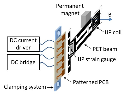
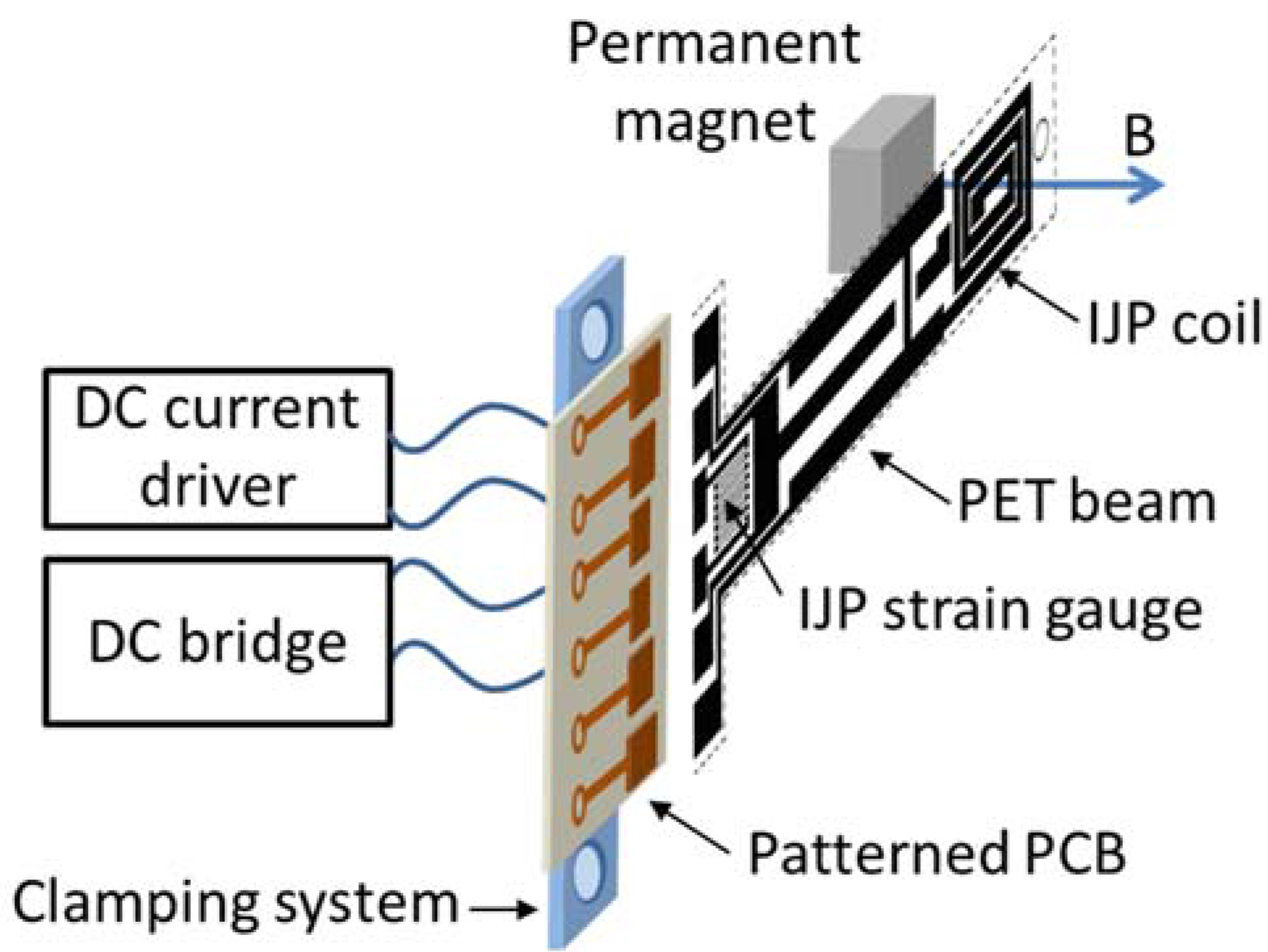
The device schematization is shown in
Figure 1. As it can be observed, the system consists of a conductive coil printed on a flexible beam of PET (poly(ethylene terephthalate) with a thickness of 140 µm) and an external permanent magnet. A DC driving current is forced into the coil. By placing the actuator with the coil perpendicular to the field line, the following force,
FB, is generated:
where
BDC is the magnetic flux density,
Id is the current and θ is the angle between the current and the magnetic field while
K is a constant term which depends on the length of the current pattern. The Lorentz force underpins the deflection mechanism of the beam.
A resistive readout strategy has been also implemented on the beam through an inkjet printed strain gauge. The main task of the printed strain sensor is to monitor the beam deflection also in view of the realization of a closed loop beam positioning system. A dedicated DC bridge based configuration has been used for the sake of signal conditioning.
The printing process adopted to realize both the coil and the resistive sensor on the PET substrate uses a low cost Stylus Office BX535WD piezo inkjet printer (Epson, Suwa, Japan) with a drop volume of 3pl and a metal ink adopted for the realization of conductive patterns. The latter is the silver nano-particles solution “Metalon
® JS-B15P” by Novacentrix (Austin, TX, USA) whose main specifications are given in
Table 1. The adopted PET substrate is the Novele™ IJ-220 Printed Electronics Substrate by Novacentrix, suited to low-cost and low-temperature applications and specifically engineered for inkjet-compatible conductive inks. The thickness of the silver layer on the PET substrate is 200 nm. Main specifications of the substrate are given in
Table 2.
The inkjet printed patterns were dried at room temperature. The long term stability of the electrical properties of the device has been assessed by repeated electrical tests. Future efforts will be dedicated to investigate the effects of thermal sintering on the inkjet printed device.
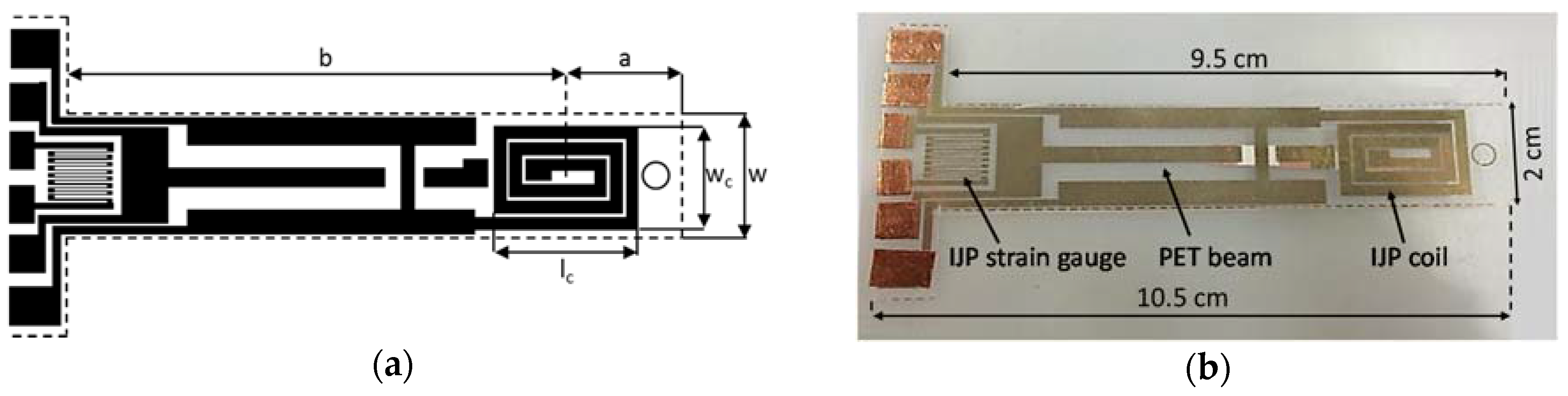
The device beam layout and a real view are shown in
Figure 2a,b, respectively, while the specifications of the printed components are reported in
Table 3. The PET beam is 9.5 cm long and 2 cm wide (see
Figure 2b), while the two dimensions from the clamping to the center of the coil and from the latter to the beam tip,
a and
b in
Figure 2a, are 7.7 cm and 1.8 cm, respectively. The device dimensions have been fixed on the basis of the technology and application driven constraints. In particular, the maximum coil diameter allowed for the positioning application addressed by this work is in the order of 20 mm, while the number of windings are defined by the low-cost inkjet printing equipment adopted, which fixes the minimum track and spacing dimensions to 200 µm and 50 µm, respectively. In the investigated beam the number of windings was
Nw = 3.
In order to investigate the quality of the inkjet printing process which is mainly responsible for the reliability of the electrical device, a morphologic analysis of the printed silver layer has also been performed by electron microscopy (SEM) which evidenced a suitable film uniformity.
In order to implement the electric contact between the beam components and the conditioning electronic the clamping system shown in
Figure 1 was developed. It consists of a sandwich structure clamping the PET substrate and a patterned contacting support realized by Printed Circuit Board (PCB) technology.
Several measurements have been performed to estimate the resistance given by the clamping mechanism at different pressure of clamps. It has been observed that the resistance introduced by the clamping system, for different pressure of clamps, is in the order of few mΩ.
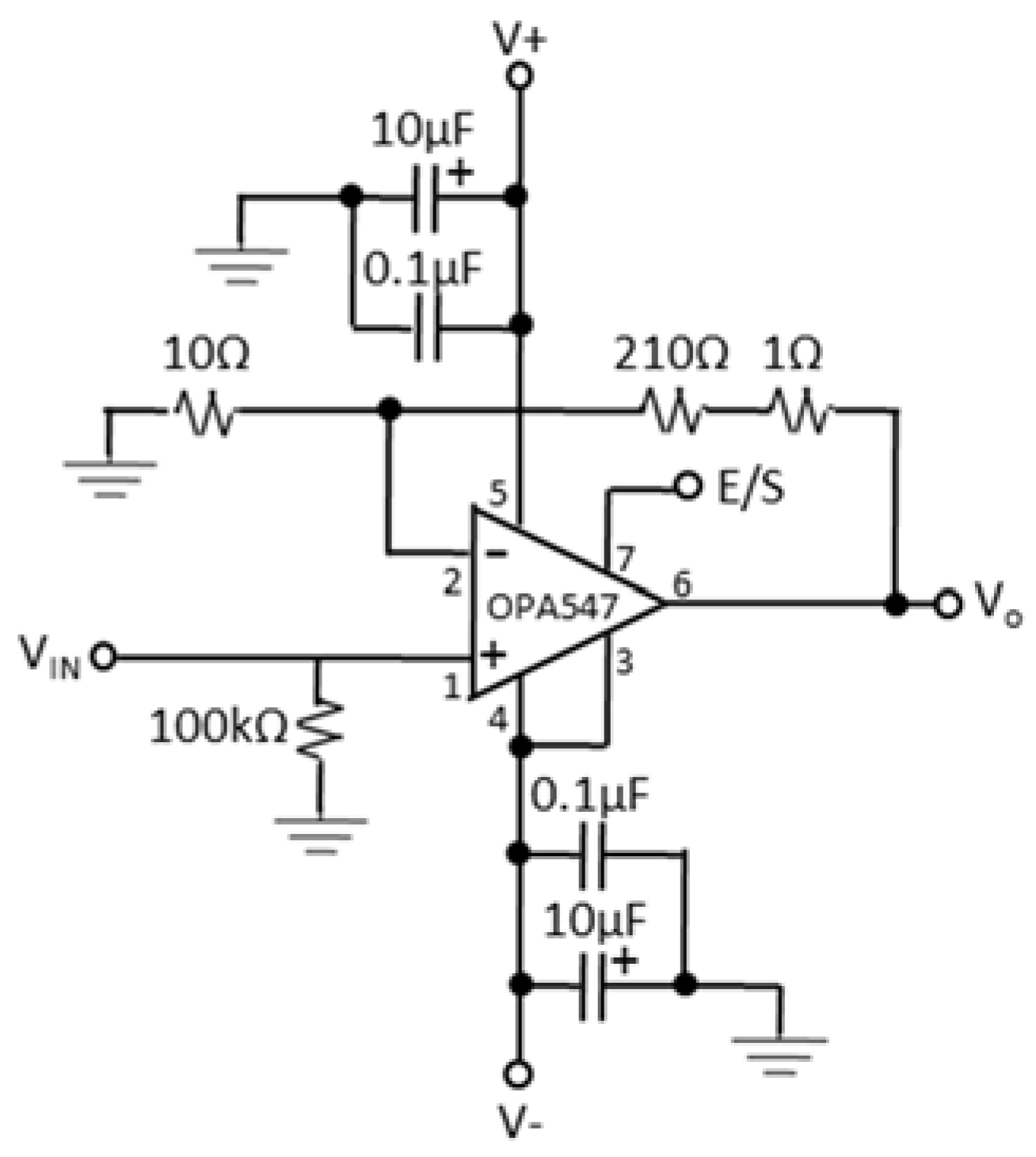
The conditioning electronics consists of the voltage-to-current (V/I) converter shown in
Figure 3 and properly designed to force a current ranging in the interval 10–150 mA with a control voltage in the range 0.1–1.5 V. The power dissipated by the device depends on the driving current and ranges between 0.004 W and 0.9 W.
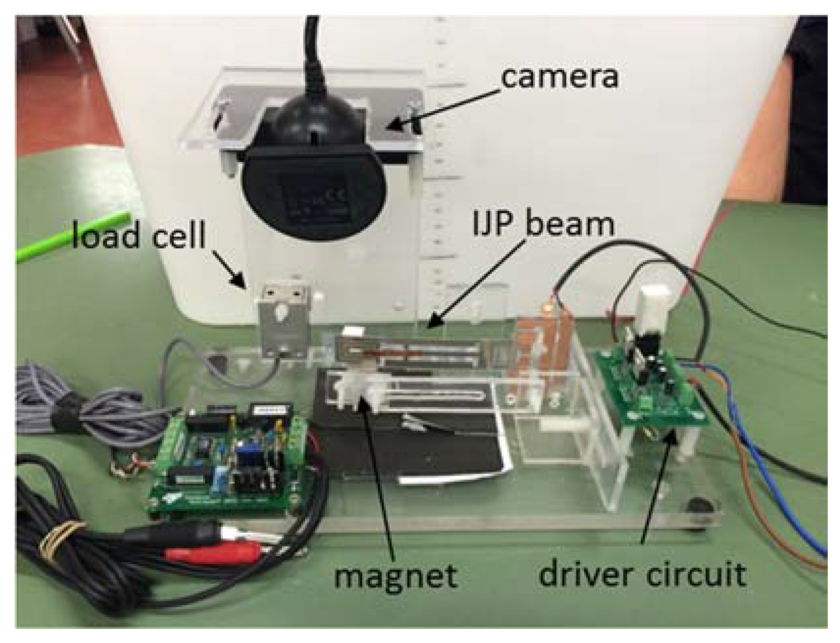
4. Experimental Results
The experimental set-up developed for the sake of the system characterization consists of a PMMA (Polymethyl methacrylate) structure housing the beam, the permanent magnet and the reference sensors. In particular, a calibrated laser distance sensor, model OADM 12U6460/S35A by Baumer (Frauenfeld, Switzerland), has been used to perform an independent measurement of the beam deflection. The set-up is also equipped with the Ps3 EYECam (Sony, Tokyo, Japan) adopted to monitor the beam position and to capture images of the beam bending. The load cell, Transducer Techniques (Temecula, CA, USA) GSO-10, along with the conditioning module Transducer Techniques TMO-1, has been used to measure the blocked force,
FB, exerted by the beam. A photograph of the setup is shown in
Figure 4. Finally, a Hall effect magnetic field sensor, SS496A1 by Honeywell (Morris Plains, NJ, USA), has been used to perform the estimation of the magnetic field induced by the permanent magnet close to the driving coil inkjet printed on the beam. The value of the magnetic field,
BDC, measured in the printed coil as a function of the permanent magnet position, is shown in
Table 4.
A complete characterization survey has been performed to investigate the beam behavior as a function of the driving current, Id, and for different values of the permanent magnetic field, BDC. Actually, it must be considered that the magnetic field has been modulated by changing the distance between the coil and the magnet position. The latter allows for the interpretation of the experimental results as the possibility to control the beam deflection both by the driving current and the position of the external permanent magnet.
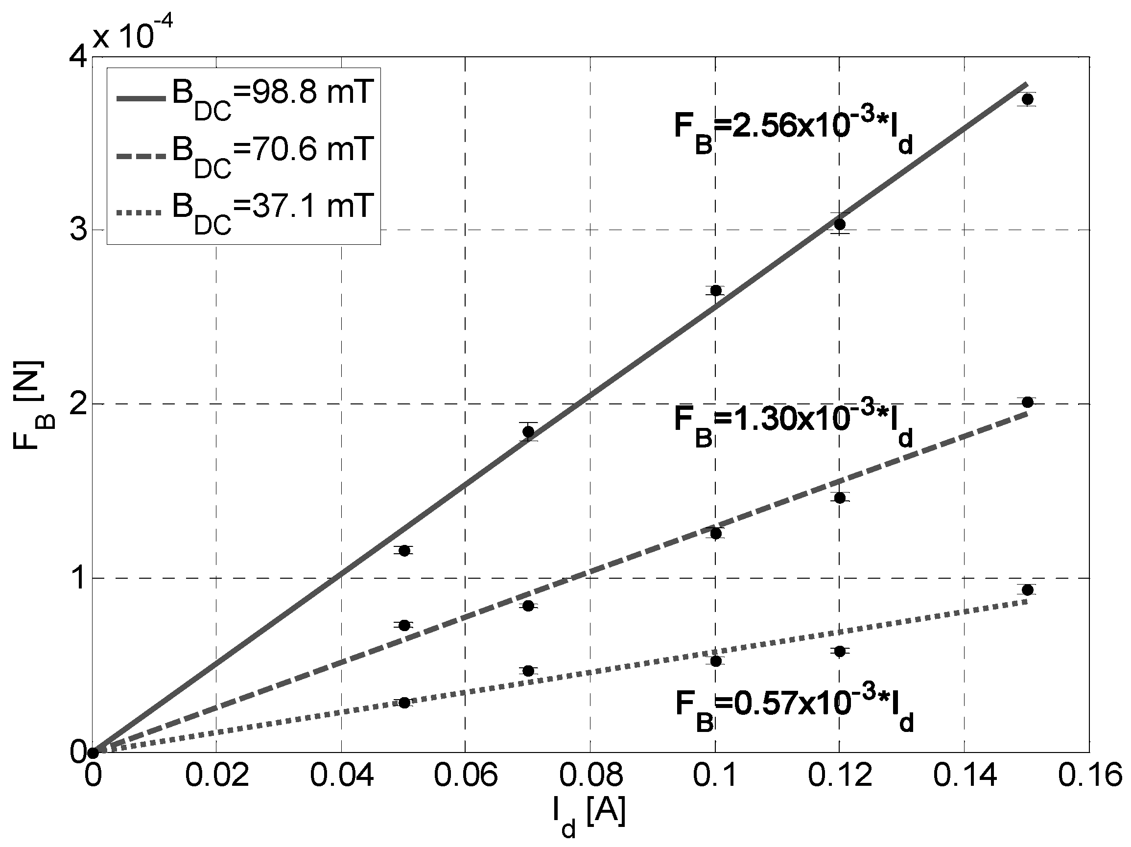
The first set of experiments has been devoted to measure the blocking force of the beam,
FB, by using the load cell. This quantity is of main interest for applications requiring a load handling during the beam deflection. Moreover, such force can be used to perform an indirect measurement of the magnetic force generated by the interaction between the permanent magnet and the driving current.
Figure 5 shows the measured force as a function of
Id for different values of
BDC. The deviation of the experimental data about its mean for each value of
Id is also reported in
Figure 6. As expected, the blocking force increases by increasing the driving current and the magnetic field. A linear model fitting the experimental data is also shown in
Figure 6.
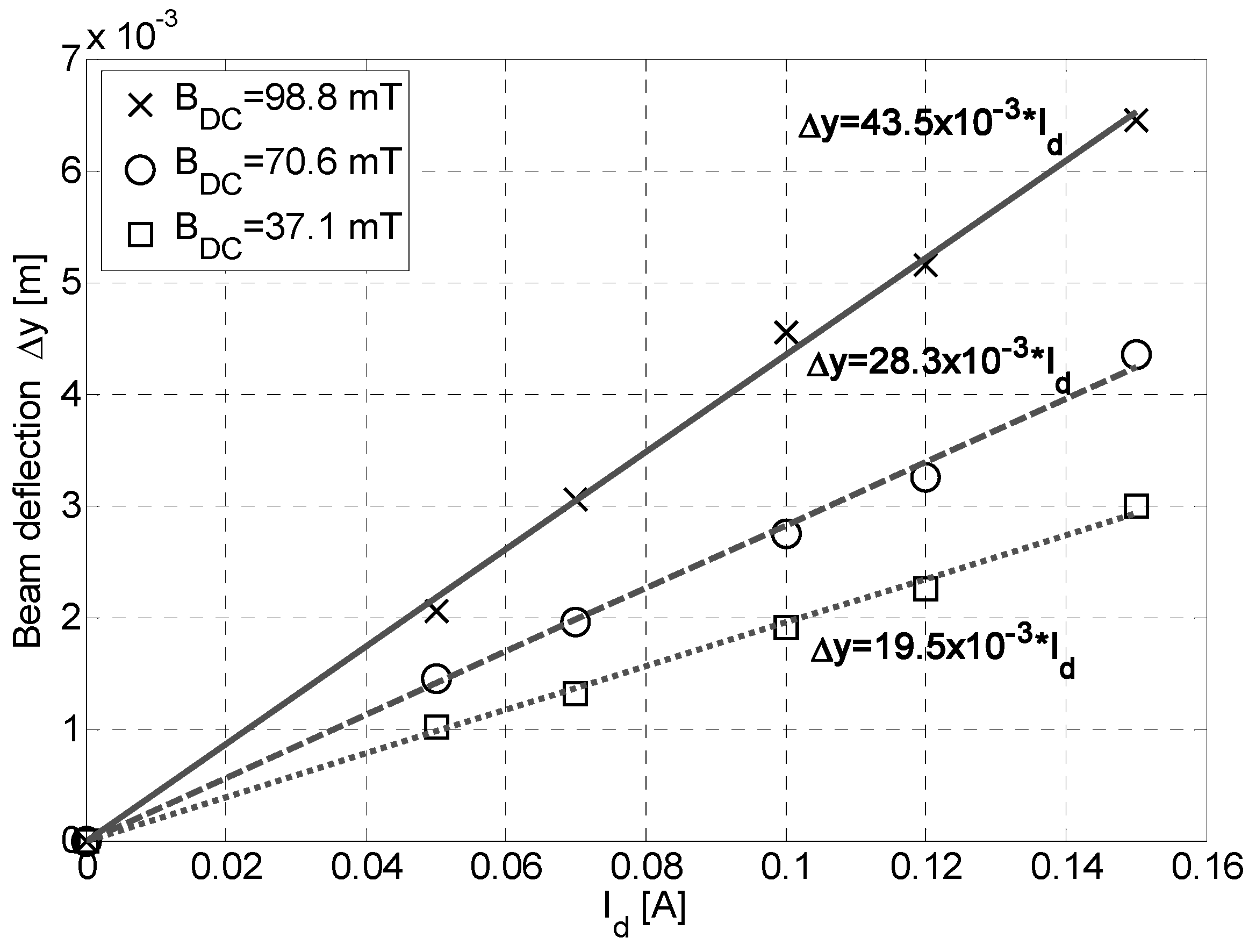
The second investigation was focused on the static beam deflection as a function of the applied magnetic force.
Figure 6 shows the beam deflection, measured by the reference laser, as function of the driving current. The beam deflection increases linearly while increasing the driving current and the magnetic field. The free-end deflection, Δ
y, of a cantilever beam in case of a concentrated load
P at any point is given by [
32]:
where:
= 9.5 × 10⁻² m is the beam length;
1.8 × 10
–2 m is the distance between the coil center and the beam free end (see
Figure 2a);
7.7 × 10
–2 m is the distance between the coil center and the beam blocked end (see
Figure 2a);
× 10–15 m4 is the moment of inertia;
× 10–3 m is the beam thickness;
× 10–2 m is the beam width;
E = 3.5 GPa is the Young’s modulus.
By taking into account Equation (1), model in Equation (2) can be rewritten as it follows:
where the parameter
KB depends on the magnetic field value. Data in
Figure 6 have been interpolated by Equation (3).
The experimental characterization of the device demonstrates an accuracy in the beam positioning in the order of 200 µm.
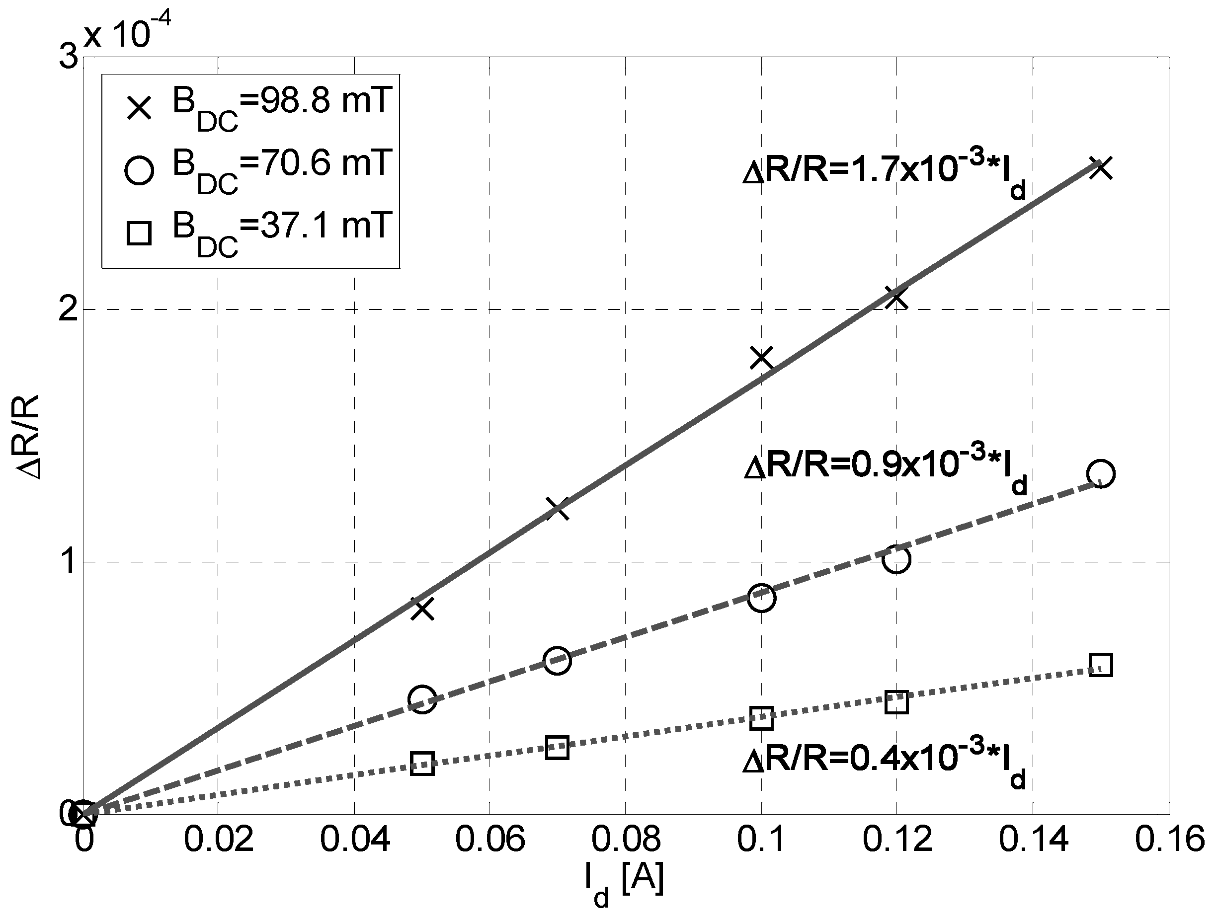
The same results in terms of the fractional change, Δ
R/R, (relative variation) in resistance, of the IJP strain gauge are given in
Figure 7 together with a linear model fitting the experimental data.
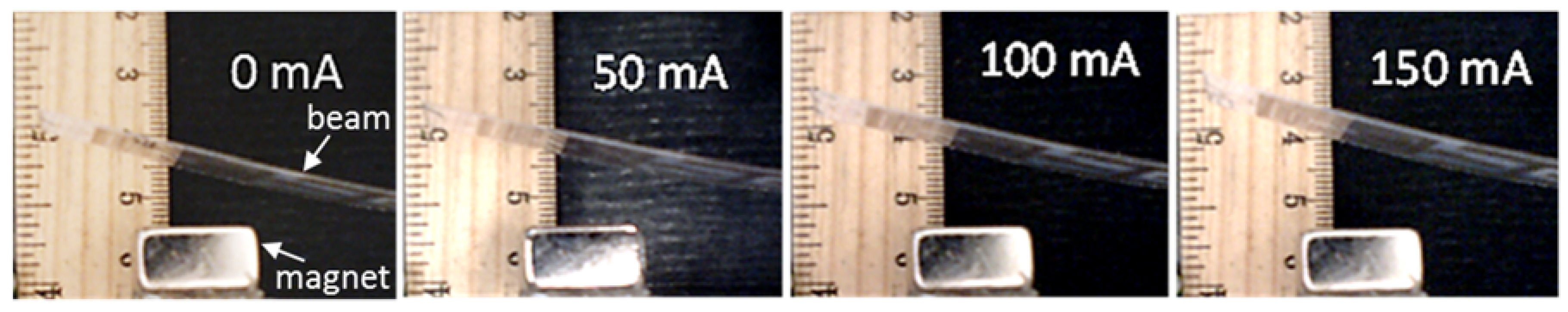
For the sake of completeness, frames acquired by the camera for increasing values of the driving current in the range [0–150] mA in case of a magnetic field of 70.6 mT are shown in
Figure 8.
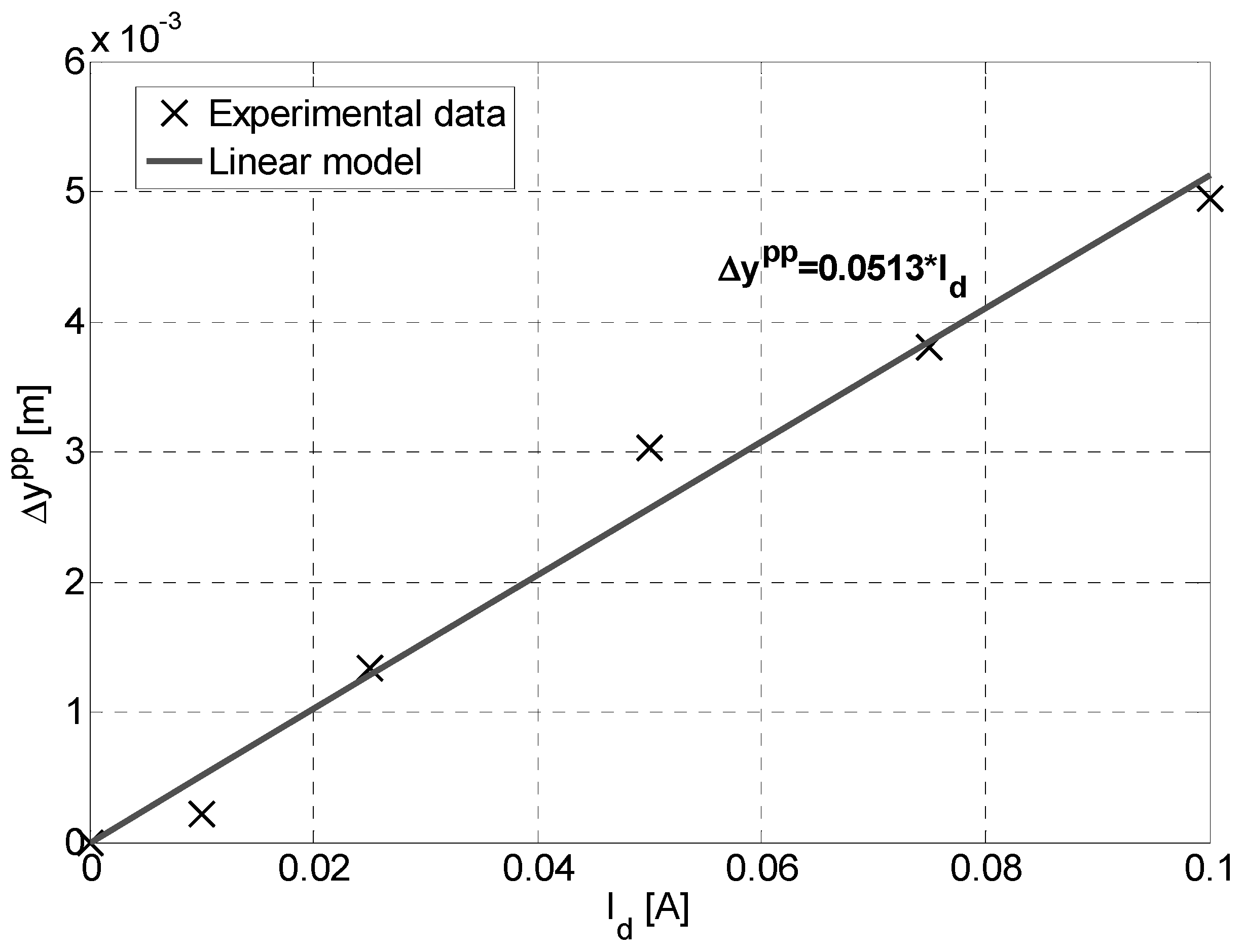
Moreover, the frequency response of the device has been investigated by driving the coil with an AC current spanning the frequency range of interest and a resonance frequency of 4.1 Hz has been observed. The device response in case of sinusoidal driving current at a frequency of 4.1 Hz and
BDC = 37.1 mT is shown in
Figure 9.
5. Conclusions
In summary, in this paper, an electromagnetic driven actuator, fully developed by a low cost Inkjet Printing (IJP) technology is presented. A deep characterization of the device is presented which reveals good performance of the lab-scale prototype developed both in the static and dynamic regime. In particular, the responsivity is found to be a function of the magnetic field used to actuate the beam. The capability of the actuator to produce deflections in the order of few millimeters has been demonstrated experimentally. The device can be suitably applied for positioning applications in the millimeter range with a required loading in the order of hundreds of µN. Specifically, forces in the order up to 375 µN have been measured while responsivities of 43.5 × 10⁻³ m/A, 28.3 × 10⁻³ m/A and 19.5 × 10⁻³ m/A have been estimated in the static condition in case of magnetic fields of 98.8 mT, 70.6 mT and 37.1 mT, respectively. At the resonance frequency of 4.1 Hz, the responsivity is 51 × 10–3 m/A in case of a magnetic field of 37.1 mT.
Future engineered versions of the actuator could be employed as part of the tools for micromachining and in biomedical applications. The actuator is also equipped with an embedded strain sensing feature implemented by an IJP resistive strain sensor. Experimental results demonstrated a linear behavior of the device in terms of displacements as a function of the driving current and magnetic field.
Advantages of the actuation architecture proposed are related to the double position control mechanism (by an external DC magnetic field or a driving current), the embedded strain sensing feature, the layout flexibility and ease with which it adapts to application requirements and the low cost technology and materials adopted.


