Article

Semi-Active Vibration Controllers for Magnetorheological Fluid-Based Systems via Frequency Shaping †

by
Young T. Choi
1,
Norman M. Wereley
1,* and
Gregory J. Hiemenz
2
1
Composites Research Laboratory, Department of Aerospace Engineering, University of Maryland, College Park, MD 20742, USA
2
InnoVital Systems Inc., Calverton, MD 20705, USA
*
Author to whom correspondence should be addressed.
This is a substantially revised version of a paper presented at the ASME Conference on Smart Materials, Adaptive Structures and Intelligent Systems, Snow Bird, Utah, USA, 16–18 September 2013.
Actuators 2025, 14(9), 425; https://doi.org/10.3390/act14090425
Submission received: 2 July 2025 / Revised: 27 August 2025 / Accepted: 28 August 2025 / Published: 30 August 2025

Abstract

This study introduces novel semi-active vibration controllers for magnetorheological (MR) fluid-based vibration control systems, specifically a band-pass frequency-shaped semi-active control (FSSC) and a narrow-band FSSC. These algorithms are designed without requiring an accurate damper model or system identification for control current input. Unlike active controllers, the FSSC algorithms treat the MR damper as a semi-active dissipative device, and their control signal is a control current, not a control force. The performance of both FSSC algorithms is evaluated through simulation using a single-degree-of-freedom (SDOF) MR fluid-based engine mount system. A comparative analysis with the classical semi-active skyhook control demonstrates the advantages of the proposed FSSC algorithms.

1. Introduction

Magnetorheological (MR) dampers and isolators have garnered significant attention in various vibration control applications over the past decade, including engine mounts [1,2], seat suspensions [3,4,5], automotive suspensions [6,7], and vibration isolation tables [8,9]. These MR fluid-based systems are classified as semi-active due to their ability to adjust damping or friction via energy dissipation mechanisms in response to feedback control. This characteristic allows for efficient vibration suppression with low power consumption and inherent stability, unlike active systems that rely on hydraulics or pneumatics. While passive systems that make use of viscoelastic rubber and/or tuned mass dampers are limited to a specific design point, MR fluid-based semi-active control offers robust and effective vibration mitigation across broader frequency ranges, diverse excitation conditions, and variations in payload.
Unlike other semi-active systems utilizing variable orifice, friction, or tuned liquid dampers, MR fluid-based systems enable continuous control of damper forces by simply adjusting the current input to an electromagnet. This adjustment occurs without moving parts, facilitating the implementation of sophisticated semi-active vibration control algorithms.
Traditionally, vibration control algorithms for MR fluid-based semi-active systems have been designed by imposing an energy dissipation constraint on fully active control algorithms such as skyhook, optimal control (e.g., LQR), or sliding mode control. This approach stems from the understanding that semi-active control provides only resistive forces, not external loads, thus typically yielding less effective suppression than fully active methods. Despite the mathematical challenges in directly designing fully semi-active control algorithms, this methodology has been widely adopted and has successfully enhanced the vibration control performance of various MR fluid-based systems.
This study introduces semi-active vibration controllers for MR fluid-based systems: a band-pass frequency-shaped semi-active control (FSSC) and a narrow-band FSSC. These algorithms are uniquely designed without superimposing energy dissipation constraints onto active control frameworks [10], i.e., Choi, Wereley, and Hiemenz (2013). The new FSSC algorithms eliminate the need for accurate damper models or system identification for control current determination. Crucially, the semi-active MR damper is treated as a dissipative device, not an active force producer, during the FSSC algorithm design. The control signal generated by FSSC algorithms is a control current, diverging from the typical control force output of active controllers. Two FSSC algorithms are formulated, and their performance is assessed via simulation using a single-degree-of-freedom (SDOF) MR fluid-based engine mount system. To highlight their advantages, vibration mitigation performance is compared to that of a classical semi-active skyhook control algorithm, commonly used in base excitation problems.

2. Conventional Semi-Active Control

Conventional semi-active control strategies have emerged as a compelling alternative to both passive and fully active vibration control systems, particularly in applications where energy efficiency, reliability, and robustness are paramount. Among various semi-active control algorithms, the skyhook control strategy has been widely adopted due to its simplicity and effectiveness in vibration mitigation.

2.1. Background

A semi-active skyhook controller is implemented in this study to establish the baseline performance of a typical conventional semi-active controller. The skyhook control algorithm, first proposed in 1974 by Karnopp et al. [11], has gained widespread acceptance in semi-active vibration control systems. The fundamental concept involves a hypothetical damper connecting an isolated mass to an inertial reference frame (the “sky”), hence the term “skyhook damper”. This virtual damper generates a force proportional to the absolute velocity of the isolated mass, effectively mitigating vibration. A key advantage of this approach is that the damping force applied to the isolated mass is proportional to the vibration amplitude, and when the mass stops moving, the damper produces no force, ensuring inherent stability of the control algorithm.

2.2. Controller Design

To illustrate the design of a semi-active skyhook control algorithm, we consider an SDOF MR engine mount system in Figure 1. The governing equation of motion for this system is given by
M x ¨ = k c ( x y ) F M R
where F M R represents the damper force of the MR damper, expressed as
F M R = c M R ( x ˙ y ˙ ) + F y sign ( x ˙ y ˙ )
In these equations, x denotes the displacement of the engine mass, y is the excitation displacement input from the floor, M represents the engine mass, k c is the stiffness of the coil spring, and c M R is the damping constant of the MR damper. The MR yield force, F y can be continuously adjusted by applying current to the MR damper according to
F y = α i β
where i is the current input in amperes, where α and β are parameters identified from experimental data, chosen as α = 50 and β = 1.73 for this study. The parameters provided were derived from the design characteristics of a self-powered MR damper in our prior work [12]. Specifically, these values are based on the physical prototype of a self-powered MR damper as detailed in our prior work. This particular damper was designed for applications such as engine mounts within automotive systems. These parameters represent a physical model of an actual MR device, chosen because they are typical design values for such components in automotive applications. Their selection allows for a realistic simulation environment to demonstrate the feasibility and performance of semi-active control strategies in this study. The MR yield force saturates at i m a x = 1.5 A to realistically represent practical device limitations. The system parameters are set to M = 60 kg, k c = 150 kN/m, and c M R = 420 N·s/m, resulting in a resonance frequency of 8 Hz.
In the skyhook control configuration as shown in Figure 2, the skyhook damper force, F s k y , is given by
F s k y = c s k y x ˙
where c s k y is the skyhook damping. Since the MR damper cannot be physically placed between the inertial reference and the isolated mass, it must produce an equivalent force to the skyhook damper. However, being semi-active, the MR damper force direction depends solely on the relative velocity ( x ˙ y ˙ ) . Consequently, the MR damper force matches the skyhook damper force only when the relative velocity has the same sign as the absolute velocity of the mass x ˙ . This condition is expressed as
F s k y × ( x ˙ y ˙ ) 0
This inequality represents the “dissipation condition,” ensuring that the MR damper force remains dissipative. When the relative velocity has a sign opposite to the absolute velocity, the MR damper is turned off (zero current input) to minimize the force magnitude difference due to the opposite direction.
Based on these relationships, the semi-active skyhook control algorithm can be formulated as
F y = c s k y x ˙ if x ˙ ( x ˙ y ˙ ) 0 0 if x ˙ ( x ˙ y ˙ ) < 0
The semi-active skyhook control algorithm, defined in Equation (6), effectively enables the MR damper to dissipate engine mass vibration. It is important to note that the skyhook control force in Equation (6) can be generalized and replaced by a control force derived from any active control algorithm, such as sliding mode control or optimal control. By combining Equations (3) and (6), the control current for the semi-active skyhook control algorithm can be determined as follows:
i = c s k y x ˙ α 1 / β if x ˙ ( x ˙ y ˙ ) 0 0 if x ˙ ( x ˙ y ˙ ) < 0
As seen in Equations (6) and (7), the semi-active skyhook control algorithm requires two sensors to measure the absolute velocity, x ˙ , of the engine mass and also the relative velocity (damper velocity), x ˙ y ˙ .
It should be noted that the MR yield force model given in Equation (3) is commonly used in MR applications because it highlights a key characteristic: the yield force (or torque) is exponentially proportional to the applied current input. This simplified model, which solely relates yield force to current input, does not explicitly account for the complex hysteresis characteristics and the influence of relative velocity on the force-current relationship, which are inherent to all MR dampers. It is crucial to understand that the proposed FSSC algorithms are intentionally designed to circumvent the need for an accurate MR damper model or system identification to determine the control current input. This is a fundamental advantage of our approach. Unlike traditional semi-active control methods that rely on inverse damper models to calculate the control current, the FSSC algorithms directly compute the control current based on frequency-shaped excitation input. Therefore, the specific form of Equation (3) and its limitations regarding hysteresis and relative velocity dependence do not impact the core functionality or performance of the FSSC algorithms. This specific relationship in Equation (3) was used only in the context of the conventional semi-active skyhook control for comparative analysis, as it is a common simplification in such models.

3. Frequency-Shaped Semi-Active Control (FSSC)

Two FSSC vibration controllers are developed in this study: (1) a band-pass FSSC, denoted by BFSSC, and (2) a narrow-band FSSC, denoted by NFSSC.

3.1. Band-Pass FSSC (BFSSC)

The primary concept behind frequency-shaped semi-active control (FSSC) is to apply a larger current input (leading to higher damping) to the MR damper when the dominant frequency of the excitation input is close to the resonance frequency of the isolated vibration system, and to minimize it elsewhere. This is achieved through frequency shaping of the control input. Conversely, when the dominant frequency of the excitation input is greater than the resonance frequency, a smaller or zero current input (low damping) should be applied.
To implement this, it is essential to determine in real-time whether the dominant frequency of the excitation input is indeed close to the resonance frequency of the isolated vibration system. While a Fast Fourier Transform (FFT) could theoretically be employed, it requires at least one period of data to calculate a dominant frequency component in real time. Thus, the FFT is suitable for periodic signals of several periods’ duration or stationary random excitation inputs. However, for transient and non-stationary random excitation inputs, FFT algorithms are less effective due to continuously changing excitation profiles and frequencies. Therefore, in this study, frequency shaping is accomplished via a band-pass filter to ascertain if the dominant frequency of the excitation input is near the vibrating system’s resonance frequency.
When the band-pass filter is tuned to the resonance frequency, ω n , of the vibrating system, the filtered output signal, y band , exhibits maximal magnitude for frequency components near ω n . As the excitation input, y, passes through this filter, the amplitude of y band varies according to the spectral composition of the excitation: For excitation frequencies within the band-pass range ( ω ω n ), the filtered amplitude | y band | closely matches the unfiltered excitation amplitude | y | . Conversely, when excitation frequencies fall outside this range ( ω ω n or ω ω n ), | y band | becomes significantly attenuated relative to | y | .
The BFSSC algorithm exploits this frequency-dependent amplitude modulation by defining the control current, i, as directly proportional to | y band | . This design ensures damping intensifies exclusively during resonant excitation ( ω ω n ), while maintaining minimal damping during non-resonant conditions. Consequently, the approach delivers targeted vibration suppression at critical frequencies while minimizing power consumption and eliminating requirements for complex system identification or force tracking. This frequency-selective control strategy, formalized in Figure 3, is designated as band-pass frequency-shaped semi-active control (BFSSC). The resulting control current input for the BFSSC algorithm is then determined as follows:
i ( t ) = k b y b a n d ( t ) if i ( t ) i m a x i m a x if i ( t ) > i m a x
Here, k b is the control gain of the BFSSC algorithm.
In contrast to conventional semi-active control algorithms [13,14,15,16,17,18,19,20], the BFSSC algorithm does not require the identification of the MR yield force given in Equation (3) because the control current input is directly determined from the magnitude of the filtered displacement excitation input, y b a n d . Additionally, the BFSSC algorithm does not need the dissipation condition of the semi-active skyhook control algorithm given in Equation (5). Consequently, the BFSSC algorithm given in Equation (8) requires only one sensor to measure the excitation input, y, while the semi-active skyhook control algorithm needs two sensors to measure the absolute velocity of the engine mass but also the relative velocity as shown in Equation (7).
In this study, a second-order Butterworth digital filter was utilized for the band-pass filter, and its transfer function is
H ( z ) = b 0 + b 1 z 1 + b 2 z 2 + b 3 z 3 + b 4 z 4 1 + a 1 z 1 + a 2 z 2 + a 3 z 3 + a 4 z 4
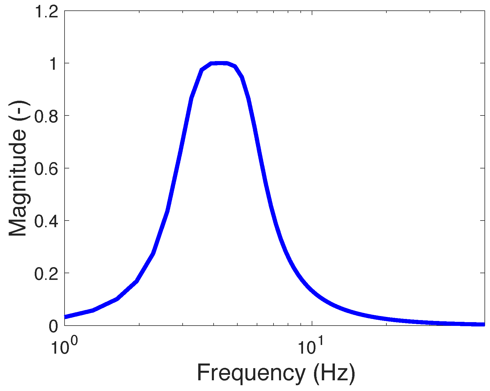
Here, z is the z-transform operator, and a i and b i are the band-pass filter coefficients. The frequency response of the band-pass filter is depicted in Figure 4, where the passband is set between 3 and 6 Hz. When the excitation signal falls within this frequency range, the controllable damping is maximized, effectively targeting resonant vibrations. Conversely, for excitation frequencies outside the passband, the controllable damping is minimized. It is important to note that while a Butterworth digital filter is employed in this study, alternative filter designs may be utilized as appropriate for different application requirements. On the other hand, the passband was intentionally set between 3–6 Hz, for the consideration that the natural frequency of the isolated engine mount system is 8 Hz because this bandwidth functions as a control parameter specifically tuned for this particular engine mount system and its simulated operating conditions. The primary reason for setting this specific band for this system is to ensure that less control current is applied after the crossover frequency (i.e., beyond the resonance region). This design philosophy aims to optimize the control effort by concentrating damping primarily at or leading up to the resonance, and then reducing control activity at higher frequencies where the system may inherently provide sufficient isolation, or where excessive damping could be counterproductive or consume unnecessary power. It is crucial to emphasize that this bandwidth, being a control parameter, is system-specific. For different vibration systems or varying operating conditions, the optimal bandwidth of the filter may need to be re-tuned or adjusted accordingly to align with that system’s specific resonance frequencies or desired control objectives.
The band-pass filter equation corresponding to Equation (9) is given as follows:
y b a n d ( n ) = b 0 y ( n ) + b 1 y ( n 1 ) + b 2 y ( n 2 ) + b 3 y ( n 3 ) + b 4 y ( n 4 ) a 1 y b a n d ( n 1 ) a 2 y b a n d ( n 2 ) a 3 y b a n d ( n 3 ) a 4 y b a n d ( n 4 )
Here, n denotes the discrete time index, with y band ( n ) representing the filtered displacement excitation input at time step, n, and y ( n ) indicating the original displacement excitation input at the same time step. Based on Equation (10), the resulting control current input, i ( n ) , for the BFSSC algorithm can be expressed as follows:
i ( n ) = k b y b a n d ( n ) if i ( n ) i m a x i m a x if i ( n ) > i m a x
It should be noted that the Butterworth digital filter used in this study was designed to have a flat frequency response in its passband, which helps in minimizing phase distortion within the desired frequency range (3–6 Hz in this study). While any real-time filter will introduce some phase shift, for vibration control applications where the primary objective is amplitude attenuation at resonance, a constant phase lag across the relevant frequency band is generally acceptable and does not negatively impact the control objective. The critical aspect is to ensure that the phase relationship between the filtered signal and the system’s dynamics remains consistent, allowing the control current to be applied effectively during resonant conditions. In this study, the band-pass filter is applied to the excitation input (y) to identify when the system is experiencing resonance. The control current is then applied proportionally. For the proposed FSSC algorithms, the amplitude of the excitation input is more critical than its phase for accurately detecting resonant conditions. On the other hand, the computational load associated with the second-order Butterworth digital filter is minimal, involving a relatively small number of arithmetic operations (multiplications and additions) per time step, as demonstrated in Equation (10). This makes it highly suitable for real-time implementation. Modern microcontrollers, commonly employed in engineering applications, are fully capable of handling these computations efficiently, even for a rapid sampling period of 0.5 ms. The filter’s second-order simplicity ensures that the computational demand remains manageable for practical deployment.
On the other hand, while directly measuring “excitation displacement” (e.g., road profile) can be challenging in some real-world scenarios, our choice to use excitation displacement as the input for the FSSC algorithms in this simulation study was deliberate for an engine mount system. For engine mounts, the “excitation” typically comes from the engine block itself (which is the isolated mass) or the vehicle chassis/floor on which the mount is situated. In many automotive applications, the excitation input from the chassis or floor can be reliably measured using accelerometer sensors placed on the vehicle’s frame or directly on the component generating the vibration. For example, in the context of an engine mount, measuring the vibration of the “floor” (vehicle chassis) is often feasible. Furthermore, it’s important to note that the FSSC algorithms require only the magnitude of the filtered excitation displacement (or its proxy) to determine the control current. This means that if direct displacement is difficult to obtain, other measurable quantities that are proportional to the excitation (like acceleration, which is often easier to measure) at an easily accessible location could potentially be integrated with appropriate filtering or integration techniques to derive a signal suitable for frequency shaping. This would require further research into appropriate signal processing and sensor fusion. However, for the scope of this paper, which focuses on the theoretical development and simulation of frequency-shaped semi-active controllers for MR fluid-based systems, using the excitation displacement as input for simulation purposes is a valid starting point to demonstrate the core concept of frequency shaping based on the source of excitation rather than the response of the isolated mass.

3.2. Narrow-Band FSSC (NFSSC)

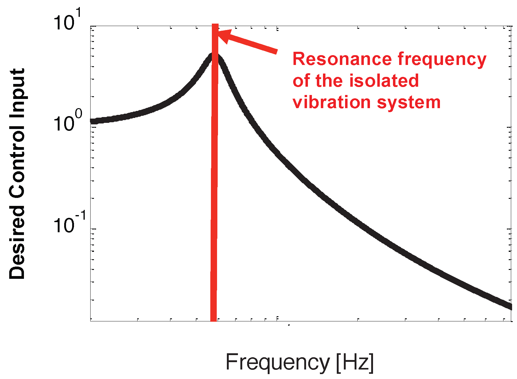
As explained earlier, the control input should be strongest near the isolated system’s resonance frequency. However, if this resonance frequency exceeds the crossover point, the control input should be reduced. Figure 5 illustrates this desired frequency shaping for the control current input. In this case, this desired frequency shaping of the control input can be precisely matched to the frequency response of an SDOF vibration isolation system. The relationship is defined as follows [21]:
y out ( ω ) y ( ω ) = 1 + 4 ζ n a 2 ω 2 ω n a 2 1 ω 2 ω n a 2 2 + 4 ζ n a 2 ω 2 ω n a 2
Here, ω represents the frequency, while ω n a and ζ n a are the resonance frequency and damping ratio of the SDOF system, respectively. y out denotes the output displacement of the SDOF vibration isolation system when subjected to an excitation displacement input, y. Notably, the resonance frequency, ω n a , of this isolation system will be set close to ω n , the resonance frequency of the MR engine mount system.
The governing equation for the SDOF vibration isolation system, from Equation (12), is
y ¨ out ( t ) = ω n a 2 y out ( t ) y ( t ) 2 ζ n a ω n a y ˙ out ( t ) y ˙ ( t )
As illustrated in Figure 5, the output displacement y out ( t ) exhibits a pronounced increase near the resonance frequency ω n of the MR engine mount system. By setting the control current input to be proportional to the amplitude of y out ( t ) , the resulting current input becomes significantly larger only within a narrow frequency band centered around the resonance of the SDOF vibration isolation system described by Equation (12). This semi-active control approach is referred to as narrow-band frequency-shaped semi-active control (NFSSC).
The control current input for the NFSSC algorithm is determined by
i ( t ) = k n | y out ( t ) | if i i max i max if i > i max
Here, k n is the control gain for the NFSSC algorithm. In order to compute the control input from Equation (14) in real time, it is necessary to simultaneously solve Equation (13) in real time as well. To facilitate practical implementation, Equation (13) was discretized using the Euler method:
y n o u t ( n ) = 2 2 ζ n a ω n a h y o u t ( n 1 ) 1 + ω n a 2 h 2 2 ζ n a ω n a h y o u t ( n 2 ) + 2 ζ n a ω n a h y ( n 1 ) + ω n a 2 h 2 2 ζ n a ω n a h y ( n 2 )
Here, h denotes the calculation time step, which was set to 0.5 ms in this study. Utilizing Equation (15), the final control current input, i ( n ) , for the NFSSC algorithm is given by
i ( n ) = k n | y out ( n ) | if i ( n ) i max i max if i ( n ) > i max
It should be emphasized that both the NFSSC and BFSSC algorithms are similar in that they both require only a single sensor to measure the input excitation, denoted as y. This is evident in the fact that the NFSSC algorithm, as stated in Equation (16), and the BFSSC algorithm, as stated in Equation (11), share this fundamental requirement for their operation.

4. Simulation Results

4.1. Steady-State Responses in the Frequency Domain

To assess the vibration control efficacy of the BFSSC and NFSSC algorithms, we first conducted simulations of the MR engine mount system’s controlled response under sinusoidal excitation. Typical excitation levels for engine mount systems range from a strong ± 1.0 mm amplitude to a mild ± 0.1 mm amplitude [22,23,24,25]. Consequently, these amplitudes were selected as the excitation input amplitudes for our simulation study. Furthermore, to account for the inherent time delay in MR dampers, a time constant of 5 ms was adopted for the MR damper model.

4.1.1. Performance Under Strong Excitation (±1.0 mm)

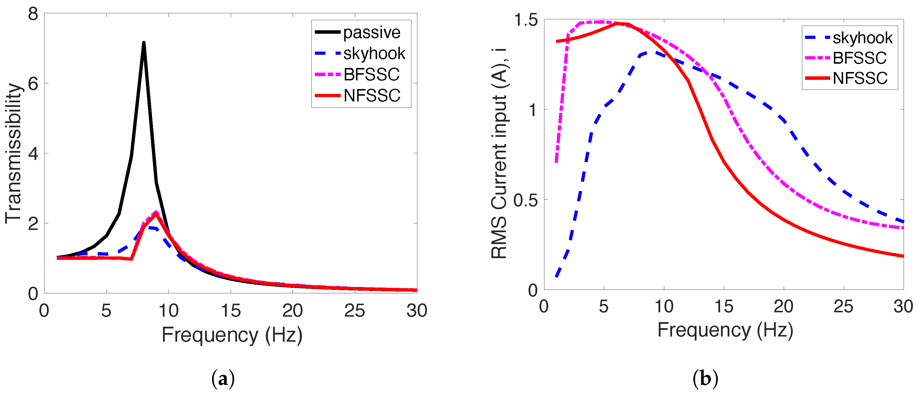
Figure 6 presents the simulated steady-state frequency responses of the MR engine mount system under the various control strategies, when subjected to a constant sinusoidal excitation input of ± 1.0 mm . In these simulations, the displacement amplitude was maintained at 1.0 mm , and the excitation frequency was incrementally swept from 1 to 30 Hz . The term “passive” denotes the MR damper operating in its passive state with zero current input ( 0 A ). The “skyhook” configuration refers to the semi-active skyhook control strategy with a control gain of c s k y = 2200 . “BFSSC” and “NFSSC” correspond to the band-pass and narrow-band FSSC algorithms, with control gains of k b = 32,000 and k n = 4000 , respectively. These gains were held constant throughout all simulation scenarios in this study.
The results depicted in Figure 6 indicate that all semi-active control algorithms provide substantial vibration attenuation across the examined frequency range. The difference in performance between the BFSSC and NFSSC algorithms is minimal. As illustrated in Figure 6b, the control current inputs for the BFSSC, NFSSC, and skyhook algorithms all increase notably near the resonance frequency of the MR engine mount system, and then decrease at frequencies above resonance.
A practical distinction among the control strategies is that the semi-active skyhook approach requires two sensors to measure both the relative and absolute velocities of the engine mass. In contrast, the BFSSC and NFSSC algorithms necessitate only a single sensor to measure the base excitation of the floor, as detailed in Figure 2. This reduction in sensor requirements directly translates to lower hardware costs, simpler system integration, and enhanced reliability in practical engineering applications. This simplification in sensor architecture is a substantial practical advantage.

4.1.2. Performance Under Mild Excitation (±0.1 mm)

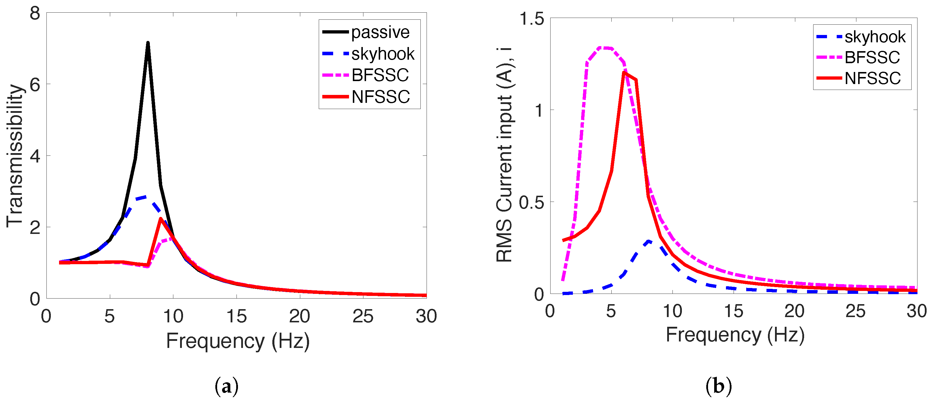
Figure 7 displays the simulated steady-state frequency responses of the controlled engine mount systems subjected to a constant sinusoidal excitation input of ± 0.1 mm . The results indicate that all of the semi-active control algorithms maintain effective vibration attenuation, regardless of the reduced excitation amplitude. Notably, the BFSSC and NFSSC algorithms demonstrate a lower sensitivity to changes in excitation amplitude when compared to the semi-active skyhook control, thereby providing more consistent vibration control performance. Furthermore, as illustrated in Figure 7b, the control current input for the skyhook algorithm is significantly lower for the 0.1 mm excitation case compared to the 1.0 mm scenario. In contrast, the control current inputs for the BFSSC and NFSSC algorithms are not significantly reduced, demonstrating their design to maintain a consistent control effort even with lower excitation amplitudes. Despite the reduced current for skyhook and the relatively constant current for FSSC, all algorithms effectively modulate the damping to suppress vibrations, with the current for both excitation amplitudes peaking in the vicinity of the resonance frequency before decreasing at higher frequencies. This demonstrates the effectiveness of the FSSC algorithms across different operating conditions.

4.2. Transient Responses for MR Damper with 5 ms Time Constant

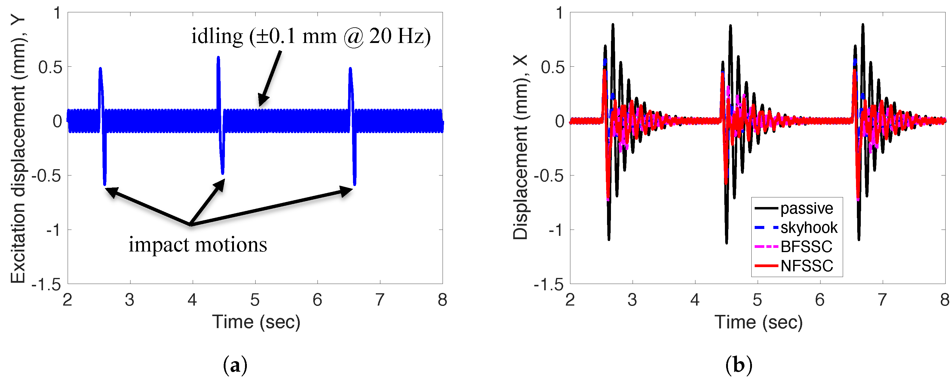
Engine mount systems are primarily designed to attenuate engine-induced vibrations in automobiles, particularly during idling conditions. Under these circumstances, excitation levels are typically low (±0.1 mm), with the dominant excitation frequency generally centered around 20 Hz. However, engine mount systems may also be subjected to significant impact inputs during events such as uneven firing, abrupt acceleration or deceleration, braking, and cornering [23,26,27]. To comprehensively assess the performance of controlled MR engine mount systems, this study analytically investigated their time-domain responses under a simulated representative transient input, which comprised a combination of a sinusoidal excitation of ± 0.1 mm at 20 Hz and intermittent impact motions.
As shown in Figure 8, all semi-active control algorithms outperformed the passive system in terms of transient vibration suppression. In particular, the implemented control strategies enabled rapid attenuation of engine mass displacement following strong impact inputs.
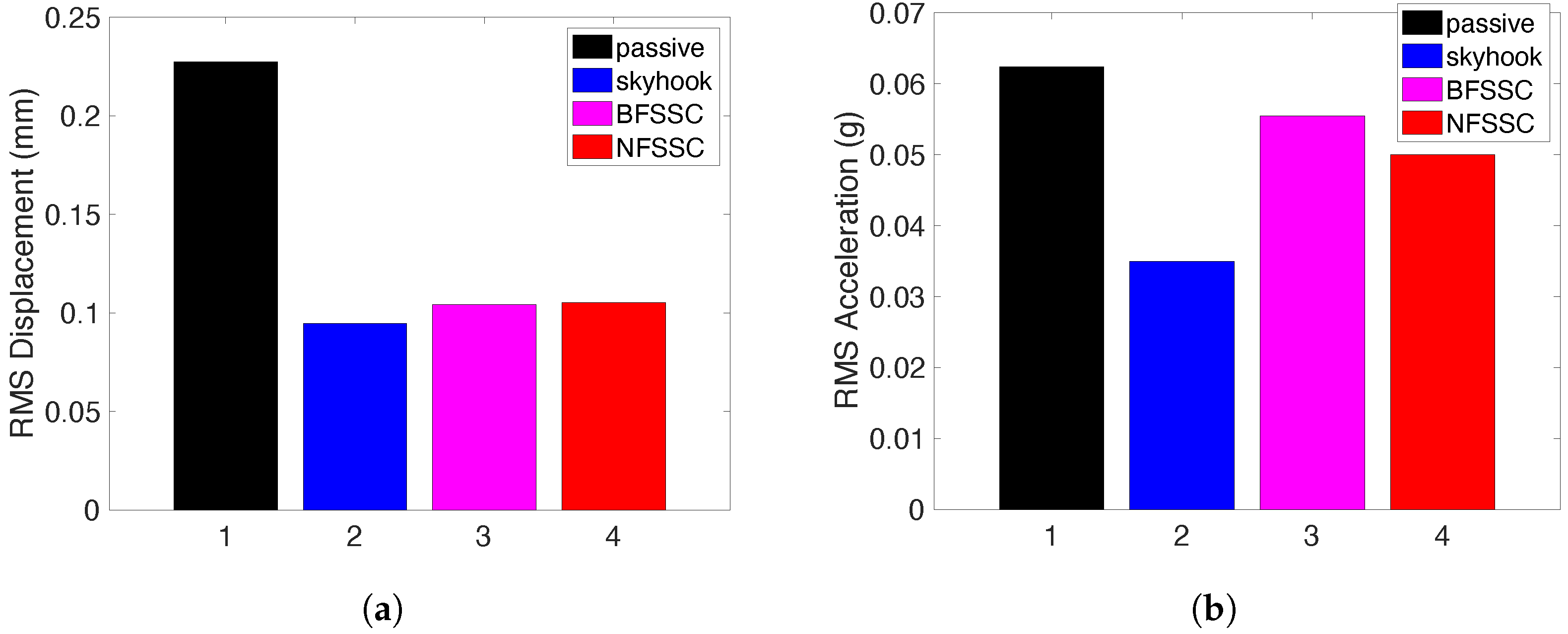
Figure 9 provides a bar chart comparison of the controlled engine mount systems under the representative excitation scenario. As illustrated in Figure 9b, the root-mean-square (RMS) displacements of the engine mass were significantly reduced for all semi-active control algorithms relative to the passive case. Both the BFSSC and NFSSC algorithms achieved reductions in engine displacement comparable to that of the semi-active skyhook control. However, in terms of engine acceleration reduction, while the BFSSC and NFSSC algorithms outperformed the passive system, their performance was inferior to that of the semi-active skyhook control.
It should be noted that the primary focus of the developed FSSC algorithms in this study was on vibration isolation, particularly at the resonance frequency, aiming to reduce transmissibility and, hence, isolate the engine mass from the base excitation. The observation that skyhook control yields better acceleration reduction is consistent with its direct control strategy, which often aims to minimize absolute velocity or acceleration, depending on the specific implementation of the skyhook damping coefficient. The FSSC algorithms, by focusing on frequency shaping of the excitation input, inherently prioritize damping at specific frequencies rather than directly minimizing absolute acceleration across all conditions. Incorporating acceleration feedback, perhaps through a hybrid control strategy or a more advanced FSSC formulation, could potentially lead to a greater reduction in acceleration response. However, this may come at the cost of increased sensor requirements (an additional accelerometer may be needed on the isolated mass) and potentially increased computational complexity, moving away from the simplified single-sensor architecture that is a key advantage of the current FSSC design. The current FSSC design in this study explicitly avoids sensing the response of the isolated mass to maintain simplicity.
On the other hand, while the frequency-domain transmissibility plots (Figure 6 and Figure 7) show comparable performance between FSSC and skyhook under the steady-state sinusoidal excitations, the FSSC algorithms exhibit robustness by not requiring an inverse damper model or system identification. This inherent simplicity in the control logic, coupled with comparable displacement reduction, particularly under transient excitation (Figure 8 and Figure 9), demonstrates that the FSSC provides an effective solution without the complexities of traditional model-dependent or multi-sensor approaches. The marginal difference in performance in some scenarios underscores the core achievement: comparable performance to a more complex, sensor-intensive skyhook control algorithm is delivered, but with a simpler and more cost-effective implementation.

4.3. Responses for MR Damper with 20 ms Time Constant

The time constant of the MR damper is a key dynamic characteristic that significantly influences its performance and the overall effectiveness of semi-active control strategies. In the current simulation study, the MR damper has been modeled as a relatively fast response actuator, assuming a time constant of approximately 5 ms. This value is representative of well-designed MR dampers that are capable of rapid adjustments in their damping properties, enabling precise and timely vibration mitigation. A short time constant ensures that the damper can effectively and quickly track the desired control current and apply the necessary damping force, which is particularly critical for controlling vibrations across a range of frequencies and during transient events.
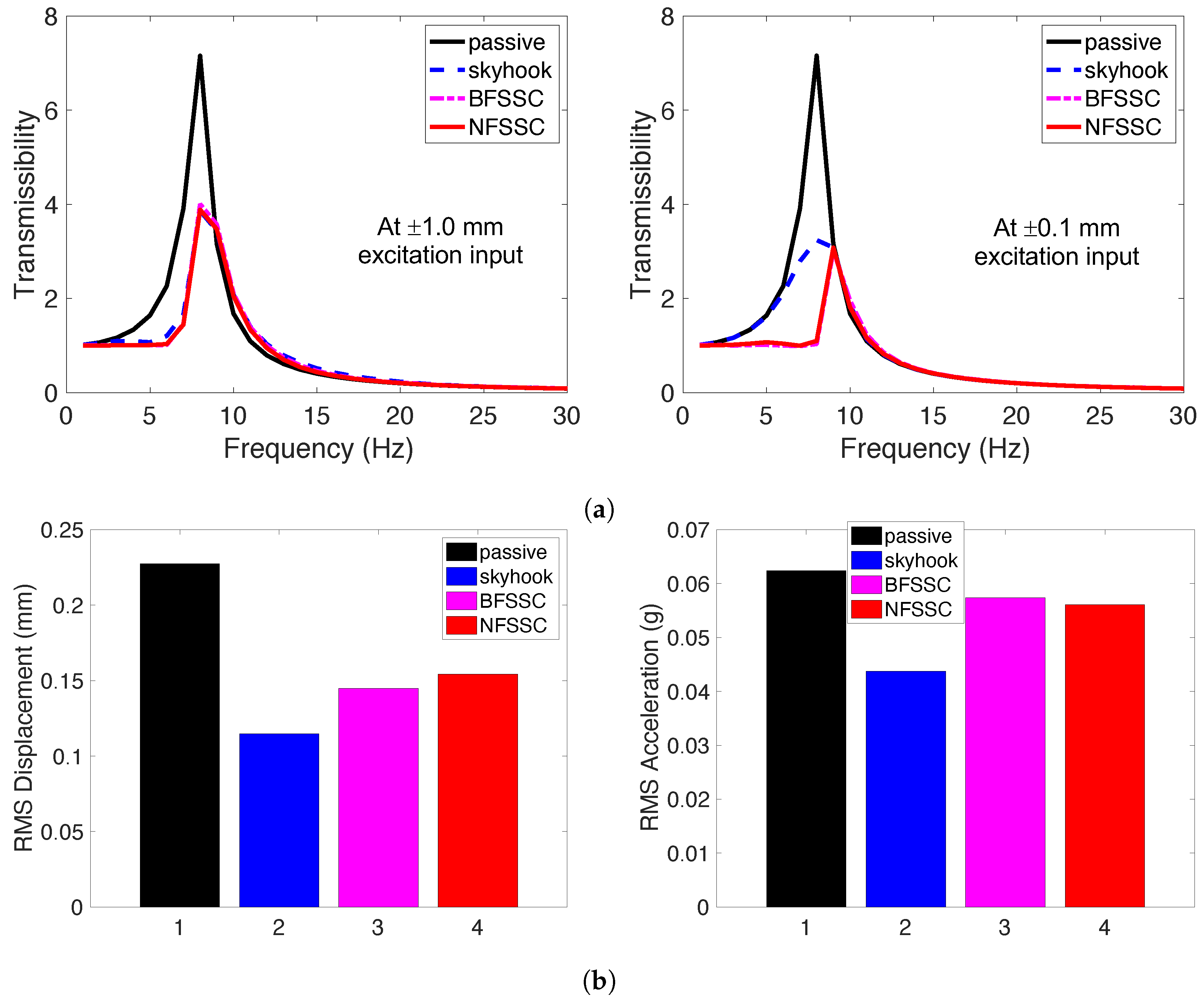
A significantly slower damper response, such as for a damper with a time constant of 20–25 ms, would introduce a notable delay between the control command issued by the FSSC algorithms and the actual change in the damper’s force output. This increased lag would inevitably influence the obtained results, leading to a reduced effectiveness where the damper might not apply the optimal damping force at the precise moment needed. Furthermore, a substantial delay could cause a phase mismatch between the desired control action and the actual damper response, potentially making the control less efficient or even counterproductive. Slower dampers inherently have a more limited operational bandwidth, making them less effective at controlling higher frequency vibrations, including those around the 8 Hz resonance of the system in this study. For a direct comparison of the FSSC concept against a much slower system, the simulated responses of the MR engine mount systems with a time constant of 20 ms are presented in Figure 10.
As anticipated, all controlled performances under the much slower system are less effective than those under the faster system. First, regarding steady-state performance shown in Figure 10a, at ±1.0 mm excitation input, the peak transmissibility of the passive system remains the same, but the controlled systems (skyhook, BFSSC, NFSSC) show a reduced steady-state vibration isolation performance compared to the faster damper (see Figure 6a). The transmissibility plots for the controlled systems are notably higher than those seen with the 5 ms time constant, indicating that the slower response time hinders their ability to suppress the resonant peak effectively. The curves are also slightly broader, suggesting a less precise control action. Nevertheless, the skyhook and FSSC algorithms still manage to reduce the peak transmissibility significantly compared to the passive case. A similar trend is observed at ±0.1 mm excitation input, where the peak transmissibility values for the controlled systems are slightly higher than those of the faster damper (see Figure 7a). It is notable, however, that the deterioration in performance for the controlled cases is less pronounced at the lower excitation input compared to the higher excitation input. This suggests that the impact of the slower time constant is more significant when the required control forces are larger, as is the case with higher amplitude excitation. Second, the transient performance shown in Figure 10b, confirms the reduced performance of all control strategies with the slower damper. The bar charts for RMS displacement and RMS acceleration show that values for skyhook, BFSSC, and NFSSC are all higher than those obtained with the 5 ms time constant (see Figure 9). Despite this, the control algorithms remain effective at mitigating transient vibrations, demonstrating their continued benefit even with the limitations of a slower-response damper.

5. Conclusions

This study developed and evaluated novel semi-active vibration control algorithms for magnetorheological (MR) fluid-based systems, analytically assessing their vibration control performance on a single-degree-of-freedom (SDOF) MR engine mount system. Our proposed algorithms utilize frequency shaping for the control input. This design ensures that damping effort is concentrated on mitigating the engine mount’s resonance, while minimizing damping above the crossover frequency. This approach marks a significant departure from conventional semi-active controls, which typically superimpose an energy dissipation condition on the control algorithm.
We formulated two distinct frequency-shaped semi-active control (FSSC) algorithms, each employing a different frequency-shaping method. The first, band-pass filter semi-active control (BFSSC), uses a band-pass filter centered approximately at the resonance frequency. The second, narrow-band frequency-shaping semi-active control (NFSSC), leverages a transfer function representing the dynamics of an SDOF vibration isolation system. For comparison, we also developed a typical semi-active skyhook control algorithm.
Simulation results demonstrated that both BFSSC and NFSSC deliver vibration attenuation performance comparable to the widely used semi-active skyhook controller under sinusoidal excitation. Importantly, the FSSC algorithms exhibited reduced sensitivity to variations in excitation amplitude, ensuring consistent vibration control across a range of operating conditions. Under transient excitation scenarios, including combined mild sinusoidal and impact inputs, both BFSSC and NFSSC provided robust transient vibration suppression, with engine displacement reduction performance on par with the skyhook controller. However, the skyhook algorithm remained superior in reducing engine acceleration. This is a key trade-off for the simplified FSSC control designs focusing on vibration isolation at resonance. Although a longer damper time response (20 ms) reduced overall effectiveness, the FSSC algorithms still provided good performance improvement in engine displacement reduction, demonstrating their robustness to this dynamic characteristic. A key practical advantage of the BFSSC and NFSSC algorithms is simplicity for an SDOF implementation: only one sensor is required for the measurement of base excitation, and it does not depend on detailed models of the plant or MR damper. In contrast, skyhook control and other advanced semi-active strategies for SDOF implementations require at least two sensors and accurate dynamic modeling, which increases system complexity.
In summary, these frequency-shaped semi-active control algorithms offer an effective and easily implementable alternative for vibration mitigation in MR-based systems, with strong potential for practical automotive applications.
Future work could focus on experimental validation and the extension of these algorithms to multi-degree-of-freedom and non-linear systems. The possibilities for experimental validation include fabricating a physical prototype of the MR damper, constructing an SDOF test rig to mimic the engine mount system dynamics, utilizing shaker tables for realistic excitation inputs, and implementing the FSSC algorithms on a real-time control hardware platform for high-speed data acquisition and control. However, several limitations and challenges are anticipated in implementing experimental validations. These include the precision required in damper manufacturing, ensuring accurate excitation measurement, and accounting for the inherent non-linearities and hysteresis of real MR dampers not fully captured in simplified models. On the other hand, another future work could investigate a hybrid control strategy or a more advanced FSSC formulation that incorporates acceleration feedback to achieve a greater reduction in acceleration response.

Author Contributions

Conceptualization, Y.T.C., N.M.W. and G.J.H.; methodology, Y.T.C. and N.M.W.; software, Y.T.C.; validation, Y.T.C. and N.M.W.; formal analysis, Y.T.C. and N.M.W.; investigation, Y.T.C.; resources, N.M.W. and G.J.H.; data curation, Y.T.C.; writing—original draft preparation, Y.T.C.; writing—review and editing, Y.T.C., N.M.W. and G.J.H.; visualization, Y.T.C.; supervision, G.J.H.; project administration, G.J.H.; funding acquisition, G.J.H. All authors have read and agreed to the published version of the manuscript.

Funding

This research was funded under a Phase 2 SBIR project from the US Army.

Data Availability Statement

Data used in this study is available upon reasonable request.

Conflicts of Interest

The authors declare no conflicts of interest. The funders had a role neither in the design of the study; in the collection, analyses, or interpretation of data; in the writing of the manuscript; nor in the decision to publish the results. Dr. Hiemenz is employed by InnoVital Systems Inc. The remaining authors declare that the research was conducted in the absence of any commercial or financial relationships that could be construed as a potential conflict of interest.

Abbreviations

The following abbreviations are used in this manuscript:
BFSSCBand-pass Frequency Shaped Semi-Active Control
FFTFast Fourier Transform
FSSCFrequency Shaped Semi-Active Control
LQRLinear Quadratic Regulator
MRMagnetorheological
NFSSCNarrow-band Frequency Shaped Semi-Active Control
SDOFSingle-degree of Freedom
RMSRoot Mean Square

References

  1. Jin, Z.; Yang, F.; Rui, X.; Jiang, M.; Wang, J. Design, Modeling, and Vibration Control of a Damper Based on Magnetorheological Fluid and Elastomer. Actuators 2024, 13, 241. [Google Scholar] [CrossRef]
  2. Yang, J.; Ezani, S.; Gong, N.; Deng, L.; Zhang, S.; Li, W. New Magnetorheological Engine Mount with Controllable Stiffness Characteristics Towards Improved Driving Stability and Ride Comfort. Smart Mater. Struct. 2022, 31, 125009. [Google Scholar] [CrossRef]
  3. Choi, Y.T.; Wereley, N.M.; Hiemenz, G.J. Three-Axis Vibration Isolation of a Full-Scale Magnetorheological Seat Suspension. Micromachines 2024, 15, 1417. [Google Scholar] [CrossRef]
  4. Mao, M.; Choi, Y.T.; Wereley, N.M.; Johnson, N.L. Influence of Biomechanical Compliance on Control Performance of a Magnetorheological Sliding Seat System. J. Intell. Mater. Syst. Struct. 2023, 24, 1983–1997. [Google Scholar] [CrossRef]
  5. Zhu, H.; Rui, X.; Yang, F.; Zhu, W.; Gu, J. Semi-Active Scissors-Seat Suspension with Magneto-Rheological Damper. Front. Mater. 2020, 7, 591283. [Google Scholar] [CrossRef]
  6. Park, Y.J.; Kang, B.H.; Choi, S.B. A New Rotary Magnetorheological Damper for a Semi-Active Suspension System of Low-Floor Vehicles. Actuators 2024, 13, 155. [Google Scholar] [CrossRef]
  7. Kumbhar, M.B.; Desavale, R.G.; Jagadeesha, T. Recent Advances in Magnetorheological Damping Systems for Automotive Technology. In Intelligent Manufacturing Systems in Industry 4.0; Deepak, B.B.V.L., Bahubalendruni, M.V.A.R., Parhi, D.R.K., Biswal, B.B., Eds.; Lecture Notes in Mechanical Engineering; Springer: Singapore, 2023; Chapter 12. [Google Scholar] [CrossRef]
  8. Choi, Y.T.; Yoo, B.; Park, J.; Pines, D.J.; Wereley, N.M. Design and Performance of a 3D-Printed Magnetorheological Fluid-based Adaptive Vibration Isolator. Front. Mater. 2023, 10, 1142590. [Google Scholar] [CrossRef]
  9. Deng, L.; Sun, S.; Wu, Q.; Gong, N.; Yang, J.; Zhang, S.; Du, H.; Li, W. A New Magnetorheological Quasi-Zero Stiffness Vibration Isolation System with Large Zero Stiffness Range and Highly Stable Characteristics. Nonlinear Dyn. 2023, 111, 18631–18653. [Google Scholar] [CrossRef]
  10. Choi, Y.T.; Wereley, N.M.; Hiemenz, G. Frequency Shaped Semi-Active Control For Magnetorheological Fluid-Based Vibration Control Systems. In Proceedings of the ASME Conference on Smart Materials, Adaptive Structures and Intelligent Systems (SMASIS), Snowbird, UT, USA, 16–18 September 2013; ASME: New York, NY, USA, 2013. [Google Scholar] [CrossRef]
  11. Karnopp, D.; Crosby, M.J.; Harwood, R.A. Vibration Control Using Semi-Active Force Generators. J. Eng. Ind. 1974, 96, 619–626. [Google Scholar] [CrossRef]
  12. Choi, Y.T.; Wereley, N.M. Self-Powered Magnetorheological Dampers. ASME J. Vib. Acoust. 2009, 131, 044501. [Google Scholar] [CrossRef]
  13. Kim, H.S.; Kim, U. Development of a Control Algorithm for a Semi-Active Mid-Story Isolation System Using Reinforcement Learning. Appl. Sci. 2023, 13, 2053. [Google Scholar] [CrossRef]
  14. Lee, D.; Jin, S.; Lee, C. Deep Reinforcement Learning of Semi-Active Suspension Controller for Vehicle Ride Comfort. IEEE Trans. Veh. Technol. 2022, 72, 327–339. [Google Scholar] [CrossRef]
  15. Shih, M.H.; Sung, W.P. Parametric Study of Impulse Semi-Active Mass Damper with Developing Directional Active Joint. Arab. J. Sci. Eng. 2021, 46, 10711–10729. [Google Scholar] [CrossRef]
  16. Hiemenz, G.J.; Choi, Y.T.; Wereley, N.M. Semi-Active Control of Vertical Stroking Helicopter Crew Seat for Enhanced Crashworthiness. AIAA J. Aircr. 2007, 44, 1031–1034. [Google Scholar] [CrossRef]
  17. Choi, Y.T.; Wereley, N.M. Vibration Control of a Landing Gear System Featuring Electrorheological/Magnetorheological Fluids. AIAA J. Aircr. 2003, 40, 432–439. [Google Scholar] [CrossRef]
  18. Choi, S.B.; Choi, Y.T.; Park, D.W. A sliding mode control of a full-car electrorheological suspension system via hardware-in-the-loop simulation. ASME J. Dyn. Syst. Meas. Control 2000, 122, 114–121. [Google Scholar] [CrossRef]
  19. Lee, H.S.; Choi, S.B. Control and response characteristics of a magnetorheological fluid damper for passenger vehicles. J. Intell. Mater. Syst. Struct. 2000, 11, 80–87. [Google Scholar] [CrossRef]
  20. Spencer, B.F.; Dyke, S.J.; Sain, M.K.; Carlson, J.D. Phenomenological Model for Magnetorheological Dampers. J. Eng. Mech. 1997, 123, 230–238. [Google Scholar] [CrossRef]
  21. Thomson, W.T. Theory of Vibration with Applications; Prentice-Hall International Editions: Englewood Cliffs, NJ, USA, 1988. [Google Scholar]
  22. Elahinia, M.; Ciocanel, C.; Nguyen, T.M.; Wang, S. MR- and ER-Based Semiactive Engine Mounts: A Review. Smart Mater. Res. 2013, 2013, 831017. [Google Scholar] [CrossRef]
  23. Singh, R.; Kim, G.; Ravindra, P. Linear Analysis of Automotive Hydro-Mechanical Mount with Emphasis on Decoupler Characteristics. J. Sound Vib. 1992, 158, 219–243. [Google Scholar] [CrossRef]
  24. Flower, W.C. Understanding Hydraulic Mounts for Improved Vehicle Noise, Vibration and Ride Qualities; Technical Paper 850975; SAE: Warrendale, PA, USA, 1985. [Google Scholar] [CrossRef]
  25. Corcoran, P.E.; Ticks, G.H. Hydraulic Engine Mount Characteristics; Technical Paper 840407; SAE: Warrendale, PA, USA, 1984. [Google Scholar] [CrossRef]
  26. Holt, J.G.; Rao, M.D.; Blough, J.R.; Gruenberg, S.B. Time History-Based Excitation in the Dynamic Characterization of Automotive Elastomers. Proc. IMechE Part D J. Automob. Eng. 2007, 221, 271–284. [Google Scholar] [CrossRef]
  27. Graf, P.L.; Shoureshi, R. Modeling and Implementation of Semi-Active Hydraulic Mounts. ASME J. Dyn. Syst. Meas. Control 1988, 110, 422–429. [Google Scholar] [CrossRef]
Figure 1. Single-degree-of-freedom (SDOF) MR engine mount system.
Actuators 14 00425 g001
Figure 2. Base-excited SDOF MR engine mount system with Skyhook control.
Actuators 14 00425 g002
Figure 3. Operational flow of the BFSSC algorithm.
Actuators 14 00425 g003
Figure 4. The band-pass filter’s frequency response (3–6 Hz bandwidth).
Actuators 14 00425 g004
Figure 5. Frequency-shaped control current input in the frequency domain.
Actuators 14 00425 g005
Figure 6. Simulated steady-state frequency responses of MR engine mount systems under a constant ±1.0 mm excitation input, showing (a) transmissibility and (b) control current input for the two FSSC algorithms. A passive design and a skyhook control implementation are shown for comparison.
Actuators 14 00425 g006
Figure 7. Simulated steady-state frequency responses of MR engine mount systems under a constant ±0.1 mm excitation input, showing (a) transmissibility and (b) control current input for the two FSSC algorithms. A passive design and a skyhook control implementation are shown for comparison.
Actuators 14 00425 g007
Figure 8. Simulated time-domain performance of MR engine mount systems, illustrating (a) the representative transient excitation input and (b) the resulting displacement of the engine mass with various control algorithms.
Actuators 14 00425 g008
Figure 9. Comparison of MR engine mount system controlled performance: This bar chart shows (a) the RMS displacement and (b) RMS acceleration under a simulated representative transient excitation input.
Actuators 14 00425 g009
Figure 10. Simulated responses of the MR engine mount systems with the control algorithms when the MR damper has a much slower actuator response (i.e., a time constant of 20 ms): (a) at steady-state responses in the frequency domain and (b) at transient responses in the time domain.
Actuators 14 00425 g010
Disclaimer/Publisher’s Note: The statements, opinions and data contained in all publications are solely those of the individual author(s) and contributor(s) and not of MDPI and/or the editor(s). MDPI and/or the editor(s) disclaim responsibility for any injury to people or property resulting from any ideas, methods, instructions or products referred to in the content.