Article

Electronic Control Unit and Digital Twin Based on Raspberry Pi 4 for Testing the Remote Nonlinear Trajectory Tracking of a P3-DX Robot

Electronics Department, Engineering School, University of Alcala, 28805 Alcalá de Henares, Spain
*
Author to whom correspondence should be addressed.
Actuators 2025, 14(8), 376; https://doi.org/10.3390/act14080376
Submission received: 20 June 2025 / Revised: 24 July 2025 / Accepted: 25 July 2025 / Published: 27 July 2025
(This article belongs to the Special Issue Nonlinear Control of Mechanical and Robotic Systems)

Abstract

The properties of Hardware-in-the-Loop (HIL) for the development of controllers, together with electronic emulation of physical process by Digital Twins (DT) significantly enhance the optimization of design and implementation in nonlinear control applications. The study emphasizes the use of the Raspberry Pi (RBP), a low-cost and portable electronic board for two interrelated goals: (a) the Electronic Control Unit (ECU-RBP) implementing a Lyapunov-based Controller (LBC) for nonlinear trajectory tracking of P3DX wheeled robots, and (b) the Digital Twin (DT-RPB) emulating the real robot behavior, which is remotely connected to the control unit. ECU-RBP, DT-RBP and real robot are connected as nodes within the same wireless network, enhancing interaction between the three physical elements. The development process is supported by the Matlab/Simulink environment and the associated packages for the specified electronic board. Following testing of the real robot from the ECU-RBP in an open loop, the model is identified and integrated into the DT-RBP to replicate its functionality. The LBC solution, which has also been validated through simulation, is implemented in the ECU-RBP to examine the closed-loop control according to the HIL strategy. Finally, the study evaluates the effectiveness of the HIL approach by comparing the results obtained from the application of the LBC, as implemented in the ECU-RBP to both the real robot and its DT.

1. Introduction

The increasing complexity of modern control systems, particularly in nonlinear and real-time applications, has driven the need for more efficient and reliable development and validation methodologies. Hardware-in-the-Loop (HIL) represents a novel testing methodology used within the field of control system development, enhancing interaction between hardware components and simulated or emulated environments. This approach enables control engineers to validate and optimize their designs prior to deployment in real systems. Consequently, the HIL approach reduces the risks associated with real-world failures, enables the early identification of design flaws, and supports the testing of edge cases that would otherwise be difficult or high cost to reproduce in physical systems. Numerous examples of HIL applications are present in various industrial domains, including the automotive sector [1,2,3], academia [4,5,6], and power electronics [7,8,9] where practical validation of theoretical concepts is essential for education and prototyping.
In parallel with the evolution of HIL strategies, the concept of the Digital Twin (DT) has gained considerable interest. A DT can be defined depending on the context of application: education and training, service and maintenance, or production planning and control. Basically, it is a virtual representation or model of a physical object or process obtained from real-world data. More precisely, the physical entity and its virtual implementation are interconnected through a synchronized connection allowing bidirectional data exchange to complete the DT concept [10,11,12].
DT is currently a crucial element of smart manufacturing, cyber–physical systems, and Industry 4.0 architectures. Recent reviews and surveys highlight their expanding role across sectors, underlining their utility for system monitoring, forecasting, and control validation [13,14,15,16]. Despite the rapid progress in both HIL and DT technologies, their combined use in nonlinear control applications on low-cost, embedded platforms remain underexplored. Consequently, the paper focuses on the electronic implementation of HIL-DT for robotic applications.

1.1. Related Works

Recent advances in DT technology are increasingly applied in mobile robotics to improve control accuracy, adaptability, and real-time decision making. Studies focus on DT-based modeling and control strategies, highlighting dynamic adaptation, virtual-physical integration, and environmental interaction. For instance, a DT-based parameter compensation method was introduced in [17] to enhance the accuracy of the modeling of mobile robot dynamics under variable conditions. The approach uses real-time physical robot feedback to continuously update the virtual model and improve control performance. Furthermore, a DT-based tracking control for car-like robots is presented in [18], coordinating virtual simulations with real-world execution. The system combines trajectory tracking with environmental perception in dynamic scenarios. DT’s role is examined in [19] for the optimization of robot operations, presenting a DT approach to enhance autonomous mobile robots’ working environments, with a case study in automated intralogistics systems. In a more recent contribution, ref. [20] focuses on enabling real-time interaction between industrial mobile robots and their DTs during motion. It proposes using multiple intelligent gateways to support digital twin pre-migration and identifies the optimal timing for smooth migration during robot operation.
Regarding hardware resources for testing the mentioned design strategies in control engineering, a historical overview of HIL simulators for real-time control applications is presented in [21], exemplified by platforms such as dSPACE, Typhoon HIL, or Speedgoat. These platforms enhance realistic testing of hardware, specifically electronic controllers, implemented in field programmable gate arrays (FPGA) or digital signal processors (DSP) units. Among the commercially available electronic platforms, the Raspberry Pi 4 (RBP), model B, is widely used in both industrial and academic settings [22,23,24,25,26,27,28,29,30]. It was released in 2019 and their detailed features (CPU, GPU, memory, ports, connectivity) are described in [31]. The RBP has been widely adopted in recent literature as a cost-effective and versatile embedded platform for implementing a range of control strategies aimed at achieving successful system performance. The validation by simulation (Matlab/Simulink) of a three-phase brushless DC motor implements the algorithm code in a RBP as virtual-platform in-the-loop approach is presented in [32]. In addition, the use of RBP as Electronic Control Unit (ECU) for the Adaptive Model Predictive Control of a vehicle simulated on a HIL test bench is presented in [33]. From a control design perspective, Lyapunov theory is extensively deployed to develop stable nonlinear controllers. Such is the scenario in robotic trajectory-tracking problems, where control regulation is essential to drive the error in posture towards zero asymptotically. Concerning wheeled robots, existing Lyapunov-based Controller (LBC) solutions can be categorized into (a) alternatives that address trajectory errors described in polar coordinates [34,35] and (b) those using Cartesian coordinates [36,37].

1.2. Research Gaps and Contributions

Although significant advances have been made in the fields of nonlinear control and DT technologies for robotics, several important research gaps remain unaddressed. Firstly, most existing DT and HIL implementations rely on high-performance or licensed hardware platforms, which limit their applicability in educational or resource-constrained settings [4,5,38]. Secondly, while HIL methodologies have proven effective in validating control strategies, their integration with nonlinear controllers and DTs remains limited. Many controls validation setup operate under assumption of ideal communication conditions, such as negligible latency and perfect synchronization between plant and controller [39]. As a result, the transition from simulation to physical implementation can reveal instabilities. Finally, the separation of controller and plant models across different hardware platforms introduces unnecessary complexity and increases implementation costs. Few studies have explored the feasibility of integrating both components into a single low-cost embedded system, which could streamline design and optimize resources [40]. As shown in Table 1, the current literature lacks a comprehensive examination of using platforms like the Raspberry Pi for implementing DT in nonlinear control of mobile robots.
In this context, the paper proposes a complete methodology for the design and validation of nonlinear controllers within a HIL-DT framework. The use of a RBP as a unified platform for hosting both the controller and the virtual process offers a low-cost and scalable solution, enabling greater access to advanced control techniques. The goal is to test the tracking of nonlinear path trajectories of the wheeled differential driven robot P3-DX. The electronic control solution is validated through a three-stage process: simulation, DT testing, and real-world experimentation.
The main contribution relates to the application of the cost-effective yet robust electronic platform RBP, serving dual purposed: (a) electronic control unit (ECU-RBP) connected wirelessly to the plant under examination and (b) DT-RBP emulating the robot behaviour as a realistic approach for validating the remote closed-loop control prior to the implementation of the real robot, following the HIL-DT concept. The methodology incorporates practical uncertainties, such as variations in battery levels, mechanical backlash, and wireless communication delays, into the experimental workflow. This enhances the realism and robustness of the validation process. Furthermore, the integration of Simulink support packages for RBP streamlines code generation and deployment, facilitating rapid prototyping and reducing development time. Together, these contributions advance the state of the art in accessible, realistic, and robust validation of nonlinear robotic control systems.
The remainder of this paper is structured as follows. The resources and methodology are described in Section 2; Section 3 presents the experimental results; and finally, the discussion and conclusions of this study are presented in Section 4 and Section 5, respectively.

2. Resources and Methodology

The section includes a description of the tools, the physical elements, and the methodology proposed to achieve the goals. The architecture of the development environment for the nonlinear trajectory tracking of the P3-DX robot includes two key components: the Electronic Control Unit (ECU-RBP) and the Robot Digital Twin (DT-RBP), both implemented on RBP 4 Model B boards, as illustrated in Figure 1.

2.1. Hardware and Software Resources

This research is supported by the interaction between P3-DX robotic units and RBP computing platforms. The core hardware component used in this work is the RBP 4 Model B, a compact and cost-effective electronic board with the following notable specifications: a Broadcom BCM2711 quad-core Cortex-A72 (ARM v8) 64-bit SoC running at 1.8 GHz; a VideoCore VI GPU compatible with OpenGL ES 3.1; 8 GB of LPDDR4-3200 SDRAM; and robust connectivity options including dual-band (2.4 GHz and 5.0 GHz) IEEE 802.11ac wireless and Gigabit Ethernet. Its computational capabilities, extensive library support, active development community, and affordability make it well-suited for electronic control system design. To complete the development environment, the Raspbian operating system was installed along with the specific MATLAB 2024a toolboxes: MATLAB Support Package for RBP Hardware and Simulink Support Package for RBP Hardware.
For the robot under test, the P3-DX was selected [41]. It is a wheeled differential drive robot widely adopted in both education and research contexts. Although the robot is equipped with multiple sensors, this work focuses solely on odometry data to capture its current linear and angular velocities. The robot is integrated with an additional RBP as a digital platform that enables wireless communication with the control node (ECU-RBP) and provides an electronic interface to the robot’s firmware.
For Computer Aided Control Design Tool, Matlab/Simulink was used. Simulink Coder [42] deserves special mention, as it enables the automatic generation of C and C++ code from Simulink models. This capability makes it a widely used tool in embedded system development, especially for applications such as hardware-in-the-loop (HIL) testing.

2.2. Methodology for Obtaining the Robot Digital Twin

Before using any electronic device described previously, it is imperative that a methodology to create the DT is developed. This methodology is outlined in Figure 2 and described as follows:
  • Comprehension of system dynamics: Understand the principle of operation of the process to be modelled.
  • Electronic interfacing: Setup the electronic interface that allows the excitation and recording of the real process response.
  • Excitation design and data acquisition: Design the excitation signals (input vector) and perform the experiments to record the corresponding output vector.
  • System response analysis: Analyze the response of the plant to identify region of nonlinear (saturation, dead zone) behaviour and linear characteristics (dynamic and static).
  • Parametric modeling: Propose a parametric model for the linear zone and identify the corresponding parameters using the associated tools (e.g., Matlab Identification Toolbox).
  • Model validation: Validate the proposed model using a different input test vector from the one used for identification.
  • Model refinement or code generation: If the validation results are unsatisfactory, revisit and revise the proposed model (return to the modeling step). If the results are acceptable, generate code for implementation on the target digital platform (e.g., using Simulink Coder).
  • DT validation: Evaluate the DT implemented on the electronic platform by comparing the real and virtual process (DT) with new test inputs applied via the same electronic interface.

2.2.1. Robot Modeling and Identification

Once the ECU-RBP is configured to communicate bidirectionally with the P3-DX robot (see Figure 1), a series of open-loop tests are conducted. A bilateral UDP wireless link enables reliable data exchange, supporting model identification and validation. The nonlinear components (dead-zone and saturation) and the linear ones (state-space linear model) of the P3-DX robotic unit are obtained, where u k is the input vector including linear ( V i , k ) and angular ( W i , k ) velocities, and y k is the output vector with velocities ( V o , k ,   W o , k ) obtained from odometry following the study presented in [43]. These elements are used to complete the Simulink model depicted in Figure 3. The identified model parameters, determined using a sampling time of 25 ms, are detailed in Appendix A.1. Additionally, remote access to the robot from the ECU-RBP via the wireless network introduces a delay of q samples, which directly influences the dimensionality of the state vector in the discrete-time linear model.
Simulink Coder [42] enables the deployment of the Simulink-based robot model, depicted in Figure 4, onto the DT-RBP platform. This allows the virtual robot to be controlled, running on the electronic board, ready to work as a DT of the real process.

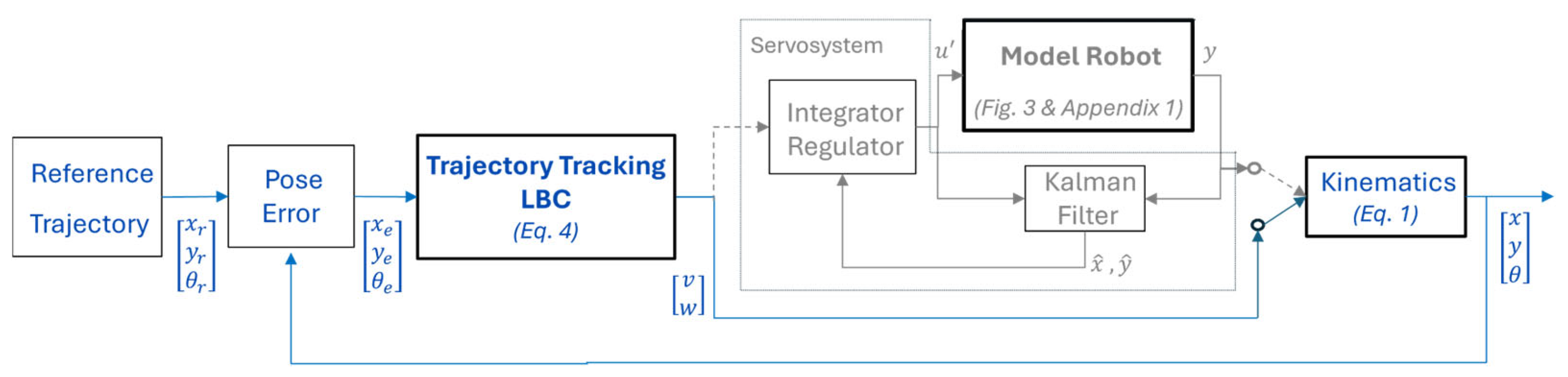
2.2.2. Nonlinear Trajectory Tracking: Lyapunov-Based Controller

For the nonlinear trajectory tracking, the strategy developed by Alcala et al. in the Elektra project [36] is applied for the control of an autonomous vehicle. The design process follows a structured sequence of steps, summarized as follows.
(a)
Consider the kinematics model of a unicycle mobile (Equation (1))
θ ˙ = w , x ˙ = v · c o s θ , y ˙ = v · s i n θ ,
being v the linear velocity, w the angular velocity, x ,   y   a n d   θ the robot pose in Cartesian space, and the upper dot means the time derivative.
(b)
Define the pose error e (Cartesian space): x e ,   ,   y e   a n d   θ e , respect to the desired values.
(c)
Obtain the time derivative of the pose error e ˙ .
(d)
Propose the Lyapunov Function V ( e ) , in this case:
V e =   1 2   x e 2 +   1 2   y e 2 +   1 2   θ e 2
(e)
Evaluate the time derivative of the Lyapunov Function V ˙ ( e ) , where the control vector ( v , w ) and the desired velocities ( v d   ,   w d ) according to the trajectory reference are involved,
V ˙ e = K 2 x e v d c o s θ e v + θ e w d w + K 2 y e v d s i n θ e
(f)
Propose a control law that guarantees stability of the control system, that means V ˙ ( e ) < 0 . In this case, the control law is:
v w = k 1   x e +   v d   c o s θ e w d +   k 2   v d   y e +   k 3   θ e  
being k 1 ,   ,   k 2   a n d   k 3 positive control gains.
(g)
Adjust the gains involved in the control law according to the desired trajectory tracking (see Appendix A.2).
At this stage of the design process, the dynamics related to the velocity servosystem (as described in [43]) is incorporated to validate the complete Simulink model, illustrated in Figure 5. The Kalman Filter provides the estimated state x ^ and the filtered output y ^ to close the servosystem loop. All the control gains involved in the global control solution depicted in Figure 5 are detailed in Appendix A.2.
Finally, following the same approach used for the implementation of DT, all control components shown in Figure 5—excluding the Robot Model—are deployed to the ECU-RBP using the Simulink Coder tool [36], allowing the acquisition of experimental results.

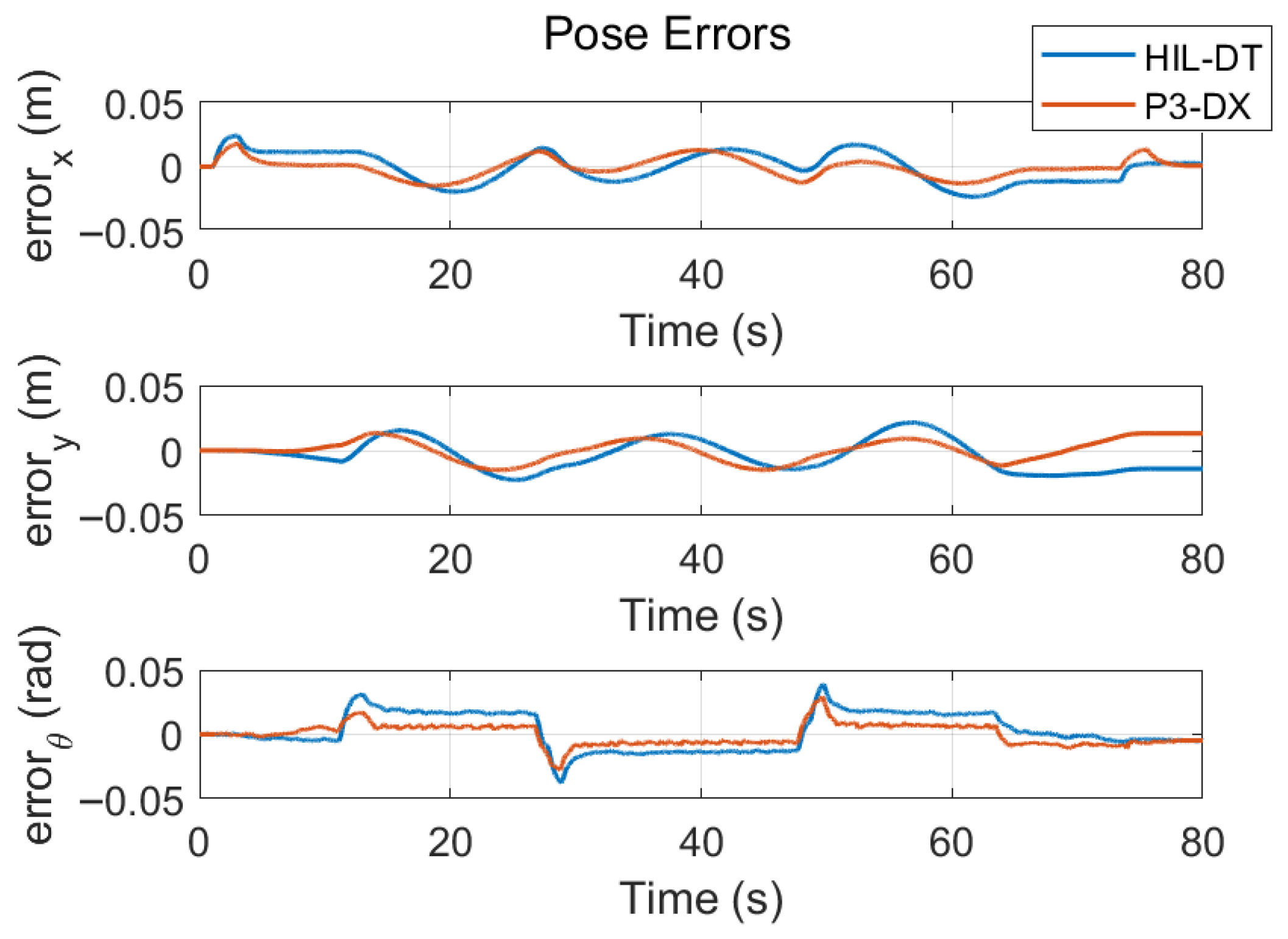
3. Experimental Results

In previous sections, the following aspects were presented: (a) theoretical ones supporting the algorithms running in the ECU-RBP and the DT-RBP, and (b) the hardware and software resources required to complete the test.
The P3-DX is a differential drive robot developed by MobileRobots Inc. It is made of an aluminium body (44 × 38 × 22 cm) with 16.5 cm diameter drive wheels. The two DC motors use 38.3:1 gear ratio and contain 500-tick encoders. The differential drive platform is non-holonomic and can rotate in place moving both wheels, or it can swing around a stationery wheel in a circle of 32 cm radius. A rear caster is included for balancing the robot. On flat floor, the P3-DX can move at speeds of 1.6 m/s. At slower speeds it can carry payloads up to 23 kg. In addition to motor encoders, the P3DX base includes eight ultrasonic transducer (range-finding sonar) sensors arranged to provide 180-degree forward coverage [41].
As a case study, the tracking of two different trajectories for the P3-DX is proposed.
The closed-loop solution comprising the ECU-RBP and the DT-RBP (i.e., virtual robot), is initially evaluated following the configuration shown in Figure 1 (right side). Subsequently, as indicated in Figure 1 (left side), the same electronic control unit (ECU-RBP) is applied to the physical robotic platform. In both configurations, the ECU-RBP and DT-RBP are connected to a host laptop, enabling testing and result evaluation through the Simulink graphical interface. Nevertheless, each RBP platform can execute its respective functions, control (ECU-RBP) and modeling (DT-RBP), independently in stand-alone mode. The experimental setup corresponding to this configuration is illustrated in Figure 6 and the real work scenario in the Engineering School at University of Alcala is shown in Figure 7.
In the first experiment, an eight-form trajectory reference is defined, starting from the coordinates (0, 0, 0) to the final target (0, 2, π). Figure 8a shows the results obtained from the DT (red line) and the robot (yellow line) with respect to the reference (blue line). Linear and angular velocities registered from the real (Robot) and virtual (DT) mobiles are depicted in Figure 8b. The highest difference is accumulated at the end of the trajectory.
To gain deeper insight into the advantages and limitations of the proposed experiment, the tracking errors shown in Figure 9 are analyzed. These include the position ( e x ,   e y ) and orientation ( e θ )   errors of the robot (red line) and the DT (blue line) along the trajectory. Compared to Figure 8, an increase in pose errors is observed during transitions in reference signals. However, the overall errors remain within acceptable margins, under 5 cm in X and Y, and under 0.05 rads in θ .
A longer trajectory, including a simulated disturbance at the plant input has also been tested. As shown in Figure 10, the trajectory starts at the door of the laboratory L03 (red dot) with a initial pose ( 0,0 , π / 2 ) and ends at the door of the OL5 (green dot) with a pose 3.80 , 6.80 , π / 2 , following the path represented in blue color. The measures of the corridor are also included.
The simulated disturbance, shown in Figure 11, is added to the angular velocity plant input to evaluate the behaviour of the control system.
Figure 12a shows the results obtained from the DT (red line) and the robot (yellow line) with respect to the reference (blue line), and Figure 12b presents the linear and angular velocities registered. The effects of the disturbance can be clearly observed from second 11 to 21, with changes in the output angular velocities and the trajectory followed, which are quickly corrected.
Finally, the tracking errors are also shown in Figure 13. As in the previous experiment, the values remain acceptable.

4. Discussion

The experimental results show the proposed low-cost HIL architecture effectively validating nonlinear control strategies for mobile robotics. It uses a Lyapunov-based Controller on an ECU-RBP integrated with a DT-RBP and the physical P3-DX robot via a wireless network. The control system consistently performs across DT and physical platforms, as evidenced in Figure 8a and Figure 12a. Both platforms accurately track the trajectories even with velocity disturbance. Velocity profiles in Figure 8b and Figure 12b confirm the DT’s dynamic behavior mirrors the physical robot, validating the DT model’s fidelity and the controller’s adaptability.
The implemented control architecture integrates both controller and plant (real and DT) through a wireless network, addressing not only theoretical challenges but also practical considerations that affect overall system performance. Firstly, although the plant model derived through a system identification process (as shown in Figure 3) includes inherent delays due to the wireless communication channel, these delays are not embedded in the DT-RBP model. This omission is intentional, as delays are already present in the current communication between the Electronic Control Unit (ECU-RBP) and the Robot-Based Platform (DT-RBP) and duplicating them would result in an unrealistic control response within the HIL context. Secondly, the wireless communication channel used during the experimental validation exhibited non-deterministic behavior. The observed variability in transmission delay led to fluctuations in the system response, highlighting the importance of accounting for such non-idealities when transitioning from simulation to physical implementation. Thirdly, minor adjustments of control gains were required for approaching control errors, from simulation to emulation with DT, and finally to implementation on the physical robot. As it is known, the behaviour of the process under control is slightly time variant due to changes in physical factors such as battery charge level, wheel pressure, or mechanical backlash, among others, as well as environmental conditions like floor surface and wireless signal quality. These practical aspects contribute to the slight discrepancies observed between the responses shown in Figure 8 and Figure 9. Despite these differences, the overall performance remains consistent and validates the proposed control strategy.

5. Conclusions

This study demonstrates the feasibility and effectiveness of using Hardware-in-the-Loop combined with DT (HIL-DT) to design and validate nonlinear control solutions for mobile robots with portable and low-cost hardware platforms. The proposed methodology shows that high-cost instrumentation is not required for developing and testing advanced control strategies. By leveraging widely available tools and open-source platforms, such as the Raspberry Pi (RBP) 4, both the controller and the process model (as a digital twin) can be deployed on the same embedded system.
The integration of Simulink support packages for RBP greatly simplifies the code generation process and enhances the portability of control solutions from simulation to embedded deployment. This feature enhances fast prototyping and reduces the complexity of the design workflow. The same electronic board allows the designer to implement the process model working as a virtual process. This way, the electronic resources are optimized and the methodology of design simplified. Once the global control solution is validated by simulation, an alternative to design onboard control and model code is to take advantage of the add-ons offered by some Computer-Aided Control System Design tools, that is the case of the support packages for RBP hardware available on Simulink. The use of a Lyapunov-based controller for nonlinear trajectory tracking was successfully implemented and tested on a P3-DX mobile robot. The control solution demonstrated robust performance despite system uncertainties and variable communication delays.
Overall, the presented case study validates the proposed methodology and highlights the potential of DT applications using RBP platforms in both academic and industrial contexts. Considering that the real process and the RBP-DT are nodes of the same wireless network, they could bidirectionally and periodically interchange data flow allowing the parameters self-adaptation of the Digital Twin model. This way a new research line is open for future work. Besides, scalability to multi-agent systems, real-time diagnostics, or adaptive control strategies based on DT may be explored as future research lines.

Author Contributions

Conceptualization, F.E.; methodology, C.L.-G.; formal analysis, F.E. and B.P.A.; experiment C.L.-G. and C.C.; writing; review, C.C. and B.P.A.; and supervision F.E. All authors have read and agreed to the published version of the manuscript.

Funding

This research was funded by the University of Alcala through the projects: Development of digital twin for test bench in control engineering formation (Ref UAH/EV-1545, UAH/EV1633) and Integration of Demand Response in Prosumer Energy Management (Ref PIUAH24/IA-020).

Data Availability Statement

The original contributions presented in this study are included in the article. Further inquiries can be directed to the corresponding author.

Conflicts of Interest

The authors declare no conflicts of interest.

Abbreviations

The following abbreviations are used in this manuscript:
DTDigital Twin
HILHardware-in-the-Loop
RBPRaspberry Pi
ECUElectronic Control Unit
LBC Lyapunov-based Controller
FPGAField Programmable Gate Array
DSPDigital Signal Processor
CPUCentral Process Unit
GPUGraphic Processing Unit
DCDirect Current motor
UDPUser Datagram Protocol

Appendix A

Appendix A.1. Identification Parameters

In Section 2.2.1 we focused on the interest of identifying the robot model from data registered from a real unit excited by velocity references running in the ECU-RBP, both wirelessly linked. The odometry of the robot allows the corresponding velocities according to the process dynamics. The values of the parameters appearing in Figure 3, related to the nonlinear and linear components of the P3-DX, are given Table A1.
Table A1. Parameters related to the identified model of the P3-DX.
ParameterValue
Ts25 ms
Delay q3 samples
Input vector size2
Output vector size2
State vector size8
Linear velocity saturation−0.7701 m/s, 0.7487 m/s
Angular velocity saturation−1.7700 rad/s, 1.7550 rad/s
Linear velocity dead-zone−0.0151 m/s, 0.0149 m/s
Angular velocity dead-zone−0.0300 rad/s, 0.0750 rad/s
α v 0.3984
α w 0.2287
β v 0.6014
β w 0.7706
K v −57 × 10−6
K w −36 × 10−6
Taking into account these parameters, the discrete-time linear model in the state space is represented by the following characteristic matrices:
A   =         β v α v 0 0 0 0 1 0 0           0 0           0 0 1 0 0 0 0 0 0 0 0 0 0 0 0 0 0 0 0 0 0     0           0     0           0 0 0 0 0     0           0     0           0 0 0 0 0 β w α w     0 0 0 0 1 0 0     0 0   0 0 1 0 0 ,   B   =   0 0 0 0 0 0 1 0 0 0 0 0 0 0 0 1 ,
C = 1 0 0 0 0 K w 0 0 0 K v 0 0 1 0 0 0 ,   D = 0 0 0 0

Appendix A.2. Control Gains of the Global Solution

In Section 2.2.2 we deal with the global control solution according to the scheme shown in Figure 5. The control gains obtained from the design process are included in Table A2.
Table A2. Control gains resulting from the global control design.
ParameterValue
Servo: Gain regulator Kr 0.75             0.31             0.34         0.14     0.43     0.09     0.07     0.09 0.25   0.09     0.08       0.12         2.98         0.65         0.64         0.44
Servo: Integral Gain Ki     0.29         0.12 0.10     0.76
LBC gainsK1 = 1.21, K2 = 1.30, K3 = 1.53

References

  1. Tumasov, A.V.; Vashurin, A.S.; Trusov, Y.; Evgeny, T. The Application of Hardware-in-the-Loop (HIL) Simulation for Evaluation of Active Safety of Vehicles Equipped with Electronic Stability Control Systems. Procedia Comput. Sci. 2019, 150, 309–315. [Google Scholar] [CrossRef]
  2. Lin, J.S.; Wang, Y.C.; Lin, C.L.; Ma, L.S. Adaptive Cruise Control System Combined with AIoT. In Proceedings of the International Conference on Consumer Electronics—Taiwan (ICCE-Taiwan), Taichung, Taiwan, 9–11 July 2024. [Google Scholar] [CrossRef]
  3. Suh, M.W.; Chung, J.H.; Seok, C.S.; Kim, Y.J. Hardware-in-the-loop simulation for ABS based on PC. Int. J. Veh. Des. 2004, 24, 157–170. [Google Scholar] [CrossRef]
  4. Temeltas, H.; Gokasan, M.; Bogosyan, S. Hardware in the Loop Robot Simulators for On-site and Remote Education in Robotics. Int. J. Eng. Educ. 2006, 22, 815–828. [Google Scholar]
  5. Grega, W. Hardware-in-the-loop simulation and its application in control education. In Proceedings of the FIE’99 Frontiers in Education. 29th Annual Frontiers in Education Conference. Designing the Future of Science and Engineering Education, San Juan, PR, USA, 10–13 November 1999; ISBN 0-7803-5643-8. [Google Scholar]
  6. Ahmed, A.H.; Alsharif, A.O.; Aburas, O.E. Low Cost Hardware-in-the-Loop Control Systems Using Microcontrollers. J. Alasmarya Univ. Basic Appl. Sci. 2021, 6, 587–606. [Google Scholar] [CrossRef]
  7. Zheng, J.L.; Zeng, Y.B.; Xu, H.; Liu, W.C.; Mou, D.; Zhao, Z.M. An Event-Based Synchronization Framework for Controller Hardware-in-the-loop Simulation of Electric Railway Power Electronics Systems. arXiv 2023, arXiv:2311.07036. [Google Scholar]
  8. Sanz, M.; Santamargarita, D.; Huerta, F.; Ochoa, D.; Lázaro, A.; Barrado, A. Reduced-Order Model of Power Converters to Optimize Power Hardware-In-the-Loop Technology in Dc-Distributed Systems. In Proceedings of the 2020 IEEE Applied Power Electronics Conference and Exposition (APEC), New Orleans, LA, USA, 15–19 March 2020. [Google Scholar] [CrossRef]
  9. Flack, C.; Ucer, E.; Smith, C.P.; Kisacikoglu, M. Controller Hardware-in-the-Loop Testing of Decentralized EV-Grid Integration. In Proceedings of the 2022 IEEE Power & Energy Society General Meeting (PESGM), Denver, CO, USA, 17–21 July 2022. [Google Scholar] [CrossRef]
  10. Wagg, D.; Worden, K.; Barthorpe, R.; Gardner, P. Digital Twins: State-of-The-Art Future Directions for Modelling and Simulation in Engineering Dynamics Applications. ASCE-ASME J. Risk Uncertain. Eng. Syst. Part B Mech. Eng. 2020, 6, 030901. [Google Scholar] [CrossRef]
  11. Segovia, M.; Garcia-Alfaro, J. Design, Modeling and Implementation of Digital Twins. Sensors 2022, 22, 5396. [Google Scholar] [CrossRef]
  12. Magalhães-Lima, L.G.; Soares-Ferreira, J.M.; Nascimento-Coelho, D.; Regis De Melo, R.; Souza Da Silva, W. Development and Validation of a Digital Twin for a 5-Revolute Joint Robotic Manipulator. In Proceedings of the 2025 Brazilian Conference on Robotics (CROS), Belo Horizonte, Brazil, 28–30 April 2025. [Google Scholar]
  13. Birk, W.; Hostettler, R.; Razi, M.; Atta, K.; Tammia, R. Automatic generation and updating of process industrial digital twins for estimation and control—A review. Front. Control. Eng. 2022, 3, 954858. [Google Scholar] [CrossRef]
  14. Jørgensen, B.N.; Howard, D.A. Digital Twins: Benefits, Applications and Development Process. In Proceedings of the EPIA Conference on Artificial Intelligence, Faial Island, Portugal, 5–8 September 2023. [Google Scholar] [CrossRef]
  15. Thelen, A.; Zhang, X.; Fink, O.; Lu, Y.; Ghosh, S.; Youn, B.D.; Todd, M.D.; Mahadevan, S.; Hu, C.; Hu, Z. A comprehensive review of digital twin—Part 1: Modeling and twinning enabling technologies. Struct. Multidiscip. Optim. 2022, 65, 354. [Google Scholar] [CrossRef]
  16. Thelen, A.; Zhang, X.; Fink, O.; Lu, Y.; Ghosh, S.; Youn, B.D.; Todd, M.D.; Mahadevan, S.; Hu, C.; Hu, Z. A comprehensive review of digital twin—Part 2: Roles of uncertainty quantification and optimization, a battery digital twin, and perspectives. Struct. Multidiscip. Optim. 2023, 66, 1. [Google Scholar] [CrossRef]
  17. Li, R.; Shang, X.; Wang, Y.; Liu, C.; Song, L.; Zhang, Y.; Gu, L.; Zhang, X. Research on Parameter Compensation Method and Control Strategy of Mobile Robot Dynamics Model Based on Digital Twin. Sensors 2024, 24, 8101. [Google Scholar] [CrossRef]
  18. Zhao, L.; Nie, Z.; Xia, Y.; Li, H. Virtual–Physical Tracking Control for a Car-Like Mobile Robot Based on Digital Twin Technology. IEEE Trans. Ind. Electron. 2024, 71, 16348–16356. [Google Scholar] [CrossRef]
  19. Stączek, P.; Pizoń, J.; Danilczuk, W.; Gola, A. A digital twin approach for the improvement of an autonomous mobile robots (AMR’s) operating environment—A case study. Sensors 2021, 21, 7830. [Google Scholar] [CrossRef]
  20. Wang, Y.; Zhao, X. A digital twin dynamic migration method for industrial mobile robots. Robot. Comput.-Integr. Manuf. 2025, 92, 102864. [Google Scholar] [CrossRef]
  21. Mihalic, F.; Truntic, M.; Hren, A. Hardware-in-the-Loop Simulations: A Historical Overview of Engineering Challenges. Electronics 2022, 11, 2462. [Google Scholar] [CrossRef]
  22. Arif, S.; Khan, A.; Rehman, S. A Lightweight Received Signal Strength Indicator Estimation Model for Low-Power Internet of Things Devices in Constrained Indoor Networks. Appl. Sci. 2025, 15, 3535. [Google Scholar] [CrossRef]
  23. Bruno, S.; Trifan, I.D.; Vita, L.; Loprencipe, G. Development of Low-Cost Monitoring and Assessment System for Cycle Paths Based on Raspberry Pi Technology. Infrastructures 2025, 10, 50. [Google Scholar] [CrossRef]
  24. Bueno, G.; Sanchez-Vargas, L.; Diaz-Maroto, A.; Ruiz-Santaquiteria, J.; Blanco, M.; Salido, J.; Cristobal, G. Real-Time Edge Computing vs. GPU-Accelerated Pipelines for Low-Cost Microscopy Applications. Electronics 2025, 14, 930. [Google Scholar] [CrossRef]
  25. Nichols, K.M.; Roembke, R.A.; Adamczyk, P.G. Real-Time Motor Control Using a Raspberry Pi, ROS, and CANopen over EtherCAT, with Application to a Semi-Active Prosthetic Ankle. Actuators 2025, 14, 84. [Google Scholar] [CrossRef]
  26. Alvarez-Oviedo, A.; Mamani-Villanueva, J.F.; Echaiz-Espinoza, G.A.; Mauricio-Villanueva, J.M.; Ortiz-Salazar, A.; Llanos-Villarreal, E.R. Design of a System for Driver Drowsiness Detection and Seat Belt Monitoring Using Raspberry Pi 4 and Arduino Nano. Designs 2025, 9, 11. [Google Scholar] [CrossRef]
  27. Dimitrov, K.; Chivarov, N.; Chivarov, S.; Paunova-Krasteva, T.; Filipov, E.; Daskalova, A. Concept of a Cyber–Physical System for Control of a Self-Cleaning Aquaponic Unit. AgriEngineering 2024, 6, 3843–3874. [Google Scholar] [CrossRef]
  28. Fazylova, A.; Tultayev, B.; Iliev, T.; Stoyanov, I.; Kabasheva, M.; Kosunalp, S. Experimental Study of an Industrial Data Transmission Network in the Automatic Control System of a Wind Turbine. Machines 2024, 12, 746. [Google Scholar] [CrossRef]
  29. Turlykozhayeva, D.; Temesheva, S.; Ussipov, N.; Bolysbay, A.; Akhmetali, A.; Akhtanov, S.; Tang, X. Experimental Performance Comparison of Proactive Routing Protocols in Wireless Mesh Network Using Raspberry Pi 4. Telecom 2024, 5, 1008–1020. [Google Scholar] [CrossRef]
  30. Drăgoi, M.V.; Nisipeanu, I.; Frimu, A.; Tălîngă, A.M.; Hadăr, A.; Dobrescu, T.G.; Suciu, C.P.; Manea, A.R. Real-Time Home Automation System Using BCI Technology. Biomimetics 2024, 9, 594. [Google Scholar] [CrossRef]
  31. Rsapberry Pi 4. Available online: https://www.raspberrypi.com/products/raspberry-pi-4-model-b/ (accessed on 20 March 2025).
  32. Walter, J.; Fakih, M.; Grüttner, K. Hardware-Based Real-Time Simulation on the Raspberry Pi. In Proceedings of the 2nd Workshop on High-Performance and Real-Time Embedded Systems (HiRES 2014), Vienna, Australia, 20–22 January 2014. [Google Scholar]
  33. Landolfi, E.; Salvi, A.; Troiano, A.; Natale, C. Hardware-in-the-loop validation of an adaptive model predictive control on a connected and automated vehicle. Int. J. Adapt. Control. Signal Process. 2023, 37, 1459–1491. [Google Scholar] [CrossRef]
  34. Amoozar, M.H.; Zhang, Y.M. Trajectory tracking of Wheeled Mobile Robots: A kinematical approach. In Proceedings of the 2012 IEEE/ASME 8th IEEE/ASME International Conference on Mechatronic and Embedded Systems and Applications, Suzhou, China, 8–10 July 2012. [Google Scholar] [CrossRef]
  35. Zambelli, M.; Karayiannidis, Y.; Dimarogonas, D.V. Posture regulation for unicycle-like robots with prescribed performance guarantees. IET Control. Theory Appl. 2015, 9, 192–202. [Google Scholar] [CrossRef]
  36. Alcala, E.; Puig, V.; Quevedo, J.; Escobet, T.; Comasolivas, R. Autonomous vehicle control using a kinematic Lyapunov-based technique with LQR-LMI tuning. Control. Eng. Pract. 2018, 73, 1–12. [Google Scholar] [CrossRef]
  37. Vazquez, M.; Ardito-Proulx, M.; Wadoo, S. Lyapunov Based Trajectory Tracking Dynamic Control for a QBOT-2. In Proceedings of the 2020 IEEE Integrated STEM Education Conference (ISEC), Princeton, NJ, USA, 1 August 2020. [Google Scholar] [CrossRef]
  38. Liu, M.; Fang, S.; Dong, H.; Xu, C. Review of digital twin about concepts, technologies, and industrial applications. J. Manuf. Syst. 2021, 58, 346–361. [Google Scholar] [CrossRef]
  39. Vered, Y.; Elliott, S.J. The use of digital twins to remotely update feedback controllers for the motion control of nonlinear dynamic systems. Mech. Syst. Signal Process. 2023, 185, 109770. [Google Scholar] [CrossRef]
  40. Saad, A.; Faddel, S.; Mohammed, O. IoT-based digital twin for energy cyber-physical systems: Design and implementation. Energies 2020, 13, 4762. [Google Scholar] [CrossRef]
  41. P3-DX Robot. Available online: https://www.generationrobots.com/media/Pioneer3DX-P3DX-RevA.pdf?srsltid=AfmBOopigKPz8ste_THqrR6Gy0mbhTVBrQ8hLlfLf8HZTO2f8OTK4PxR (accessed on 20 March 2025).
  42. Simulink Coder. Available online: https://ch.mathworks.com/products/simulink-coder.html (accessed on 20 March 2025).
  43. Cristina Losada-Gutiérrez, C.; Espinosa, F.; Santos-Pérez, C.; Marrón-Romera, M.; Rodriguez-Ascariz, J.M. Remote control of a robotic unit: A case study for control engineering formation. IEEE Trans. Educ. 2020, 63, 246–256. [Google Scholar] [CrossRef]
Figure 1. Key elements of the development environment used by authors for the nonlinear trajectory tracking of the P3-DX robot. The Electronic Control Unit (ECU-RBP) and the Robot Digital Twin (DT-RBP) are implemented in RBP 4 (model B).
Actuators 14 00376 g001
Figure 2. Development of methodology for DTs, from testing the real process to validate the virtual one.
Actuators 14 00376 g002
Figure 3. Linear and nonlinear components of the identified model of the P3-DX robot (a). Variable relationship and Simulink model (b).
Actuators 14 00376 g003
Figure 4. Simulink project to be downloaded on the DT-RBP working as a DT of the identified robotic unit.
Actuators 14 00376 g004
Figure 5. Block diagram to validate by simulation the global control solution for nonlinear trajectory tracking of the robotic unit.
Actuators 14 00376 g005
Figure 6. Set-up for obtaining experimental results working with the same electronic controller ECU-RBP applied to the virtual process (ECU-DT) or the real one (P3-DX robot).
Actuators 14 00376 g006
Figure 7. Real work scenario (laboratories corridor) for validating nonlinear trajectory tests with the P3-DX robotic platform remotely controlled by the ECU-RBP.
Actuators 14 00376 g007
Figure 8. (a). Comparison of reference and followed trajectories, by DT-RBP (red line) and P3-DX (yellow line) (b). Linear and angular velocities obtained from the real robot and its DT.
Actuators 14 00376 g008
Figure 9. Comparison of pose (position and orientation) errors once the control signals are applied from the ECU-RBP to the DT-RBP (blue line) and to the P3-DX (red line). Eight-form trajectory experiment.
Actuators 14 00376 g009
Figure 10. Layout of the laboratories corridor where the experiments are performed, including the robot’s reference path (blue line) and the start (red) and end (green) points of the path.
Actuators 14 00376 g010
Figure 11. Disturbance added to the angular velocity plant input.
Actuators 14 00376 g011
Figure 12. (a). Comparison of reference and followed trajectories, by DT-RBP (red line) and P3-DX (yellow line) (b). Output linear and angular velocities obtained from the real robot and its DT.
Actuators 14 00376 g012
Figure 13. Comparison of pose (position and orientation) errors once the control signals are applied from the ECU-RBP to the DT-RBP (blue line) and to the P3-DX (red line). S-form trajectory experiment.
Actuators 14 00376 g013
Table 1. Summary of the relevant literature.
Ref.Focus AreaResearch ObjectiveSorting
[1,2,3,29]AutomotiveHIL for ESC systemsNo
[4,5]EducationRobotic HILNo
[8,9]Power SystemsHIL DC and GridNo
[13,14,15]Control Modeling and OptimizationDT in controlNo
[30,31,32,33,34,35,36,37]RoboticsTrajectory TrackingNo
This researchElectronic Control HIL, DTYes
Disclaimer/Publisher’s Note: The statements, opinions and data contained in all publications are solely those of the individual author(s) and contributor(s) and not of MDPI and/or the editor(s). MDPI and/or the editor(s) disclaim responsibility for any injury to people or property resulting from any ideas, methods, instructions or products referred to in the content.

