Article

The Influence of Axial-Bearing Position of Active Magnetic Suspension Flywheel Energy Storage System on Vibration Characteristics of Flywheel Rotor

by
Lei Wang
,
Tielei Li
* and
Zhengyi Ren
College of Mechanical and Electrical Engineering, Harbin Engineering University, Harbin 150001, China
*
Author to whom correspondence should be addressed.
Actuators 2025, 14(6), 290; https://doi.org/10.3390/act14060290
Submission received: 19 April 2025 / Revised: 31 May 2025 / Accepted: 7 June 2025 / Published: 13 June 2025
(This article belongs to the Special Issue Actuators in Magnetic Levitation Technology and Vibration Control)

Abstract

This study introduces a flywheel rotor support structure for an active magnetic suspension flywheel energy storage system. In this structure, there is an axial offset between the axial-bearing position and the mass-center of the flywheel rotor, which affects the tilting rotation of the flywheel rotor and which causes the coupling between its tilting rotation and radial motion. Therefore, the influence of the bearing position on the vibration characteristics of the flywheel rotor is explored in this paper. The tilting rotation constraint of the flywheel rotor by axial active magnetic bearing (AAMB) is analyzed, and the radial active magnetic bearing (RAMB) is equivalently treated with dynamic stiffness and dynamic damping. Based on this, a dynamic model of the active magnetic suspension rigid flywheel rotor, considering the position parameter of the axial bearing, is established. To quantify the axial offset between the position of the AAMB and the mass-center of the flywheel rotor, the axial-bearing position offset ratio γ is defined. The variation trend of the vibration characteristics of flywheel rotor with γ is discussed, and its correctness is validated through experiments. It is indicated that, with the increase of γ, the second-order positive precession frequency of the flywheel rotor decreases obviously, and the influence of the gyroscope torque gradually weakens. Meanwhile, its second-order critical speed ω2c decreases significantly (when γ is 0.5, ω2c decreases by about 62%); ω2c corresponds to the inclined mode, revealing that the offset ratio γ has a prominent influence on the critical speed under this mode. In addition, as γ increases, the mass unbalance response amplitude of the flywheel rotor under the speed of ω2c decreases significantly. The reasonable design of the axial-bearing position parameter can effectively improve the operational stability of the active magnetic suspension flywheel energy storage system.

1. Introduction

The flywheel energy storage system, as a new type of energy-storage device, has broad application prospects in practical engineering fields, such as peak cutting and valley filling in electricity, uninterrupted power supply systems, and vehicle energy recovery, because of its advantages of high energy-storage density and energy-conversion efficiency, low environmental pollution, and long service life [1,2,3,4,5].
The flywheel energy storage system is a complex electromechanical system, and its development and design need to consider various performance requirements, such as operational stability, energy storage and release performance, and energy-loss characteristics [6]. As a supporting component of the flywheel rotor, the performance characteristics of bearings have a significant impact on the overall performance of the flywheel energy storage system. The bearing system used for supporting the flywheel rotor mainly includes the rolling bearing, fluid sliding bearing, permanent magnet bearing, active magnetic bearing (AMB), and high-temperature superconducting magnetic suspension bearing [7,8,9,10,11]. Among them, the magnetic levitation bearing owns the advantages of having no friction loss and a long service life; therefore, they are suitable as supporting components for the flywheel rotor. Permanent magnet bearings have the advantages of a simple structure, high reliability, and low cost, but they need to be mixed with other bearings and are commonly used as thrust bearings [12]. High-temperature superconducting magnetic bearings can achieve stable suspension of the rotor without the need for a controller, but a low-temperature environment needs to be created [13]. However, the active magnetic bearing (AMB) has the characteristics of adjustable stiffness and damping. When used AMB as the supporting component of the flywheel rotor, the active magnetic suspension flywheel energy-storage system can effectively control the critical speed of the flywheel rotor by adjusting the stiffness and damping of the AMB, keeping it away from the working speed and ensuring the operation stability of the flywheel rotor, as well as better adapting to various working environments.
The running stability of the active magnetic suspension flywheel energy storage system is closely related to the vibration characteristics of the flywheel rotor. However, the vibration characteristics of the flywheel rotor are directly related to the performance of the AMB and its supporting structure parameters. Although the structural forms of the AMB are diverse [14,15] and there are many control methods, such as PID control, self disturbance rejection control, and adaptive control [16,17,18,19], the electromagnetic force of the active magnetic bearing exhibits various nonlinear characteristics [20], and the flywheel rotor is an energy storage component with a large moment of inertia, high working speed, and obvious gyroscopic effect. This makes the design work of the AMB and the flywheel-rotor support structure face great challenges.
Therefore, it is crucial to clarify the relationship between the vibration characteristics of the flywheel rotor and the performance of the AMB and the support structure parameters of the flywheel rotor, which has been investigated by numerous researchers in recent years. Liu et al. [21] analyzed the influence of the control parameters and the position distribution of the radial magnetic bearing on the vortex frequency of the flywheel rotor in a 600 Wh active magnetic suspension system based on the simplified rotor dynamics model. Xiang et al. [22] analyzed the relationship among the vibration characteristics of the magnetic suspension rotor and the system parameters, as well as its tilt response under different disturbances utilizing theoretical modeling and experimental methods. It indicated that the support stiffness and damping of the magnetic suspension rotor could be changed by adjusting the proportional and derivative coefficients of the control system, making its natural frequency move away from the operating frequency to avoid resonance. Subsequently, they also conducted theoretical modeling and vibration analysis on the hybrid magnetic suspension flywheel, exploring its vibration phenomena and the corresponding vibration balancing method caused by the residual unbalanced mass of the flywheel rotor [23]. Ren et al. [24,25] established a three-dimensional finite element model of the active magnetic suspension flywheel rotor system using the FEA method, and obtained the modal shape and critical speed of the flywheel rotor; furthermore, based on the mass-center theorem, a dynamic model of this magnetic rigid flywheel rotor, considering the gyroscope effect and mass imbalance, was acquired. The radial displacement of the flywheel rotor and the variation law of the electromagnetic force of the radial electromagnetic bearing at various speeds were calculated and analyzed using the state variable method. Combining the permanent magnet thrust bearing with the radial active magnetic bearing can form a hybrid support system, and the permanent magnet bearing can supplement the active magnetic bearing by providing the bias magnetic flux and additional magnetic force, thus decreasing the energy consumption of the active magnetic bearing. Nikolaj et al. [26] investigated the application of permanent magnet thrust bearings in flywheel energy storage systems and proposed a fast and effective method for the determination on force, stiffness, and damping. Moreover, they also pointed out that the permanent magnet thrust bearing must have the lowest possible radial negative stiffness to decrease the workload of the radial active magnetic bearing. Tang et al. [27] established a model for calculating the stiffness of axial passive magnetic bearings (PMB), and in the case of considering the radial coupling of axial PMB, developed a calculation model of the stiffness and damping for electromagnetic bearings. The relationship between the modal frequency of the rotor in the magnetic control torque gyroscope and the stiffness and damping of the magnetic bearing was analyzed based on the finite element method. Ji et al. [28] derived an accurate expression for the nonlinear electromagnetic force of the active magnetic bearing and investigated the nonlinear response of a rotor supported by an eight-pole AMB system utilizing the multi-scale method. Furthermore, they explored the influences of the unbalanced eccentricity, as well as the ratio and the derivative gain of the controller on the nonlinear response of this system. Ali Kandil et al. [29]. studied the bifurcation behavior of the periodic motion in the 16-pole AMB rotor system under different control parameters. The research results indicate that under a constant stiffness coefficient, this system can exhibit one of three types of vibration motion (periodic, quasi-periodic, and chaotic motions), which mainly depends on the derivative gain coefficient. Li et al. [30] designed a 5-DOF AMB that can simultaneously provide radial, axial, and inclined suspension for a high-strength steel energy-storage flywheel without shaft and hub. Through theoretical and experimental analysis, it was concluded that this electromagnetic bearing could achieve stable suspension of the flywheel weighing 5510 kg with minimal current loss. Gao et al. [31] developed a magnetic-levitation flywheel battery structure and investigated the beat vibration phenomenon of the rotor when its rotation frequency was close to the natural frequency of the system by establishing the corresponding vibration model. The results suggested that decreasing the beat vibration could improve the rotation accuracy of the flywheel rotor and the control stability of the system, as well as reducing the low-frequency interference. Li et al. [32,33] designed and fabricated a 0.5 kW·h flywheel energy storage system, pointed out problems in the design, manufacturing, and testing of the rigid flywheel rotor, conducted overspeed tests on the designed flywheel rotor to verify its strength, and adopted a type of commercial AMB with decentralized control to support this rotor, achieving its stable operation at a maximum speed of 24,000 min−1.
However, the above investigation on the vibration characteristics of the flywheel rotor mainly concentrates in the structure and performance of the AMB, and there is relatively less research on the support structure of the flywheel rotor. The support structure of the flywheel rotor plays a critical role in its vibration characteristics. This study introduces a flywheel rotor support structure for an active magnetic suspension flywheel energy storage system, but in this structure, the relationship between the axial-bearing position parameters and the vibration characteristics of the flywheel rotor is still unclear. Consequently, this paper focuses on analyzing the influence of the axial bearing supporting position on the vibration characteristics of the flywheel rotor.
The outline of this article is organized as follows: Section 2 introduces a flywheel rotor support structure for the active magnetic suspension flywheel energy storage system, and analyzes the forces and motion constraints of the flywheel rotor in the structure; Section 3 derives the expressions of equivalent dynamic stiffness and dynamic damping of the RAMB, and establishes the dynamic mathematical model of the rigid flywheel rotor considering the influence of the AAMB position on the motion constraint of the flywheel rotor; Section 4 gives the solution for the characteristic frequency of the flywheel rotor and discusses its variation of the precession frequency and critical speed with the axial-bearing position; Section 5 explores the change rule of the mass unbalanced response of the flywheel rotor with the position of the axial magnetic bearing; Section 6 introduces the prototype of the active magnetic suspension flywheel energy storage system and the corresponding experimental testing process, and compares the measured and calculated results; and Section 7 gives the conclusion.

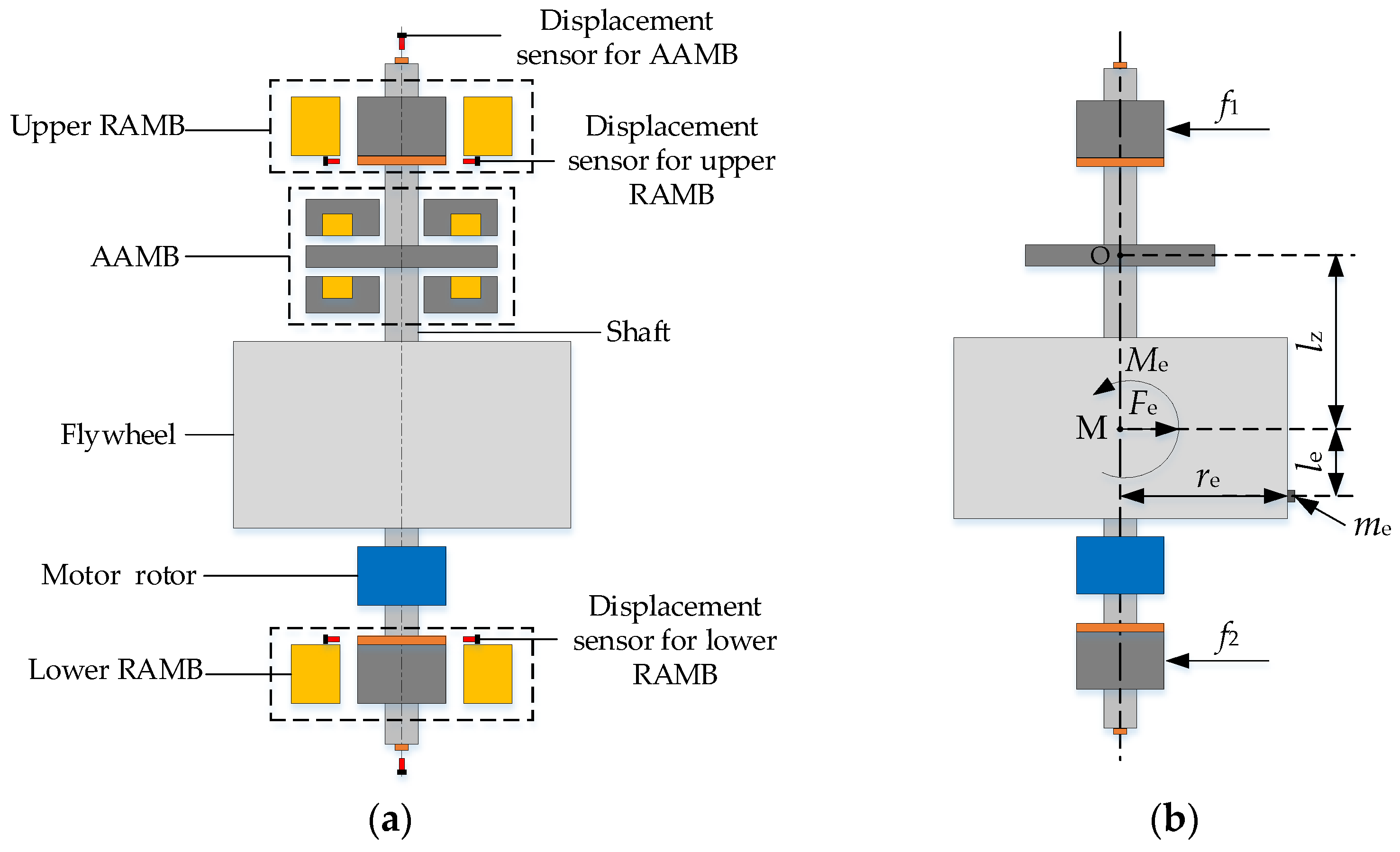
2. Description and Analysis of the Problem

The flywheel energy storage system is a kind of physical energy storage device that utilizes a high-speed rotating flywheel rotor for energy storage. In this study, the flywheel rotor support structure of the active magnetic suspension flywheel energy storage system is shown in Figure 1a. In this figure, the shaft, flywheel, motor rotor, and radial and axial active magnetic bearing rotors (RAMB rotor and AAMB rotor) are integrated together to form a flywheel rotor, which is a rotating energy-storage component. Due to the limitations of the flywheel rotor structure, there is a certain axial offset between the axial-bearing position and the mass-center of the flywheel rotor. Moreover, the displacement sensor in this figure is used to detect the position deviation information of the flywheel rotor and provide it to the control system of the active magnetic bearing (the control system of AMB), achieving suspension control of the flywheel rotor. Here, the PID controller is adopted, which has the advantages of a simple structure and strong reliability.
As shown in Figure 1a, this axial magnetic bearing mainly controls the axial motion of the flywheel rotor, but has no restriction on its radial movement. In addition, the tilting rotation of the flywheel rotor will rotate around the geometric center of this axial bearing. When the axial-bearing position coincides with the mass-center of the flywheel rotor, the tilting moment of inertia of the flywheel rotor is called its equatorial moment of inertia. When there is an axial displacement between the axial-bearing position and the mass-center of the flywheel rotor, the tilting moment of inertia of the flywheel rotor can be calculated using the parallel-axis theorem according to its equatorial moment of inertia and axial offset.
Figure 1b presents the force analysis diagram of the flywheel rotor. In the figure, point O represents the position of the axial bearing and point M represents the mass-center of the flywheel rotor. The distance lz between these two points is the axial offset between the axial-bearing position and the mass-center of the flywheel rotor. The relationship between the tilting moment of inertia Jdz of the flywheel rotor and the axial offset lz can be expressed as
J dz = J d + m l z 2
where Jd represents the equatorial moment of inertia of the flywheel rotor, and m represents the mass of the flywheel rotor.
Considering that the effect of mass imbalance has no impact on the critical speed discussed in this article, this paper mainly explores the influence rule of axial-bearing position on the mass imbalance response of the flywheel rotor. Therefore, in the process of dynamic modeling on the flywheel rotor, this paper adopts the unbalanced mass to describe the mass imbalance phenomenon of the flywheel rotor, as shown in Figure 1b. In this figure, f1 and f2 represent the electromagnetic forces of the upper and lower radial active magnetic bearings, which exert constraints on the radial motion of the flywheel rotor; me is the unbalanced mass. As the flywheel rotor rotates, the unbalanced force Fe and unbalanced moment Me generated by this unbalanced mass me will cause the vibration of the flywheel rotor. The calculation formulas for Fe and Me can be expressed as
F e = m e r e ω 2 = U e ω 2 ( t ) M e = m e r e l e ω 2 = U e l e ω 2 ( t )
where Ue = mere, re is the radius of the unbalanced mass; le is the distance from the unbalanced mass to the mass-center of the flywheel rotor; and ω(t) is the angular speed of the flywheel rotor, which is a function of time t. Here, the unbalanced force Fe and the unbalanced moment Me are variables that vary with a change of angular speed.
According to the above analysis, the existence of the axial offset lz between the axial-bearing position and the mass-center of the flywheel rotor will cause a change in the tilting moment of inertia of the flywheel rotor, thereby altering its natural vibration characteristics. The unbalanced mass on the flywheel rotor is a crucial factor causing the vibration of the flywheel rotor, and the mass imbalance response is an important parameter for its vibration analysis.
In addition, the coupling phenomenon between the tilting rotation and radial motion of the flywheel rotor caused by the axial offset lz will be stated during the model establishment. Considering that when the flywheel rotor tilts and rotates, the gravitational moment generated by its centroid is much smaller than the moment generated by the radial bearing, this gravitational moment was ignored in the model establishment.

3. Theoretical Modeling

This study first equivalently treats the electromagnetic force of RAMB, and then, based on the motion constraints of the axial magnetic bearing on the flywheel rotor, establishes the dynamic model of the active magnetic suspension rigid flywheel rotor considering the position of this axial bearing.

3.1. Equivalent Dynamic Stiffness and Damping of the Electromagnetic Force of Radial Active Magnetic Bearing

3.1.1. Linearization of the Electromagnetic Force of Radial Active Magnetic Bearing

For the octupole radial active magnetic bearing with differential control, the electromagnetic forces in the x and the y directions are independent of each other without considering the coupling of these two directions, and their calculation methods are the same. According to references [28,31], in the x direction, the calculation formula for the resultant force of the nonlinear electromagnetic force acting on the AMB rotor can be expressed as
F X = μ 0 N 2 S 4 ( I 0 i x ) 2 ( x 0 x ) 2 ( I 0 + i x ) 2 ( x 0 + x ) 2 cos α
where μ0 is the vacuum magnetic permeability (μ0 = 4π × 10−7); N is the number of coil turns in a pair of magnetic poles; S is the cross-sectional area of magnetic pole; α is half of the angle between the two magnetic poles (α = 22.5°); x0 is the standard air gap on one side of the AMB; x is the offset of the AMB rotor in the x direction; I0 is the bias current; and ix represents the control current.
Since the displacement x of the active magnetic bearing rotor is relatively small compared to the gap x0 between the rotor and stator, the linearization treatment on this non-linear electromagnetic force was conducted here [22]. Performing Taylor series expansion on Equation (3) and omitting its higher-order quantities above the second order, the expression for the linear electromagnetic force can be obtained:
F X = k x x + k i i x
where k x = μ 0 N 2 S I 0 2 x 0 3 cos α and k i = μ 0 N 2 S I 0 x 0 2 cos α are the stiffness coefficients of displacement and the current for the electromagnetic force.

3.1.2. Calculation of the Equivalent Dynamic Stiffness and Damping of Radial Active Magnetic Bearing

The control principle of the AMB using the PID controller is presented in Figure 2. In this figure, Gc(s) is the transfer function of the inexact differential PID controller, Ga(s) is the transfer function of the power amplifier, and Gs(s) is the displacement transfer function. The expression for these transfer functions can be stated as
G c ( s ) = K p + K i s + K d s 1 + T d s G a ( s ) = K a 1 + T a s G s ( s ) = K s 1 + T s s
where Ka and Ks are the coefficients of the power amplifier and displacement sensor; Ta, Ts and Td are the time constants of the power amplifier, displacement sensor, and differential element; Kp is the scale coefficient; Kd is the differential coefficient; and Ki is the integral coefficient.
When the input interference force q(t) acts on the RAMB rotor, it will cause the output of displacement x(t), and its transfer function is
X ( s ) Q ( s ) = ( m s 2 k x ) 1 1 G s ( s ) G c ( s ) G a ( s ) k i ( m s 2 k x ) 1 = 1 m s 2 k x G s ( s ) G c ( s ) G a ( s ) k i
Let s = j ω , and the frequency response equation can be obtained as
m ω 2 X ( j ω ) k x X ( j ω ) k i G s ( j ω ) G c ( j ω ) G a ( j ω ) X ( j ω ) = Q ( j ω )
The support characteristic of the RAMB is similar to that of the spring. The frequency response function of the mass-spring-damping system with a single degree of freedom can be expressed as
m ω 2 X ( j ω ) + k X ( j ω ) + j c ω X ( j ω ) = Q ( j ω )
where k and c are the stiffness and damping coefficients of the spring, respectively.
Comparing Equations (7) and (8), the stiffness coefficient ke and damping coefficient ce of the AMB can be obtained as follows:
k e = k i R e G s ( j ω ) G c ( j ω ) G a ( j ω ) k x c e = k i I m G s ( j ω ) G c ( j ω ) G a ( j ω ) / ω
where Re and Im represent the real and imaginary parts of Gs()Gc()Ga(), respectively; ω is the angular frequency of the flywheel rotor.
Substituting Equation (5) into Equation (9), the expressions for ke and ce can be derived as follows:
k e = A e ( 1 T s T a ω 2 ) ( K p + K d T d ω 2 1 + T d 2 ω 2 ) + ω ( T s + T a ) ( K i ω + K d ω 1 + T d 2 ω 2 ) k x c e = B e ( 1 T s T a ω 2 ) ( K i ω + K d ω 1 + T d 2 ω 2 ) ω ( T s + T a ) ( K p + K d T d ω 2 1 + T d 2 ω 2 )
where A e = k i K s K a ( 1 + T s 2 ω 2 ) ( 1 + T a 2 ω 2 ) ; B e = k i K s K a ω ( 1 + T s 2 ω 2 ) ( 1 + T a 2 ω 2 ) .
From Equation (10), it can be seen that the values of ke and ce change with the vibration angular frequency ω, so they are also called the equivalent dynamic stiffness and equivalent dynamic damping of the RAMB, respectively.

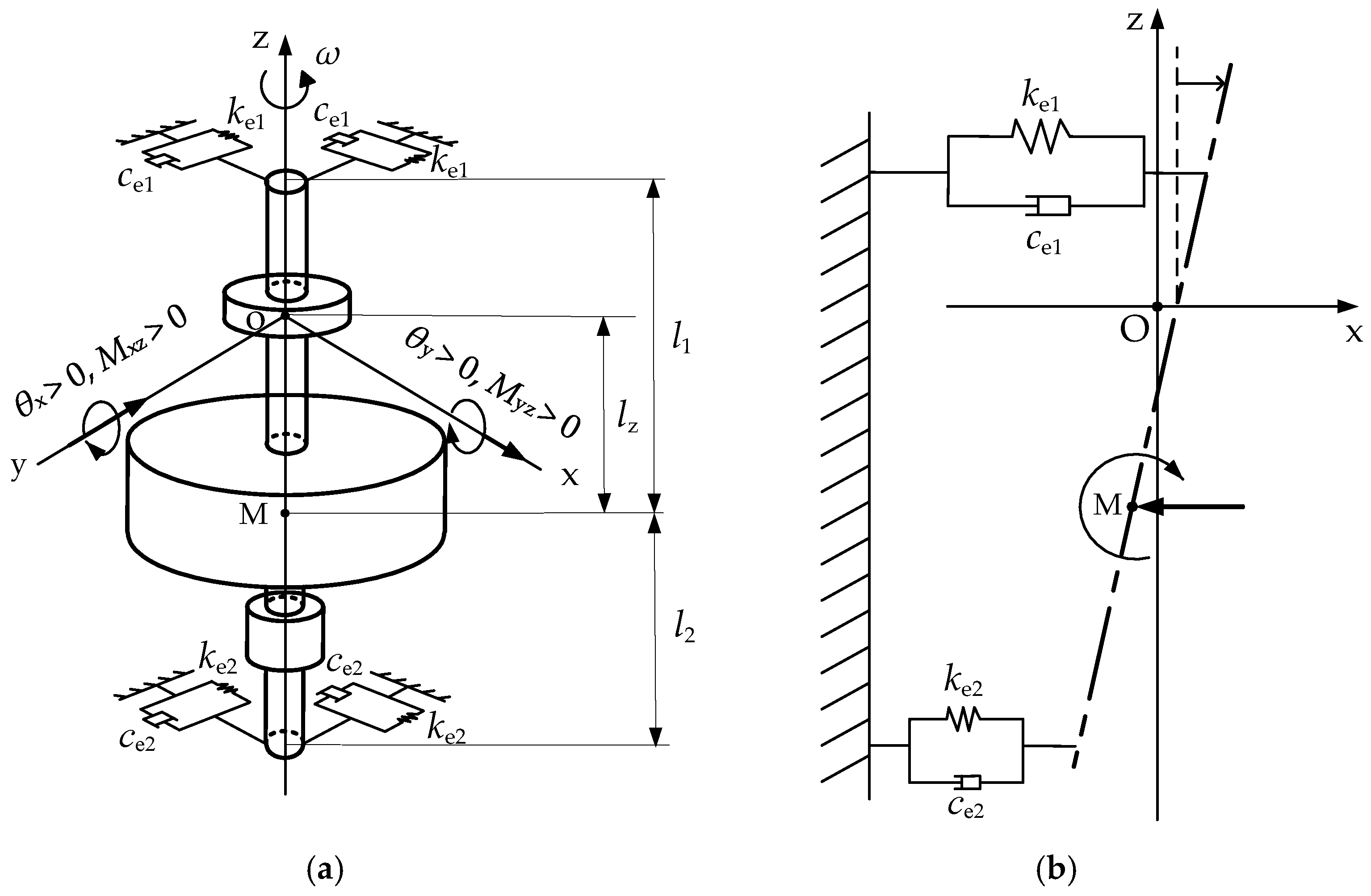
3.2. Dynamic Mathematical Model of Rigid Flywheel Rotor Considering the Position of Axial Active Magnetic Bearing

Assuming the flywheel rotor is a rigid rotor, the axial movement of the axial bearing rotor is not considered (that is, the axial motion of the flywheel rotor is completely restricted by the axial bearing). The mechanical relationship among the flywheel rotor and its supporting structure is described in Figure 3. In this figure, a fixed coordinate system o-xyz is established by taking the center O of the axial bearing rotor of the flywheel rotor in the static equilibrium state as the origin, using the equivalent dynamic stiffness (ke1, ke2) and dynamic damping (ce1, ce2) to represent the radial support force of the upper and lower radial active magnetic bearings acting on the flywheel rotor.
Furthermore, in Figure 3, M represents the mass-center of the flywheel rotor under ideal conditions (without considering unbalanced mass); l1 and l2 represent the distances from the upper and lower radial bearings to the mass-center of the flywheel rotor; lz is the distance between the axial bearing and the mass-center of the flywheel rotor; θx and θy are the inclination angles of the flywheel rotor around the x and y axes, and Mxz and Myz are the resultant moments of the radial bearing on the flywheel rotor around the y and x axes, respectively.
Due to the axial movement of the axial bearing rotor being constrained, the flywheel rotor will rotate around the center of this axial bearing rotor when it tilts. Considering that the inclination rotation angle θ of the flywheel rotor is small, sin θ ≈ θ and cos θ ≈ 1 can be given. Thus, the relationship between the positions (x1, y1), (x2, y2) of the upper and lower radial bearing rotors, the mass-center (xM, yM) of the flywheel rotor, and the position (x, y) of the axial bearing can be expressed as
x 1 = x + ( l 1 l z ) θ x x 2 = x ( l 2 + l z ) θ x y 1 = y + ( l 1 l z ) θ y y 2 = y ( l 2 + l z ) θ y x M = x l z θ x y M = y l z θ y
Analyzing Equation (11), it can be seen that if lz ≠ 0, then the values of (xM, yM) will be affected by (θx, θy), which indicates that when there exists an offset among the axial magnetic bearing and the mass-center of the flywheel rotor, and there will be a coupling effect between the radial motion of the flywheel rotor and its tilting rotation.
According to the principles of vector mechanics, angular momentum theorem, and gyroscopic moment theorem, combined with Equation (1), the differential equations of motion for the active magnetic suspension flywheel rotor can be expressed as
m x ¨ M ( t ) = F x + F ex m y ¨ M ( t ) = F y + F ey ( J d + m l z 2 ) θ ¨ x ( t ) = M xz J p ω θ ˙ y ( t ) + M ex ( J d + m l z 2 ) θ ¨ y ( t ) = M yz + J p ω θ ˙ x ( t ) + M ey
where Fx and Fy are the resultant forces of the upper and lower radial magnetic bearings on the flywheel rotor in the x and y directions; Fex, Fey and Mex, Mey are the unbalanced forces and moments generated by the unbalanced mass of the flywheel rotor in the x and y directions and around the y- and x-axes, respectively. Jd is the equatorial moment of inertia of the flywheel rotor; J p ω θ ˙ y ( t ) and J p ω θ ˙ x ( t ) are the gyroscopic moments produced by the flywheel rotor around the x- and y-axes, respectively.
According to the expression of equivalent stiffness and damping for the radial active magnetic bearing as well as Equation (11), parameters Fx and Fy in the equation system (12) can be expressed as
F x = k e 1 x 1 ( t ) c e 1 x ˙ 1 ( t ) k e 2 x 2 ( t ) c e 2 x ˙ 2 ( t ) F y = k e 1 y 1 ( t ) c e 1 y ˙ 1 ( t ) k e 2 y 2 ( t ) c e 2 y ˙ 2 ( t )
The axial active magnetic bearing constrains the axial motion of the flywheel rotor and its inclination rotation center, but it has no force constraint on its radial motion. The flywheel rotor rotates at an incline only when it is subjected to an unbalanced torque around its mass-center. Thus, for the moment generated by the supporting force of the upper and lower radial magnetic bearings, its force arms are l1 and l2, respectively (as presented in Figure 3a), and the parameters of Mxz and Myz in the Equation (12) can be expressed as
M xz = l 1 ( k e 1 x 1 ( t ) + c e 1 x ˙ 1 ( t ) ) + l 2 ( k e 2 x 2 ( t ) + c e 2 x ˙ 2 ( t ) ) M yz = l 1 ( k e 1 y 1 ( t ) + c e 1 y ˙ 1 ( t ) ) + l 2 ( k e 2 y 2 ( t ) + c e 2 y ˙ 2 ( t ) )
In addition, according to Equation (2), parameters Fex, Fey, Mex, and Mey in Equation (12) can be expressed as
F ex = U e ( a t + ω 0 ) 2 cos ( 0.5 a t 2 + ω 0 t + α 0 ) F ey = U e ( a t + ω 0 ) 2 sin ( 0.5 a t 2 + ω 0 t + α 0 ) M ex = U e l e ( a t + ω 0 ) 2 cos ( 0.5 a t 2 + ω 0 t + α 0 ) M ey = U e l e ( a t + ω 0 ) 2 sin ( 0.5 a t 2 + ω 0 t + α 0 )
where α0 is the initial angle; ω0 is the initial angular velocity; and a is the angular acceleration.
Combining Equation (11) with Equation (15), the dynamic mathematical model of the active magnetic suspension rigid flywheel rotor considering the position of the axial bearing can be obtained as follows:
m m l z m m l z J d + m l z 2 J d + m l z 2 x ¨ ( t ) y ¨ ( t ) θ ¨ x ( t ) θ ¨ y ( t ) + A C A C B D J p ( a t + ω 0 ) B J p ( a t + ω 0 ) D x ˙ ( t ) y ˙ ( t ) θ ˙ x ( t ) θ ˙ y ( t ) + E G E G F H F H x ( t ) y ( t ) θ x ( t ) θ y ( t ) = U e ( ( a t + ω 0 ) 2 cos ( 0.5 a t 2 + ω 0 t + α 0 ) ) U e ( ( a t + ω 0 ) 2 sin ( 0.5 a t 2 + ω 0 t + α 0 ) ) U e l e ( ( a t + ω 0 ) 2 cos ( 0.5 a t 2 + ω 0 t + α 0 ) ) U e l e ( ( a t + ω 0 ) 2 sin ( 0.5 a t 2 + ω 0 t + α 0 ) )
where A = c e 1 + c e 2 ; B = c e 1 l 1 c e 2 l 2 ; C = c e 1 ( l 1 l z ) c e 2 ( l 2 + l z ) ;
D = c e 1 l 1 ( l 1 l z ) + c e 2 l 2 ( l 2 + l z ) ; E = k e 1 + k e 2 ; F = k e 1 l 1 k e 2 l 2 ; and
G = k e 1 ( l 1 l z ) k e 2 ( l 2 + l z ) ; H = k e 1 l 1 ( l 1 l z ) + k e 2 l 2 ( l 2 + l z ) .

4. Influence of the Axial Active Magnetic Bearing Position on the Characteristic Frequency and Critical Speed of Flywheel Rotor

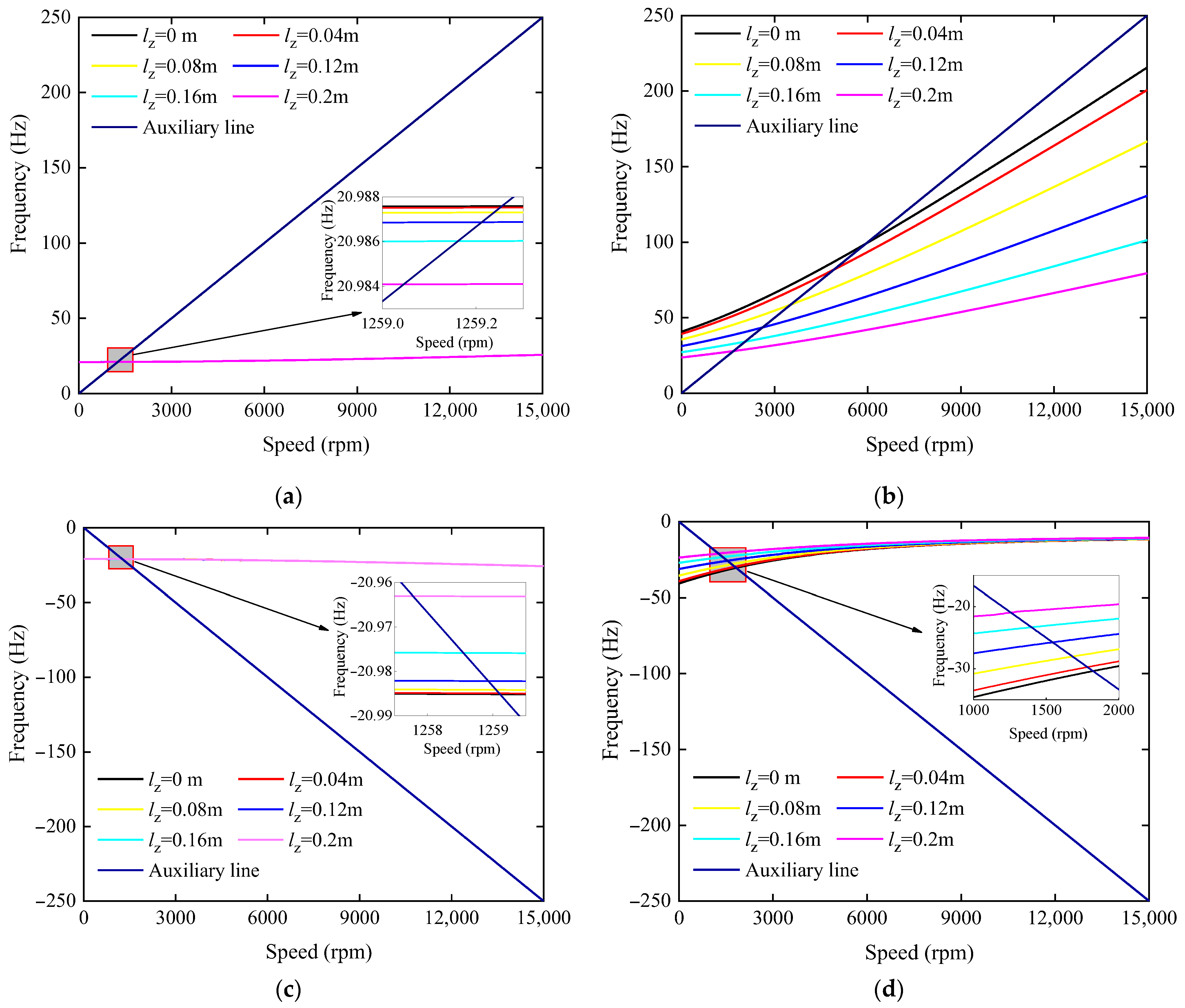
4.1. Solution and Analysis of the Characteristic Frequency of Flywheel Rotor

Since the unbalanced force does not affect the characteristic frequency (the inherent characteristic) of the flywheel rotor and the equivalent dynamic damping of the active magnetic bearing is small, Equation (16) is simplified by making Fex, Fey, Mex, Mey, ce1, ce2 equal to 0, and making a, α0 equal to 0, to solve and analyze the characteristic frequency of the flywheel rotor under undamped free vibration.
By simplifying Equation (16) as described above, the solution of this equation can be set as
x = A 1 cos ( p t + β ) , θ x = A 2 cos ( p t + β ) y = A 1 sin ( p t + β ) , θ y = A 2 sin ( p t + β )
By substituting Equation (17) into the simplified Equation (16) and organizing it, the following equation can be obtained:
( ( k e 1 + k e 2 ) m p 2 ) A 1 + ( m l z p 2 + ( k e 1 ( l 1 l z ) k e 2 ( l 2 + l z ) ) ) A 2 = 0 ( k e 1 l 1 k e 2 l 2 ) A 1 + ( J p p ω 0 ( J d + m l z 2 ) p 2 + k e 1 l 1 ( l 1 l z ) + k e 2 l 2 ( l 2 + l z ) ) ) A 2 = 0
By eliminating parameters A1 and A2 in Equation (18), the following characteristic equation can be obtained:
f p = ( ( k e 1 + k e 2 ) m p 2 ) ( J p p ω 0 ( J d + m l z 2 ) p 2 + ( k e 1 l 1 ( l 1 l z ) + k e 2 l 2 ( l 2 + l z ) ) ) ( m l z p 2 + ( k e 1 ( l 1 l z ) k e 2 ( l 2 + l z ) ) ) ( k e 1 l 1 k e 2 l 2 ) = 0
Solving the characteristic equation shown in Equation (19), the characteristic frequency of the flywheel rotor can be obtained. This is a fourth-order equation that can be solved to obtain the four characteristic frequencies of the flywheel rotor. If the characteristic frequency is a positive number, it represents the positive-precession frequency; if the characteristic frequency is a negative number, it demonstrates the anti-precession frequency, and its absolute value represents the magnitude of the anti-precession frequency.
Table 1 and Table 2 provide the relevant parameters of the flywheel rotor and the radial active magnetic bearing, respectively. By substituting these parameters into Equation (19), and setting different position offsets lz of the axial bearing and initial angular velocities ω0, the characteristic frequency variation curve of the flywheel rotor under different position offsets as speed can be obtained.
When the position offset lz of the axial active magnetic bearing is 0, 0.04, 0.08, 0.12, 0.16, and 0.2 m, respectively, the variation curves of the characteristic frequency (first- and second-order positive-precession frequencies; first- and second-order anti-precession frequencies) of the flywheel rotor with its rotation speed are as presented in Figure 4. In addition, the auxiliary line in this figure represents a line with the same value of characteristic frequency and rotation-speed frequency, used to determine the critical speed of the flywheel rotor; the rotation speed at the intersection of each auxiliary line and the precession frequency curve represents the critical speed of the flywheel rotor.
By analyzing Figure 4a,c, it can be seen that the change of the axial-bearing position has little effect on the first-order precession frequency of the flywheel rotor. As the axial-bearing position offset lz increases, the variation curve of the first-order positive precession frequency presents a slight downward trend overall, while its first-order anti-precession frequency curve slightly shifts upward overall. The intersection points between the auxiliary line and the first-order precession frequency curves in Figure 4a,c are close to each other, which means that the variation in the axial-bearing position has no clear influence on the first-order precession critical speed of the flywheel rotor.
Moreover, it can be seen from Figure 4b,d that the second-order precession frequency curve of the flywheel rotor changes obviously with the variation of the axial-bearing position offset lz. As lz increases, the second-order positive precession frequency curve of the flywheel rotor moves downward, that is, the second-order positive precession frequency of the flywheel rotor decreases with the increase of lz. Its second-order anti-precession frequency curve shows a significant change with the variation of lz in the lower speed range; as the ration speed increases, the second-order anti-precession frequency curves under different lz tend to approach each other. Among them, in the speed range of 0–5000 rpm, the second-order anti-precession frequency curve of the flywheel rotor moves upward with the increase of axial-bearing position offset lz, namely, its second-order anti-precession frequency decreases accordingly.
What is more, by observing Figure 4b,d, it can be seen that as the axial-bearing position offset lz increases, the variation range of the second-order precession frequency of the flywheel rotor with speed decreases. This indicates that the influence of gyro torque on the second-order precession frequency of the flywheel rotor gradually weakens with the increase of axial-bearing position offset lz. Correspondingly, as shown in Figure 4b,d, the rotation speed at the intersection point between the auxiliary line and the second-order precession frequency curve decreases with the increase of lz, which means that as the axial-bearing position offset lz increases, the second-order critical precession speed of the flywheel rotor decreases.

4.2. The Variation Rule of the Critical Speed of Flywheel Rotor with the Offset Ratio of Axial-Bearing Position

According to the variation curve of the characteristic frequency of the flywheel rotor with speed, the critical speeds of each order of the flywheel rotor can be obtained. From the characteristic frequency curves shown in Figure 4 in Section 4.1, four critical speeds can be acquired, which are the first- and second-order positive precession critical speeds and the first- and second-order anti-precession critical speeds. Among them, the first- and second-order positive precession critical speeds of the flywheel rotor are referred to as the first- and second-order critical speeds, which are also the actual critical speeds in practical engineering.
This section will explore the variation rule of the first-order critical speed ω1c and the second-order critical speed ω2c of the flywheel rotor with the position of the axial bearing. Here, the axial-bearing position offset ratio γ is utilized to characterize the relative position between the axial active magnetic bearing and the mass-center of the flywheel rotor. The definition of this position offset ratio γ is
γ = l z l 1
where lz represents the distance between the axial magnetic bearing and the mass-center of the flywheel rotor (namely, the position offset of the axial bearing); l1 represents the distance between the radial magnetic bearing on the side where the axial bearing is located and the mass-center of the flywheel rotor.
Figure 5 demonstrates the calculation results of the first-order critical speed ω1c and the second-order critical speed ω2c of the flywheel rotor under different axial-bearing position offset ratios γ.
By observing Figure 5, it can be seen that variation of the axial-bearing position offset ratio γ has no obvious effect on the first-order critical speed of the flywheel rotor, but has a significant impact on its second-order critical speed. As the axial-bearing position offset ratio γ increases, the first-order critical speed ω1c of the flywheel rotor changes slightly, while its second-order critical speed ω2c clearly decreases; when this offset ratio γ is 0.25 and 0.5, its second-order critical speed decreases by about 36% and 62%, respectively. With the increase of the offset ratio γ, the tilting moment of inertia of the flywheel rotor increases. And the increase of this moment of inertia reduces the critical speed of the flywheel rotor under the conical vibration mode. From the perspective that the second-order precession frequency of the flywheel rotor is affected by the gyroscopic torque, the second-order critical speed corresponds to the conical vibration shape. Therefore, as the offset ratio γ increases, the second-order critical speed of the flywheel rotor shows a prominent decreasing trend. Moreover, with the increase of the offset ratio γ, the increasing effect of gyroscopic torque on the second-order precession frequency of the flywheel rotor is weakened, which is also a factor causing the decrease of its second-order critical speed. It can be known from the above analysis that the second-order critical speed can be significantly reduced by increasing the distance between the axial-bearing position and the mass-center of the flywheel rotor. Therefore, through the rational design of the position of the axial active magnetic bearing, the second-order critical speed of the flywheel rotor can be controlled effectively, making it move away from the working speed range and improving the running stability of the active magnetic suspension flywheel energy storage system during the operation.

5. Influence of the Axial-Bearing Position on the Mass Unbalance Response of Flywheel Rotor

5.1. Solution and Analysis of the Mass Unbalance Response for Flywheel Rotor

The mass unbalance response is an important property for the flywheel rotor vibration. Therefore, this section mainly discusses the influence of the axial-bearing position on the mass unbalance response of the flywheel rotor. We set the unbalance Ue of the flywheel rotor as 8.9152 × 10⁻⁵ kg·m, the axial distance le from the unbalanced mass to the mass-center of the flywheel rotor as 0.08 m, the angular acceleration a as 3 rad/s2, and the maximum rotation speed of the flywheel rotor as 15,000 rpm. Using the fourth-order Runge–Kutta method to numerically solve Equation (16), the amplitude curves of the flywheel rotor at its upper and lower radial magnetic bearings could be obtained under different position offsets lz, and then the influence of the variation of axial-bearing position on the mass unbalance response of the flywheel rotor was analyzed.
When the position offset lz of the axial magnetic bearing, respectively, was 0, 0.04, 0.08, 0.12, 0.16, and 0.2 m, the variation curves of the vibration amplitude of the flywheel rotor at the position of its upper and lower radial magnetic bearings are as displayed in Figure 6 (The values of the curves in this figure are in the x direction, and the vibration amplitude of the flywheel rotor at the radial magnetic bearing is the same in both the x and y directions).
As can be seen from Figure 6a,b, within the speed range studied in this paper, the vibration amplitude curves under the different axial bearing offsets lz exhibit two peaks. The speeds corresponding to these peaks represent the first-order critical speed ω1c and the second-order critical speed ω2c of the flywheel rotor, respectively, and their values are consistent with the results obtained using the characteristic frequency curve in Section 4.2. In addition, analysis of Figure 6a,b shows that the vibration amplitude curve of the flywheel rotor at its upper and lower radial bearing positions has a similar variation law with the change of axial bearing offset lz. The change of this offset lz has no obvious effect on the first-order critical speed of the flywheel rotor and its vibration amplitude at this speed, while this has a significant effect on its second-order critical speed and vibration amplitude. As the axial-bearing position offset lz increases, the second-order critical speed ω2c of the flywheel rotor and its vibration amplitude at this speed exhibit a decreasing trend; meanwhile, in the higher speed range (6000–15,000 rpm), the vibration amplitude of the flywheel rotor decreases with the increase of lz.
Furthermore, according to the displacement parameters (x, y) and inclination parameters (θx, θy) of the flywheel rotor in the numerical solution of the mass unbalance response, the vibration shape of the flywheel rotor (namely, the trajectory of the flywheel rotor axis) under its first- and second-order critical speeds can be obtained, as presented in Figure 7.
It can be seen from Figure 7a,b that the flywheel rotor exhibits a translational vibration shape at its first-order critical speed, while it corresponds to a conical vibration mode at its second-order critical speed. The motion characteristics of the flywheel rotor under the translational vibration mode are mainly related to its mass m, supporting force Fx and Fy of the radial bearing as well as the unbalanced force Fe generated by the unbalanced mass of the flywheel rotor, while the motion characteristics of the flywheel rotor under the conical vibration mode are mostly affected by its tilting moment of inertia Jo, the supporting moments Mxz and Myz of the radial bearing, and the unbalance moment Me. The variation of the axial-bearing position mainly causes the significant changes in the tilting moment of inertia of the flywheel rotor and the supporting moment of the radial bearing; thus the change of the position of the axial active magnetic bearing has a prominent impact on the second-order critical speed of the flywheel rotor and its vibration amplitude at that speed.

5.2. The Variation Rule of the Mass Unbalance Response of Flywheel Rotor with the Position Offset Ratio of Axial Active Magnetic Bearing

This section further explores the variation rule of the mass unbalance response amplitude of the flywheel rotor with the position of the axial active magnetic bearing under different speeds. Here, the axial-bearing position offset ratio γ is utilized to characterize the relative position between the axial active magnetic bearing and the mass-center of the flywheel rotor. The definition of this offset ratio γ is presented in Equation (20).
Under the first-order critical speed ω1c and second-order critical speed ω2c, the variation curves of the mass unbalance response amplitude of the flywheel rotor at its upper and lower radial active magnetic bearing positions with the offset ratio γ are as demonstrated in Figure 8. In this paper, the vibration amplitude curves at the positions of the upper and lower radial bearings under the first-order critical speed ω1c are denoted as A u 1 c and A l 1 c ; correspondingly, the vibration amplitude curves under the second-order critical speed ω2c are denoted as A u 2 c and A l 2 c .
Analyzing Figure 8 shows that the variation of the axial-bearing position offset ratio γ has no clear influence on the vibration amplitude A u 1 c and A l 1 c , while it has a significant influence on A u 2 c and A l 2 c . As the position offset ratio γ increases, the vibration amplitude A u 2 c and A l 2 c of the flywheel rotor at its upper and lower radial bearing under the second-order critical speed decreases obviously. When the offset ratio γ is 0.25 and 0.5, the vibration amplitude decreases by about 40% and 65%, respectively. The flywheel rotor corresponds to a conical vibration mode under the second-order critical speed, where the vibration amplitude of the flywheel rotor at the upper and lower radial bearings is positively correlated with its inclination rotation angle. The tilting moment of inertia of the flywheel rotor increases with the increase of the position offset ratio γ of the axial bearing. The increase of this moment of inertia reduces the inclination rotation angle response of the flywheel rotor, thereby reducing the response amplitude of the flywheel rotor at its radial bearings. As this offset ratio γ increases, the second-order critical speed of the flywheel rotor decreases continuously, which results in the mass imbalance force at the second-order critical speed decreasing. This is also an important factor for the decrease in the unbalance response of the flywheel rotor under the second-order critical speed. Moreover, from the relative change trend between A u 2 c and A l 2 c shown in this figure, it can be seen that as the offset ratio γ increases, A l 2 c gradually approaches A u 2 c , and when γ is greater than about 0.6, A l 2 c is higher than A u 2 c . This indicates that the change of the axial-bearing position offset ratio γ not only affects the vibration amplitude of the flywheel rotor at its upper and lower radial bearings, but also affects the relative magnitude between them.
In addition, Figure 9 presents the variation curves of the vibration amplitude of the flywheel rotor at its upper and lower radial bearing positions with γ under the speeds of 6000 rpm, 9000 rpm, 12,000 rpm, and 15,000 rpm, which is denoted as A u 6000 and A l 6000 , A u 9000 and A l 9000 , A u 12000 and A l 12000 , and A u 15000 and A l 15000 , respectively.
By observing Figure 9a,b, it can be seen that when the rotation speed is 6000 rpm, 9000 rpm, 12,000 rpm, and 15,000 rpm, the variation of the axial-bearing position offset ratio γ has a prominent impact on the vibration amplitude of the flywheel rotor at its radial bearing positions. With the increase of the offset ratio γ, the vibration amplitudes A l 6000 , A l 9000 , A l 12000 , and A l 15000 of the flywheel rotor at its lower radial bearing position under different speeds all change gradually with a decreasing trend. This trend is more obvious when the offset ratio γ increases from 0 to 0.3, and gradually becomes stable when it is greater than 0.3. The vibration amplitudes A u 6000 , A u 9000 , A u 12000 , and A u 15000 of the flywheel rotor at its upper radial bearing decrease rapidly with the increase of the offset ratio γ, and then increase slightly. When γ is about 0.5, the vibration amplitude begins to increase slightly.
From the above analysis, it can be concluded that the variation of the axial active magnetic bearing position has no clear influence on the mass unbalance response amplitude of the flywheel rotor under its first-order critical speed, but its effect on that under the second-order critical speed, as well as at higher speed, is significant. Therefore, the appropriate position of the axial active magnetic bearing can effectively control the vibration amplitude of the flywheel rotor and can improve the operational stability of the active magnetic suspension flywheel energy storage system. Furthermore, as the position of the axial bearing varies, the relative magnitude between the vibration amplitude of the flywheel rotor at its upper and lower radial bearings also changes, that is, the appropriate position of the axial active magnetic bearing can also reduce the difference among the vibration amplitude of the flywheel rotor at its upper and lower radial active magnetic bearings, ensuring the force balance of the upper and lower radial active magnetic bearings.

6. Experiment

6.1. The Process of Experiment

The prototype platform of the vertical magnetic suspension flywheel energy storage system is as demonstrated in Figure 10a. Therein, the structure of the flywheel rotor is shown in Figure 10b. In this prototype, the distance between the axial active magnetic bearing and the mass-center of flywheel rotor is 0.145 m, and its other structural and control parameters are as listed in Table 1 and Table 2. In addition, the detection of the rotor displacement parameters of the radial and axial active magnetic bearings was conducted using eddy current displacement sensors (with a linear range of 2 mm and a resolution of 0.1 μm), and the relative position of this sensor is as shown in Figure 1a.
In Figure 10, the abbreviation AMB represents the active magnetic bearing, AAMB represents the axial active magnetic bearing, and RAMB represents the radial active magnetic bearing. As shown in this figure, during the experimental testing process, first the active magnetic bearing control system and power supply were turned on to make the flywheel rotor stably suspended. Then, the motor was turned on to accelerate the flywheel rotor. In LabView, NI-DAQmax was adopted to control the data acquisition card (NI-PXI6259), and the sampling frequency was set to 3000 Hz to detect the voltage signal of the eddy current displacement sensor in the radial active magnetic bearing. Finally, by transforming the collected signal through the conversion relationship between voltage and displacement in this displacement sensor, the vibration amplitude of the flywheel rotor at the positions of the upper and lower radial active magnetic bearings was obtained.

6.2. Analysis of Experimental Results

During the speed increase from 0 to 7800 rpm, the measured vibration amplitude A u e and A l e for the flywheel rotor at its upper and lower radial active magnetic bearings, and the calculated results A u t and A l t were as shown in Figure 11a,b. Here, the distance from the axial active magnetic bearing to the mass-center of flywheel rotor is 0.145 m.
By analyzing the data curves in Figure 11, it can be seen that the measured and calculated amplitude curves of the flywheel rotor at the upper and lower radial active magnetic bearings presents good consistency in terms of the overall variation trend, but there is a certain deviation in the numerical values. Among them, the experimental results of the first- and second-order critical speed of the flywheel rotor are about 1165 rpm and 2155 rpm, respectively, and their theoretical values are 1278 rpm and 2238 rpm. The relative errors between the experimental and theoretical values are 9.7% and 3.8%, respectively. In addition, by analyzing Figure 11a,b, it can be seen that the relative error between the measured and calculated results of the vibration amplitude is relatively clear. This is mainly due to the existence of some deviations between the experimental testing system and the ideal system, which will lead to some errors among the measured and calculated amplitude curves. In addition, the presence of interference signals in the eddy current displacement sensor can also cause some deviations in the vibration amplitude. According to the above analysis between the experimental and theoretical results, although there are some deviations in numerical value among them, their overall variation trend has good agreement, proving the validity of the results calculated from the mathematical model established in this work, and thus demonstrating the correctness of the conclusions drawn in this paper.

7. Conclusions

This study introduced an active magnetic suspension flywheel rotor support structure suitable for the flywheel energy storage system. In this paper, a dynamic mathematical model of the magnetic suspension rigid flywheel rotor, considering the position parameter of the axial bearing, was established, and the influence of the position parameter of the axial active magnetic bearing on the vibration characteristics of the flywheel rotor in this structure was analyzed. Finally, the correctness of the results obtained from the mathematical model established in this paper was validated through experiments. The concluded results were as follows:
The variation of the position parameter of the axial active magnetic bearing had no obvious effect on the first-order precession frequency of the flywheel rotor, but this had a prominent impact on its second-order precession frequency. As the position offset of this axial bearing increased, the second-order precession frequency of the flywheel rotor decreased significantly, and the influence of the gyroscope torque gradually weakened;
With the increase of the position offset ratio γ of axial bearing, the first-order critical speed of the flywheel rotor changed slightly, while its second-order critical speed decreased obviously. When this offset ratio γ was 0.25 and 0.5, its second-order critical speed was reduced by about 36% and 62%, respectively. Through the rational design of the axial-bearing position, the second-order critical speed of the flywheel rotor could be effectively reduced, making it move away from the working speed range and improving the operational stability of the active magnetic suspension flywheel energy storage system during the working process;
The change in the axial active magnetic bearing position had no clear influence on the mass unbalance response amplitude of the flywheel rotor under its first-order critical speed, but its effect on this under the higher speed was notable. As the position offset ratio γ of this axial bearing increased, the mass unbalance response amplitude of flywheel rotor under the second-order critical speed clearly decreased. At the higher speeds, the mass unbalance response amplitude decreased significantly at first and then became stable. By designing the position of the axial active magnetic bearing reasonably, the mass unbalance response amplitude of the flywheel rotor could be reduced effectively and the operational stability of the active magnetic suspension flywheel energy storage system could be improved.

Author Contributions

Conceptualization, L.W.; methodology, L.W.; software, L.W.; validation, L.W., T.L. and Z.R.; investigation, L.W.; resources, T.L. and Z.R.; data curation, L.W.; writing—original draft preparation, L.W.; writing—review and editing, L.W.; visualization, L.W.; supervision, T.L. and Z.R. All authors have read and agreed to the published version of the manuscript.

Funding

This work is supported by the National High-tech Research and Development Program of China (Grant No. 2013AA050802) and the Fundamental Research Special Funds for the Central Universities of Harbin Engineering University (Grant No. HEUCFZ1024).

Data Availability Statement

The data presented in this study are available on request from the corresponding author.

Conflicts of Interest

The authors declare no conflicts of interest.

References

  1. Koohi-Fayegh, S.; Rosen, M.A. A review of energy storage types, applications and recent developments. J. Energy Storage 2020, 27, 101047. [Google Scholar] [CrossRef]
  2. Qi, X.; Zhang, K.; Wang, G.; Fu, Z.; Dong, Y. Technology of Magnetic Flywheel Energy Storage. In Proceedings of the International Conference on Manufacturing Science and Materials Engineering (ICMSEM 2011), Shanghai, China, 14–15 October 2011. [Google Scholar]
  3. Tziovani, L.; Hadjidemetriou, L.; Charalampous, C.; Tziakouri, M.; Timotheou, S. Energy Management and Control of a Flywheel Storage System for Peak Shaving Applications. IEEE Trans. Smart Grid 2021, 12, 4195–4207. [Google Scholar] [CrossRef]
  4. Hopf, T.; Richter, M.; Schüßler, B.; Rinderknecht, S. Control Strategies for Highly Gyroscopic Outer Rotors with Diametral Enlargement in Active Magnetic Bearings. Actuators 2022, 11, 91. [Google Scholar] [CrossRef]
  5. Rupp, A.; Baier, H.; Mertiny, P.; Secanell, M. Analysis of a flywheel energy storage system for light rail transit. Energy 2016, 107, 625–638. [Google Scholar] [CrossRef]
  6. Venturini, S.; Cavallaro, S.P.; Vigliani, A. Windage loss characterisation for flywheel energy storage system: Model and experimental validation. Energy 2024, 307, 132641. [Google Scholar] [CrossRef]
  7. Wang, H.C.; Du, Z.M. Dynamic analysis for the energy storage flywheel system. J. Mech. Sci. Technol. 2016, 30, 4825–4831. [Google Scholar] [CrossRef]
  8. Liu, S.G.; Jiang, J. Technical Evolution of Advanced Flywheel Energy Storage System. In Proceedings of the 38th Chinese Control Conference, Guangzhou, China, 27–30 July 2019. [Google Scholar]
  9. Yuan, Y.; Sun, Y.; Xiang, Q. Design and Analysis of a Magnetic Bearings with Three Degrees of Freedom. Chin. J. Mech. Eng. 2019, 32, 3. [Google Scholar] [CrossRef]
  10. Amiryar, M.E.; Pullen, K.R. A Review of Flywheel Energy Storage System Technologies and Their Applications. Appl. Sci. 2017, 7, 286. [Google Scholar] [CrossRef]
  11. Yu, Z.; Zhang, G.; Qiu, Q.; Zhang, D.; Sun, X.; Wang, Y.; Liu, Y.; Feng, W.; Li, W.; Ai, L. Electromagnetic and Rotational Characteristics of a Superconducting Flywheel Energy Storage System Utilizing a Radial-Type High-Temperature Superconducting Bearing. J. Supercond. Nov. Magn. 2019, 32, 1605–1616. [Google Scholar] [CrossRef]
  12. Bonisoli, E.; Venturini, S.; Cavallaro, S.P. Nonlinear characterisation of a rotor on passive magnetic supports. Int. J. Mech. Control 2022, 23, 121–128. [Google Scholar]
  13. Tang, W.B.; Xiao, L.Y.; Ai, L.W.; Miao, S.; Wang, D.Y.; Han, R.L.; Fan, Z.M. A Novel Axial High-Temperature Superconducting Magnetic Bearing With Simple Structure and Large Suspension Force. IEEE Trans. Appl. Supercond. 2023, 33, 4601811. [Google Scholar] [CrossRef]
  14. Matsuda, K.; Kanemitsu, Y.; Kijimoto, S. Optimal number of stator poles for compact active radial magnetic bearings. IEEE Trans. Magn. 2023, 43, 3420–3427. [Google Scholar] [CrossRef]
  15. Li, Q.; Hu, Y.; Wu, H. Structure Design and Optimization of the Radial Magnetic Bearing. Actuators 2023, 12, 27. [Google Scholar] [CrossRef]
  16. Anantachaisilp, P.; Lin, Z. Fractional Order PID Control of Rotor Suspension by Active Magnetic Bearings. Actuators 2017, 6, 4. [Google Scholar] [CrossRef]
  17. Jeon, H.W.; Lee, C.W. Proportional-integral-derivative control of rigid rotor-active magnetic bearing system via eigenvalue assignment for decoupled translational and conical modes. J. Vib. Control 2015, 21, 2372–2393. [Google Scholar] [CrossRef]
  18. Li, B.L.; Li, Z.; Zhang, P.M.; Zhu, Z.D. Sliding mode active disturbance rejection decoupling control for active magnetic bearings. Electr. Mach. Control 2021, 25, 129–138. [Google Scholar]
  19. Khayyam, U.; He, B.X.; Hassan, S.U. Active Magnetic Bearing Design and Backstepping-Adaptive Control for High-Speed Rotors. In Proceedings of the 6th International Conference on Electrical Engineering, Control and Robotics (EECR)/3rd International Conference on Intelligent Control and Computing (ICICC), Xiamen, China, 10–12 January 2020. [Google Scholar]
  20. Ji, J.C.; Hansen, C.H.; Zander, A.C. Nonlinear dynamics of magnetic bearing systems. J. Intell. Mater. Syst. Struct. 2008, 19, 1471–1491. [Google Scholar] [CrossRef]
  21. Liu, J.N.; Ren, Z.Y.; Wu, S.W.; Tang, Y.L. Theoretical Vibration Analysis on 600 Wh Energy Storage Flywheel Rotor—Active Magnetic Bearing System. Int. J. Rotating Mach. 2013, 2013, 512674. [Google Scholar] [CrossRef]
  22. Xiang, B.; Wong, W.O. Vibration characteristics analysis of magnetically suspended rotor in flywheel energy storage system. J. Sound Vib. 2019, 444, 235–247. [Google Scholar] [CrossRef]
  23. Xiang, B.; Wen, T.; Liu, Z. Vibration analysis, measurement and balancing of flywheel rotor suspended by active magnetic bearing. Measurement 2022, 197, 111305. [Google Scholar] [CrossRef]
  24. Ren, Z.Y.; Liu, J.N.; Han, Y.J.; Teng, W.Q. Modal Analysis on 600 Wh Energy Storage Flywheel Rotor System. Key Eng. Mater. 2014, 572, 521–524. [Google Scholar] [CrossRef]
  25. Ren, Z.Y.; Huang, T.; Feng, J.J.; Zhou, Y.W. Kinematics analysis of vertical magnetic suspension energy storage flywheel rotor under transient rotational speed. In Proceedings of the 6th International Conference on Computer-Aided Design, Manufacturing, Modeling and Simulation (CDMMS), Busan, Republic of Korea, 14–15 April 2018. [Google Scholar]
  26. Dagnaes-Hansen, N.A.; Santos, I.F. Permanent magnet thrust bearings for flywheel energy storage system: Analytical, numerical, and experimental comparisons. Proc. IMechE Part C J. Mech. Eng. Sci. 2019, 233, 095440621984395. [Google Scholar] [CrossRef]
  27. Tang, J.Q.; Xiang, B.A.; Zhang, Y.B. Dynamic characteristics of the rotor in a magnetically suspended control moment gyroscope with active magnetic bearing and passive magnetic bearing. ISA Trans. 2014, 53, 1357–1365. [Google Scholar] [CrossRef]
  28. Ji, J.C.; Hansen, C.H. Non-linear oscillations of a rotor in active magnetic bearings. J. Sound Vib. 2011, 240, 599–612. [Google Scholar] [CrossRef]
  29. Kandil, A.; Sayed, M.; Saeed, N.A. On the nonlinear dynamics of constant stiffness coefficiennts 16-pole rotor active magnetic bearings system. Eur. J. Mech. A-Solids 2020, 84, 104051. [Google Scholar] [CrossRef]
  30. Li, X.J.; Palazzolo, A.; Wang, Z.Y. A Combination 5-DOF Active Magnetic Bearing For Energy Storage Flywheel. IEEE Trans. Transp. Electr. 2021, 7, 2344–2355. [Google Scholar] [CrossRef]
  31. Gao, H.; Yu, X.H.; Cao, J.N. Linear electromagnetic force and beat phenomenon for maglev flywheel battery. Int. J. Appl. Electromagn. Mech. 2019, 60, 409–421. [Google Scholar] [CrossRef]
  32. Li, X.; An, J.; Erd, N.; Dietz, D.; Gemeinder, Y.; Binder, A. Design and Manufacture of a High-speed Rotor in a Flywheel Demonstrator. In Proceedings of the 23rd International Conference on Electrical Machines and Systems (ICEMS), Hamamatsu, Japan, 24–27 November 2020. [Google Scholar]
  33. Li, X.; Dietz, D.; An, J.; Erd, N.; Gemeinder, Y.; Binder, A. Manufacture and Testing of a Magnetically Suspended 0.5-kWh Flywheel Energy Storage System. IEEE Trans. Ind. Appl. 2022, 58, 6152–6162. [Google Scholar] [CrossRef]
Figure 1. Support structure of the flywheel rotor and its force analysis diagram: (a) support structure of the flywheel rotor; (b) the diagram of the force analysis for flywheel rotor.
Actuators 14 00290 g001
Figure 2. Control principle of PID for AMB.
Actuators 14 00290 g002
Figure 3. The mechanical relationship between the flywheel rotor and its supporting structure: (a) the diagram of its overall force analysis; (b) the diagram of its force analysis in x-direction.
Actuators 14 00290 g003
Figure 4. The variation curve of the characteristic frequency of flywheel rotor with its rotation speed under different offsets lz: (a) first-order positive-precession frequency; (b) second-order positive-precession frequency; (c) first-order anti-precession frequency; (d) second-order anti-precession frequency.
Actuators 14 00290 g004
Figure 5. The variation curves of the first- and second-order critical speeds of the flywheel rotor with the offset ratio γ.
Actuators 14 00290 g005
Figure 6. Amplitude curve of the flywheel rotor at the radial magnetic bearing under different position offsets lz: (a) the amplitude curve of flywheel rotor at the upper radial magnetic bearing; (b) the amplitude curve of flywheel rotor at the lower radial magnetic bearing.
Actuators 14 00290 g006
Figure 7. The vibration shape of flywheel rotor under its first- and second-order critical speeds: (a) first-order vibration shape; (b) second-order vibration shape.
Actuators 14 00290 g007
Figure 8. The variation curve of the vibration amplitude of the flywheel rotor at its radial bearing with the offset ratio γ under the first- and second-order critical speeds.
Actuators 14 00290 g008
Figure 9. Under different speeds, the variation curves of the vibration amplitude of flywheel rotor at its radial bearing with the offset ratio γ: (a) vibration amplitude curves under the speeds of 6000 rpm and 9000 rpm; (b) vibration amplitude curves under the speeds of 12,000 rpm and 15,000 rpm.
Actuators 14 00290 g009
Figure 10. The experimental testing platform: (a) prototype of the vertical magnetic suspension flywheel energy storage system; (b) the structure of the flywheel rotor.
Actuators 14 00290 g010
Figure 11. The measured and calculated vibration amplitude curves of flywheel rotor at its upper and lower radial active magnetic bearings: (a) the upper radial active magnetic bearing; (b) the lower radial active magnetic bearing.
Actuators 14 00290 g011
Table 1. Structural and physical parameters of the flywheel rotor.
ParameterValue
Mass (m)56 kg
Moment of inertia (Jp)0.93 kg·m2
Equatorial moment of inertia (Jd)1.14 kg·m2
Distance from the upper radial magnetic bearing to the mass-center of the flywheel rotor (l1)0.282 m
Distance from the lower radial magnetic bearing to the mass-center of the flywheel rotor (l2)0.273 m
Table 2. Parameters of the radial active magnetic bearing.
TypeParameterValue
Structure and physical parametersCross-sectional area of magnetic pole (S)784 mm2
The turns for a pair of magnetic poles (N)100
Unilateral standard air gap (x0)0.3 mm
Control parametersBias current (I0)2.5 A
Coefficient of power amplifier (Ka)0.5 A/V
Coefficient of displacement sensor (Ks)10,000 V/m
Time constant of power amplifier (Ta)1 × 10⁻⁴
Time constant of displacement sensor (Ts)1 × 10⁻⁴
The time constant of the derivative element (Td)1 × 10⁻⁴
Proportional coefficient (Kp)2.05
Integral coefficient (Ki)5 × 10⁻⁵
Differential coefficient (Kd)5 × 10⁻⁴
Disclaimer/Publisher’s Note: The statements, opinions and data contained in all publications are solely those of the individual author(s) and contributor(s) and not of MDPI and/or the editor(s). MDPI and/or the editor(s) disclaim responsibility for any injury to people or property resulting from any ideas, methods, instructions or products referred to in the content.

