1. Introduction
In recent years, there has been a global surge in the development of electric aircraft technology. Electric helicopters, defined as electric aircraft capable of vertical takeoff and landing as well as sustained hovering, have shown significant potential in areas such as urban air transportation, sightseeing, tourism, and other fields [
1,
2]. An electric propulsion system (EPS), which comprises the motor, transmission system, and main rotor, serves as the power source for these aircraft. Characterized by high power density, high input speed, and long-chain transmission, the EPS stands out as a critical component of electric helicopters.
Torsional vibration is a key concern in EPS research. Excessive torsional vibration can lead to passenger discomfort, flight control challenges, and the accelerated wear of rotating components, ultimately posing a serious threat to flight safety [
3,
4]. This issue was first identified in helicopter transmission systems by Boeing and Sikorsky in the 1960s and 1970s [
3]. A comprehensive investigation by Changhe Aircraft into a low-frequency jigging fault in a specific helicopter model involved detailed inspections of critical components, including the rotor, flight control, hydraulic, and transmission systems. The root cause of the fault was determined to be a 2.7 Hz torsional vibration within the transmission system [
4].
Numerous studies have focused on the suppression of torsional vibration in oil-powered helicopter transmission systems. They can be categorized based on two aspects: structural design [
5,
6] and active control [
7,
8]. On the structural design front, Chen et al. [
5] established a dynamic model of a four-stage helicopter transmission system, using the lumped parameter method, and found through parameter sensitivity analysis that increasing the stiffness of the input shaft could effectively suppress the torsional vibration amplitude of the system. In a similar vein, Özel, et al. [
6] introduced a 3D periodic structural design into helicopter rotor blade systems to achieve passive vibration attenuation. By optimizing the structural dimensions using hybrid algorithms, the proposed design reduced the reaction forces at the rotor shaft and provided a lightweight alternative to conventional dampers. Conversely, regarding active control, Ren et al. [
7] developed an adaptive active control strategy for the helicopter flexible slung-load system (HFSLS), effectively suppressing vibration despite the presence of input saturation, backlash, and external disturbances. Wang et al. [
8] established a model of torsional vibrations in the helicopter propulsion system, including the turboshaft engine, transmission system, and main rotor. They then applied a torsional vibration filter, comprising a notch filter and a low-pass filter, to the engine speed control loop, effectively suppressing torsional vibrations in the propulsion system. As helicopter power systems transition toward electrification, the shift in power output characteristics and control methodologies renders the existing active torsional vibration control methods ineffective for these new systems.
Research on EPSs for electric helicopters is still in its nascent stages. Currently, lithium batteries are predominantly employed in the EPSs of lightweight helicopters [
9], while hydrogen fuel cells have also been utilized to achieve enhanced energy density [
10]. For medium-sized helicopters with higher power requirements, on-board turbine generators are used to supply power [
11]. In a comparative analysis of various EPS schemes for electric helicopters, Serafini et al. [
12] concluded that high-speed motors with gear transmission schemes exhibited numerous advantages in terms of weight and volume when compared to low-speed motor direct-drive schemes or medium-speed motors with gear transmission schemes. Electromagnetic torque pulsation in the motor is widely acknowledged to be the result of supply current and magnetic field distortions in the inverter and motor, respectively [
13]. Furthermore, the motor torque response is characterized by its rapid nature, and the torsional vibration frequency of the transmission system often falls within the motor’s control response bandwidth [
14]. Jia et al. [
15] developed a comprehensive electromechanical coupling dynamic model for the EPS, considering both motor and gear nonlinearities. This model revealed the intricate cross-coupling mechanism between the meshing excitation of the transmission system and the electromagnetic torque ripple of the motor. This underscores the urgent need to investigate active suppression methods for the torsional vibration characteristics of EPSs in electric helicopters, which are considerably more complex.
Research on the active suppression of torsional vibration in electric helicopter EPSs is still limited. Studies have reviewed torsional vibration suppression in the field of electromechanical coupling systems in aviation [
16] and in electric drive systems that are used in other areas [
17,
18,
19,
20]. Ahumada et al. [
16] established a coupling model of the onboard generator and gear transmission and proposed a process control method for the electrical load during connection and disconnection actions. This method achieved torsional vibration suppression in the mechanical system by reducing sudden changes in the electrical load. However, this study treated the gear system as a linear lumped parameter model, neglecting its nonlinear characteristics and meshing excitation characteristics. Consequently, the study’s scope was limited to investigating torsional vibration suppression during sudden fluctuations in electrical load, without addressing stable electrical load conditions. In contrast, Ge et al. [
17] developed an active load controller for the electric drive system, based on active disturbance rejection control (ADRC). This controller demonstrated the ability to rapidly attenuate low-frequency transient torsional vibrations in the electric drive system under impact loads. However, its effectiveness in suppressing high-frequency torsional vibrations, primarily those induced by the inverter and gear transmission under steady loads, was found to be inadequate. Pejovski et al. [
18] proposed a strategy for suppressing torsional resonance in electric drive systems based on the sinusoidal pulse-width modulation (SPWM) principle of inverters, utilizing the carrier-shift method. The carrier-shift method, in essence, does not reduce the electromagnetic torque ripple; rather, it periodically reverses the phase of the ripple harmonics by 180° to prevent the uninterrupted buildup of torsional vibration energy in the mechanical system. Although this method is effective in preventing torsional resonance in the electromechanical system, it is less effective in suppressing torsional vibration in a non-resonant state. In their seminal work, Chen et al. [
19] established a permanent magnet synchronous motor model that accounted for both the spatial harmonics of the magnetic field and the time harmonics of the current. They then proposed an analytical formula for the optimal harmonic current command, aiming to minimize the output torque ripple. Additionally, they constructed a harmonic current active modulation module based on a proportional-integral resonant controller. However, the efficacy of this method depends on the precision of the input rotor’s angular displacement, and its implementation is subject to stringent conditions. In a related study, Qu et al. [
20] selected a permanent magnet synchronous motor as the subject of investigation and proposed an electromagnetic torque ripple suppression algorithm designed to minimize stator resistance loss.
In addition to suppressing torsional vibrations within the EPS itself, it is also crucial to mitigate the transmission of vibrations along structural paths from the gearbox to the fuselage. Several complementary approaches have been proposed in the literature [
21,
22] to address this challenge. These methods are not mutually exclusive to the electromechanical control strategy proposed in this study; rather, they can be integrated into a hybrid approach to achieve more comprehensive vibration suppression in electric helicopters.
The aforementioned studies provide valuable reference material for research on the active suppression of torsional vibration in electric helicopter EPSs. However, there are still gaps in areas such as the nonlinear excitation of the gear system, the mutual influence between the motor and the gear system, and the robustness of active suppression methods. This study proposes a detailed nonlinear model of the EPS’s middle gear system and couples the motor and gear system dynamics models (rather than vibration models) using torsional angle displacement instead of vibration angle displacement. This approach can be applied to both transient and steady-state torsional vibration analysis and suppression.
3. Vibration Characteristics of the EPS
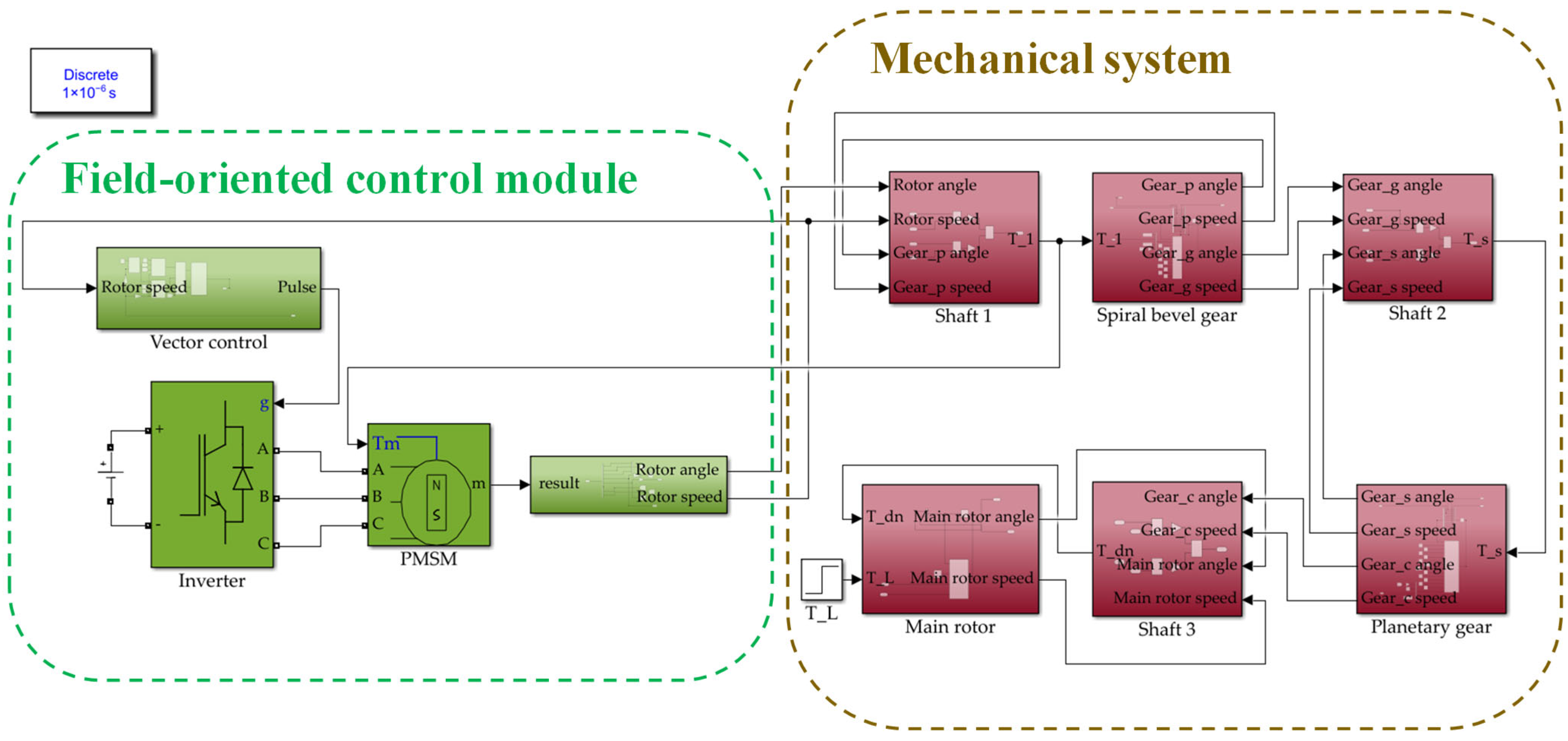
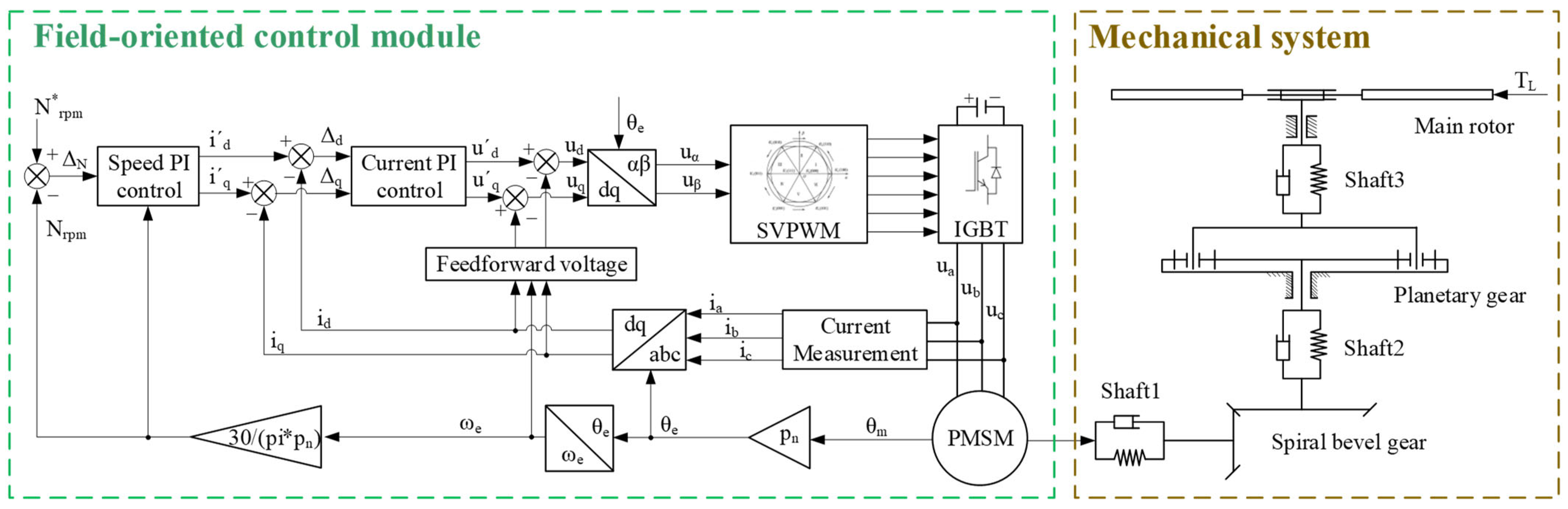
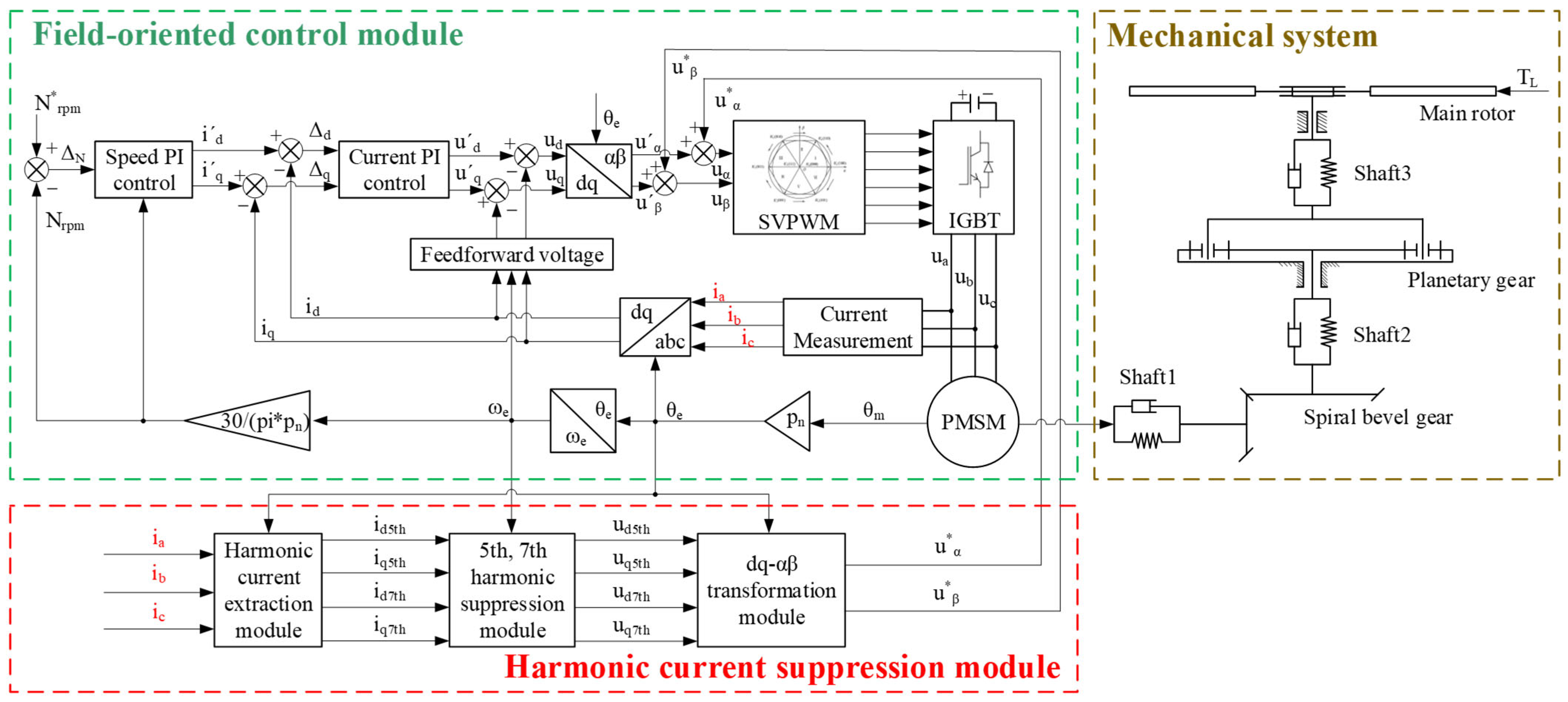
To verify the correctness of the coupling among the subsystems, a simulation and analysis were conducted in MATLAB/Simulink(MATLAB R2022b). It is important to note that in this section, inverter non-idealities such as dead time and voltage drop were not included in the model. This idealized setting was deliberately chosen to isolate and evaluate the intrinsic mechanical and electromechanical dynamics of the coupled PMSM–gear system, without interference from inverter-induced nonlinear effects. Using the electromechanical coupling model shown in
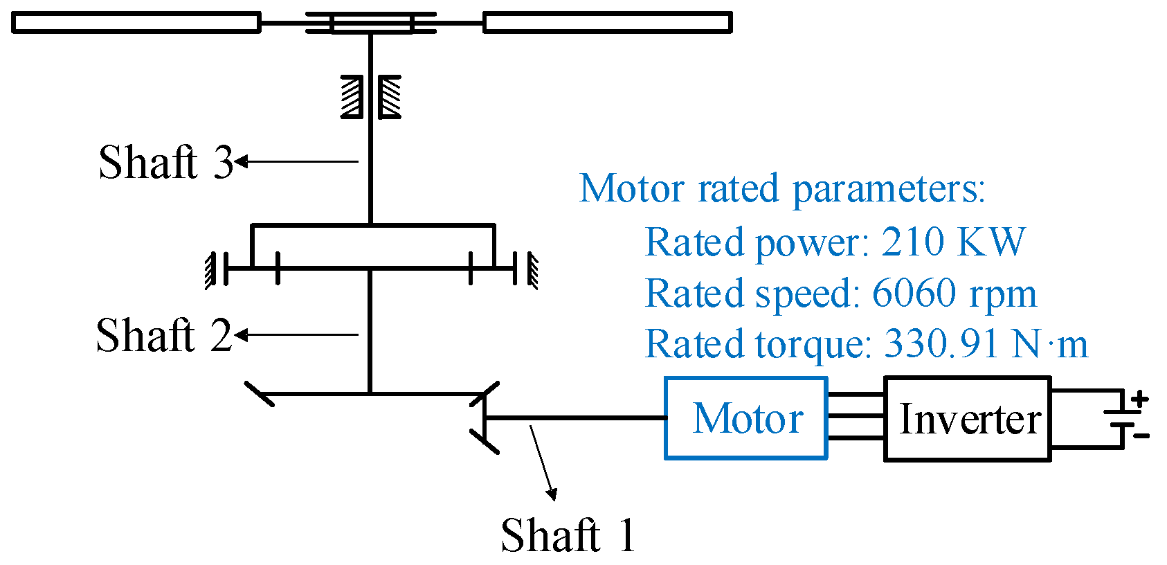
Figure 7, the motor speed was set to 6060 rpm, and the main rotor load torque was set to 5770.6 N·m for the simulation experiment. The frequency characteristics of the EPS were investigated by calculating the characteristic frequencies of the electromechanical coupling model (
Table 3).
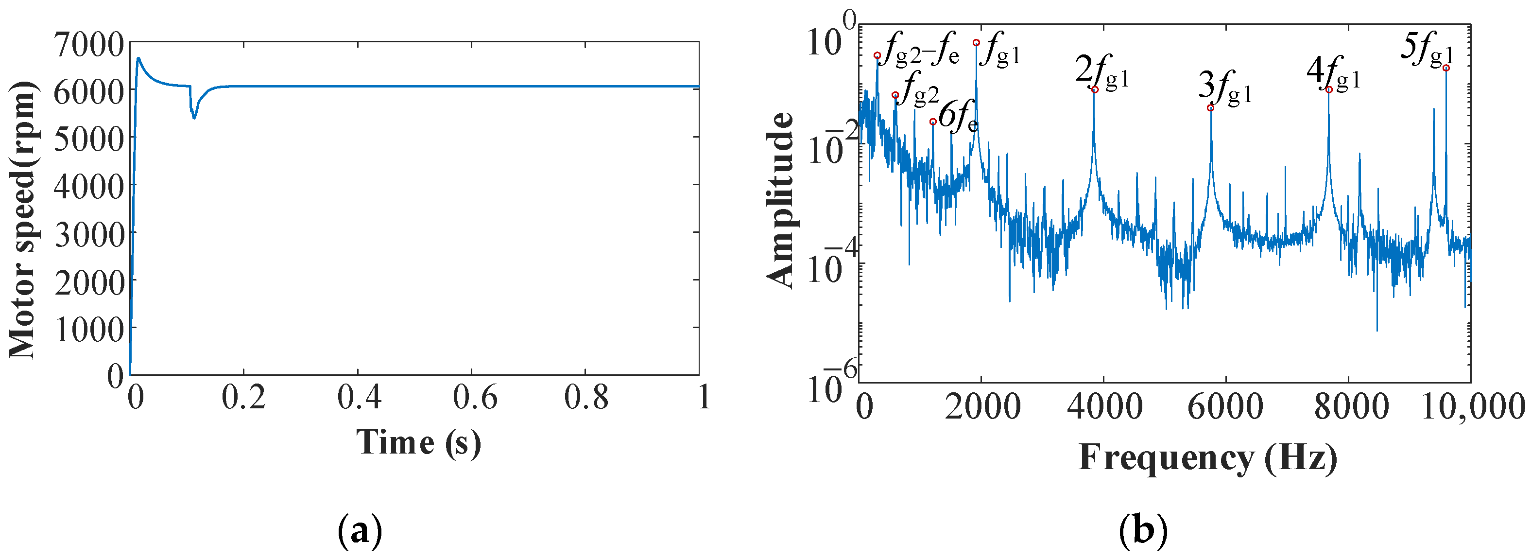
The time-domain and frequency-domain results of the motor speed are presented in
Figure 8. The time-domain results show that during the no-load startup phase, the motor speed exhibits a certain degree of overshoot. This overshoot can be attributed to the controller’s dynamic response and the motor’s rotor inertia. When the rated load is applied at 0.1 s, a sudden drop in speed occurs due to the abrupt increase in load torque, followed by recovery as the speed control system stabilizes the motor. Therefore, the steady-state speed during the 0.3 to 1 s interval was selected for spectral analysis. In addition to the 6th harmonic component of the power supply fundamental frequency (
fe), the meshing frequencies generated by the gear system (
fg1,
fg2) and their higher harmonics can also be observed. The spectral results indicate that vibration components from the gear transmission system are transmitted backward to the motor rotor, suggesting a coupled dynamic interaction between the motor and the gear system.
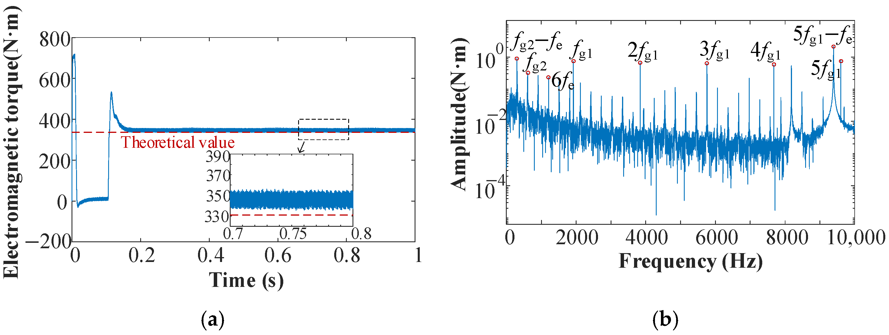
Figure 9 presents the time-domain and frequency-domain results for the motor’s electromagnetic torque. In the time domain, the transient torque response exhibits a rapid rise and a slight overshoot during startup. This corresponds to the early acceleration phase shown in
Figure 8, where a relatively large amount of electromagnetic torque is generated to quickly drive the mechanical system toward the rated speed. This behavior reflects the coordinated response of the controller and the motor under no-load conditions. In the steady-state phase, the actual electromagnetic torque is slightly higher than its theoretical value (calculated as the helicopter main rotor load, divided by the main reducer transmission ratio). This deviation is primarily due to mechanical damping in the main reducer, which requires the motor to deliver slightly more torque to maintain a constant speed. The frequency-domain analysis reveals additional harmonics beyond the 6th harmonic of the power supply’s fundamental frequency (
fe), including the meshing frequencies of the gear transmission system (
fg1,
fg2) and their higher-order harmonics. This indicates that the meshing excitations from the gear system are transmitted to the motor’s electromagnetic torque, further confirming the physical coupling between the mechanical and electrical subsystems.
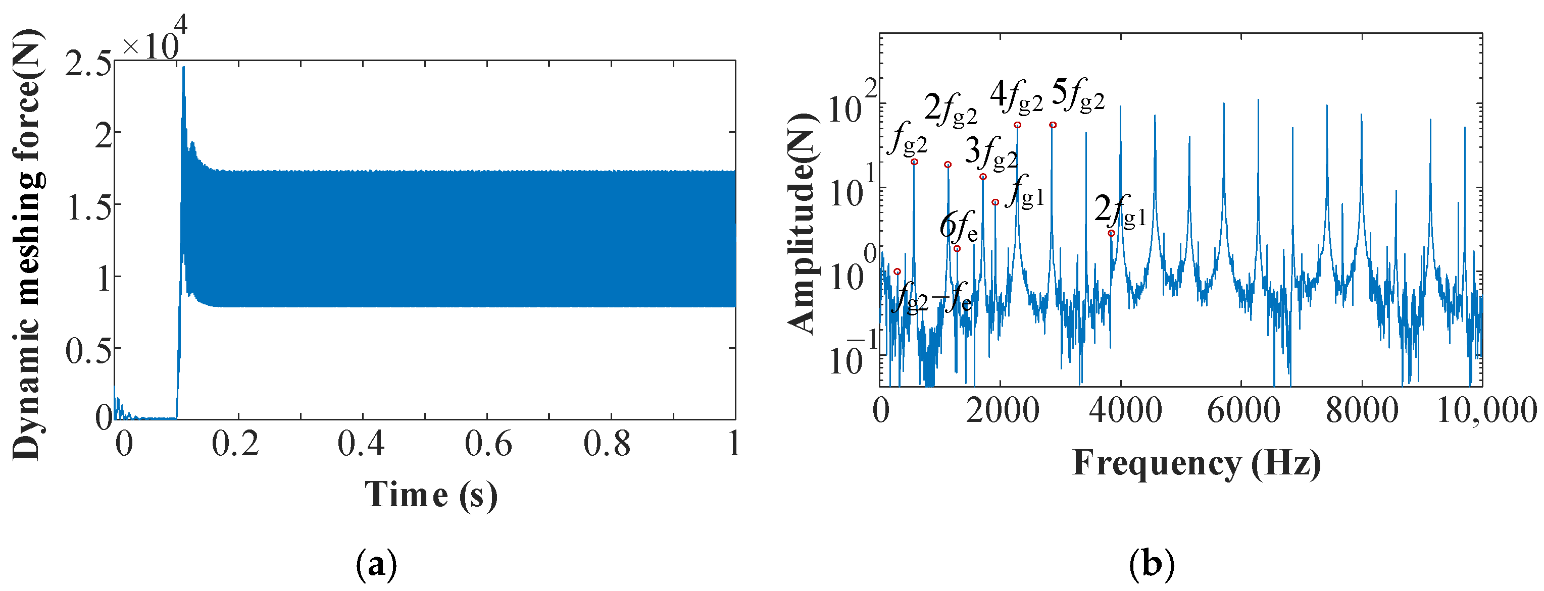
Figure 10 and
Figure 11 show the dynamic responses of the first-stage spiral bevel gear and the second-stage planetary gear set, respectively. No tooth disengagement occurred during steady-state meshing, and the dynamic load coefficients of the two-stage gear transmission were 1.38 and 1.37, respectively (as shown in
Figure 10a and
Figure 11a), indicating moderate dynamic amplification due to meshing stiffness variation and inertial effects during operation. Although the dynamic responses are generally similar, the slightly higher dynamic load coefficient observed in the first stage cannot be attributed to a single deterministic cause. In fact, gear transmission systems represent complex multiple-degree-of-freedom nonlinear dynamic systems. The dynamic meshing force is influenced by the excitation frequency relative to multiple system natural frequencies, vibration mode shapes, and variations in system parameters such as mesh stiffness and damping. Even for the same gear pair, changes in rotational speed or load can increase or decrease dynamic amplification, depending on proximity to resonance regions.
Additionally,
Figure 10b and
Figure 11b indicate that, alongside the meshing frequency components (
fg1,
fg2), the 6th harmonic of the current (
fe)—originating from the electromagnetic torque ripple induced by the inverter-fed PMSM drive—is also present. The coexistence of mechanical and electrical frequency components in the gear force responses confirms the electromechanical coupling mechanism modeled in this study.
The aforementioned analysis confirms that the meshing excitation of the gear system and the electromagnetic torque ripple of the PMSM are coupled. The characteristic frequencies of the mechanical and electrical subsystems are superimposed, validating the accuracy of the established electromechanical coupling model.
4. Vibration Suppression Through Harmonic Current Modulation
In this section, inverter non-idealities—specifically, dead time and voltage drop—are explicitly introduced into the dynamic model to investigate their influence on current distortion and electromagnetic torque fluctuations. The dead time (Td) and voltage drop of the inverter are critical non-ideal factors influencing current waveform fidelity. In the model, it is assumed that the dead time Td = 4 μs, which introduces a deliberate delay between complementary switch transitions to prevent shoot-through. This delay distorts the output voltage by truncating pulse edges. Meanwhile, the conduction voltage drop Vce of the IGBT is set to 3 V, and the forward conduction voltage drop Vd of the diode is 2 V. These combined effects generate periodic discontinuities in the stator current waveform.
4.1. Principle of Vibration Reduction Through Harmonic Current Modulation
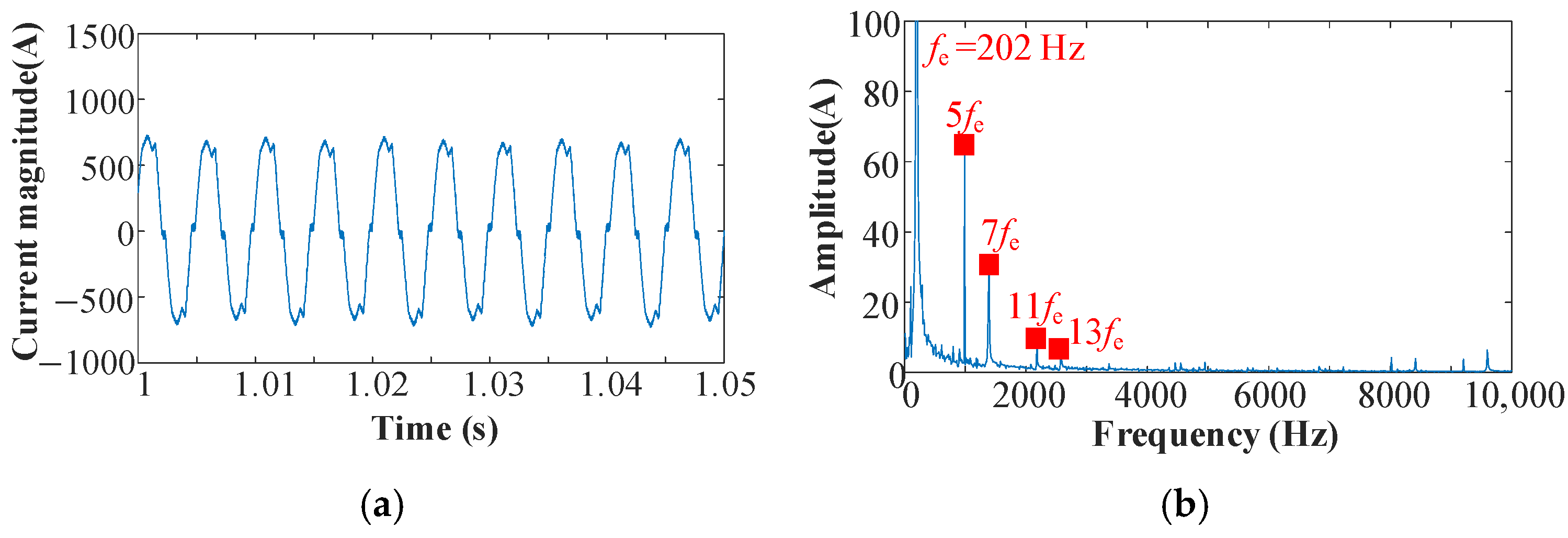
Nonlinear factors, such as dead time and voltage drop in the inverter, cause the stator current to deviate from an ideal sine wave, as shown in
Figure 12a. Frequency spectrum analysis reveals not only the fundamental frequency component (
fe) related to the electrical angular velocity but also higher-order harmonics, such as the 5th, 7th, and 11th, as illustrated in
Figure 12b.
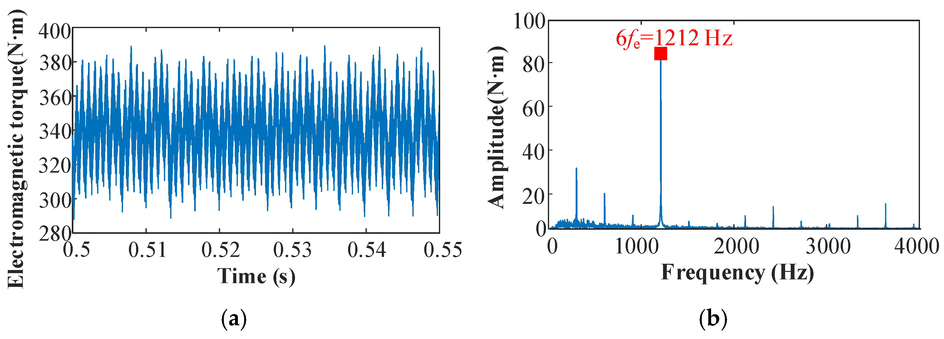
In the stationary three-phase coordinate system, the 5th harmonic current rotates in the opposite direction from the fundamental current, whereas the 7th harmonic current rotates in the same direction [
26]. In the d-q coordinate system, which rotates synchronously with the fundamental current, the rotational speeds of the 5th and 7th harmonics are −6ωe and 6ωe, respectively. This gives rise to the 6th-order high harmonic in the electromagnetic torque (
Figure 13).
This study focuses on the 5th and 7th harmonics of the stator current and establishes the corresponding mathematical models. According to the findings presented in Equation (1), the steady-state voltage equation of the PMSM is as follows:
Let
u*
d =
ud,
u*
q =
uq −
uψ; substituting them into Equation (13), we can obtain:
In the event that the three-phase voltage of the PMSM contains the 5th and 7th harmonics, the d- and q-axis current equations with harmonics subsequent to coordinate transformation are as follows:
where
i1,
i5, and
i7 are the fundamental current, 5th, and 7th harmonic currents, respectively.
θ5 and
θ7 are the initial phases of the 5th and 7th harmonic currents, respectively.
Substituting Equation (15) into Equation (14), the voltage equations with harmonics on the d- and q-axes can be obtained as follows:
According to the abc/dq transformation principle, if the speed and direction of the d–q frame match a harmonic component, that harmonic appears as a DC component in the d–q frame. For instance, if the frame rotates at 5 times the fundamental frequency, the 5th harmonic becomes a DC component. The corresponding steady-state voltage equations are as follows:
where
id5th and
iq5th are the current components in the d–q frame rotating synchronously with the 5th harmonic.
Similarly, the steady-state voltage equation of the 7th harmonic current is as follows:
where
id7th and
iq7th are the current components in the d–q frame rotating synchronously with the 7th harmonic.
Based on the aforementioned mathematical model, to bring the motor current closer to a sine wave and suppress the 6th harmonic in the electromagnetic torque, thereby achieving the torsional vibration suppression of harmonic current modulation, the design objective equation is as follows:
4.2. Torsional Vibration Suppression Strategy of Harmonic Current Modulation
To suppress torsional vibrations via harmonic current modulation, as described by Equations (17)–(19), a harmonic current suppression module can be integrated into the electromechanical coupling model shown in
Figure 7. This module, illustrated in
Figure 14, is capable of the real-time monitoring of harmonic currents in the three-phase currents
ia,
ib, and
ic, and of adjusting the voltage promptly to suppress the 5th and 7th harmonic components.
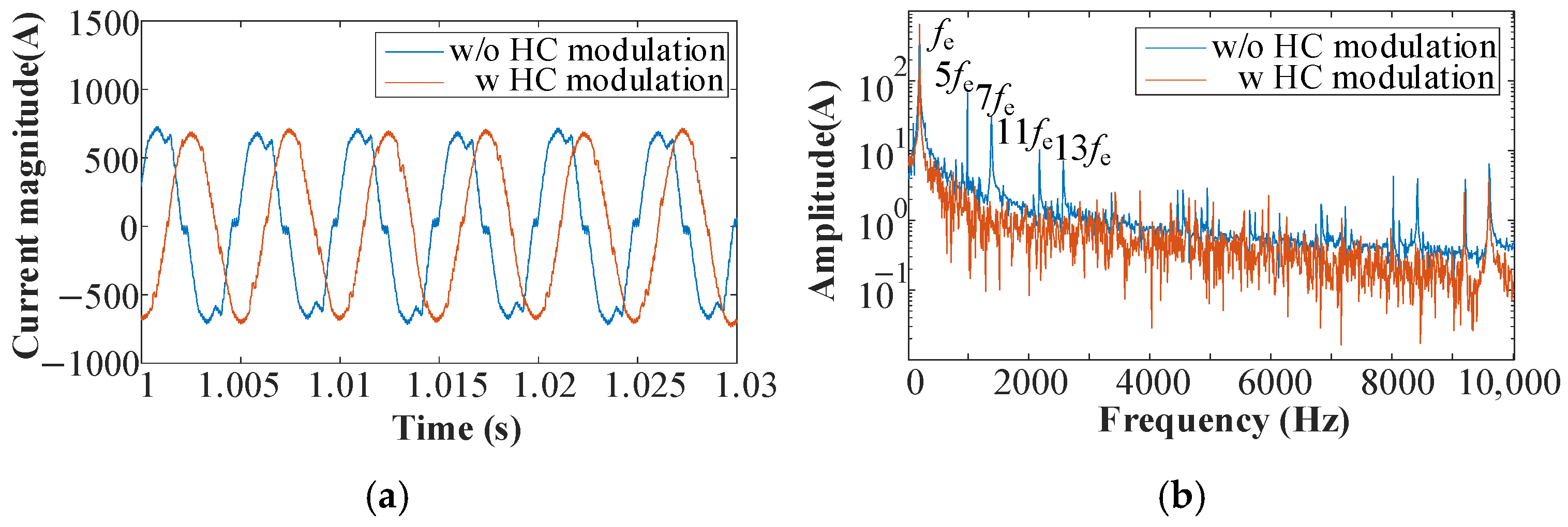
The application of harmonic current suppression (with HC modulation) improves the sinusoidality of the stator current in the steady state, as shown by the red curve in
Figure 15. The FFT analysis reveals the significant suppression of higher-order harmonics, including the 5th, 7th, 11th, and 13th harmonics of the current. Simultaneously, the electromagnetic torque ripple is reduced, with a substantial reduction in the 6th harmonic component (
Figure 16).
To further illustrate this effect, the influence of harmonic current modulation on the mechanical system was analyzed using the first-stage gear transmission as an example. Prior to the application of harmonic current modulation (without HC modulation), the dynamic meshing force exhibited substantial fluctuations, with a dynamic load coefficient of approximately 1.44 (
Figure 17; calculated as the ratio of the peak dynamic meshing force to the static transmission force). After applying harmonic current modulation (with HC modulation), the peak dynamic meshing force was reduced by approximately 500 N, and the dynamic load coefficient decreased to approximately 1.38, corresponding to a 4.17% reduction (calculated as (1.44 − 1.38)/1.44 × 100%). FFT analysis further confirmed that the 6th harmonic was significantly suppressed, with its amplitude reduced from 48.1 to 5.7, a decrease of 88.15%. Additionally, the amplitudes of the gear meshing frequency and its harmonics were reduced to varying extents.
These results demonstrate that harmonic current modulation can effectively suppress the torsional vibrations induced by electromechanical coupling. The noticeable reduction in the dynamic load coefficient indicates an improvement in load uniformity and reduced mechanical stress on the gear teeth. The substantial attenuation of the 6th harmonic also confirms the suppression of torque ripple caused by inverter-fed drive systems. This not only enhances the stability of gear transmission under steady-state conditions but also implies potential benefits for fatigue life and noise reduction. The findings validate the feasibility of the proposed control strategy for improving the dynamic performance and reliability of electric propulsion systems in aerospace applications.
4.3. Analysis of Torsional Vibration Suppression Through Harmonic Current Modulation Under Unsteady Working Conditions
In the practical operation of electromechanical systems, unsteady-state conditions, such as sudden load changes and variable-frequency speed regulation, often induce complex electromechanical coupling effects. The time-varying electromagnetic excitation generated during transient processes significantly influences the torsional vibration of the mechanical transmission system. In this study, the transient vibration characteristics of an electromechanical coupling model with harmonic current suppression were analyzed. Accordingly, torsional vibration suppression under non-stationary operating conditions was investigated using harmonic current modulation. Two scenarios were examined: (1) a sudden load change, simulating gusts of wind acting on a helicopter, and (2) variable-speed operation, simulating helicopter flight dynamics.
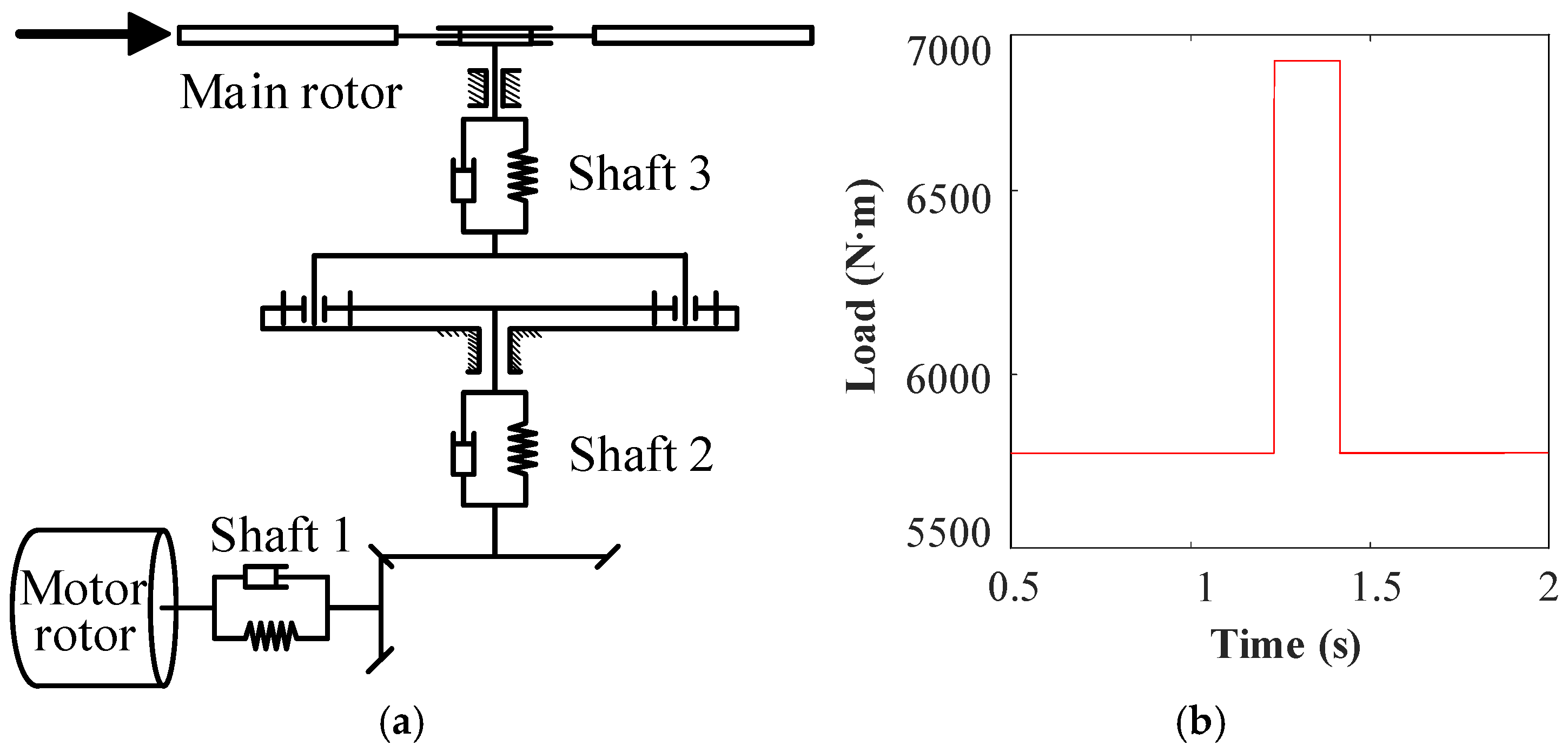
In Scenario 1, an impulse load with an amplitude of 1100 N·m was applied to the main rotor (
Figure 18). The dynamic responses of Shafts 1 and 3 to this sudden load were analyzed.
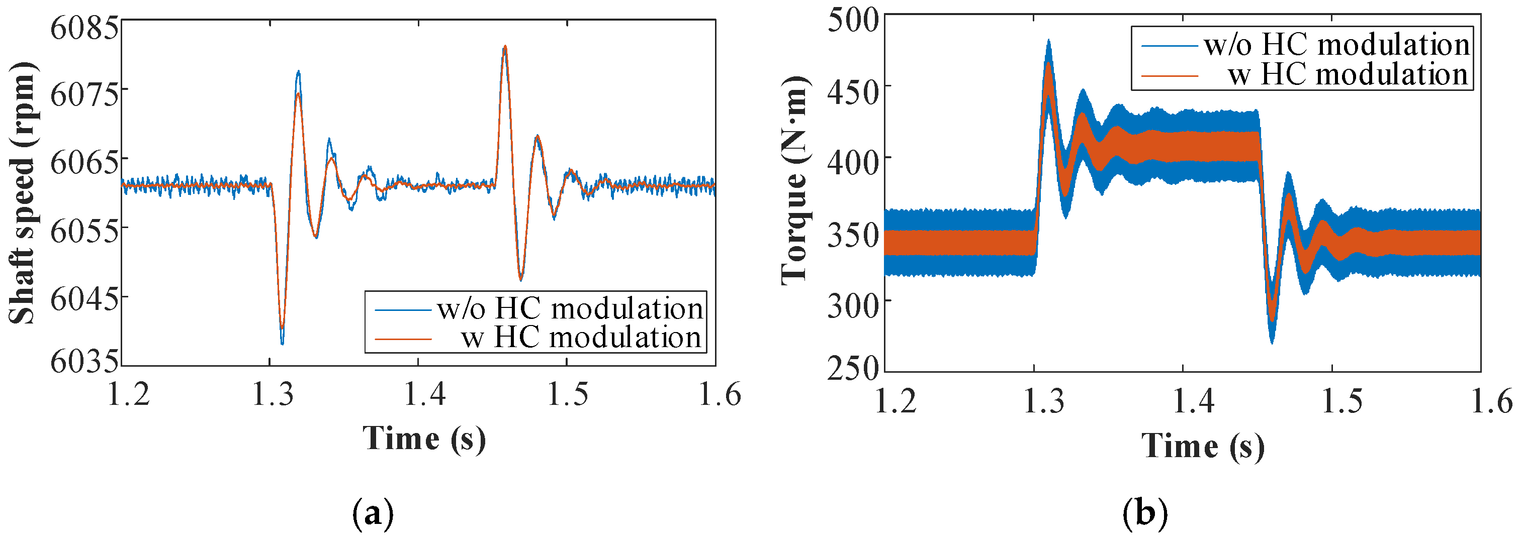
First, the rotational speed and torque at the high-speed input end were compared. In the system using harmonic current modulation, the torsional vibration amplitude of the motor rotor was notably reduced, especially during the stage of load suddenly increased (
Figure 19a). Additionally, the peak torque of Input Shaft 1 was reduced by 15 N·m, as depicted in
Figure 19b. This reduction enhances system safety.
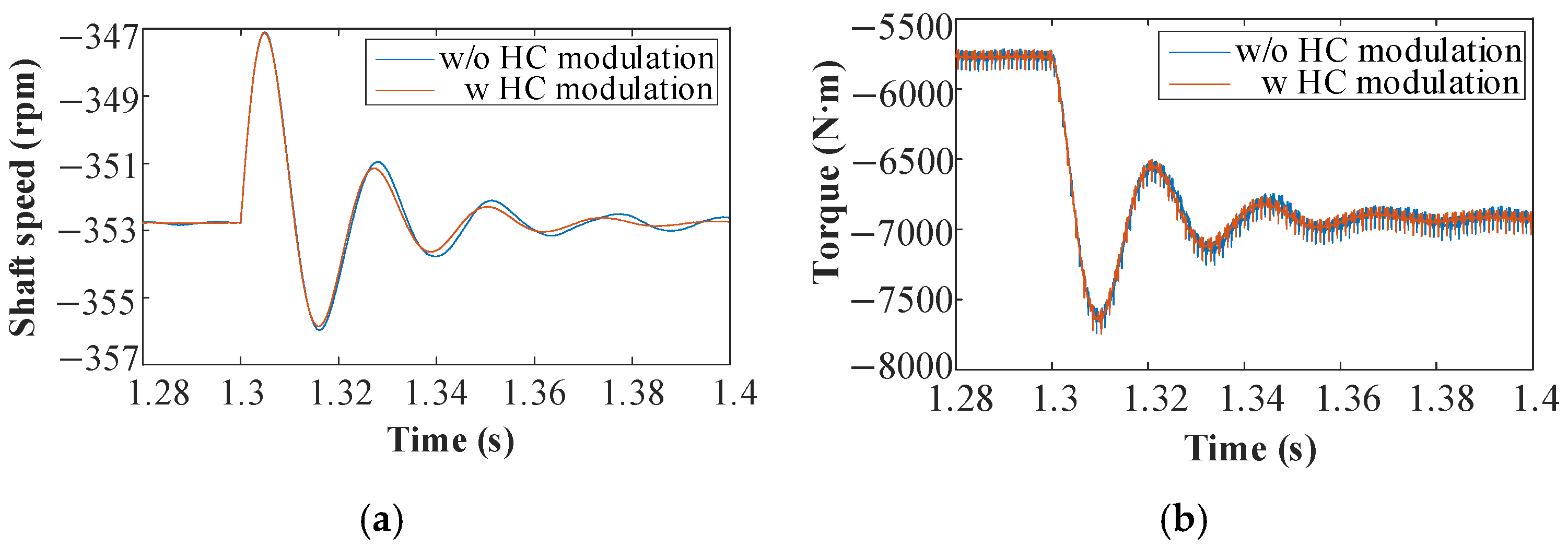
Next, the rotational speed and torque at the low-speed output end were compared. With harmonic current modulation, the main rotor was able to regain a stable rotational speed more quickly after the impact load (
Figure 20a), an advantage for improving flight control stability. However, the peak torque at the output end remained largely unchanged (
Figure 20b). This is likely because the low-speed stage is predominantly influenced by rotor load, and the vibration suppression effect of harmonic current modulation, a high-frequency control technique, is significantly attenuated after passing through two gear transmission stages.
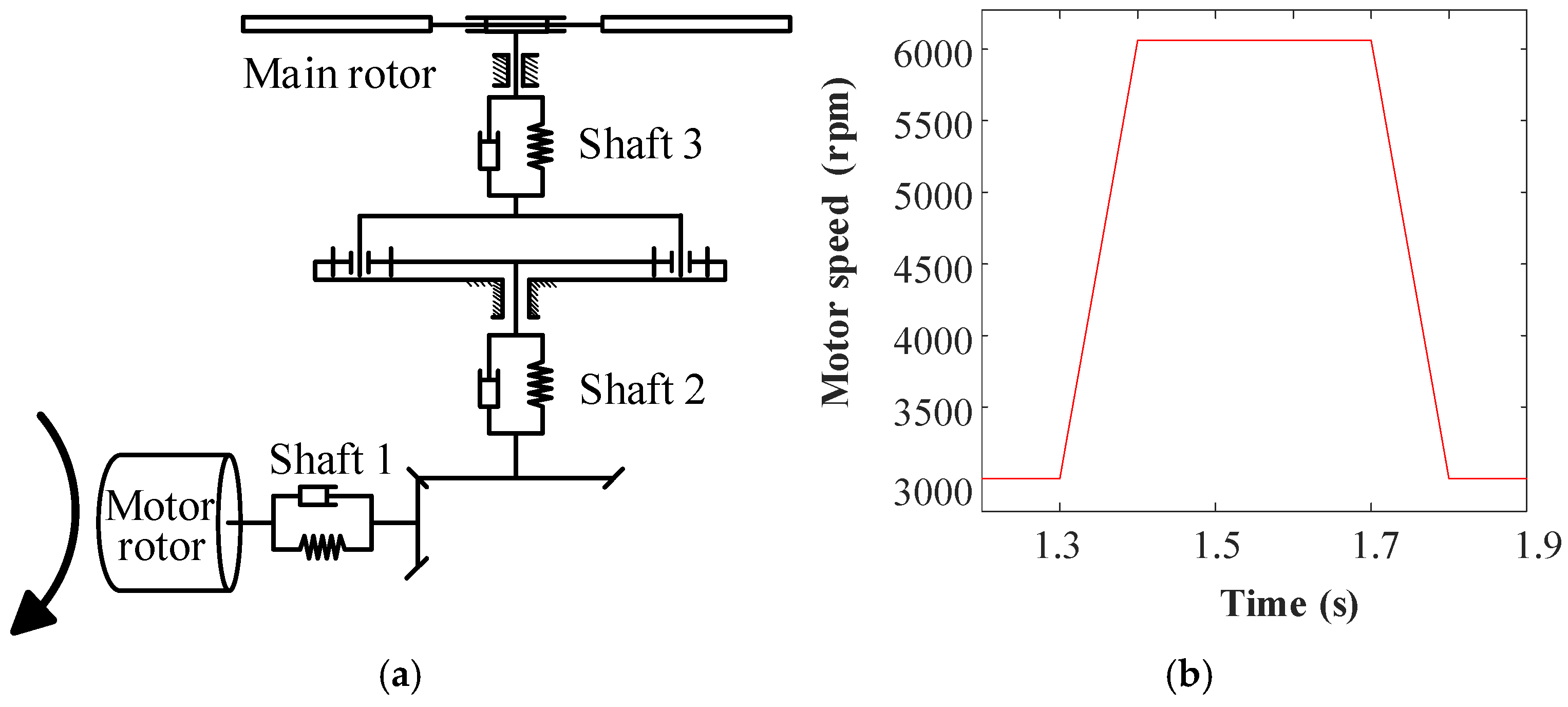
Conventional helicopters are constrained by the dynamic characteristics of the rotor and the rigidity limitations of the power system; therefore, they typically employ a fixed-speed rotor design. The operating speed of the main rotor is usually limited to within ±2% of the reference value. However, this fixed-speed approach restricts the ability to optimize aerodynamic performance across varying flight conditions, such as hovering and high-speed flight. To overcome this limitation, variable-speed rotor systems have been developed. These systems enable the optimization of aerodynamic performance, noise reduction, and energy management by actively adjusting the main rotor speed. Thus, Scenario 2 was designed to evaluate the torsional vibration characteristics of the EPS under variable-speed operation, with a focus on the impact of harmonic current modulation on the transmission system.
In Scenario 2, the motor speed increased from 3000 rpm to 6060 rpm between 1.3 s and 1.4 s, then decreased back to 3000 rpm between 1.7 s and 1.8 s, as shown in
Figure 21. Additionally, the correlation between rotor load and rotor speed was considered using the following empirical relationship [
27]:
where
is the mean value of rotor load and
is the mean value of rotor speed.
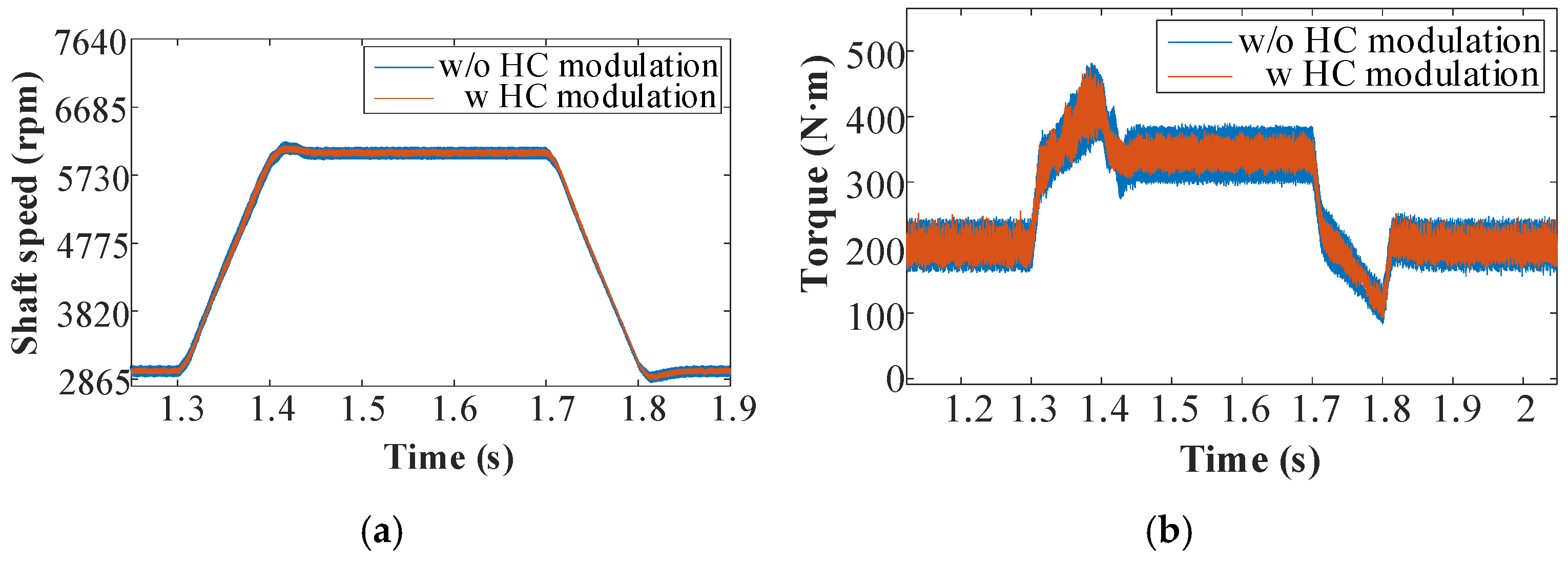
Figure 22 shows the dynamic responses of speed and torque at the high-speed input end. With harmonic current modulation, the speed overshoot after acceleration is reduced, and the rotor reaches the target speed of 6060 rpm more quickly (
Figure 22a). In
Figure 22b, during both acceleration and deceleration, inertia causes overshoot at 1.4 s and 1.8 s. However, the system rapidly stabilizes, and the torque amplitude is reduced by approximately 17 N·m.
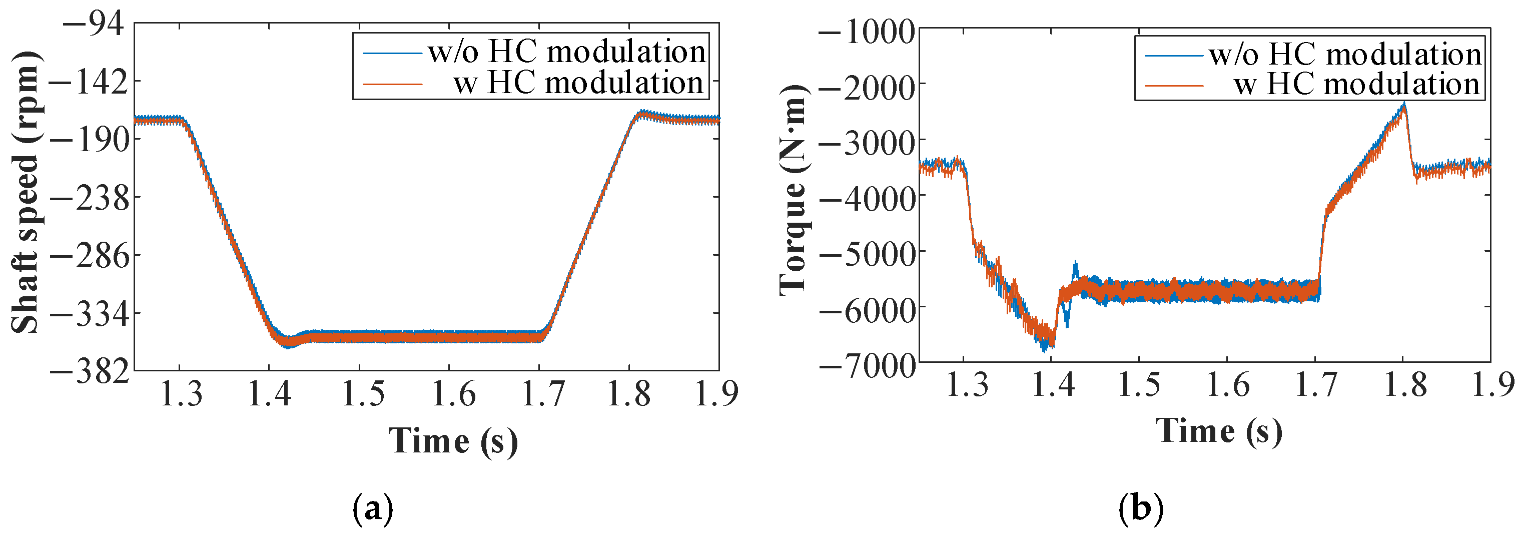
Figure 23 presents the dynamic responses of speed and torque at the low-speed output end. The output end exhibits a similar fluctuation trend to the input end. During acceleration and deceleration, the system with harmonic current modulation shows a faster response and lower torque amplitude.
A comprehensive analysis of both these unsteady-state conditions confirms that harmonic current modulation has a significant effect on transient vibration behavior. Specifically, during sudden changes in speed or load, the modulation strategy effectively reduces torsional overshoot and accelerates the attenuation of vibration amplitudes. These findings suggest that active harmonic current modulation not only improves transient response performance but also enhances system robustness under operational disturbances, which is critical for the reliable operation of electric propulsion systems in aerospace environments.


