
Design and Analysis of a Serial Position-Controlled Variable Stiffness Rotating Mechanism Based on Multi-Stage Torsional Compliant Mechanisms


Abstract
1. Introduction
2. Design Optimization of Compliant Mechanism with Different Shaped Flexures
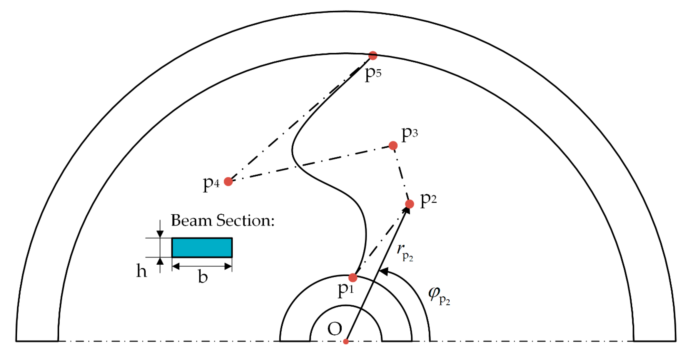
2.1. Formulation of Optimization Problem
2.2. Optimum Design of the Compliant Mechanism
3. Structural Design of the Compliant Actuation Mechanism
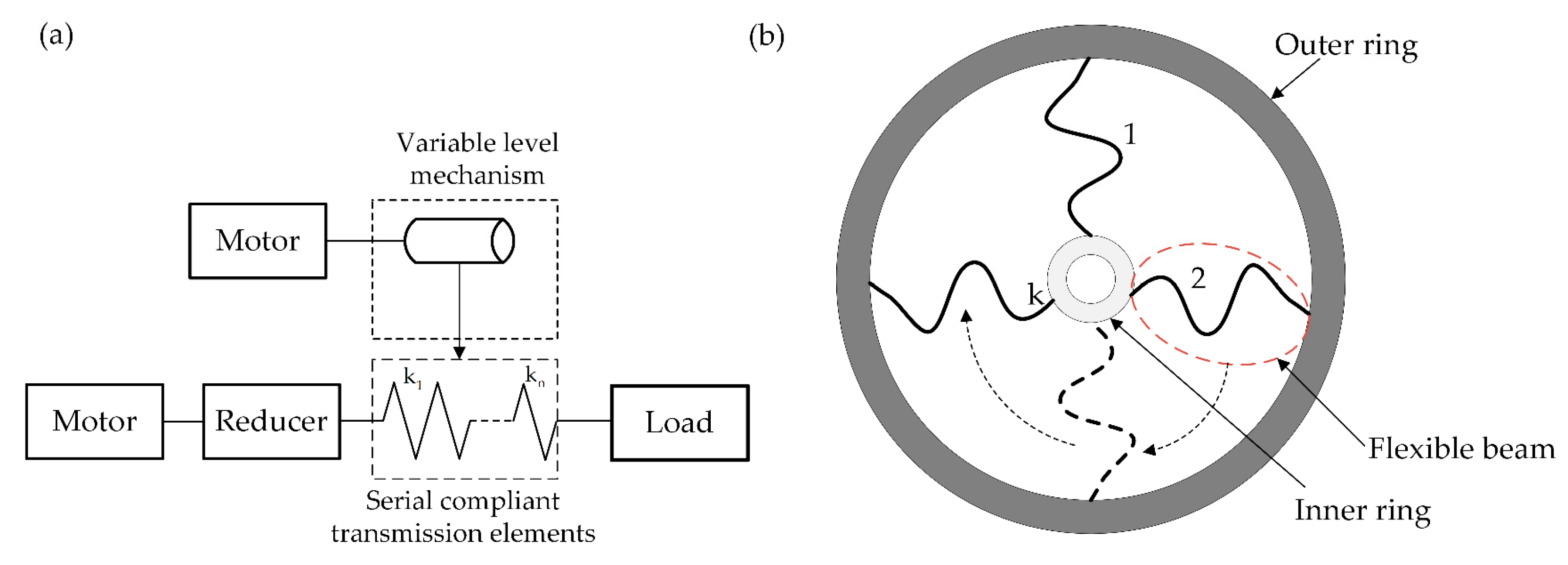
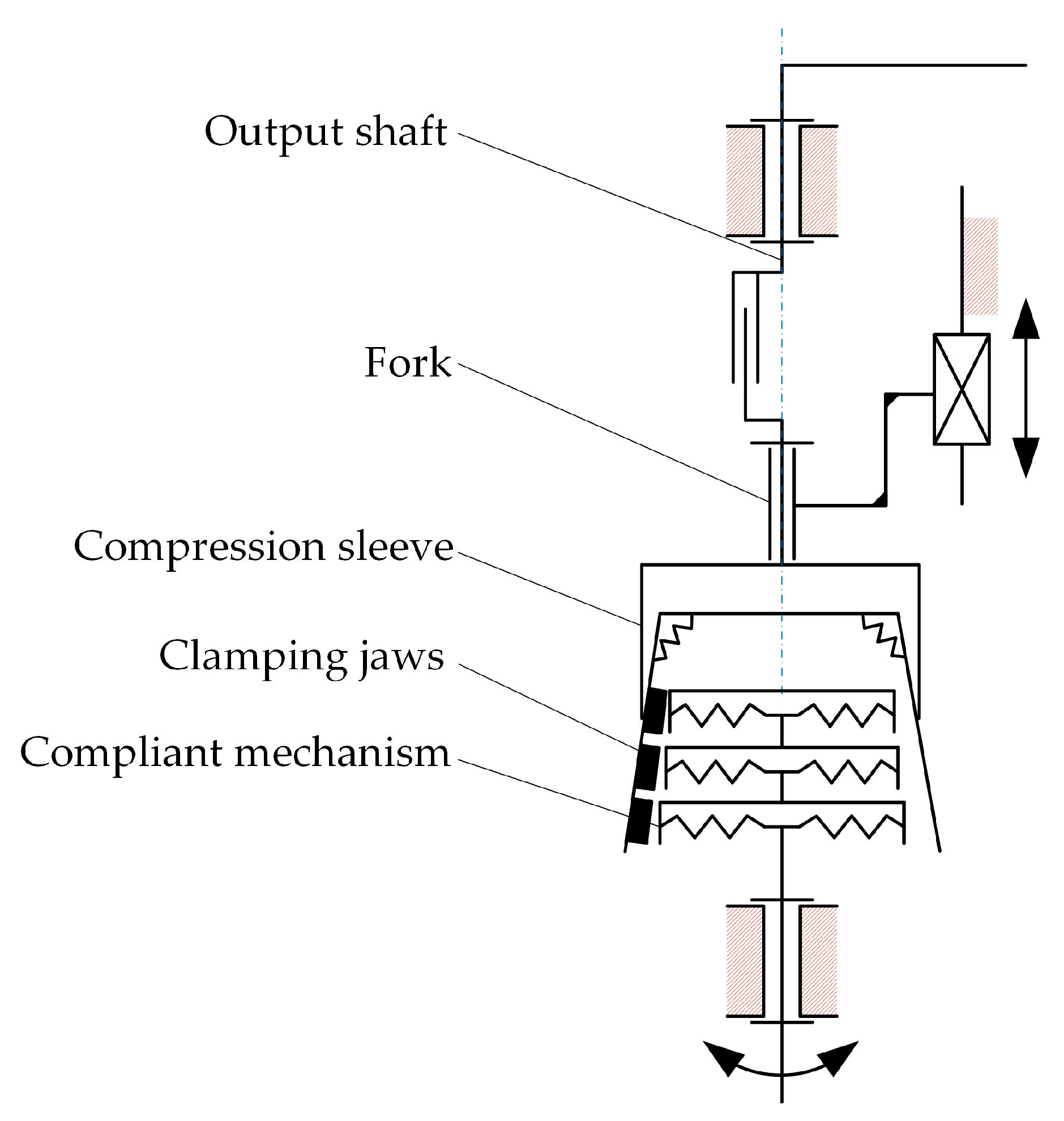
3.1. Working Principle
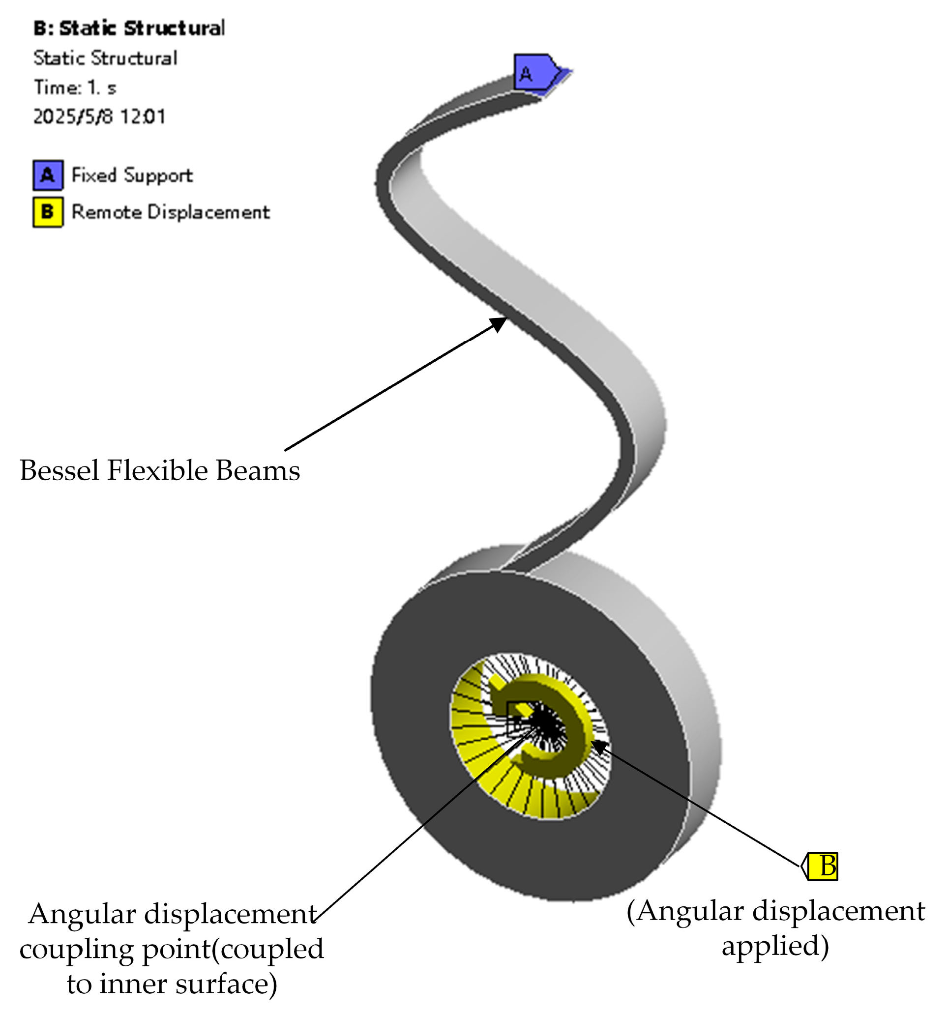
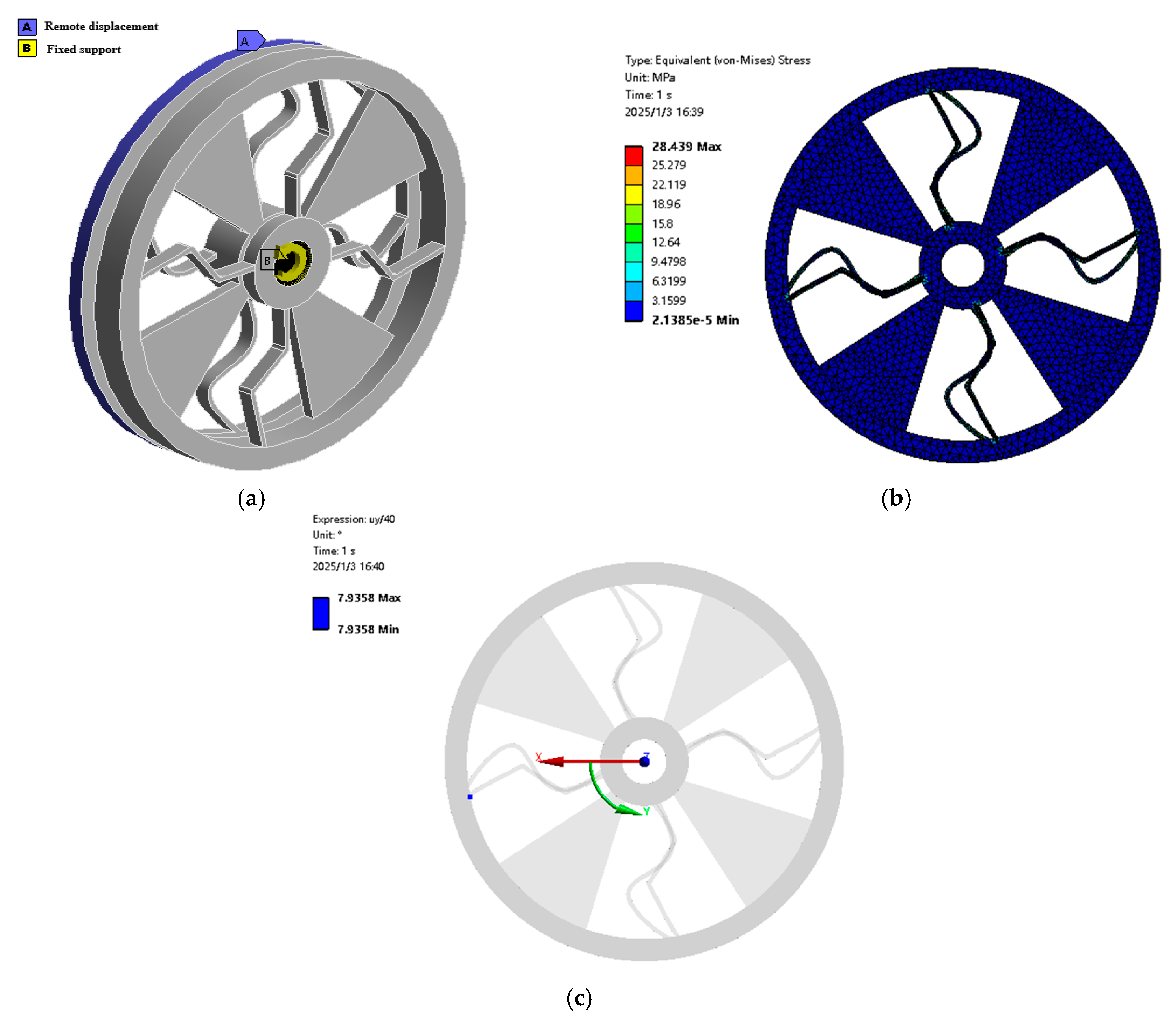
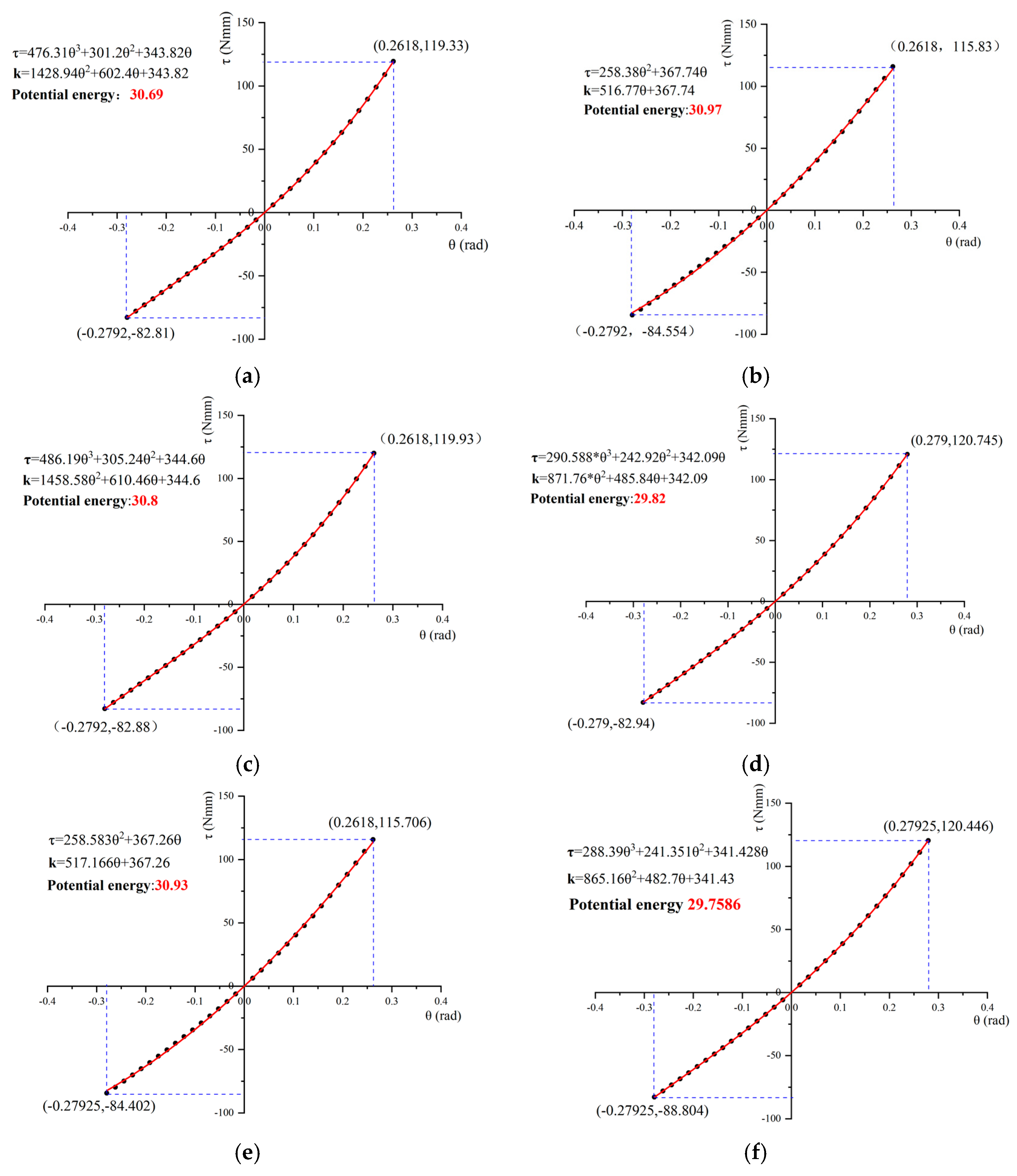
3.2. Finite Element Evaluation of Multi-Stage Compliant Mechanisms
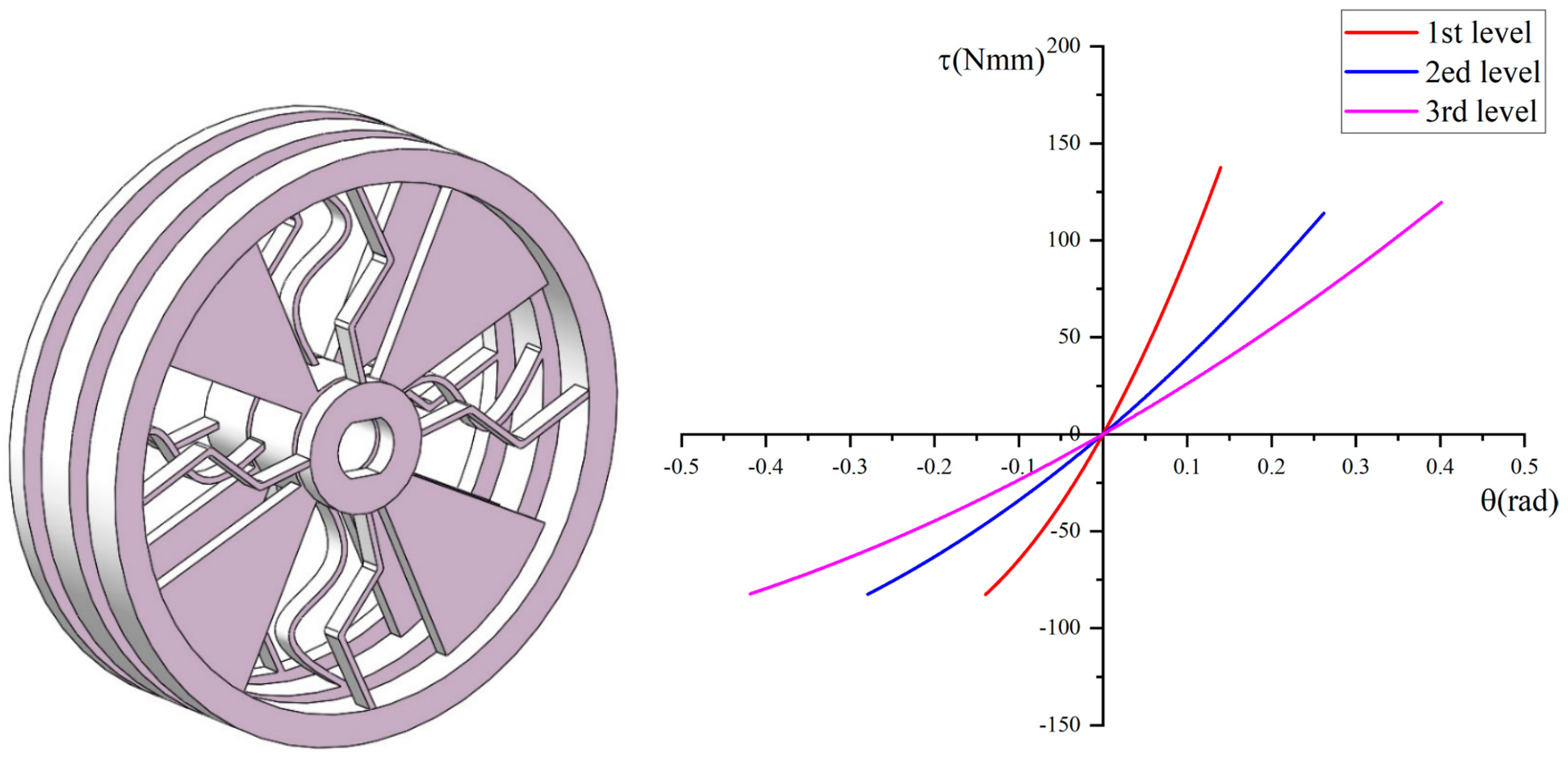
3.3. Strcuture of Variable Stiffness Mechanism
4. Experimental Verification of the Mechanism
5. Results Discussion
6. Conclusions
Author Contributions
Funding
Data Availability Statement
Conflicts of Interest
References
- Villani, V.; Pini, F.; Leali, F.; Secchi, C. Survey on Human-Robot Collaboration in Industrial Settings: Safety, Intuitive Interfaces and Applications. Mechatronics 2018, 55, 248–266. [Google Scholar] [CrossRef]
- Heyer, C. Human-Robot Interaction and Future Industrial Robotics Applications. In Proceedings of the 2010 IEEE/RSJ International Conference on Intelligent Robots and Systems, Taipei, Taiwan, 18–22 October 2010; pp. 4749–4754. [Google Scholar]
- Brogårdh, T. Present and Future Robot Control Development—An Industrial Perspective. Annu. Rev. Control 2007, 31, 69–79. [Google Scholar] [CrossRef]
- Kim, Y.; Kim, D.-W.; Kang, B.-Y. Table-Balancing Cooperative Robot Based on Deep Reinforcement Learning. Sensors 2023, 23, 5235. [Google Scholar] [CrossRef] [PubMed]
- Alvi, M.H.; Fu, J.; Newell, B.A.; Gan, D. A Variable Stiffness Soft Actuator for Hand Rehabilitation. In Proceedings of the 2024 6th International Conference on Reconfigurable Mechanisms and Robots (Remar), Chicago, IL, USA, 23–26 June 2024; pp. 587–594. [Google Scholar]
- Du, W.; Yi, G.; Omisore, O.M.; Duan, W.; Oluwadra Akinyemi, T.; Chen, X.; Liu, J.; Lee, B.-G.; Wang, L. Analyzing Surgeon-Robot Cooperative Performance in Robot-Assisted Intravascular Catheterization. IEEE Trans. Hum.-Mach. Syst. 2024, 54, 698–710. [Google Scholar] [CrossRef]
- Li, X.; Hao, Y.; Zhang, J.; Wang, C.; Li, D.; Zhang, J. Design, Modeling and Experiments of a Variable Stiffness Soft Robotic Glove for Stroke Patients with Clenched Fist Deformity. IEEE Robot. Autom. Lett. 2023, 8, 4044–4051. [Google Scholar] [CrossRef]
- Li, Z.; Chu, X.; Hu, X.; Zhang, Z.; Li, N.; Li, J. Variable Stiffness Methods for Robots: A Review. Smart Mater. Struct. 2024, 33, 63002. [Google Scholar] [CrossRef]
- Bilancia, P.; Berselli, G.; Scarcia, U.; Palli, G. Design of a Beam-Based Variable Stiffness Actuator via Shape Optimization in a CAD/CAE Environment. In Proceedings of the ASME 2018 Conference on Smart Materials, Adaptive Structures and Intelligent Systems, San Antonio, TX, USA, 10 September 2018; American Society of Mechanical Engineers: New York, NY, USA, 2018; p. V001T03A013. [Google Scholar]
- Bilancia, P.; Berselli, G.; Palli, G. Virtual and Physical Prototyping of a Beam-Based Variable Stiffness Actuator for Safe Human-Machine Interaction. Robot. Comput.-Integr. Manuf. 2020, 65, 101886. [Google Scholar] [CrossRef]
- Palli, G.; Melchiorri, C.; Berselli, G.; Vassura, G. Design and Modeling of Variable Stiffness Joints Based on Compliant Flexures. In Proceedings of the ASME 2010 International Design Engineering Technical Conferences and Computers and Information in Engineering Conference, Montreal, QC, Canada, 15 August 2010; ASMEDC: Washington, DC, USA, 2010; pp. 1069–1078. [Google Scholar]
- Sun, X.; Xiong, X.; Chen, W.; Chen, W.; Yang, G. Design and Control of a Novel Variable Stiffness Actuator Based on Antagonistic Variable Radius Principle. ISA Trans. 2024, 147, 567–576. [Google Scholar] [CrossRef]
- Xiong, X.; Sun, X.; Chen, W.; Zhi, Y.; Fang, X. Design of a Variable Stiffness Actuator Based on Variable Radius Mechanisms. In Proceedings of the 2022 IEEE/ASME International Conference on Advanced Intelligent Mechatronics (AIM), Sapporo, Japan, 11 July 2022; pp. 1567–1572. [Google Scholar]
- Gaozhang, W.; Li, Y.; Shi, J.; Wang, Y.; Stilli, A.; Wurdemann, H. A Novel Stiffness-Controllable Joint Using Antagonistic Actuation Principles. Mech. Mach. Theory 2024, 196, 105614. [Google Scholar] [CrossRef]
- Ning, Y.; Xu, W.; Huang, H.; Li, B.; Liu, F. Design Methodology of a Novel Variable Stiffness Actuator Based on Antagonistic-Driven Mechanism. Proc. Inst. Mech. Eng. C J. Mech. Eng. Sci. 2019, 233, 6967–6984. [Google Scholar] [CrossRef]
- Zhang, W.; Yan, P. A Variable Stiffness Compliant Actuator Based on Antagonistic Normal-Stressed Electromagnetic Mechanism. Sens. Actuators A 2024, 366, 114983. [Google Scholar] [CrossRef]
- Van Ham, R.; Vanderborght, B.; Van Damme, M.; Verrelst, B.; Lefeber, D. MACCEPA, the Mechanically Adjustable Compliance and Controllable Equilibrium Position Actuator: Design and Implementation in a Biped Robot. Rob. Auton. Syst. 2007, 55, 761–768. [Google Scholar] [CrossRef]
- Vanderborght, B.; Tsagarakis, N.G.; Van Ham, R.; Thorson, I.; Caldwell, D.G. MACCEPA 2.0: Compliant Actuator Used for Energy Efficient Hopping Robot Chobino1D. Auton. Rob. 2011, 31, 55–65. [Google Scholar] [CrossRef]
- Xu, Y.; Guo, K.; Sun, J.; Li, J. Design, Modeling and Control of a Reconfigurable Variable Stiffness Actuator. Mech. Syst. Signal Proc. 2021, 160, 107883. [Google Scholar] [CrossRef]
- Cui, C.; Guo, K.; Sun, J. Variable Stiffness Actuator Structure for Robot. In Intelligent Robotics and Applications, ICIRA 2021, PT I; Liu, X.J., Nie, Z., Yu, J., Xie, F., Song, R., Eds.; Springer International Publishing Ag: Cham, Switzerland, 2021; Volume 13013, pp. 275–283. [Google Scholar]
- Abbood, W.T.; Nacy, S.M.; Youssef, G.; Abdullah, O.I. Dynamic Performance of a Series Elastic Actuator with Variable Stiffness Logarithmic Spiral Spring. Intell. Serv. Rob. 2022, 15, 275–287. [Google Scholar] [CrossRef]
- Jafari, A.; Tsagarakis, N.G.; Caldwell, D.G. A Novel Intrinsically Energy Efficient Actuator with Adjustable Stiffness (AwAS). IEEE/ASME Trans. Mechatron. 2013, 18, 355–365. [Google Scholar] [CrossRef]
- Jafari, A.; Tsagarakis, N.G.; Caldwell, D.G. AwAS-II: A New Actuator with Adjustable Stiffness Based on the Novel Principle of Adaptable Pivot Point and Variable Lever Ratio. In Proceedings of the 2011 IEEE International Conference on Robotics and Automation (ICRA), Shanghai, China, 9 May 2011; pp. 4638–4643. [Google Scholar]
- Lu, Y.; Yang, Y.; Xue, Y.; Jiang, J.; Zhang, Q.; Yue, H. A Variable Stiffness Actuator Based on Leaf Springs: Design, Model and Analysis. Actuators 2022, 11, 282. [Google Scholar] [CrossRef]
- Visser, L.C.; Carloni, R.; Stramigioli, S. Energy-Efficient Variable Stiffness Actuators. IEEE Trans. Robot. 2011, 27, 865–875. [Google Scholar] [CrossRef]
- Ramadan, M.A.; Awad, M.I.; Boushaki, M.N.; Niu, Z.; Khalaf, K.; Hussain, I. irisVSA: Infinite-Rotation Infinite-Stiffness Variable Stiffness Actuator towards Physical Human–Robot-Interaction. Mechatronics 2023, 96, 103095. [Google Scholar] [CrossRef]
- Yi, S.; Liu, S.; Liao, J.; Guo, Z. Design and Modeling of a Compact Serial Variable Stiffness Actuator (SVSA-III) with Linear Stiffness Profile. In Proceedings of the 2024 IEEE International Conference on Robotics and Automation (ICRA), Yokohama, Japan, 13 May 2024; pp. 7077–7082. [Google Scholar]
- Yang, T.; Zhang, H.; Zhang, S.; Wu, X.; Qiu, Y.; Zhang, J. Design and Modeling of a Trapezoidal Leaf Spring-Based Actuators with Valid Arm Length and Bending Deformation for Stiffness Adjustment. In Proceedings of the 2024 3rd Conference on Fully Actuated System Theory and Applications (FASTA), Shenzhen, China, 10 May 2024; pp. 121–126. [Google Scholar]
- Shao, Y.; Shi, D.; Feng, Y.; Zhang, W.; Ding, X. Design and Control of a Compact Variable Stiffness Actuator Based on a Cam-Circular Beam Mechanism. IEEE/ASME Trans. Mechatron. 2024, 29, 4131–4143. [Google Scholar] [CrossRef]
- Yang, Y.; Wang, P.; Zhu, H.; Xia, K.; Ren, T.; Shen, Y.; Li, Y. A Variable Stiffness Soft Robotic Manipulator Based on Antagonistic Design of Supercoiled Polymer Artificial Muscles and Shape Memory Alloys. Sens. Actuators A 2024, 366, 114999. [Google Scholar] [CrossRef]
- Zhu, S.; Liu, M.; Min, X.; Dong, S. Research on Variable Stiffness Robotic Joint Actuator Based on Shape Memory Alloy. J. Mech. Sci. Technol. 2025, 39, 939–948. [Google Scholar] [CrossRef]
- Carloni, R.; Lapp, V.I.; Cremonese, A.; Belcari, J.; Zucchelli, A. A Variable Stiffness Joint with Electrospun P(VDF-TrFE-CTFE) Variable Stiffness Springs. IEEE Robot. Autom. Lett. 2018, 3, 973–978. [Google Scholar] [CrossRef]
- Giraud, F.H.; Mete, M.; Paik, J. Flexure Variable Stiffness Actuators. Adv. Intell. Syst. 2022, 4, 2100282. [Google Scholar] [CrossRef]
- Caro, F.; Carmichael, M.G. A Review of Mechanisms to Vary the Stiffness of Laminar Jamming Structures and Their Applications in Robotics. Actuators 2024, 13, 64. [Google Scholar] [CrossRef]
- Xu, F.; Ma, K.; He, X.; Wei, M.; Hu, C. Design, Analysis, and Testing of a Variable-Stiffness Soft Grabbing Robot Coupling Particle Jamming and Layer Jamming. Smart Mater. Struct. 2024, 33, 55036. [Google Scholar] [CrossRef]
- Arleo, L.; Lorenzon, L.; Cianchetti, M. Variable Stiffness Linear Actuator Based on Differential Drive Fiber Jamming. IEEE Trans. Robot. 2023, 39, 4429–4442. [Google Scholar] [CrossRef]
- Peng, H.; Wang, X.; Geng, D.; Xu, W. A Pneumatic Particle-Blocking Variable-Stiffness Actuator. Sensors 2023, 23, 9817. [Google Scholar] [CrossRef]
- Chen, C.; Ren, H.; Wang, H. Augment Laminar Jamming Variable Stiffness Through Electroadhesion and Vacuum Actuation. IEEE Trans. Robot. 2025, 41, 819–836. [Google Scholar] [CrossRef]
- Mikol, C.; Su, H.-J. An Actively Controlled Variable Stiffness Structure via Layer Jamming and Pneumatic Actuation. In Proceedings of the 2019 International Conference on Robotics and Automation (ICRA), Montreal, QC, Canada, 20–24 May 2019; pp. 7555–7561. [Google Scholar]


| Variable Stiffness Mechanism Design | Advantage | Disadvantages |
|---|---|---|
| Antagonistic design approach | Flexible stiffness adjustment with customizable stiffness | Large volume, complex dual motor coupling cooperative control, flexible element secondary characteristics are difficult to realize |
| Serial design approach | Large stiffness range adjustment, and decoupled position-stiffness motor control | Complex and large-size structure |
| Fabrication by new materials | Compactness the overall mechanism and reduced structural complexity | Expensive and limited application environments |
| Laminar jamming | Large stiffness bandwidth and fast dynamic response | Heavily depends on the use of new materials and technologies with high cost |
| Pneumatic pellet blocking | The bending motion is more natural. | Airbags have a limited lifespan and precise control of air pressure is difficult |
| Electromagnetic | Accurate stiffness adjustment | Synchronous cooperation with other components, complex structure |
| Variables | Initial Value | Lower and Upper Bounds | Optimized Value |
|---|---|---|---|
| 89.41° | [80, 98]° | 84.766° | |
| 53.91° | [45, 70]° | 68.551° | |
| 23.76 mm | [21, 30] mm | 22.944 mm | |
| 69.27° | [62, 76]° | 73.295° | |
| 29.30 mm | [26, 35] mm | 28.926 mm | |
| 126.59° | [113, 139]° | 128.58° | |
| 35.46 mm | [31, 37] mm | 31.897 mm | |
| 88.59° | [79, 97]° | 82.557° |
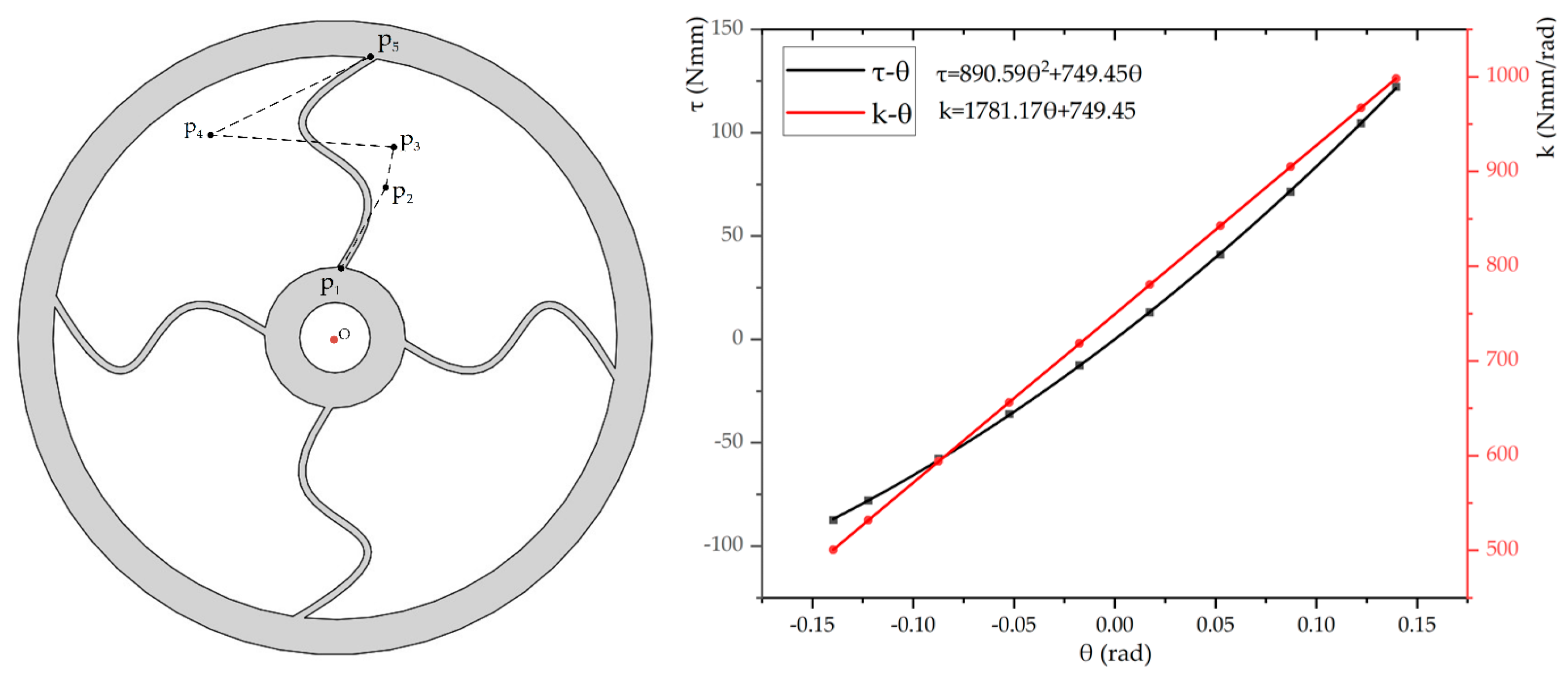
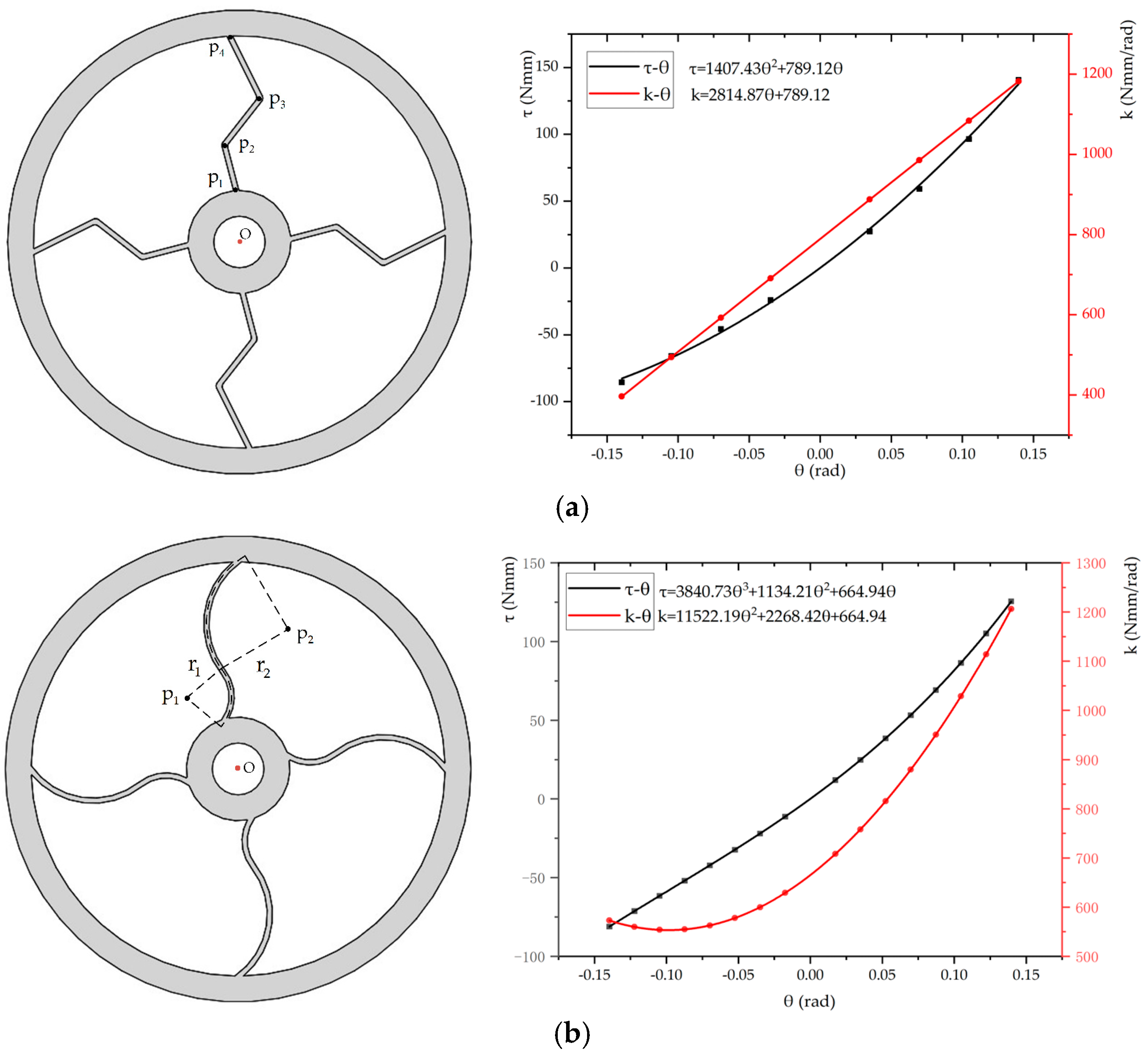
| Flexible Beams | Bezier Curve | Multiple Straight Segments | Two Arc Segments |
|---|---|---|---|
| k [Nmm/rad] | [500.8, 998.1] | [396.16, 1182.07] | [572.8, 1206] |
| [τmin, τmax] [Nmm] | [−87.47, 122.21] | [−85.52, 140.62] | [−81.11, 125.54] |
| Combined Compliant Mechanisms | Lower and Upper Bounds of Elastic Deformation (°) | Stiffness Range (Nmm/rad) | Max Error Between Analytical and Simulation Results (%) |
|---|---|---|---|
| multiple straight and arc segments | [−16, 15] | 287.03~599.47 | 20.58 |
| multiple straight segments and the Bezier curve | [−16, 15] | 223.43~503.03 | 5.38 |
| multiple arc and straight segments | [−16, 15] | 287.87~604.83 | 21.39 |
| multiple arc segments and the Bezier curve | [−16, 16] | 274.40~545.74 | 3.05 |
| the Bezier curve and multiple straight segments | [−16, 15] | 222.84~502.65 | 5.30 |
| the Bezier curve and multiple arc segments | [−16, 16] | 274.10~543.69 | 3.3 |
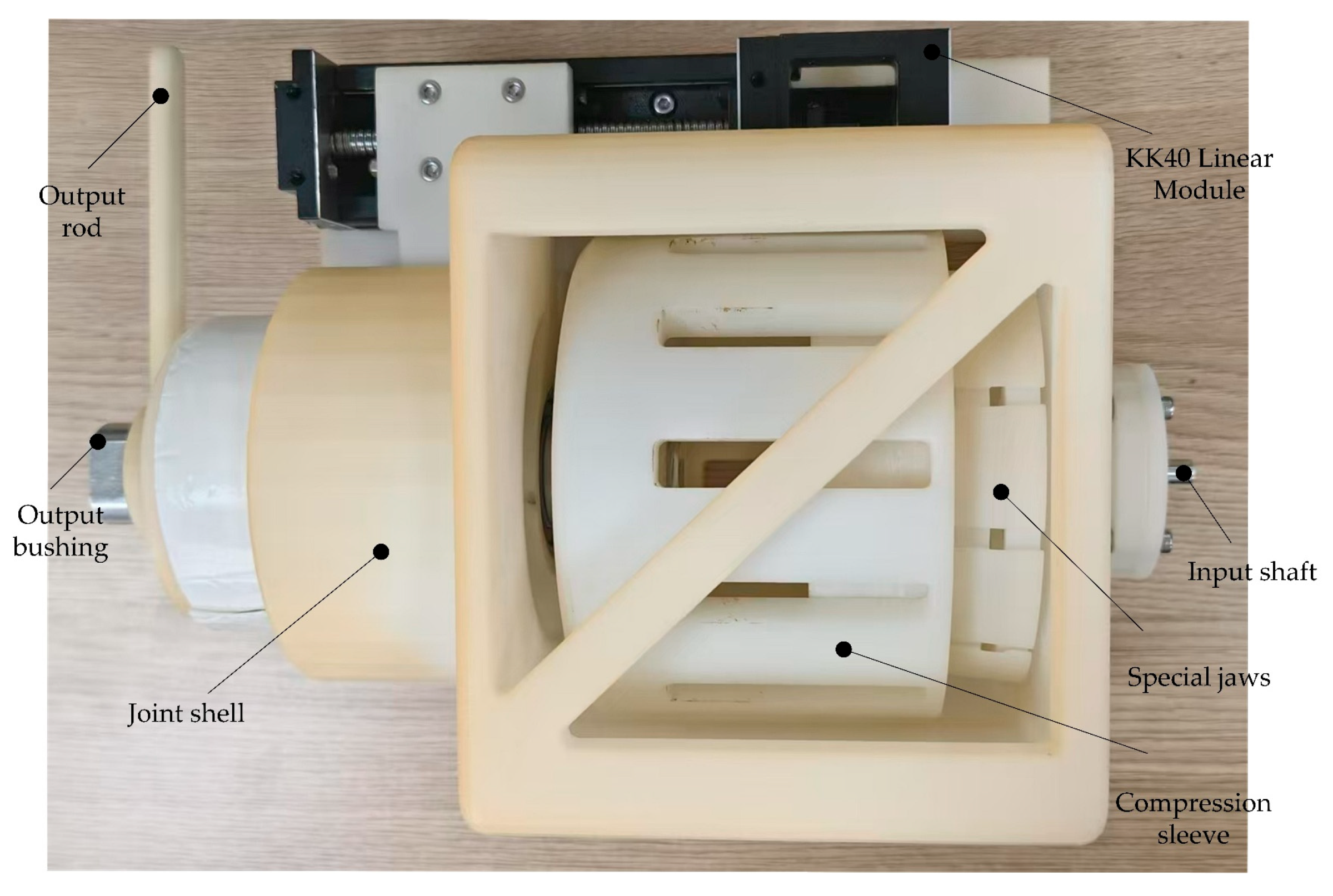
| Components | Functionality |
|---|---|
| Output rod | For torque application and angle reading |
| Output bushing | For torque transmission in connection with the output shaft |
| Joint shell | For fixing parts and observing the position of the compression sleeve |
| KK40 Linear Module | Used for axial movement of the output shaft in conjunction with a fork |
| Input shaft | Used as a fixed end in experiments |
| Special jaws | For clamping the outer ring of flexible components |
| Compression sleeve | For clamping the outer ring of a flexible element with special jaws |
Disclaimer/Publisher’s Note: The statements, opinions and data contained in all publications are solely those of the individual author(s) and contributor(s) and not of MDPI and/or the editor(s). MDPI and/or the editor(s) disclaim responsibility for any injury to people or property resulting from any ideas, methods, instructions or products referred to in the content. |
© 2025 by the authors. Licensee MDPI, Basel, Switzerland. This article is an open access article distributed under the terms and conditions of the Creative Commons Attribution (CC BY) license (https://creativecommons.org/licenses/by/4.0/).
Share and Cite
Wen, K.; Wu, G. Design and Analysis of a Serial Position-Controlled Variable Stiffness Rotating Mechanism Based on Multi-Stage Torsional Compliant Mechanisms. Actuators 2025, 14, 236. https://doi.org/10.3390/act14050236
Wen K, Wu G. Design and Analysis of a Serial Position-Controlled Variable Stiffness Rotating Mechanism Based on Multi-Stage Torsional Compliant Mechanisms. Actuators. 2025; 14(5):236. https://doi.org/10.3390/act14050236
Chicago/Turabian StyleWen, Kai, and Guanglei Wu. 2025. "Design and Analysis of a Serial Position-Controlled Variable Stiffness Rotating Mechanism Based on Multi-Stage Torsional Compliant Mechanisms" Actuators 14, no. 5: 236. https://doi.org/10.3390/act14050236
APA StyleWen, K., & Wu, G. (2025). Design and Analysis of a Serial Position-Controlled Variable Stiffness Rotating Mechanism Based on Multi-Stage Torsional Compliant Mechanisms. Actuators, 14(5), 236. https://doi.org/10.3390/act14050236