Article

Improved Non-Singular Fast Terminal Sliding Mode Control with Hysteresis Compensation for Piezo-Driven Fast Steering Mirrors

by
Enfu Zhong
1,2,
Shuai Wang
1,*,
Chuanlong Zhai
1,2 and
Wenjie Li
1,2
1
Changchun Institute of Optics, Fine Mechanics and Physics, Chinese Academy of Sciences, Changchun 130033, China
2
University of Chinese Academy of Sciences, Beijing 100049, China
*
Author to whom correspondence should be addressed.
Actuators 2025, 14(4), 170; https://doi.org/10.3390/act14040170
Submission received: 17 February 2025 / Revised: 23 March 2025 / Accepted: 24 March 2025 / Published: 31 March 2025
(This article belongs to the Special Issue New Control Schemes for Actuators—2nd Edition)

Abstract

:
Piezo-driven fast steering mirrors (PFSMs) are widely employed in high-precision beam steering and accurate tracking applications. However, the inherent hysteresis nonlinearity of piezoelectric actuators significantly degrades tracking accuracy. To address the challenges posed by dynamic hysteresis nonlinearity, this study proposes an improved non-singular fast terminal sliding mode control strategy. The proposed method integrates a non-singular fast terminal sliding surface and introduces an adaptive function in the reaching law to enhance response speed and improve control robustness. Additionally, the strategy incorporates an extended state observer (ESO) and an inverse model-based feedforward compensation mechanism. Specifically, the feedforward compensation based on the inverse model aims to offset hysteresis effects, while the ESO provides a real-time estimation of the total system disturbance to mitigate the impact of external disturbances and unmodeled hysteresis. Experimental results demonstrate that the proposed method effectively compensates for the hysteresis nonlinearity of PFSMs, improves disturbance rejection performance, and enhances position control accuracy.

1. Introduction

With the rapid development of precision optical systems and high-performance control technology, piezo-actuated fast steering mirrors (PFSMs) are widely used in laser processing, target tracking, free-space optical communications, and other fields, owing to their excellent dynamic response capabilities and high-precision adjustment performance [1,2,3].
A PFSM is driven by piezoelectric actuators and consists of a reflecting mirror, piezoelectric stacks (PZTs), sensors, flexure hinges, and a base. During operation, the preload force applied by the flexure hinge remains nearly constant and small due to the minimal displacement changes, having a negligible impact on positioning accuracy. Therefore, in the control of a fast steering mirror (PFSM), the focus is solely on the mirror’s positional output, without considering the influence of force. Each deflection axis is controlled by two piezoelectric actuators, which share a set of constant voltages. By varying the voltage difference between the two actuators, one expands while the other contracts, enabling precise control of the mirror’s tilt angle. However, piezoelectric positioning systems, in the context of high-speed and high-precision motion control, face multiple dynamic challenges, primarily manifested as creep effects, mechanical vibrations, and hysteresis nonlinearity [4,5]. First, the creep phenomenon induces a time-varying asymptotic displacement response following step changes in the applied voltage, which is particularly prominent in low-speed operation and open-loop control scenarios. However, in high-speed applications, this dynamic characteristic can be approximated as a lumped disturbance. The vibrational dynamics of the system are typically characterized using low-order linear transfer functions that capture the fast dynamic behavior of the piezoelectric actuator. It is noteworthy that hysteresis nonlinearity constitutes the most challenging obstacle in voltage-driven PFSM systems, as illustrated in Figure 1. It can be observed that the rising and falling curves of the hysteresis loop are neither linear nor coincident, indicating a multivalued mapping between the input and output. Furthermore, as the input voltage frequency increases, the width of the hysteresis loop expands, accompanied by a clockwise rotation. Recent studies have demonstrated that charge control strategies are effective in suppressing hysteresis nonlinearity [6,7]. Experimental results indicate that the relationship between the input charge and actuator displacement is approximately linear, which stands in stark contrast to the pronounced hysteresis observed under traditional voltage control. Nevertheless, the practical implementation of precise charge control necessitates the development of high-performance charge/discharge systems capable of accurate regulation, which remains a significant bottleneck in engineering applications.
To address rate-dependent hysteresis in piezoelectric actuators, various models have been developed. Operator-based models (e.g., the Preisach, Prandtl–Ishlinskii, and Maxwell models) and differential equation-based models (e.g., the Bouc–Wen and Duhem models) often struggle to capture rate-dependent effects accurately [8,9]. In contrast, the Hammerstein model, which combines a static model with a transfer function, is widely used for its simplicity [10]. Its rate-independent component can be represented by classic models like P-I, the Bouc–Wen model, neural networks, or polynomials [11]. However, the actual system is often subject to a variety of unexpected disturbances, such as changes in ambient temperature [12], load fluctuations [13], and changes in the material properties [9]. These factors may cause a significant decrease in tracking accuracy. It is clear that relying on hysteresis modeling and compensation alone is not sufficient to satisfy the control requirements of high accuracy and robustness of the system.
Therefore, various advanced control algorithms have been developed and applied to such systems, including sliding mode control (SMC) [14,15,16], active disturbance rejection control (ADRC) [17,18], and model predictive control (MPC) [19,20]. Among these methods, SMC has been widely employed in piezoelectric systems due to its strong robustness, which is achieved by designing a sliding surface and a corresponding control law to ensure rapid system convergence. As mentioned in [15], conventional sliding mode control (CSMC) based on a linear sliding surface fails to guarantee finite-time convergence. In order to tackle this limitation, terminal sliding mode control (TSMC) was introduced by incorporating a terminal attractor, which enables finite-time convergence via a nonlinear sliding surface [21,22,23,24]. However, traditional TSMC suffers from singularity issues. To overcome this problem, non-singular terminal sliding mode control (NTSMC) was proposed in [16,25,26,27], offering improved convergence characteristics while eliminating singularity issues. Meanwhile, in [28,29], nonlinear functions were introduced into the reaching law to increase the convergence speed. Despite the strong robustness of SMC, practical applications still face challenges posed by external disturbances and variations in system parameters. A fundamental assumption of SMC is that disturbances are bounded; however, in real-world scenarios, these boundaries are often uncertain. Consequently, SMC typically requires high-gain switching terms, leading to discontinuous control signals and chattering effects. To mitigate excessive switching effects, an adaptive mechanism was introduced in [30,31], allowing the control gain to be dynamically adjusted. However, this approach does not incorporate disturbance estimation, making the system more susceptible to parameter uncertainties and external disturbances. To further enhance control performance, the real-time estimation of external disturbances is crucial for enabling adaptive compensation and improving overall system stability.
Motivated by the above analysis, this paper proposes an improved non-singular fast terminal sliding mode control strategy to address the issues of hysteresis nonlinearities and external disturbances in the PFSM system. The proposed method integrates a non-singular fast terminal sliding mode surface with an improved adaptive reaching law while also incorporating an extended state observer (ESO) and inverse model feedforward compensation. Specifically, a feedforward compensation approach based on the Prandtl–Ishlinskii (P-I) inverse hysteresis model is employed to mitigate the adverse effects of hysteresis nonlinearity on system performance. At the same time, an ESO is introduced to estimate system uncertainties and external disturbances in real time, ensuring accurate disturbance compensation. Furthermore, the terminal sliding mode surface guarantees finite-time convergence, while an adaptive function is added to the reaching law to optimize the convergence speed, significantly improving the system’s response time and robustness. The stability of the proposed method is rigorously analyzed and verified using Lyapunov stability theory, ensuring the overall stability of the closed-loop system. Experimental results demonstrate that the proposed control strategy significantly enhances tracking accuracy and disturbance rejection performance, providing valuable theoretical and practical guidance for high-precision PFSM control. Moreover, the method offers insights for the control design of other nonlinear systems with similar characteristics.
The main contributions of this study are summarized as follows:
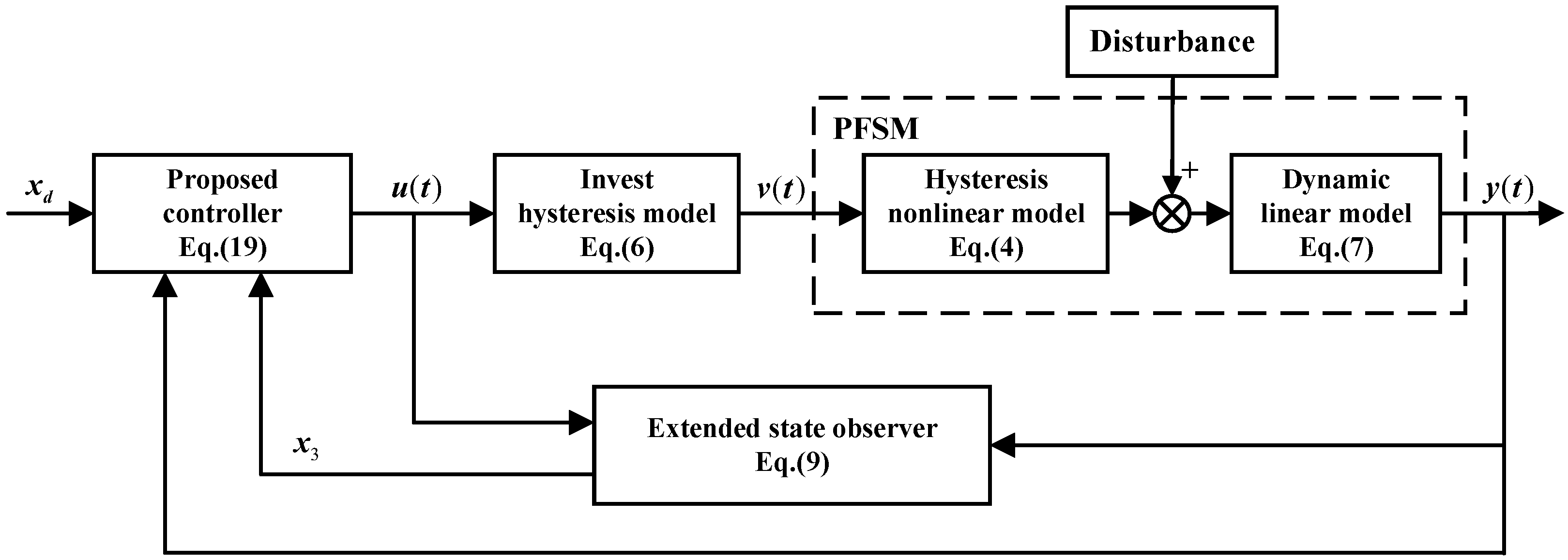
  • Hysteresis compensation: A feedforward compensation strategy based on the P-I inverse hysteresis model is proposed to mitigate nonlinear hysteresis effects, enhancing control accuracy and system performance.
  • Disturbance and uncertainty estimation: The integration of an ESO allows for the real-time estimation of system uncertainties and external disturbances, improving robustness and adaptability under varying operating conditions.
  • Improved control strategy: An improved non-singular fast terminal sliding mode control strategy is proposed, which incorporates a terminal sliding mode surface and an improved adaptive reaching law. This design ensures finite-time convergence while enhancing dynamic performance and significantly improving disturbance rejection capabilities.
The remainder of this paper is structured as follows: Section 2 provides a comprehensive overview of the mechanical and electrical models of the system, establishing the foundation for subsequent analyses. Section 3 details the design methodology and theoretical examination of the suggested control approach. Section 4 presents the parameter identification procedure, describes the experimental setup, and demonstrates the effectiveness of the proposed method through real-time trajectory tracking experiments. Finally, the conclusions of this study are summarized in Section 5.

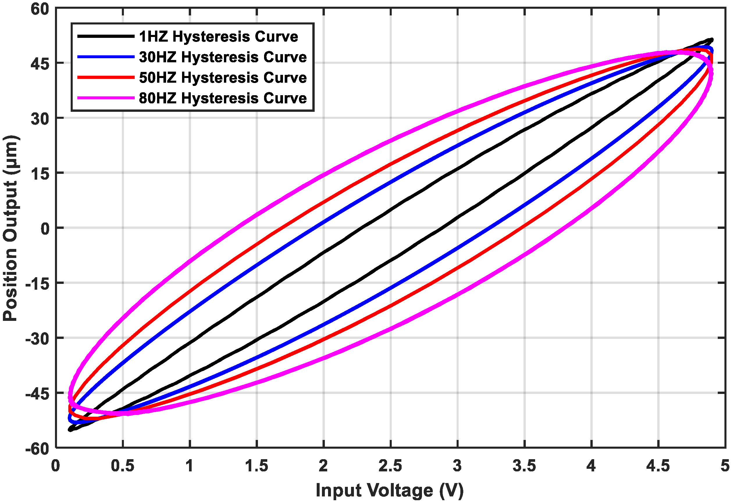
2. System Hysteresis Model

A PFSM is a complex system comprising both linear and hysteresis nonlinear components.
(1) Linear model. A PFSM often uses multiple piezoelectric ceramics to stack to amplify the displacement, thereby driving the deflection of the optical lens. It has general mechanical and electrical characteristics. The linear component can be expressed by the following general second-order dynamic models [32]:
a 0 x ¨ ( t ) + a 1 x ˙ ( t ) + a 2 x ( t ) = b 0 { H [ v ( t ) ] + d 1 ( t ) }
where a 0 , a 1 , a 2 , and b 0 represent the equivalent parameters associated with the mechanical structure of the PFSM system. t is the time variable. x ( t ) and v ( t ) denote the position output and input voltage, respectively. H denotes the modeled hysteresis nonlinear term of the system, which is expressed as a function of the PFSM input voltage v ( t ) . d 1 ( t ) defines the lumped effect of disturbances, taking into account external disturbances and parameter uncertainties.
(2) Hysteresis nonlinear model. The P-I model is used to characterize the hysteresis relationship. The classical P-I model consists of a superposition of multiple play operators, considering that the piezoelectric ceramics receive all the positive voltages, and the one-sided threshold play operator (OSP) is employed to represent the hysteresis behavior. The P-I model based on the OSP operator is expressed as follows [33]:
H ( t ) = w 0 v ( t ) + 0 R w ( r ) F r [ v ] ( t ) d r
where w ( r ) is an integrable function, w 0 is determined by w ( r ) , r is the threshold of the OSP operator and satisfies 0 = r 0 < r 1 < < r n < R , and R is a positive constant. F r [ v ] ( t ) represents the OSP operator for t i 1 < t t i + 1 , which is expressed as follows [33]:
F r [ v ] ( t ) = max v ( t ) r , min [ v ( t ) , F r [ v ] ( t i 1 ) ]
where F r [ v ] ( 0 ) = max v ( 0 ) r , min [ v ( 0 ) , 0 is the initial value of the OSP operator. The transmission properties of the OSP operator and the play operator are shown in Figure 2.
In practice, the P-I model in (2) can be approximated by using a finite operator. Additionally, constant A is introduced to adjust the position of the hysteresis curve. The mathematical expression of the model can be formulated as
H ( t ) = A + i = 1 n w i · max { v ( t ) r i , min [ v ( t ) , F r [ v ] ( t i 1 ) ] }
where r i and w i are the thresholds and weight factors of independent operators; n is the number of operators to be recognized; and the width and size of the hysteresis curve are determined by several parameters, namely, w i , r i , and n.

3. Controller Design and Analysis

Here, the controller is designed to achieve the real-time tracking of the PFSM system. Firstly, a hysteresis inverse model is constructed to counteract the vast majority of hysteresis effects, an ESO is used to estimate unpredictable system states and disturbances in real time, and the control law of the compensated system is designed by introducing the non-singular fast terminal sliding mode method. A block diagram of the proposed controller is illustrated in Figure 3.

3.1. Hysteresis Compensation

A major aim of inverse hysteresis compensation is to eliminate the hysteresis nonlinearity by cascading the inverse hysteresis model with the real hysteresis. In previous studies, the P-I model of (4) has a mathematical inverse model. The weight coefficient and threshold of the inverse model are determined by the parameters of the P-I model, and their evolution relationship is as follows [33]:
w 1 = 1 / w 1 w i = w i / ( j = 1 i w j ) ( j = 1 i 1 w j ) r i = j = 1 i w j ( r i r j )
The inverse model of the P-I model can be expressed as follows:
v ( t ) = i = 1 n w i · max { [ u ( t ) A ] r i , min { [ u ( t ) A ] , F r [ v ] ( t i 1 ) } }
where w i and r i represent the weight coefficient and threshold coefficient of the hysteresis inverse model, respectively, and u ( t ) is the input of the controller.
To verify the effectiveness of the inverse hysteresis compensator, an input voltage u ( t ) = 55 e t sin ( 2 π · 1 t ) is applied to excite the inverse model-based controller. The output of the inverse model is subsequently used as the input to the hysteresis model. The simulation results, including the P-I hysteresis curve, the inverse hysteresis compensator curve, and the input–output curves after compensation, are illustrated in Figure 4. It can be observed that the inverse model is capable of effectively compensating for the hysteresis nonlinearity.

3.2. Extended State Observer

In this section, an ESO is designed to estimate the unmeasurable states of the system and external disturbances. After inverse model compensation, the PFSM system can be simplified as
a 0 x ¨ ( t ) + a 1 x ˙ ( t ) + a 2 x ( t ) = b 0 [ u ( t ) + d ( t ) ]
Let x 1 = x ( t ) , x 2 = x ˙ ( t ) ; combined with (7), the state equation of the system can be deduced as
x ˙ 1 = x 2 x ˙ 2 = b 0 a 0 u a 2 a 0 x 1 a 1 a 0 x 2 + d y = x 1
where x 1 and x 2 represent the state variables of the system, representing the position signal and the speed signal, respectively. y is the position output of the system, d 2 represents the error caused by inverse hysteresis compensation, and d = b 0 a 0 ( d 1 + d 2 ) represents the total system error. The upper bound of the total system error can be expressed by the constant D: d b 0 a 0 d 1 + d 2 D .
According to (8), if the total disturbance term d is considered as the extended variable x 3 , an ESO can be constructed as follows [34]:
d x ^ d t = A x ^ + B u + H ( y y ^ ) y ^ = C x ^
where x ^ is the estimated value of the state variable x i   ( i = 1 , 2 , 3 ) , y ^ is the estimated value of y, and u is the input of the controller. A = 0 1 0 a 2 a 0 a 1 a 0 1 0 0 0 , B = 0 b 0 a 0 0 , C = 1 0 0 , and H is the observer gain matrix. By defining the observer estimation error δ ^ as δ ^ = x x ^ , the observer error state equation can be expressed as
d δ ^ d t = ( A HC ) δ ^
To ensure that the observer error converges to zero over time, the eigenvalues of the coefficient matrix ( A HC ) should all have negative real parts, i.e.,
Re { λ i A HC } < 0 , i = 1 , 2 , 3 .
Remark 1.
The convergence of the observer can be ensured if the matrix ( A HC ) is a negative definite. To guarantee that ( A HC ) is a negative definite, the eigenvalues can be defined as ζ 1 = ζ 2 = ζ 3 = g , ( g > 0 ) . According to [35], H can be designed to be 3 g 3 g 2 g 3 T . The convergence speed of the observer increases with the value of g. However, excessively large values of g can lead to observer divergence.

3.3. Sliding Mode Controller

SMC is a nonlinear control approach recognized for its exceptional robustness, which is especially suitable for systems with parameter uncertainties or external disturbances. To achieve high-accuracy tracking in PFSM systems, the position error function is defined as
δ = x d x 1 δ ˙ = x ˙ d x 2 δ ¨ = x ¨ d x ˙ 2
where x d is the PFSM reference position signal.
In CSMC, the sliding mode surface is designed as
s = λ 1 δ + λ 2 δ ˙
where λ 1 and λ 2 are positive constants.
To ensure the dynamic quality of the reach segment, an exponential reach law can be constructed as follows [36]:
d s d t = ε sign ( s ) k s
where ε > 0 , k > 0 , and sign ( s ) represents the sign function.
Combining (8), (12), (13), and (14), the control law of CSMC is designed as
u = a 0 b 0 λ 2 [ λ 1 ( x ˙ d x 2 ) + λ 2 ( x ¨ d + a 2 a 0 x 1 + a 1 a 0 x 2 d ) + ε sign ( s ) + k s ]
In the system, the state variable x 2 and the external disturbance d cannot be directly measured. Meanwhile, to reduce the impact of measurement noise, x 1 is replaced with x ^ 1 , and the control law in (15) is reformulated through the ESO. The resulting actual control law is expressed as follows
u = a 0 b 0 λ 2 [ λ 1 ( x ˙ d x ^ 2 ) + λ 2 ( x ¨ d + a 2 a 0 x ^ 1 + a 1 a 0 x ^ 2 x ^ 3 ) + ε sign ( s ) + k s ]
In (13), the system state requires an infinite time to converge to the sliding mode surface. To overcome this limitation, a non-singular fast terminal sliding mode surface is designed, drawing inspiration from fast terminal attractors with singularities [21] as follows:
s = β 1 δ + β 2 δ σ 1 / σ 2 + β 3 δ ˙ ϑ 1 / ϑ 2
where β 1 , β 2 , and β 3 are positive parameters; σ 1 , σ 2 , ϑ 1 , and ϑ 2 are positive odd numbers; and 1 < ϑ 1 / ϑ 2 < 2 , σ 1 / σ 2 > 1 . Because there is no negative exponential term, the singularity problem is avoided.
The exponential reach law indicates that increasing the coefficients can enhance the convergence speed. However, increasing the coefficients may induce significant chattering when the system state approaches the sliding mode surface. To achieve a faster convergence rate with less chattering, an improved adaptive sliding mode reaching law is designed to accommodate the dynamic variations in the system state, which is proposed as follows:
d s d t = ε | δ | ( 1 + m | s | 1 + | s | ) s i g n ( s ) k n 0.5 + e s s
where m and n are positive parameters.
The proposed adaptive sliding mode reaching law incorporates a variable-speed arrival term and a variable-exponential arrival term. When s increases, indicating that the system state deviates from the sliding mode surface, the state is rapidly driven back to the surface through the combined effects of the variable-speed term ε | δ | ( 1 + m | s | 1 + | s | )   s i g n ( s ) . and the variable-exponential term k n 0.5 + e s s . Conversely, as s decreases, the variable-exponential term diminishes to zero, while the variable-speed term gradually dominates, approaching ε | δ | s i g n ( s ) . Under the influence of the sliding mode control law, the system state δ progressively approaches zero, leading to a reduction in the switching term gain. Therefore, the improved adaptive sliding mode reaching law not only suppresses chattering but also achieves a faster convergence rate.
Combining (8), (12), (17), and (18), the control law of the proposed controller can be deduced as follows
u = a 0 b 0 [ x ¨ d + a 1 a 0 x ^ 2 + a 2 a 0 x ^ 1 x ^ 3 + ε | δ | ( 1 + m | s | 1 + | s | ) s i g n ( s ) + k n 0.5 + e | s | s + ϑ 2 β 3 ϑ 1 δ ˙ 2 ϑ 1 ϑ 2 ( β 1 + β 2 σ 1 σ 2 δ σ 1 σ 2 1 ) ]
Remark 2.
It is worth noting that the controller proposed in (19) adopts a non-singular fast terminal sliding mode surface to achieve finite-time convergence. The parameter selection effectively avoids the singularity issues commonly encountered in terminal sliding mode control. Moreover, an adaptive function is introduced in the reaching law to dynamically adjust the control gains. Since a power function is incorporated in the switching term, the initial value of the switching gain ε can be set as a relatively large positive constant to accelerate the convergence rate. In addition, the exponential gain can adapt based on the state variable s, while the adaptive function ensures the boundedness of the gain, thereby preventing the instability caused by unbounded gain growth.

3.4. Stability Analysis

The stability of the closed-loop system is analyzed as follows: when the proposed controller is structured as (19), the tracking error δ of the PFSM closed-loop control system (12) will reach stability within a finite time.
According to (10), let A ¯ = ( A HC ) . From Remark 1, it is clear that there exist positive definite matrices Θ and Ψ such that A ¯ T Ψ + Ψ A ¯ = Θ . The Lyapunov function V 0 of the ESO error system is chosen to be expressed as
V 0 = δ ^ T Ψ δ ^
Taking the derivative of V 0 yields
V ˙ 0 = d ( δ ^ ) T d t Ψ δ ^ + δ ^ T Ψ d δ ^ d t = δ ^ T Θ δ ^
If Θ is a positive definite matrix, then it can be deduced that V ˙ 0 0 . On this basis, it can be further confirmed that δ ^ is convergent.
Consider V = V 1 + V 0 as the Lyapunov function of the closed-loop system, where V 1 = 1 2 s 2 . Combining (8), (12), (17), (18), and (19) and taking the derivate of V yield
V ˙ = V ˙ 1 + V ˙ 0 = s ( β 1 δ ˙ + β 2 σ 1 σ 2 δ σ 1 / σ 2 1 δ ˙ + β 3 ϑ 1 ϑ 2 δ ˙ ϑ 1 / ϑ 2 1 δ ¨ ) δ ^ T Θ δ ^ = β 3 ϑ 1 ϑ 2 δ ˙ ϑ 1 / ϑ 2 1 [ ε δ ( 1 + m s 1 + s ) s k n 0.5 + e s s 2 + s ( x ^ 3 x 3 ) + s a 1 a 0 ( x 2 x ^ 2 ) + s a 2 a 0 ( x 1 x ^ 1 ) ] δ ^ T Θ δ ^
The estimation error of the observer | x ^ i x i | is bounded by | x ^ i x i | φ i , ( i = 1 , 2 , 3 ) , where φ i is a positive number. Additionally, ε and k are both positive numbers. According to (22),
V ˙ Φ ( ε δ s + s φ )
where Φ = β 3 ϑ 1 ϑ 2 δ ˙ ϑ 1 / ϑ 2 1 , φ = a 2 a 0 φ 1 + a 1 a 0 φ 2 + φ 3 , and with 1 < ϑ 1 / ϑ 2 < 2 , Φ is a positive number. Take ε δ = ε 0 + φ , where ε 0 > 0 . Equation (23) can be written as
V ˙ Φ ε 0 s = 2 Φ ε 0 ( V 1 ) 1 2
When s 0 , it is guaranteed that V ˙ < 0 . According to Lyapunov’s stability theory, the system will converge to the sliding surface within a finite time, i.e., s = 0 . Once s = 0 , it is guaranteed that the position error function will reach zero in a finite time, i.e., δ ˙ = δ = 0 . The Lyapunov function V 1 complies with V 1 + ξ ( V 1 ) 1 2 0 , where ξ = 2 Φ ε 0 . According to [37], it can be concluded that the time required for V to reach the origin is t c 2 V 1 1 / 2 ( s 0 ) ξ , where s 0 is the initial state of the proposed controller.

4. Experimental Verification

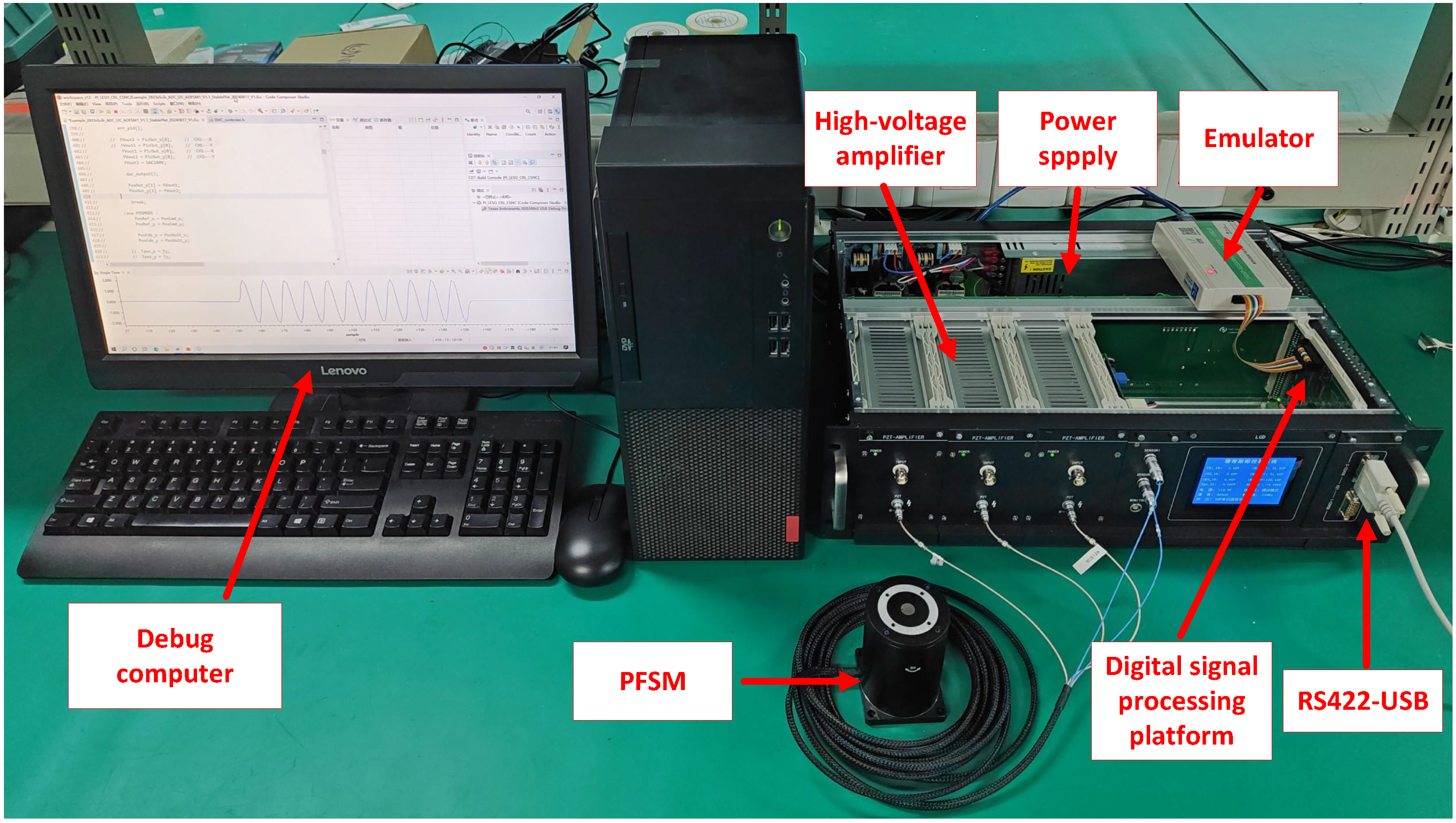
4.1. Experimental Setup

To validate the effectiveness of the proposed control algorithm, a high-precision real-time control platform for a PFSM was developed based on an embedded architecture, as illustrated in Figure 5. The experimental setup mainly consists of a voltage-driven PFSM, a voltage amplifier, an embedded hardware control system, and a host computer for real-time monitoring and debugging. The system’s signal flow is organized as follows: The control algorithm runs in real time on the embedded hardware, generating control signals that are amplified by the voltage amplifier to drive the PFSM for precise angular deflection. The PFSM is equipped with an internal strain gauge sensor that measures the deflection displacement in real time. These sensor signals are fed back to the embedded hardware via its integrated AD module for processing and closed-loop control. During experiments, all relevant data are transmitted to the host computer through an RS422 communication interface for real-time monitoring and performance evaluation, with further analysis carried out using MATLAB (Version number: 2021a).
The control platform is built around Texas Instruments’ DSP28335 (Texas Instruments, Dallas, TX, USA) microprocessor, which integrates 16-bit high-precision AD/DA conversion modules and comprehensive signal acquisition and communication interfaces, enabling efficient real-time control implementation. The core actuator is a P34.T4S-type PFSM (Harbin Core Tomorrow Technology Co., Ltd., Harbin, China), operating within 0–120 V and supporting a maximum deflection angle of 4.6 mrad, meeting high-precision, small-angle steering requirements. To match the PFSM’s voltage range, a voltage amplifier with a gain of 21 amplifies the control signals. The amplified signals are output via the DA module to drive the PFSM directly. The PFSM’s built-in resistive strain gauge sensor monitors real-time deflection, and its signals are sampled by the AD module at 0.0001 s intervals, ensuring precise and fast closed-loop control. The control algorithms are developed in C language using Code Composer Studio (CCS) 12.0.8, with real-time debugging and monitoring via a host computer. Experimental data are transmitted through RS422 and analyzed in MATLAB for a performance evaluation.

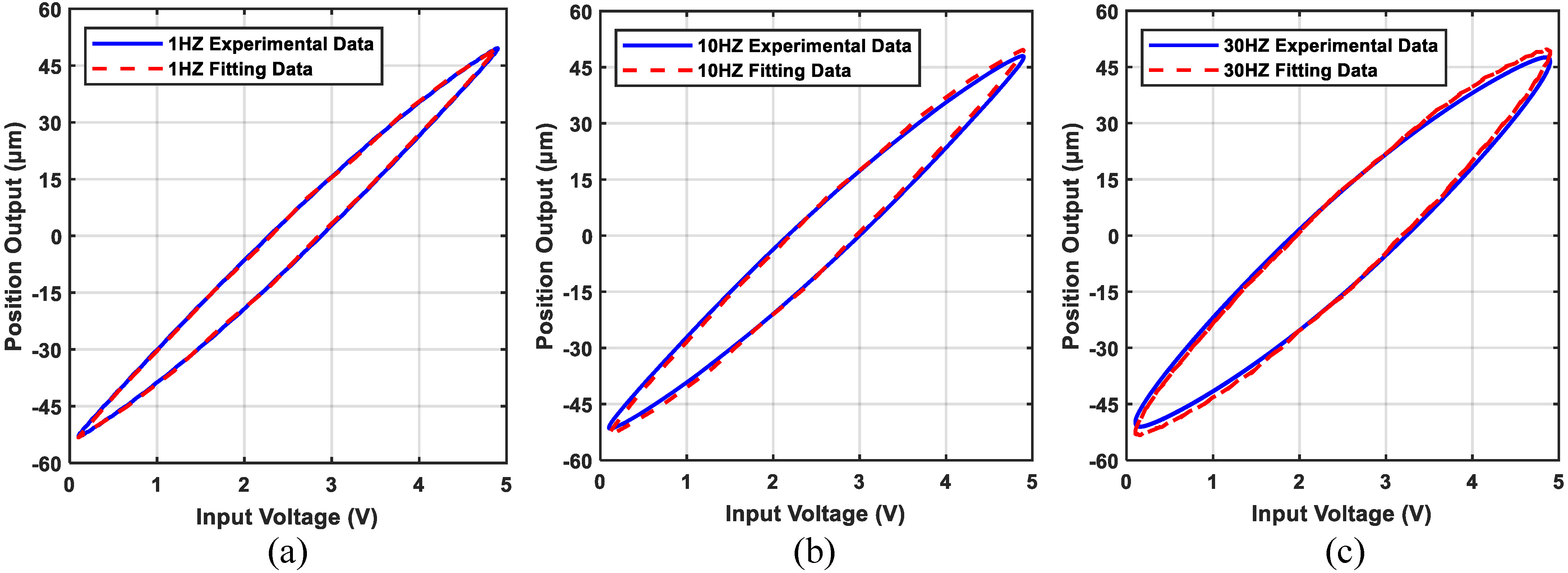
4.2. Model Parameter Identification

The parameter identification of the PFSM system is conducted in two stages. First, the parameters associated with hysteresis nonlinearity are identified using a genetic algorithm (GA)-based approach. The fitness function of the GA is defined by Equation (25). In this study, 10 OSP operators are employed to model the hysteresis behavior. To reduce the complexity of the identification process, uniformly distributed threshold values are adopted, and the weight coefficients are constrained within the interval [ 30 , 30 ] through multiple rounds of optimization. The population size for the genetic algorithm is set to 100. The final identified parameters of the P-I hysteresis model are summarized in Table 1, where A = 56.1 .
F = 1 L i = 1 L ( y i y i ) 2
where y i and y i represent the i-th experimental output and the i-th fitted value, respectively.
Second, the linear dynamics of the system are identified using a frequency sweep method, which is commonly applied in practice. A sinusoidal excitation with a fixed amplitude and a linearly increasing frequency is applied to the system, and both input and output signals are recorded. The collected data are then processed using MATLAB’s System Identification Toolbox for model fitting. The identified parameters of the linear transfer function are as follows: a 0 = 1 , a 1 = 6685 , a 2 = 8.53 × 10 6 , and b 0 = 8.30 × 10 6 . Finally, the parameters of the inverse model-based controller are determined according to Equation (5).
The estimated model output and the actual system output are shown in Figure 6. The results demonstrate that the identified parameters accurately fit the actual hysteresis curve. However, as the input signal frequency increases, the fitting accuracy gradually declines, leading to a reduction in the compensation capability of the inverse model. This introduces greater disturbances into the controller, posing challenges for the control system design.

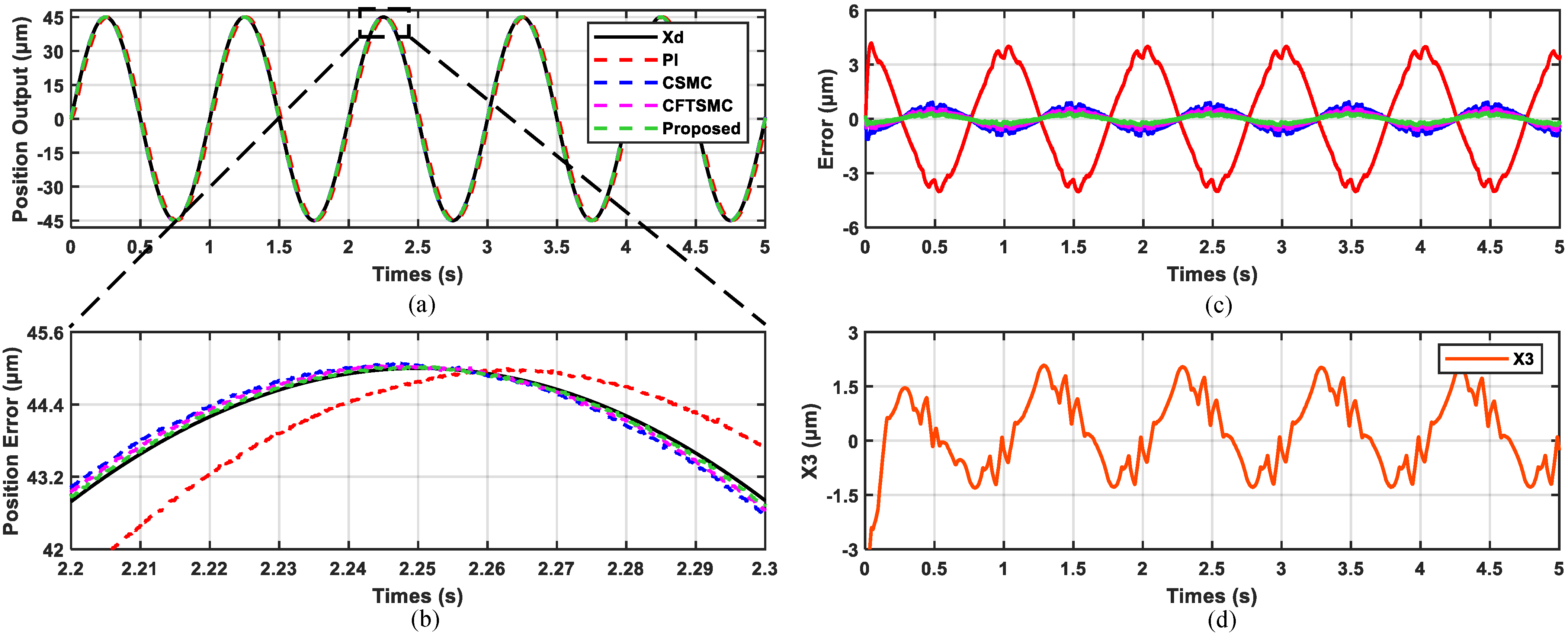
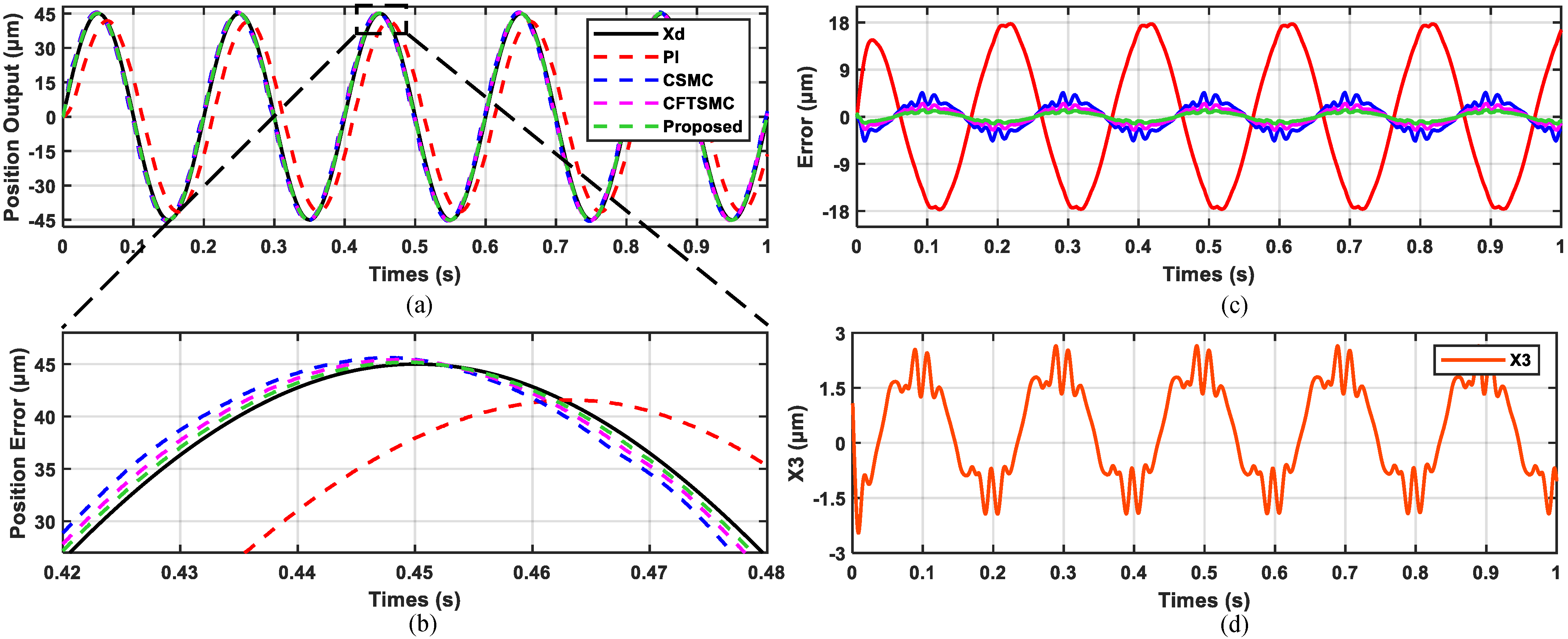
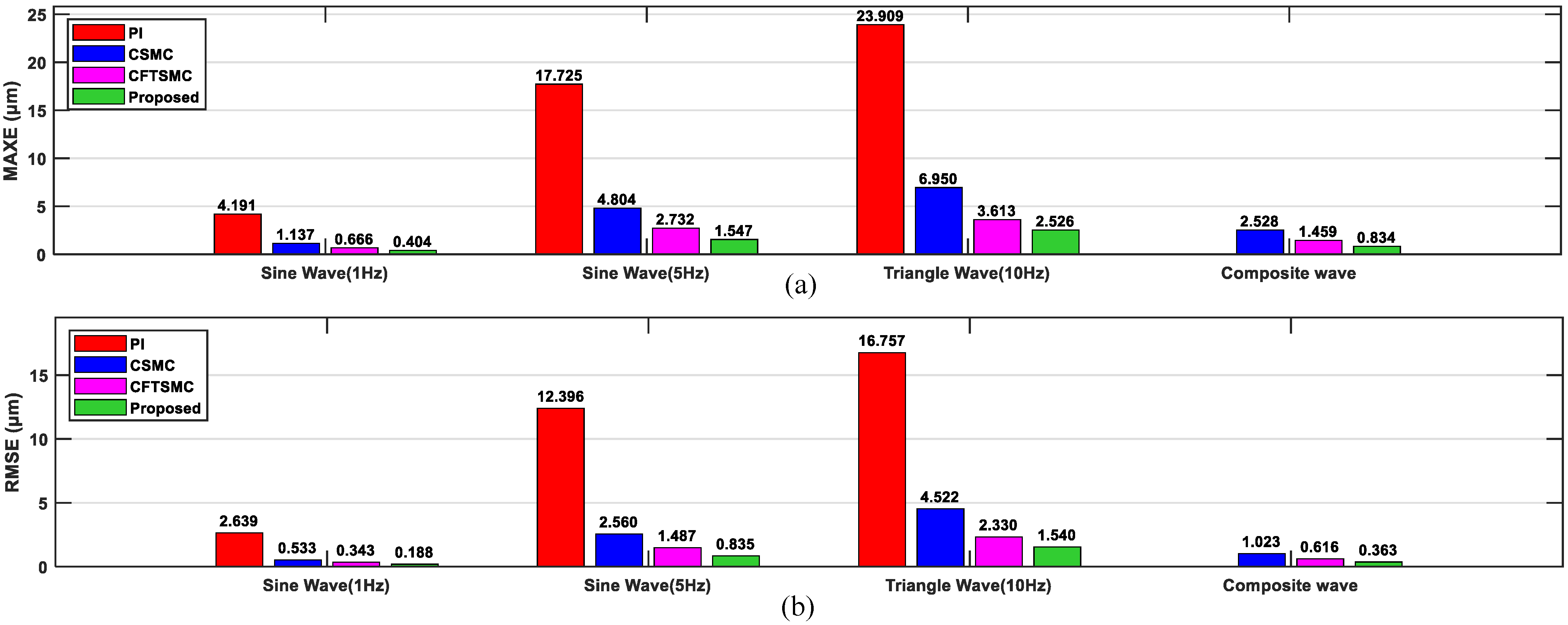
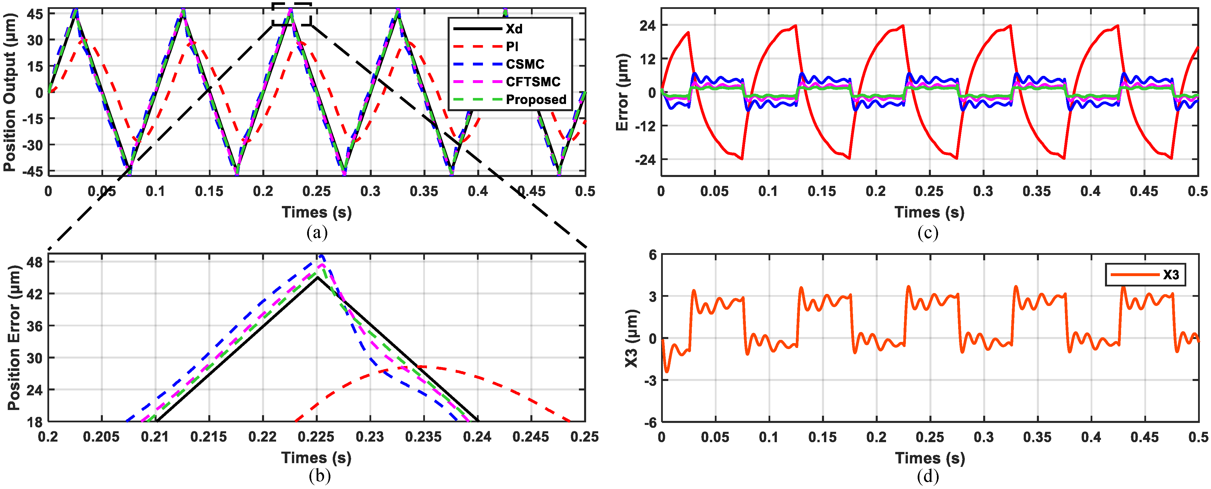
4.3. Real-Time Tracking Experiment

To verify the performance of the recommended controller, a tracking control experiment is conducted using sinusoidal, triangular wave, and composite signals of different frequencies as the desired displacement commands. Proportional integral control (PI), CSMC, conventional fast terminal sliding mode control (CFTSMC) designed by (14), (17), and the proposed controller are employed in the experiment to compare their tracking performance. Meanwhile, step disturbance is applied to test the disturbance rejection capability of the controllers.
To quantify the tracking performance, two evaluation metrics are introduced: the maximum error (MAXE) and the root mean square error (RMSE). The MAXE represents the maximum deviation in model prediction, while the RMSE reflects the overall prediction accuracy of the model. The mathematical formulations of these metrics are as follows:
MAXE = max | x d ( i ) y ( i ) |
RMSE = 1 n i = 1 n | x d ( i ) y ( i ) | 2
To ensure fairness, all three sliding mode control strategies employ an ESO with the same bandwidth. The controller parameters are fine-tuned through multiple experimental iterations, taking into account the practical system constraints. Specifically, parameter ε represents the switching term gain, where an increase leads to greater signal chattering. The parameter k governs the rate at which the system state converges to the sliding surface, while the parameters β 1 , β 2 , and β 3 affect how quickly the error function converges to zero. A comprehensive list of all controller parameters is provided in Table 2.
(1) Test results for sinusoidal signals. To evaluate the performance of the proposed controller, the sinusoidal reference trajectories x d = 45 sin ( 2 π · t )   μ m and x d = 45 sin ( 2 π · 5 t )   μ m , each spanning five cycles, were selected. The experimental results, presented in Figure 7 and Figure 8, demonstrate that all four control schemes (PI, CSMC, CFTSMC, and the proposed controller) achieved satisfactory control performance. Moreover, Figure 7d and Figure 8d illustrate the estimation capability of the ESO, revealing that the estimated disturbance magnitude increased with frequency. This observation suggests a positive correlation between the disturbance magnitude and signal frequency, further indicating that the model’s fitting accuracy deteriorates as the frequency increases. This trend is consistent with the fitting results shown in Figure 6.
In terms of trajectory tracking performance, the PI controller exhibited the worst tracking accuracy, with its tracking error increasing significantly as the signal frequency increased. In contrast, the proposed controller achieved significantly smaller tracking errors than both CSMC and CFTSMC, demonstrating superior capabilities in accurately tracking the sinusoidal reference signals. For a quantitative analysis, the MAXE and RMSE values of the three methods are presented in Figure 9. The proposed controller achieved MAXE values of 0.404 μ m and 1.547 μ m for the two sinusoidal signals, with corresponding RMSE values of 0.188 μ m and 0.835 μ m . Compared to the CSMC method, the proposed controller reduced the RMSE by 64.7% and 67.4%, respectively, and it outperformed the CFTSMC method by reducing the RMSE by 45.2% and 43.8%. The superior tracking performance of the proposed controller is strongly supported by these results.
(2) Test results for triangular wave signals. To validate the proposed controller’s ability to track complex reference trajectories, a triangular wave signal was selected as the test trajectory. This trajectory, defined as x d = 45 tri ( 2 π · 10 t )   μ m , features sharp transitions and non-sinusoidal characteristics, presenting a greater challenge than smooth sinusoidal signals. As shown in Figure 10, the experimental results are consistent with expectations, indicating that the PI controller exhibited the poorest tracking performance, while the proposed controller demonstrated superior tracking capabilities. The proposed controller excelled in handling abrupt trajectory changes. Specifically, compared to the other three methods, it showed several advantages: a higher tracking accuracy, faster response times, and minimal deviation from the reference trajectory. Additionally, it achieved rapid convergence to the predefined trajectory, highlighting its exceptional adaptability to input signal complexity and abrupt variations. As shown in Figure 9, the proposed controller achieved an RMSE of 1.54 μ m when tracking the triangular wave signal. Compared to the CSMC method, the proposed controller reduced the RMSE by 65.9%, and compared to the CFTSMC method, the RMSE was reduced by 33.9%. These findings strongly support the superior robustness and precision of the proposed controller in handling highly dynamic and complex signals.
(3) Test results for composite sinusoidal signals. To rigorously evaluate the robustness of the proposed controller, a composite sinusoidal trajectory was selected as the reference path. The trajectory, defined as x d = 37.5 sin ( 2 π · 1 t ) + 7.25 sin ( 2 π · 10 t )   μ m , introduces dynamic complexity by combining multiple frequency components, simulating conditions where input signals continuously change and remain unpredictable. The previous results demonstrated that the PI controller performed poorly when tracking complex signals. Therefore, the comparative analysis here focused solely on the remaining three methods. As illustrated in Figure 11, all three control schemes achieved stable and accurate tracking of the composite signal. Notably, the proposed method exhibited superior robustness, maintaining a high tracking accuracy and minimal error even under increased signal complexity. In the composite sinusoidal signal tracking experiment, the RMSE achieved by the proposed controller showed a substantial reduction compared to that achieved by CSMC and CFTSMC, decreasing from 1.023 μ m and 0.616 μ m to 0.363 μ m , respectively. These results highlight the proposed controller’s capability to reliably handle multi-frequency trajectories, reinforcing its effectiveness in practical applications involving complex and dynamic inputs.
(4) Results of disturbance test. To comprehensively evaluate the disturbance rejection capabilities of the three control strategies, an experiment was conducted with a reference trajectory x d = 30   μ m . After the system reached a stable state, a disturbance of d = 1.5   μ m was applied at t > 1 s to simulate the potential external interferences encountered during actual operations. The dynamic response trajectories of the three control methods are shown in Figure 12, clearly illustrating their performance differences in response to the disturbance.
An analysis of the response trajectories reveals that the proposed control strategy demonstrates a remarkable advantage in disturbance rejection. Specifically, the proposed controller achieves rapid stabilization after the disturbance is introduced, with a recovery time of only 0.008 s, making it the fastest among the three strategies. Furthermore, the magnitude of the system’s response deviation is significantly smaller, with a drop of merely 0.69 μ m . These results reveal that the proposed control method not only exhibits an exceptional dynamic response speed but also effectively mitigates the impact of disturbances on system performance. This superior performance underscores the potential of the proposed controller for applications requiring high performance and reliability under complex operating conditions.

5. Conclusions

This paper presents an improved sliding mode control strategy, which integrates an ESO and inverse model-based feedforward compensation for high-precision angle tracking in PFSM systems. The ESO is employed to estimate parameter uncertainties and external disturbances, while the inverse model-based feedforward compensation is used to counteract hysteresis effects. Additionally, the introduction of an adaptive reaching law enhances the system’s response speed and robustness. The experimental results, verified through the tracking of sine signals, triangular signals, and composite sine signals at different frequencies, demonstrate the effectiveness of the proposed method. The most notable improvement is in the control accuracy. Disturbance rejection experiments further validate the excellent disturbance rejection capability of the system. The results show that the proposed controller exhibits outstanding robustness and accuracy in compensating for hysteresis nonlinearity, suppressing disturbances, and achieving high-precision trajectory tracking. Furthermore, the proposed strategy is easily deployable on micro-processing platforms, providing valuable insights for engineering applications. Future work will focus on developing more effective online estimation schemes for hysteresis characteristics and applying them to the complete optical targeting system.

Author Contributions

Conceptualization and methodology, E.Z. and S.W.; software, E.Z. and C.Z.; data curation and investigation, E.Z. and W.L.; writing—original draft preparation, E.Z., C.Z. and W.L.; writing—review and editing, S.W. All authors have read and agreed to the published version of the manuscript.

Funding

This research received no external funding.

Data Availability Statement

Data is contained within the article.

Acknowledgments

The authors would like to express their sincere gratitude to the journal editors and reviewers for their meticulous work and valuable advice.

Conflicts of Interest

The authors declare no conflicts of interest.

References

  1. Zhong, J.; Nishida, R.; Shinshi, T. Design and precision tracking control of a high-bandwidth fast steering mirror for laser beam machining. Precis. Eng. 2022, 73, 128–139. [Google Scholar] [CrossRef]
  2. Li, Z.; Li, L.; Zhang, J.; Feng, W. System modeling and sliding mode control of fast steering mirror for space laser communication. Mech. Syst. Signal Process. 2024, 211, 111206. [Google Scholar] [CrossRef]
  3. Wang, G.; Rao, C. Adaptive control of piezoelectric fast steering mirror for high precision tracking application. Smart Mater. Struct. 2015, 24, 035019. [Google Scholar] [CrossRef]
  4. Qi, C.; Lin, J.; Wu, Y.; Gao, F. A Wiener Model Identification for Creep and Vibration Linear and Hysteresis Nonlinear Dynamics of Piezoelectric Actuator. IEEE Sens. J. 2021, 21, 27570–27581. [Google Scholar] [CrossRef]
  5. Yuan, Z.; Zhou, S.; Zhang, Z.; Xiao, Z.; Hong, C.; Chen, X.; Zeng, L.; Li, X. Piezo-actuated smart mechatronic systems: Nonlinear modeling, identification, and control. Mech. Syst. Signal Process. 2024, 221, 111715. [Google Scholar] [CrossRef]
  6. Mohammadzaheri, M.; Al-Sulti, S.; Ghodsi, M.; Soltani, P. Charge Estimation of Piezoelectric Actuators: A Comparative Study. Energies 2023, 16, 3982. [Google Scholar] [CrossRef]
  7. Yang, C.; Youcef-Toumi, K. Principle, implementation, and applications of charge control for piezo-actuated nanopositioners: A comprehensive review. Mech. Syst. Signal Process. 2022, 171, 108885. [Google Scholar] [CrossRef]
  8. Gan, J.; Zhang, X. A review of nonlinear hysteresis modeling and control of piezoelectric actuators. AIP Adv. 2019, 9, 040702. [Google Scholar] [CrossRef]
  9. Hassani, V.; Tjahjowidodo, T.; Do, T.N. A survey on hysteresis modeling, identification and control. Mech. Syst. Signal Process. 2014, 49, 209–233. [Google Scholar] [CrossRef]
  10. Jian, Y.; Huang, D.; Liu, J.; Min, D. High-Precision Tracking of Piezoelectric Actuator Using Iterative Learning Control and Direct Inverse Compensation of Hysteresis. IEEE Trans. Ind. Electron. 2019, 66, 368–377. [Google Scholar] [CrossRef]
  11. Zhang, X.; Tan, Y.; Su, M. Modeling of hysteresis in piezoelectric actuators using neural networks. Mech. Syst. Signal Process. 2009, 23, 2699–2711. [Google Scholar] [CrossRef]
  12. Al Janaideh, M.; Al Saaideh, M.; Rakotondrabe, M. On hysteresis modeling of a piezoelectric precise positioning system under variable temperature. Mech. Syst. Signal Process. 2020, 145, 106880. [Google Scholar] [CrossRef]
  13. Dong, Y.; Hu, H.; Wang, H. Identification and experimental assessment of two-input Preisach model for coupling hysteresis in piezoelectric stack actuators. Sensors Actuators A Phys. 2014, 220, 92–100. [Google Scholar] [CrossRef]
  14. Yang, L.; Zhao, Z.; Li, D. Fractional order neural sliding mode control based on the FO-Hammerstein model of piezoelectric actuator. ISA Trans. 2023, 142, 515–526. [Google Scholar] [CrossRef]
  15. Zeng, X.; Nan, F.; Li, T.; Mo, C.; Su, J.; Wei, K.; Zhang, X. Integrating Strain Gauge Feedback with Adaptive Sliding Mode Motion Control for Piezoelectric Nanopositioning Stage. Actuators 2025, 14, 79. [Google Scholar] [CrossRef]
  16. Wang, G.; Zhou, Y.; Ni, L.; Aphale, S.S. Global fast non-singular terminal sliding-mode control for high-speed nanopositioning. ISA Trans. 2023, 136, 560–570. [Google Scholar] [CrossRef]
  17. Dong, Q.; Liu, Y.; Zhang, Y.; Gao, S.; Chen, T. Improved ADRC with ILC Control of a CCD-Based Tracking Loop for Fast Steering Mirror System. IEEE Photonics J. 2018, 10, 1–14. [Google Scholar] [CrossRef]
  18. Cao, H.; Deng, Y.; Zuo, Y.; Liu, X.; Wang, J.; Lee, C.H.T. A Variable Structure ADRC for Enhanced Disturbance Rejection and Improved Noise Suppression of PMSM Speed System. IEEE Trans. Ind. Electron. 2024, 1–15. [Google Scholar] [CrossRef]
  19. Nguyen, M.L.; Chen, X. MPC Inspired Dynamical Output Feedback and Adaptive Feedforward Control Applied to Piezo-Actuated Positioning Systems. IEEE Trans. Ind. Electron. 2020, 67, 3921–3931. [Google Scholar] [CrossRef]
  20. Cao, H.; Deng, Y.; Liu, J.; Zuo, Y.; Liu, X.; Wang, H.; Lee, C.H.T. Improved Deadbeat Predictive Current Control of PMSM Drives with Repetitive Control-Based Disturbance Correction Observer. IEEE Trans. Power Electron. 2025, 40, 801–812. [Google Scholar] [CrossRef]
  21. Yu, X.; Wu, Y.; Zhihong, M. On global stabilization of nonlinear dynamical systems. In Variable Structure Systems, Sliding Mode and Nonlinear Control; Springer: Berlin/Heidelberg, Germany, 2007; pp. 109–122. [Google Scholar] [CrossRef]
  22. Zhang, S.; Li, Z.; Wang, H.N.; Xiong, T. Fractional order sliding mode control based on single parameter adaptive law for nano-positioning of piezoelectric actuators. Iet Control Theory Appl. 2021, 15, 1422–1437. [Google Scholar] [CrossRef]
  23. Li, S.; Zhou, M.; Yu, X. Design and Implementation of Terminal Sliding Mode Control Method for PMSM Speed Regulation System. IEEE Trans. Ind. Inform. 2013, 9, 1879–1891. [Google Scholar] [CrossRef]
  24. Hou, H.; Yu, X.; Xu, L.; Rsetam, K.; Cao, Z. Finite-Time Continuous Terminal Sliding Mode Control of Servo Motor Systems. IEEE Trans. Ind. Electron. 2020, 67, 5647–5656. [Google Scholar] [CrossRef]
  25. Feng, Y.; Yu, X.; Man, Z. Non-singular terminal sliding mode control of rigid manipulators. Automatica 2002, 38, 2159–2167. [Google Scholar] [CrossRef]
  26. Yang, T.; Deng, Y.; Li, H.; Sun, Z.; Cao, H.; Wei, Z. Fast integral terminal sliding mode control with a novel disturbance observer based on iterative learning for speed control of PMSM. ISA Trans. 2023, 134, 460–471. [Google Scholar] [CrossRef] [PubMed]
  27. Qin, C.; Zhang, Z.; Fang, Q. Adaptive Backstepping Fast Terminal Sliding Mode Control with Estimated Inverse Hysteresis Compensation for Piezoelectric Positioning Stages. IEEE Trans. Circuits Syst. II Express Briefs 2024, 71, 1186–1190. [Google Scholar] [CrossRef]
  28. Song, Z.; Wang, L.; Ling, J.; Wang, L.; Duan, J.; Wang, Y.; Chen, B. Time-delay control scheme with adaptive fixed-time convergent super-twisting fractional-order nonsingular terminal sliding mode for piezoelectric displacement amplifier. ISA Trans. 2024, 146, 99–113. [Google Scholar] [CrossRef]
  29. Sun, X.; Cao, J.; Lei, G.; Guo, Y.; Zhu, J. A Composite Sliding Mode Control for SPMSM Drives Based on a New Hybrid Reaching Law with Disturbance Compensation. IEEE Trans. Transp. Electrif. 2021, 7, 1427–1436. [Google Scholar] [CrossRef]
  30. Wang, Z.; Xu, R.; Wang, L.; Tian, D. Finite-time adaptive sliding mode control for high-precision tracking of piezo-actuated stages. ISA Trans. 2022, 129, 436–445. [Google Scholar] [CrossRef]
  31. Yang, S.; Wang, W.; Wang, R.; Bao, L.; Wang, D.; Lu, K.; Chen, Z.; Wang, C. An improved dynamic Prandtl–Ishlinskii hysteresis model and a PID-type adaptive sliding mode controller for piezoelectric micro-motion platform. Smart Mater. Struct. 2024, 33, 075029. [Google Scholar] [CrossRef]
  32. Xu, Q. Precision Motion Control of Piezoelectric Nanopositioning Stage with Chattering-Free Adaptive Sliding Mode Control. IEEE Trans. Autom. Sci. Eng. 2017, 14, 238–248. [Google Scholar] [CrossRef]
  33. Gu, G.Y.; Zhu, L.M.; Su, C.Y. Modeling and Compensation of Asymmetric Hysteresis Nonlinearity for Piezoceramic Actuators with a Modified Prandtl–Ishlinskii Model. IEEE Trans. Ind. Electron. 2014, 61, 1583–1595. [Google Scholar] [CrossRef]
  34. Cao, H.; Deng, Y.; Zuo, Y.; Li, H.; Wang, J.; Liu, X.; Lee, C.H.T. Improved ADRC with a Cascade Extended State Observer Based on Quasi-Generalized Integrator for PMSM Current Disturbances Attenuation. IEEE Trans. Transp. Electrif. 2024, 10, 2145–2157. [Google Scholar] [CrossRef]
  35. Gao, Z. Scaling and bandwidth-parameterization based controller tuning. Acc 2003, 4, 989-4. [Google Scholar]
  36. Gao, W.; Hung, J. Variable structure control of nonlinear systems: A new approach. IEEE Trans. Ind. Electron. 1993, 40, 45–55. [Google Scholar] [CrossRef]
  37. Moulay, E.; Perruquetti, W. Finite time stability and stabilization of a class of continuous systems. J. Math. Anal. Appl. 2006, 323, 1430–1443. [Google Scholar] [CrossRef]
Figure 1. Hysteresis characteristics of PFSM.
Actuators 14 00170 g001
Figure 2. Input–output relationships of the operator. (a) Play operator. (b) OSP operator.
Actuators 14 00170 g002
Figure 3. Block diagram of the proposed controller.
Actuators 14 00170 g003
Figure 4. Hysteresis and inverse compensation input–output curves. (a) Hysteresis curve. (b) Inverse hysteresis curve. (c) Input–output curve after inverse hysteresis compensation.
Actuators 14 00170 g004
Figure 5. Experimental environment of the piezo-actuated fast steering mirror.
Actuators 14 00170 g005
Figure 6. The output of the predicted and actual models at different frequencies: (a) 1 Hz; (b) 10 Hz; (c) 30 Hz.
Actuators 14 00170 g006
Figure 7. Experimental results of sinusoidal (1 Hz) trajectory tracking. (a) Tracking trajectory. (b) Locally magnified view. (c) Tracking error. (d) Disturbance estimation.
Actuators 14 00170 g007
Figure 8. Experimental results of sinusoidal (5 Hz) trajectory tracking. (a) Tracking trajectory. (b) Locally magnified view. (c) Tracking error. (d) Disturbance estimation.
Actuators 14 00170 g008
Figure 9. MAXE and RMSE of trajectory tracking results of four methods. (a) MAXE. (b) RMSE.
Actuators 14 00170 g009
Figure 10. Experimental results of triangular wave (10 Hz) trajectory tracking. (a) Tracking trajectory. (b) Locally magnified view. (c) Tracking error. (d) Disturbance estimation.
Actuators 14 00170 g010
Figure 11. Experimental results of composite sinusoidal signals trajectory tracking. (a) Tracking trajectory. (b) Locally magnified view. (c) Tracking error. (d) Disturbance estimation.
Actuators 14 00170 g011
Figure 12. Experimental results of sudden step disturbance.
Actuators 14 00170 g012
Table 1. OSP operator thresholds and weighting factors.
i12345678910
r i 0.000.541.081.622.162.703.243.784.324.86
w i 14.932.713.95−2.104.81−1.972.34−0.362.3421.11
Table 2. Parameters of all controllers.
ControllerParameters
PI k p = 0.2 , k i = 180
CSMC λ 1 = 7000 , λ 2 = 1 , k = 500 , ε = 1
CFTSMC β 1 = 7000 , β 2 = 8000 , β 3 = 1 , k = 500 , ε = 1
σ 1 = 3 , σ 2 = 1 , ϑ 1 = 43 , ϑ 2 = 37
Proposed controller β 1 = 7000 , β 2 = 8000 , β 3 = 1 , k = 500 , ε = 1
σ 1 = 3 , σ 2 = 1 , ϑ 1 = 43 , ϑ 2 = 37
m = 1000 , n = 1.2
Disclaimer/Publisher’s Note: The statements, opinions and data contained in all publications are solely those of the individual author(s) and contributor(s) and not of MDPI and/or the editor(s). MDPI and/or the editor(s) disclaim responsibility for any injury to people or property resulting from any ideas, methods, instructions or products referred to in the content.

