Abstract
The requirement for high-speed and high-precision contouring with free-form surfaces in the CNC machining process is increasing. The contour error is an essential criterion for the quality of CNC machining. For the problem of contour error control, the present research is mainly based on position tracking, and the control method directly aiming at contour control has not been well studied. This paper proposed a new type of coordinate transformation-based direct contour control method (CT-DCC) for free-form surface machining trajectories. By real-time monitoring of the contour error and the foot point of the free-form parametric trajectory, the contouring task is decomposed into the contour error control task in the normal direction and the velocity control problem in the feed direction. Using coordinate transformation, the output commands of the two tasks are converted to the axial motion command. CT-DCC completely eliminates position tracking in the traditional control to achieve direct control of the contour error, which provides a new solution for the contour control problem of free-form surface machining. Both the axial velocity control and the axial torque control-based CT-DCC scheme were studied, and the two-axis and three-axis direct contour controllers were tested. The simulation and experiment results show the feasibility of the proposed method.
1. Introduction
The contour error control performance for the high-speed and high-precision machining of complex free-form surface parts has a direct and significant impact. Therefore, many scholars have performed in-depth research on contour error control strategies. The control principle can be roughly divided into the following categories [1]: offline methods, interpolator designs, single-axis tracking controllers, cross-coupled control (CCC) methods, coordinate system design, etc.
Offline control methods include offline feedrate planning methods and offline compensation methods. Liu [2] proposed an improved feedrate planning algorithm based on contour error constraints, which can reduce the response error according to the servo response error model. Longkun [3] proposed a new off-line feedrate interpolation method based on the constraint intersection principle that can satisfy the chord error, velocity, acceleration, and jerk limits of drive axes. In the offline feedrate planning method, the contour error tolerance is treated as planning constraints in the feedrate profile generation [4]. Offline compensation methods are used to add pre-compensations to reduce the contour error and improve the contour error control performance. Yang [5] developed a global toolpath modulation-based contour error pre-compensation method, which incorporates the error compensation issue into the stage of toolpath planning. Qun [6] proposed an adaptive contour error pre-compensation method for five-axis machine tools by constructing a model reference adaptive control. However, the performance of these methods depends on the accuracy of the feed system model. In addition, offline methods cannot tackle the influence of time-varying servo parameters or external disturbances, such as the cutting force, on the contour error.
Compared with offline control methods, interpolator designs can adjust the feedrate online or compensate for control commands to reduce the contour error in real time. Lo and Hsiao designed a CNC machine tool interpolator with a path compensation method for a repeated contour machining process [7]. In addition, some studies have applied the servo dynamic model and contour error constraints to the real-time feedrate planning of interpolators [8,9,10]. However, interpolator designs also require an accurate feed system model and cannot effectively handle perturbations such as cutting forces or parameter drifts during the machining process.
Since the contour error is related to the single-axis tracking error in multi-axis contouring control, many scholars have carried out a lot of research work to improve the accuracy of single-axis servo controllers. Tomizuka [11] proposed the Zero Phase Error-Tracking Controller (ZPETC) for digital control systems to eliminate the poles, zeros, and phase shifts to achieve wide bandwidth and small tracking errors. Many scholars have improved the ZPETC method based on Tomizuka’s work, such as introducing feedforward terms and optimization algorithms [12,13,14]. However, improving single-axis tracking performance cannot guarantee an improvement in contouring accuracy because the mismatch of the dynamic characteristics between the servo drive modules of a multi-axis machine tool and the time lag effect of the control, among other things, can produce contour errors [15].
In 1980, Koren [16] proposed the concept of cross-coupled control (CCC) to solve the contouring control problem of a two-axis motion control system. Srinivasan and Kulkarni [17] designed a proportional control law to achieve the approximate decoupling of contouring error and tracking error. Li et al. [18] designed an intelligent adaptive cross-coupled control strategy based on feature modeling and used proportional feedback cross-coupling control to improve the tracking accuracy of two-dimensional profiles. Wei et al. [19] proposed a Fuzzy PID cross-coupled controller based on an improved PSO algorithm by optimizing controller parameters. Regarding 3D contour error control, Zhang et al. [20] designed and completed a two-layer CCC controller, where the X-Y-axis plane is controlled in the bottom layer and a compensator for the Z-axis is designed in the top layer to reduce the contour error. Liu et al. [21] designed an adaptive cross-coupled pre-compensated controller to compensate for the value of the contour error.
According to the characteristics of CNC machining, many different types of coordinate systems have been proposed to achieve the decoupling of system motion. For a two-axis servo feed system, Lo et al. [22] investigated the Tangential-Contouring Controller (TCC) method, which establishes a tangential-contouring coordinate system, decouples the tracking error into the two coordinate system directions, decomposes the component to the normal direction as the approximate contouring error, and expresses the feed performance in terms of the tangential error. For the three-axis contouring control task, Chiu [23] designed a new Task Coordinate Frame (TCF). Based on the TCF, Chen et al. [24] investigated a free-form curve-oriented contour error estimation algorithm to achieve a first-order approximation of the contour error. Yao [25] and Davis [26] et al. proposed the Orthogonal Global Task Coordinate Frame (GTCF). Lou et al. [27] proposed the Task Polar Coordinate Frame (TPCF) to transform the dynamics in the Cartesian coordinate system under the TPCF coordinate system, which is suitable for contour error control. Shi et al. [28,29] extended the TPCF method to 3D contouring applications. Ke et al. [30] proposed a novel tangential velocity tracking (TVT)-based contouring control framework for biaxial motion systems, which can yield much better contouring performance than the traditional TCF method because of accurate contour error estimations. It is worth noting that this type of method is applicable to limited scenarios, such as straight line and circular arc trajectories, and cannot be generalized to free curves. When the tracking error is large, a lower contour error accuracy may exist.
Most of the commonly used contour error controllers are based on the position tracking control, which inevitably introduces the tracking error. CCC methods can significantly reduce the contour error, but the effect of reducing the tracking error is not obvious [31]. A large tracking error may significantly reduce the contour error control accuracy, especially in complex free-form surface machining with high velocity and large curvature change. In order to solve this problem, many researchers have already proposed a series of methods combining the CCC method and the tracking error compensation strategy [32]. However, the influence of the tracking error still exists in these contour control methods. To overcome this problem, this paper explores a new contour control method that is not based on position tracking but directly uses the contour error as the control objective.
The purpose of this paper is to present a novel direct contour control method based on coordinate transformation (CT-DCC). The remainder of this paper is organized as follows: Section 2 describes the algorithm of direct contour control. Simulation results based on the comparison of the proposed method and contour error CE calculation methods are described in Section 3. In Section 4, the experimental results of real-time control on an X-Y-Z motion table are presented. Finally, Section 5 concludes this paper.
2. Direct Contour Control Method Based on Coordinate Transformation
In this section, the principles and specific algorithms of the CT-DCC method are described.
2.1. Principles of the CT-DCC
The direct contour control (DCC) method proposed in this paper eliminates the position interpolation and the position tracking used in conventional motion control. Since DCC does not require tracking to the target position specified in the position interpolation, it relaxes the time constraints in the contouring and pays more attention to the current contour accuracy. DCC completely eliminates the adverse impact of the tracking error on the accuracy of contour control, as shown in Figure 1.
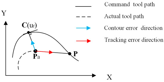
Figure 1.
Contradiction between contour error and tracking error.
The two-dimensional curve is given as an example in Figure 2. is the actual position point, and and are the actual velocities in the X-axis and Y-axis directions, respectively. Based on the algorithm proposed by Liu et al. [33], the foot point parameter , the foot point position and the contour error corresponding to point can be calculated, as shown in Figure 2a. and are the velocity vectors along the contour error direction and the tangential feed direction, which are calculated from and in the world coordinate system by coordinate transformation, as shown in Figure 2b. is the planning tangential feedrate corresponding to , whose direction is orthogonal to the contour error direction, according to the feedrate planning algorithm in the parameter domain [33].
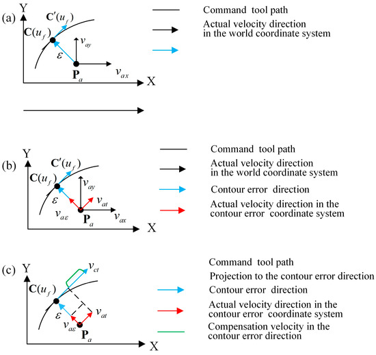
Figure 2.
Direct contour control based on coordinate transformation. (a). Contour error calculation and velocity monitoring. (b). Velocity vector coordinate transformation. (c). Decoupling control.
The idea of CT-DCC is to make the actual machining trajectory as close as possible to the contour of the programmed curve, while also taking the feed direction velocity control into account, to achieve the goal of high-accuracy contour control. CT-DCC is composed of an upper controller and a lower controller. In one control period, the upper controller performs contour error control and feedrate control. In the contour error direction, the actual position point is “pulled” towards the corresponding foot point on the programmed trajectory to complete contour error compensation based on position control, thus generating the compensation velocity in the contour error direction. Meanwhile, in the tangential feed direction, CT-DCC only realizes velocity control to ensure that the actual feed velocity can track the programmed feedrate profile, as shown in Figure 2c.
The two control components in the contour error direction and the tangential feed direction are always orthogonal to each other so that independent decoupling control can be realized to achieve the purpose of accurate contour control.
The lower controller consists of several single-axis controllers, which realize the final motion control of each feed axis of machine tools according to the commands of the upper controller. The upper and lower controllers convert various control variables through coordinate transformation.
2.2. The CT-DCC Algorithm
This section focuses on two CT-DCC algorithms with different type of lower controllers. Both of the CT-DCC methods employ the contour error calculation algorithm described in [33].
2.2.1. CT-DCC Based on Single-Axis Velocity Control
The principle of CT-DCC based on single-axis velocity control is illustrated in Figure 3. Taking X-Y plane contouring control as an example, the lower controllers of the X and Y axes utilize PI-type velocity control. The upper controller includes the P-type contour error controller and the tangential velocity interpolation module to generate the tangential feed velocity command. The detailed algorithm is presented below.
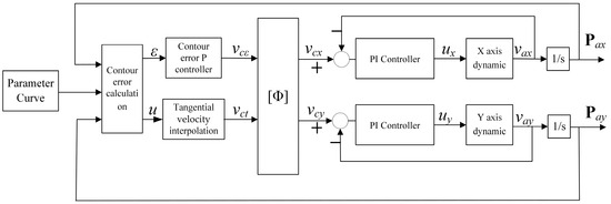
Figure 3.
Schematic diagram of CT-DCC based on single-axis velocity control.
- According to the target programming curve, plan the velocity profile with respect to the curve parameter for DCC and construct the corresponding relationship between the curve parameter u and the tangential velocity v.
- Based on the real-time contour error calculation algorithm [33], calculate the contour error , the foot point parameter , the foot point position corresponding to the actual point of each axis in the world coordinate system, the feed direction unit vector T, and the contour error direction unit vector N corresponding to . Construct the contour control coordinate system.
- Calculate the interpolated velocity command in the tangential feed direction corresponding to the foot point parameter u and the planned velocity profile. is the tangential velocity command.
- According to the contour error , calculate the velocity control command along the contour error direction. is the contour error compensation velocity command.
- Transform the above velocity command vectors from the contour control coordinate system to the world coordinate system. The coordinate transformation is:where:where is coordinate system rotation transformation matrix and . is the velocity command vector in the CT-DCC coordinate system. The velocity command in the world coordinate system can be expressed as:Remark: In this paper, the transformation from the CT-DCC coordinate system to the world coordinate system is defined as a forward transformation, while the transformation from the world coordinate system to the CT-DCC coordinate system is defined as an inverse transformation.
- According to , and the actual velocity ,, the lower controllers of the X and Y axes complete velocity control by the PI controllers and generate the torque command, which is amplified to drive the feeding system on each axis.
- At the end of the servo control period, if the contouring is complete, stop the motion control. Otherwise, return to step 2 and continue the next servo control period calculation.
The CT-DCC algorithm flow based on single-axis velocity control is shown in Figure 4.

Figure 4.
The CT-DCC algorithm flow based on single-axis velocity control.
2.2.2. CT-DCC Based on Single-Axis Torque Control
The principle of CT-DCC based on single-axis torque control is illustrated in Figure 5.

Figure 5.
Schematic diagram of CT-DCC based on single-axis torque control.
The CT-DCC algorithm flow based on single-axis torque control is shown in Figure 6.

Figure 6.
CT-DCC flow based on single-axis torque control.
It can be seen that single-axis torque control-based CT-DCC accomplishes contour control and velocity control in the contour control coordinates, which is more “direct” than the single-axis velocity control-based CT-DCC in the contour control. However, in some servo drives, there is no torque control mode, in which case, only single-axis velocity control-based CT-DCC can be adopted.
The above algorithms are described with two-dimensional CT-DCC. For three-dimensional CT-DCC, the implementation steps are basically the same, except the 3D coordinate system transformation is employed. In addition, this paper adopts the P-PI-type controller, which is the most used method in servo controls, to realize closed-loop control in CT-DCC. Other advanced control methods can also be selected in the application.
2.3. Comparison with Other Contour Control Methods
The differences in various types of contour control methods are briefly mentioned in the Introduction. In this section, the commonly used contour controllers, such as the P-PI control system (Figure 7), the cross-coupled control system (Figure 8), the Fuzzy PID CCC control system (Figure 9), the TCC control system (Figure 10, which is similar to the decoupled control idea in this paper), and the CT-DCC control system (Figure 5), are selected for comparison in the form of block diagrams and a table.

Figure 7.
The P-PI control system.

Figure 8.
The CCC control system.

Figure 9.
The Fuzzy PID CCC control system.

Figure 10.
The TCC control system.
The P-PI control system is the basic form of the position-tracking type contour control system. The interpolated position commands are sent to the axial controllers. The axial controller incorporates a position loop, a speed loop, and a torque loop. Each axial controller realizes position tracking independently, and the actual contour is the result of the actual position in the tracking of each axis. because of the difference in the parameters, dynamic characteristics, and disturbances of each axis, as well as the actual position lag in the position tracking, the contour error is high in the high-speed and large curvature zones.
As a modification of the basic P-PI control system, the CCC control system employs the contour error calculation module, the axial control module, and the cross-coupled control module. The output of the cross-coupled control module is added to the velocity command input of each single-axis controller (some type of CCC module adds the output on the position command). The CCC control system can reduce the contour error compared with the P-PI-type control system. However, the direction of the contour control error is not orthogonal to the direction of the position tracking error; therefore, the contour control performance is affected by the position tracking in the CCC controller.
At present, a lot of contour error control methods are designed based on CCC, such as the sliding mode structure, Fuzzy PID control [19], model reference adaptive control [21], and so forth. The traditional CCC controller is adjusted by PID parameters, and parameter tuning is mainly performed through theoretical calculation and engineering optimization. In the Fuzzy PID CCC Control system, a Fuzzy controller is added to the PID adjustment, which can adaptively adjust the proportional, integral, and differential coefficients.
The TCC control system is another contour control scheme based on single-axis position tracking. Unlike CCC, the contour error is not calculated in the TCC. Instead, the tracking error is decomposed into the normal and tangential directions of the command position point, and then position compensation is performed in these two orthogonal directions. However, because of the existence of the tracking error, the actual contour error foot point position will lag behind the command position. Therefore, in the high-speed and large curvature zone, the direction of the normal compensation vector of the command position may significantly differ from the direction of the actual contour error vector, and the normal component of the tracking error also differs widely from the real contour error, which leads to the degeneration in contouring performance.
The CT-DCC control system is similar to the TCC control system in that both of the controllers utilize decoupled control in the feed and orthogonal directions. But in the CT-DCC control system, the single-axis position tracking is completely eliminated, which essentially avoids the influence of position tracking on contour control. The CT-DCC control system calculates control commands in the two orthogonal directions based on the contour state feedback at the current time, including the contour error and the feed direction of the foot point, and no longer requires information such as the command position, the tracking error, etc. In addition, the CT-DCC control system utilizes the real contour error value and the real curve parameter at the foot point rather than the estimated ones, which further improves contour control performance. A comparison of these contour controllers is shown in Table 1 (N/A is short for Not applicable).

Table 1.
Comparison of different contour control methods.
3. Simulation Study
In this section, simulation experiments and data analysis of the CT-DCC control method will be carried out using two-dimensional and three-dimensional NURBS curves as examples, respectively.
3.1. Two-Dimensional Simulation Experiments
3.1.1. 2D CT-DCC System Model
The bi-axial motion control system model of 2D CT-DCC based on single-axis velocity control is illustrated in Figure 11a. The simulation model includes the following six modules: the parameter curve state calculation module, the tangential velocity interpolation module, the contour error calculation module, the contour error control module, the forward feed velocity transformation module, the X/Y-axis velocity PI control module, and the X/Y-axis feed system module.
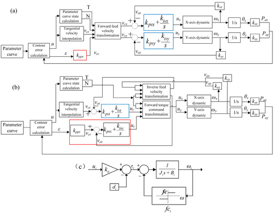
Figure 11.
Two different DCC simulation models. (a) The CT-DCC simulation model based on single-axis velocity control. (b) The CT-DCC simulation model based on single-axis torque control. (c) The X/Y-axis feed system.
The simulation model of the 2D CT-DCC system based on single-axis torque control is shown in Figure 11b. It can be observed that the velocity control loops are moved to the upper controller by employing the PI-type velocity control both in the tangential and contour error directions. In addition, the inverse feed velocity transformation module and the forward torque command transformation module are introduced. The parameters in the two models include the following: u is the foot point parameter of the curve corresponding to the current actual position, is the contour error, is the proportional gain in the contour control position loop, is the contour error compensation velocity command, is the tangential velocity command output by the tangential velocity interpolation module, T and N are the tangential direction unit vector and the contour error direction unit vector, respectively, and are the X/Y-axis velocity commands in the world coordinate system, and are the actual velocities of the X/Y axes, and are the proportional gains in the X/Y-axis velocity controllers, and are the integral gains in the X/Y-axis velocity controllers, and and are the torque commands output to the X/Y-axis feed system.
The X/Y-axis feed system dynamic model is shown in Figure 11c. The model simulates a ball–screw motion system driven by a permanent magnet synchronous motor (PMSM). In the axis dynamic, is the torque gain of the motor driver, is the torque offset caused by the drift of the amplifier, is the moment of inertia of the load, is the Coulomb friction, and is the viscous damping coefficient. , , and are the velocity, angular displacement, and linear motion position of the axis.
3.1.2. 2D Simulation Results
In order to compare the proposed CT-DCC method with other contour control methods, simulation experiments were carried out with the well-known “butterfly”-shaped NURBS curve, as shown in Figure 12. The parameters for the simulation model are listed in Table 2. The parameter-tuning method of the P controller and PI controller was obtained from the literature [34]. The parameters of the feed axis dynamics were based on the system identification experiment with the X–Y motion table. The control period in the simulations was 1 ms.
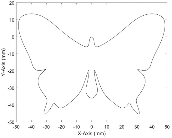
Figure 12.
Butterfly curve.

Table 2.
Simulation experiment parameters of 2D CT-DCC.
The constraints of the velocity planning in the simulation experiments can be found in the literature [33]. The plot of parameter u versus the feed velocity command is shown in Figure 13.
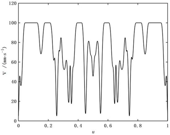
Figure 13.
Two-dimensional velocity planning.
The comparison models selected for the simulation experiments included the following: the P-PI control model, the TCC control model, the CCC model, CT-DCC based on single-axis velocity control, and CT-DCC based on single-axis torque control. The parameters of the P-PI control model, CCC model, and Fuzzy PID CCC model are shown in Table 3. is set to 75 in the CCC model.

Table 3.
Parameters of the P-PI control, the CCC, and Fuzzy PID CCC simulation models.
The TCC model adopted the method introduced in the literature [7]. The model control parameters included the following: the tracking error normal component P controller (), the tracking error tangential component P controller (), the X-axis velocity PI controller (), and the Y-axis velocity PI controller (), as shown in Table 4.

Table 4.
Parameters of the TCC simulation model.
The contour error calculation algorithm used in the CCC, Fuzzy PID CCC, and CT-DCC methods was from the literature [33], which can obtain the exact contour error value instead of an approximate one. There was no contour error calculation module in the PID or TCC controllers.
To compare the contour error control performance under different methods, three evaluation indexes were used, i.e., the maximum value (max), the mean value (mean), and the root mean square value (RMS) of the contouring error, as shown in Table 5. The simulation results showed that the values of the contour error indexes were the largest in P-PI control. After applying TCC or CCC, there was a great improvement in the contour error compared with P-PI control, and the performance of CCC was better than that of TCC since the exact contour error calculation for NURBS was used in the simulation. In addition, the performance of the Fuzzy PID CCC was better than that of CCC because of the introduction of Fuzzy rules in the single-axis PID controller. Moreover, the CT-DCC method with two different single-axis control strategies proposed in this paper had better results than other methods. This implies that CT-DCC improved contour accuracy by eliminating the influence of single-axis position tracking control.

Table 5.
Data analysis of the 2D simulation experiment (mm).
For CT-DCC(velocity) and CT-DCC(torque), the experimental results show that the CT-DCC(torque) method had better performance. Since CT-DCC based on single-axis torque control moves the velocity loop to the upper contour controller, it is more effective for contour error control. Therefore, if the motor driver supports both velocity and torque control, the CT-DCC method based on single-axis torque control is preferred. In view of this, in the later sections of this paper, the CT-DCC method based on single-axis torque control is chosen for study.
3.2. There-Dimensional Simulation Experiments
3.2.1. 3D CT-DCC System Model
The simulation model of the 3D CT-DCC system based on single-axis torque control is shown in Figure 14. It is similar to the 2D CT-DCC model, except that the inverse velocity transformation and the forward torque command transformation module handle 3D vectors.

Figure 14.
Three-dimensional CT-DCC simulation model.
3.2.2. There-Dimensional Simulation Results
The 3D CT-DCC test simulated the machining of a free-form NURBS surface, as shown in Figure 15. By employing the isoparametric method, the tool path was generated for the machining, as shown in Figure 16, the yellow line is the tool path.
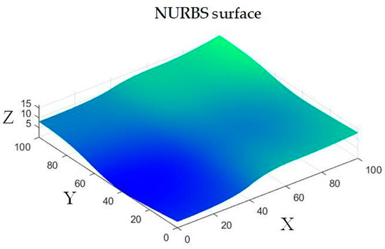
Figure 15.
NURBS surface.
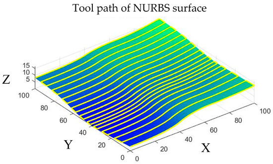
Figure 16.
Tool path of the NURBS surface.
The feedrate planning result is shown in Figure 17. The curve parameter ranges from 0 to 39, which means that there were 39 separate NURBS segments on the entire machining trajectory, and for each NURBS segment, the parameter range was 0 to 1. The simulation parameters are shown in Table 6.
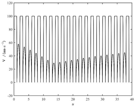
Figure 17.
Feed velocity planning result for the 3D CT-DCC simulation.

Table 6.
Parameters of the 3D CT-DCC simulation model.
The simulation experiments verified the feasibility of the 3D CT-DCC scheme, and the experimental results are shown in Table 7.

Table 7.
Data analysis of the 3D simulation experiment (mm).
4. Experimental Investigation
4.1. Experimental Setup
The three-axis motion platform (Figure 18) was used to verify the effectiveness of the proposed algorithm. The platform includes a real-time PC controller, an interface board, PMSM servos, and a three-axis moving platform. The model of the three PMSM servo motors was Mitsubishi HC-UFS13 [35], and the model of the servo drivers was Mitsubishi MR-J2S-10A [36]. The drivers were set to the torque control mode, and the closed-loop motion control was implemented in the PC controller. The moving table was driven by the lead screws connected to the PMSM motors.
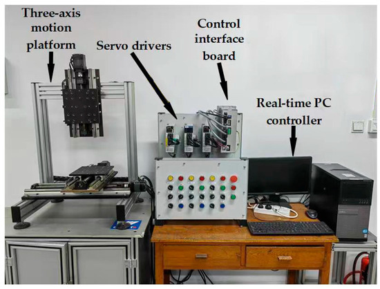
Figure 18.
Experimental verification platform.
The control algorithm was developed in the Matlab/Simulink R2020b environment on a Windows PC with the “Simulink Desktop Real-Time” library to enable real-time control ability [37]. The control interface board was designed for signal conversion and data exchange between the PC controller and the drivers. The interface board and the PC employed the UDP protocol to achieve real-time communication over the Ethernet. On the interface board, the required motor torque command was converted to the voltage output signal for the driver, and the feedback encoder pulses of the motor were counted for the position and velocity measurement. Table 8 lists the parameters of the axial driving system.

Table 8.
Parameters of the axial driving system.
4.2. Experimental Results and Discussion
4.2.1. Two-Dimensional Experimental Validation
The “butterfly” tool path was used in the experiments. The control period in the experiments was 1 ms. The P-PI control system, the CCC system, the TCC control system, the Fuzzy PID CCC system, and the CT-DCC system based on single-axis torque control were employed for comparison. The control parameters were the same as in the simulation. The experimental results are shown in Table 9.

Table 9.
Contouring experimental results (mm).
Based on the experimental results, it can be concluded that the contour error performance in P-PI and TCC was limited because of the lack of contour error calculation and control. In contrast, the maximum, mean, and RMS values of the contour error obtained with the CT-DCC control system were minimal. The mean contour error was reduced by 26.9% compared with the CCC controller. In addition, the Fuzzy PID CCC control system improved the performance of the CCC control system, especially in mean and RMS values of the contour error, but the effect was still not as effective as the CT-DCC control system.
Compared with the simulation result, it can be seen that the experimental contour error indexes of P-PI, CCC, Fuzzy PID CCC, and CT-DCC were slightly higher than those in the simulation, while the experimental result of TCC was slightly better than the simulation result. The reason may be the differences between the feed axis model in the simulation and the real feed system. However, the differences were limited, and the contour error of TCC was still much higher than that of CCC, Fuzzy PID CCC, and CT-DCC, which employ the exact contour error calculation.
The actual motion trajectory is shown in Figure 19. The reference curve is the programmed curve, while P-PI/TCC/CCC/Fuzzy PID CCC/CT-DCC are the actual trajectories obtained by the P-PI, TCC, CCC, Fuzzy PID CCC, and CT-DCC methods, respectively. Two representative regions are selected to zoom in on the NURBS trajectory as follows: region A with smooth curvature change and region B with large curvature change. It can be seen that CT-DCC had excellent performance under different curvature conditions, especially in the large curvature zone. Compared with the other three contour controllers, the actual trajectory of CT-DCC was the closest to the programmed curve.
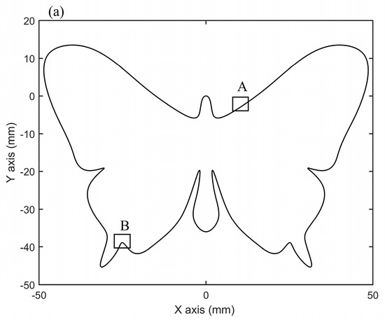
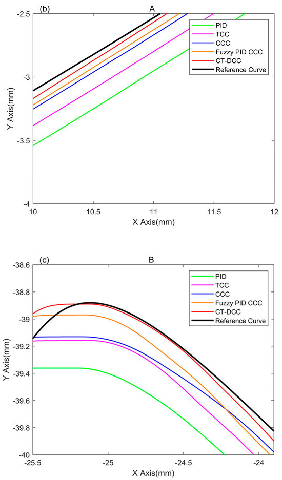
Figure 19.
Actual trajectory comparison of the butterfly curve. (a) Selected area on the curve, (b) enlarged area A, and (c) enlarged area B.
4.2.2. Three-Dimensional Experimental Validation
Three-dimensional CT-DCC was also validated in the experimental platform. The controller parameters, velocity planning constraints, and 3D programming surfaces were the same as in the 3D CT-DCC simulation. The experiments showed that the 3D contouring task can be smoothly performed by the proposed method, so the effectiveness of 3D CT-DCC with free-form trajectory composed of multiple NURBS results was validated. The contouring error was recorded and the result is shown in Table 10.

Table 10.
The 3D CT-DCC experimental results (mm).
4.2.3. Real-Time Performance Evaluation
Real-time performance has a significant impact on the implementation of the controller, the reliability of CNC machine tool operation, etc. To evaluate the real-time computing load of the control algorithm, the execution times of the contouring control program in each control cycle were recorded. The processor of the controller used in this study was the Intel Core i5-2400 running at 3.10 Ghz. The 2D CCC, 2D CT-DCC, and 3D CT-DCC methods were tested to evaluate real-time performance. The 2D CCC method was chosen as a benchmark for comparison. All of the test algorithms used the same contour error calculation method. The execution time was recorded by the high-precision timer in the controller. The maximum and the average execution time are shown in Table 11.

Table 11.
Real-time performance of the contouring algorithms (ms).
The results in Table 11 show that the execution time of the 2D CCC algorithm was the shortest, the mean execution time of the 2D CT-DCC algorithm had a slight increase of 6.1% compared with the 2D CCC algorithm. Because the 3D CT-DCC algorithm was more complex (because of 3D coordinate transformation and three-axis control), it had a larger computing load, which increased by 51.4% in terms of the mean execution time compared with the 2D CT-DCC algorithm. However, in terms of the maximum execution time, all three algorithms can satisfy the real-time requirement of the 1ms servo control period.
5. Conclusions
To solve the problem of contour accuracy degradation in high-speed freeform trajectory motion with conventional position tracking-based controllers, a novel direct contouring control scheme based on coordinate transformation is presented in this paper. The new control scheme completely removed the single-axis position tracking loop, which may lead to a contradiction with the contour error control. Based on the idea of coordinate transformation, CT-DCC utilizes a direct contour control system to realize the decoupling control of the contour error and the feed velocity. By eliminating single-axis position tracking, CT-DCC avoids the influence of the tracking error control on the contour error control. For the realization of CT-DCC, the exact contour error and the foot point calculation method are introduced to construct the two-axis and three-axis controllers. The simulation and experimental results showed that CT-DCC effectively improves the contour error control performance. Compared with the traditional cross-coupled controller, it reduces the maximum contour error by 40%, and the algorithm can satisfy the real-time control requirements of the CNC system.
Author Contributions
Conceptualization, Z.L.; methodology, Z.L. and T.C.; software, Z.L.; validation, Z.L. and W.W.; resources, J.Z., C.Q. and P.Z.; data curation, Z.L.; writing—original draft preparation, Z.L. and W.W.; writing—review and editing, Z.L. and J.D. All authors have read and agreed to the published version of the manuscript.
Funding
This research was funded by China Railway Design Corporation grant number 2023A0253802. And The APC was funded by China Railway Design Corporation.
Data Availability Statement
The data underlying this article are available in the article.
Conflicts of Interest
Author Zhe Liu/Tao Cui/Jiqing Zhang/Chunyu Qi/Peng Zhang were employed by the company China Railway Design Corporation. The remaining authors declare that the research was conducted in the absence of any commercial or financial relationships that could be construed as a potential conflict of interest.
Abbreviations
| Notation | Meaning |
| contour error | |
| foot point parameter | |
| contour error compensation velocity command | |
| tangential velocity command | |
| X/Y-axis velocity command | |
| X/Y-axis actual velocity | |
| X/Y-axis torque command | |
| contour error compensation actual velocity | |
| tangential actual velocity | |
| X/Y-axis actual position | |
| X/Y-axis position command | |
| tracking error in the X/Y-axis direction | |
| normal component of tracking error | |
| tangential component of tracking error | |
| T | tangential direction unit vector |
| N | contour error direction unit vector |
| X/Y-axis angular velocity | |
| X/Y-axis angular displacement | |
| torque gain of the motor driver | |
| torque offset caused by the drift of the amplifier | |
| moment of inertia of the load | |
| Coulomb friction | |
| viscous damping coefficient | |
| normal component of torque command | |
| tangential component of torque command | |
| contour control position loop proportional gain | |
| contour control velocity loop proportional gain | |
| contour control velocity loop integral gain | |
| tangential velocity control proportional gain | |
| tangential velocity control integral gain | |
| proportional gains of the X/Y-axis velocity controllers | |
| integral gains of the X/Y-axis velocity controllers |
References
- Jia, Z.; Ma, J.; Song, D. A review of contouring-error reduction method in multi-axis CNC machining. Int. J. Mach. Tools Manuf. 2018, 125, 34–54. [Google Scholar] [CrossRef]
- Liu, B.; Zhang, H.; Liu, Y. A Feedrate Planning Method in CNC System Based on Servo Response Error Model. Electronics 2023, 12, 3150. [Google Scholar] [CrossRef]
- Xu, L.; Zhang, W.; Geng, Z.; Xu, J. Crossing principle-based feedrate planning method for 5-axis CNC milling with drive constraints. J. Ind. Prod. Eng. 2020, 37, 321–332. [Google Scholar] [CrossRef]
- Oh, J.Y.; Sim, B.; Lee, W.J.; Choi, S.J.; Lee, W. Model-based feed rate optimization for cycle time reduction in milling. J. Manuf. Process. 2023, 94, 94289–94296. [Google Scholar] [CrossRef]
- Yang, L.; Mansen, C.; Yuwen, S. Global toolpath modulation–based contour error pre-compensation for multi-axis CNC machining. Int. J. Adv. Manuf. Technol. 2023, 125, 3171–3189. [Google Scholar] [CrossRef]
- Xiao, Q.-B.; Wan, M.; Wan, Y.; Wan, W.-H. Pre-compensation of contour errors for five-axis machine tools through constructing a model reference adaptive control. Mech. Mach. Theory 2023, 183, 105258. [Google Scholar] [CrossRef]
- Lo, C.; Hsiao, C. CNC machine tool interpolator with path compensation for repeated contour machining. Comput. Aided Des. 1998, 30, 55–62. [Google Scholar] [CrossRef]
- Wu, B.; Ma, J.; Wei, L. NURBS Interpolator with Scheduling Scheme Combining Cubic and Quartic S-shaped Feedrate Profiles Under Drive and Chord Error Constraints. Comput.-Aided Des. 2022, 152, 103380. [Google Scholar] [CrossRef]
- Jiang, J.; Lin, F.; Zhang, Y. A Real-Time Feedrate Planning Method and Efficient Interpolator With Minimal Feedrate Fluctuation for Parametric Toolpath. IEEE Access 2019, 7, 112953–112962. [Google Scholar] [CrossRef]
- Wang, T.; Cao, L.; Zhang, Y.; Dong, Z.; Jia, S.; Tian, C.; Liu, Q. NURBS interpolator with pre-compensation based on discrete inverse transfer function for CNC high-precision machining. Int. J. Adv. Manuf. Technol. 2022, 121, 1315–1335. [Google Scholar] [CrossRef]
- Tomizuka, M. Zero Phase Error Tracking Algorithm for Digital Control. J. Dyn. Syst. Meas. Control 1987, 109, 65–68. [Google Scholar] [CrossRef]
- Zhong, G.; Shao, Z.; Deng, H.; Ren, Z. Precise Position Synchronous Control for Multi-Axis Servo Systems. IEEE Trans. Ind. Electron. 2017, 64, 3707–3717. [Google Scholar] [CrossRef]
- Li, J.; Zhang, A.; Wang, Q.; Lin, Z. Design and Control of High Precision two Axis Servo Scanning System in Space. J. Phys. Conf. Ser. 2021, 1820, 012044. [Google Scholar] [CrossRef]
- Qian, Z.; Xu, W.; Qunjing, W. Improved Active Disturbance Rejection Control of Dual-Axis Servo Tracking Turntable with Friction Observer. Electronics 2021, 10, 2012. [Google Scholar] [CrossRef]
- Jiang, J.; Li, B.; Dong, Q.; Zhang, H.; Ye, P.; Jiang, S. Contour error dynamic analysis and predictive control for multi-axis motion system. Int. J. Adv. Manuf. Technol. 2023, 126, 5501–5514. [Google Scholar] [CrossRef]
- Koren, Y. Cross-Coupled Biaxial Computer Control for Manufacturing Systems. J. Dyn. Syst. Meas. Control-Trans 1980, 102, 265–272. [Google Scholar] [CrossRef]
- Srinivasan, K.; Kulkarni, P.K. Cross-Coupled Control of Biaxial Feed Drive Servomechanisms. J. Dyn. Syst. Meas. Control 1990, 112, 225–232. [Google Scholar] [CrossRef]
- Li, Z.; Wang, T.K.; Wang, S.J. Cross-coupling control strategy based on intelligent adaptive control for cross-shaped dual-axis linear motors. IET Electr. Power Appl. 2023, 17, 1212–1224. [Google Scholar] [CrossRef]
- Wei, J.; Xiang, C.; Bo, X. Cross-coupled control for contour tracking error of free-form curve based on fuzzy PID optimized by improved PSO algorithm. Meas. Control 2022, 55, 807–820. [Google Scholar] [CrossRef]
- Zhang, D.; Yang, J.; Chen, Y. A two-layered cross coupling control scheme for a three-dimensional motion control system. Int. J. Mach. Tools Manuf. 2015, 98, 12–20. [Google Scholar] [CrossRef]
- Liu, W.; Ren, F.; Sun, Y. Contour error pre-compensation for three-axis machine tools by using cross-coupled dynamic friction control. Int. J. Adv. Manuf. Technol. 2018, 98, 551–563. [Google Scholar] [CrossRef]
- Lo, C.; Chung, C. Tangential-Contouring Controller for Biaxial Motion Control. Trans. ASME 1999, 121, 126–129. [Google Scholar] [CrossRef]
- Chiu, G.T.C.; Omizuka, M. Contouring control of machine tool feed drive systems: A task coordinate frame approach. IEEE Trans. Control Syst. Technol. 2001, 9, 130–139. [Google Scholar] [CrossRef]
- Chen, S.; Liu, H.; Ting, S.C. Contouring control of biaxial systems based on polar coordinates. IEEE/ASME Trans. Mechatron. 2002, 7, 329–345. [Google Scholar] [CrossRef]
- Yao, B.; Hu, C.; Wang, Q. An Orthogonal Global Task Coordinate Frame for Contouring Control of Biaxial Systems. IEEE/ASME Trans. Mechatron. 2012, 17, 622–634. [Google Scholar] [CrossRef]
- Davis, T.A.; Shin, Y.C.; Yao, B. Adaptive Robust Control of Circular Machining Contour Error Using Global Task Coordinate Frame. J. Manuf. Sci. Eng. 2015, 137, 014501. [Google Scholar] [CrossRef]
- Lou, Y.; Meng, H.; Yang, J. Task Polar Coordinate Frame-Based Contouring Control of Biaxial Systems. IEEE Trans. Ind. Electron. 2014, 61, 3490–3501. [Google Scholar] [CrossRef]
- Shi, R.; Lou, Y. Three-Dimensional Contouring Control: A Task Polar Coordinate Frame Approach. IEEE Access 2019, 7, 63626–63637. [Google Scholar] [CrossRef]
- Shi, R.; Lou, Y.; Zhang, X. A Novel Task Coordinate Frame Reduced- Dimension 3-D Contouring Control. IEEE Trans. Autom. Sci. Eng. 2018, 15, 1852–1863. [Google Scholar] [CrossRef]
- Runji, K.; Taiyong, W.; Jingchuan, D. Tangential velocity tracking-based task coordinate frame approach for contouring control of biaxial motion systems. Int. J. Adv. Manuf. Technol. 2023, 124, 3489–3504. [Google Scholar] [CrossRef]
- Lu, Y.; Zhao, J.; Zhang, Z. Research on a novel integrated control strategy for contour error compensation of biaxial CNC machining. Int. J. Adv. Manuf. Technol. 2024, 130, 385–402. [Google Scholar] [CrossRef]
- Zhang, T.; Wu, C.; Zou, Y. Chord error constraint based integrated control strategy for contour error compensation. Front. Mech. Eng. 2020, 15, 645–658. [Google Scholar] [CrossRef]
- Liu, Z.; Dong, J.; Wang, T. Real-time exact contour error calculation of NURBS tool path for contour control. Int. J. Adv. Manuf. Technol. 2020, 108, 2803–2821. [Google Scholar] [CrossRef]
- Li, S.; Jiang, Q. Study on pid parameters tuning method based on Matlab/Simulink. In Proceedings of the 2011 IEEE 3rd International Conference on Communication Software and Networks, Xi’an, China, 27–29 May 2011; pp. 408–411. [Google Scholar] [CrossRef]
- The Mitsubishi, Inc. “HC-UFS13” mitsubishielectric.com. Available online: https://dl.mitsubishielectric.com/dl/fa/document/manual/servo/sh3181/sh3181l.pdf (accessed on 23 August 2024).
- The Mitsubishi, Inc. “MR-J2S-10A” mitsubishielectric.com. Available online: https://dl.mitsubishielectric.com/dl/fa/document/manual/servo/sh030006/sh030006j.pdf (accessed on 23 August 2024).
- The MathWorks, Inc. “Simulink Real-Time” mathworks.com. Available online: https://ww2.mathworks.cn/help/releases/R2019b/xpc/index.html (accessed on 23 August 2024).
Disclaimer/Publisher’s Note: The statements, opinions and data contained in all publications are solely those of the individual author(s) and contributor(s) and not of MDPI and/or the editor(s). MDPI and/or the editor(s) disclaim responsibility for any injury to people or property resulting from any ideas, methods, instructions or products referred to in the content. |
© 2024 by the authors. Licensee MDPI, Basel, Switzerland. This article is an open access article distributed under the terms and conditions of the Creative Commons Attribution (CC BY) license (https://creativecommons.org/licenses/by/4.0/).