Article

Gust Load Alleviation Control Strategies for Large Civil Aircraft through Wing Camber Technology

1
School of Aeronautics, Northwestern Polytechnical University, Xi’an 710072, China
2
College of Electronic Information and Automation, Civil Aviation University of China, Tianjin 300300, China
3
Qing’an Group Co., Ltd., Xi’an 710082, China
4
National Key Laboratory of Aircraft Configuration Design, Xi’an 710072, China
*
Author to whom correspondence should be addressed.
Actuators 2024, 13(6), 229; https://doi.org/10.3390/act13060229
Submission received: 3 June 2024 / Revised: 15 June 2024 / Accepted: 17 June 2024 / Published: 20 June 2024

Abstract

:
This paper introduces three new gust load alleviation control strategies, which are based on variable camber technology, to achieve the design requirements for the safety, economy, and comfort of modern civil aircraft. These strategies involve adjusting the inner and outer flap differential of wings, spoilers, and ailerons to alter the aerodynamic shape of the aircraft structure, resulting in drag reduction and gust load alleviation during stepped cruise flights. Furthermore, a logic design is provided for both the cruise drag reduction function and the gust load alleviation function. To validate the effectiveness of the proposed gust load alleviation control strategies, simulation results are presented, utilizing ride quality and wing root bending moment changes as the evaluation criteria. The presented approaches ultimately lead to the development of an optimal scheme that meets the desired design requirements.

1. Introduction

Boeing conducted its initial assessment of variable wing camber for transport aircraft in the 1980s. Wind tunnel tests and theoretical calculations demonstrated that the variable wing camber configuration significantly enhances aerodynamic performance across the entire flight profile [1,2,3,4,5]. Concurrently, Messerschmitt-Bölkow-Blohm company also carried out extensive research on variable wing camber, which contributed to Airbus’s incorporation of variable camber on the A330/340 model [6]. The Boeing B787 and Airbus A350 were pioneers in implementing varying wing camber technology in commercial aircraft models, achieving optimal aerodynamic efficiency by controlling the curvature change of the wing trailing edge during cruise flights [3,7,8]. Applying this technology, the B787 can reduce drag by 0.4 counts during cruising, equivalent to a weight loss of 340 to 450 kg. The A-350 aircraft is capable of achieving 25% higher fuel efficiency, 25% lower per-seat operating costs, and at least a 10% increase in revenue capacity compared with traditional long-range aircraft.
Therefore, wing curvature technology has aroused research interest in both academia and industry. In [9], a series-driven variable wing curvature design scheme was proposed for the NACA4412 airfoil. The wing was divided into five segments along the chord direction, with the leading edge segment serving as the fixed part of the bearing structure and the trailing edge segment being driven by four steering engines in series. Compared with traditional wings, the four-stage series-driven variable wing curvature operated under similar flight conditions only 25% of the time, resulting in a 71.94% increase in lift–drag ratio during take-off and a 104.83% increase during deceleration after landing. In [10,11], a new method involving continuous deflection deformation of the front and rear edges of an airfoil combined with multiple deflection parameters and non-uniform B-splines was proposed to achieve optimal aerodynamic performance. Using the NACA3412 airfoil as an example, parametric reconstruction of the airfoil curve was conducted, resulting in a 19.26% improvement in lift ratio and a 44.43% improvement in lift compared with base airfoils. In [12,13], the continuously variable wing camber technique and active aeroelastic wing technology were employed to propose comprehensive optimization design based on a genetic optimization algorithm. This optimization approach increased the handling efficiency by 34.54%, reduced the maneuvering load of the wing effectively, and decreased structural mass by 12.9% compared with traditional rudder surfaces. To solve the problem of high load and large deformation at the trailing edges of the variable wing camber for large civil aircraft [14,15], a multi-segment rotation-based structure scheme was created for the trailing edges of variable camber, and a parametric optimization method was also set up to achieve smooth, continuous deformation.
The aerodynamic characteristics of airfoil for large civil aircraft can be effectively improved by optimizing variable wing camber parameters so as to enhance flight performance. However, considering civil aircraft are inevitably affected by wind disturbances such as gust or wind shear during flights, it can significantly impact the aircraft’s ride quality, passenger safety, and it may even become a critical load on the structure [16,17]. Gust load alleviation is an active control technology that aims to reduce wing bending moments and structural fatigue by minimizing the overload caused by gust disturbance. Therefore, it is necessary to design gust load alleviation systems for aircraft. Incorporating this capability in the early stages of aircraft design can lead to weight reduction in the wings, improve economy, and reduce the impact of various wind conditions on passenger comfort [18]. The gust load alleviation control system can also achieve stability augmentation for the aircraft, but it can only attenuate the atmospheric disturbance effect to some extent, and the performance is often unsatisfactory [19,20,21]. A more effective approach to increasing stability involves designing an open-loop or closed-loop control system.
Employing the measured atmospheric disturbance value, the open-loop control system directly actuates the corresponding control surface to counteract the aircraft-generated disturbance motion. The primary advantage of this approach lies in its capability to alleviate gust loads without compromising the system’s stability. For instance, in a gust alleviation control scheme, the measured normal acceleration is processed through a network and low-pass filter to actuate the left and right canard wings for lift modulation, effectively countering the effects of vertical gusts [22]. However, this method lacks comprehensive consideration of aircraft operational stability and practical applicability, leading to increased interest in academia regarding closed-loop control methods.
In the 1960s, Boeing developed a feasibility study on using an active control method to enhance ride quality for B751 aircraft with a high performance and low wing loading. The proposed strategy involves multiplying the normal overload signal by a gain and feeding it directly into flap actuators. It concludes that flap speed requirements can reach 100°/s, with a better alleviation performance obtained at higher limiting values and speeds. The load alleviation system on A320 aircraft aims to adjust the additional wing loads caused by wind gusts while reducing torque at the wing roots. The normal overload is the feedback signal; actuator rudder surfaces encompass ailerons and outer flow plates, requiring an actuator speed of up to 200°/s. Implementation of this system reduces aircraft wing loads by 15% under vertical gust action and atmospheric turbulence while also decreasing the wing structure weight by approximately 180 kg. DHC-6 is a small civil airliner in which the control scheme involves utilizing a coefficient-multiplied normal overload signal as the command input for driving ailerons and spoilers; similarly, the pitch angle rate multiplied by another coefficient obtains commands for the elevator [23]. Grumman Aerospace changed their gust alleviation system into a g-command-based flight control augmentation system that used the steady-state overload command estimation technique. The system uses the differences between the estimated signals and actual measured overloads as feedback to the aircraft controls to make flap and elevator adjustments to counteract the changes in the atmospheric disturbances [24]. Considering nonlinear factors, a rigid elastic coupling model of the aircraft was established, the gust load alleviation function of the aircraft was implemented using a linear quadratic Gaussian controller in [21,25]. A new gust load alleviation control strategy combining gust prediction technology to obtain gust information in advance was developed, greatly enhancing the effectiveness of the gust load alleviation [26].
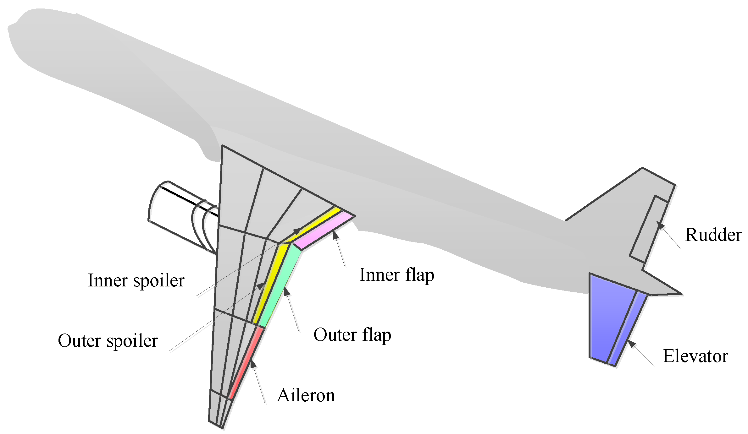
Motivated by the aforementioned observations, this paper focuses on the study of gust load alleviation control schemes for large civil aircraft, which have the same aerodynamic layout as the new generation wide-body dual-channel aircraft, with a length of 55 m, a wingspan of 50 m, and a maximum takeoff weight of 200 t. The main control surface configuration includes elevators, ailerons, and a rudder. The flaps are divided into inner flaps and outer flaps. Specifically, the spoiler is also divided into inner and outer spoilers. Figure 1 displays its aerodynamic layout illustration. On this basis, three control schemes are developed using a combination of variable wing camber technology and gust load alleviation functions. The core uses the pitch rate feedback to improve the short-period damping ratio and normal overload feedback to improve the short-period frequency. The presented schemes contribute to efficient cruise flight, gust load alleviation capability, and reduced wing structural weight, thereby improving the flight’s safety, economy, and comfort. Their engineering feasibility is aliged with the current status, technological maturity, and development level of China’s aviation industry, providing preliminary exploration for the application of a wide-body civil aircraft under development with wing curvature functions and independent control of the inner and outer flaps.
Figure 1. Schematic diagram of the considered civil aircraft.
Actuators 13 00229 g001

2. Preliminary Materials

Principle of Variable Wing Camber

During the cruise stage, the wing curvature distribution is adjusted through the differential control of the inner and outer flaps in order to minimize the flight drag force, enhance the lift–drag ratio of the aircraft, and improve the fuel efficiency. To describe the basic principle, the lift coefficient C L of the aircraft is first introduced and is expressed as
C L = L 0.5 ρ V 2 S
where L represents the lift, ρ is the air density, V is the true airspeed, and S is the wing reference area.
During long-term cruising, the fuel consumption of an aircraft can cause a change in weight of over 50% [1]. Assume that the aircraft is at its optimal aerodynamic efficiency state when the lift-to-drag ratio is at its maximum. When fuel consumption or an air drop mission leads to a decrease in aircraft weight, the required lift for longitudinal balance also decreases. Without changing the flight altitude and speed, or the wing area, according to Equation (1), it can be seen that the lift coefficient will also decrease, and the lift–drag ratio will gradually decrease, deviating from the designed optimal aerodynamic efficiency state. Currently, improving this situation involves continuously increasing the flight altitude so that the aircraft flies in a less dense atmosphere to increase the lift–drag ratio and return to its optimal state. However, for commercial aircraft, flight altitude is strictly controlled. For example, in the North Atlantic airspace, flight altitudes must be adjusted in steps of 1000 ft. Therefore, based on the above description, it can be concluded that during most of its cruising stage, an aircraft does not fly at its optimal aerodynamic efficiency [27].
Therefore, in view of the step-climb cruise mode, at each level of the flight segment, a given Mach number, a given converted weight (the ratio of aircraft weight to altitude pressure), and a given flight altitude are performed, while variable curvature control is performed to achieve cruise drag reduction and improve the aircraft’s range and other performance indicators. The cruising range is calculated using the Brickett equation [28], as shown below
S = a M K C e W b e g i n W e n d d W W
where a, M, K, and C e are the sound velocity, Mach number, lift–drag ratio, and fuel consumption per unit of engine thrust through unit time, respectively, and W b e g i n and W e n d denote the initial cruise weight and cruise end weight of the aircraft, respectively.
Usually the change in a and C e is small enough to be ignored. As can be seen from (2), in order to obtain the maximum flight range, it is necessary to find the maximum parameters, that is, cruise with the optimal cruise Mach number M o p t and the maximum lift–drag ratio K m a x . According to the polar curve of the aircraft at different Mach numbers, one can obtain K m a x . Consider a target aircraft with M o p t = 0.8 and whose cruising weight range is known to be 100 t∼160 t. Referring to the flight level configuration standard and based on conditions such as the equivalent conversion weight and aerodynamic data of the flap differential, the step height variation and wing deflection strategy can be obtained as shown in Figure 2.
Figure 2. Diagram of the target aircraft cruising with variable wing camber flight.
Actuators 13 00229 g002
The flap differential scheme is shown in Figure 2. It can also be considered to synchronize aileron deflection with the outer flap and use the spoiler to shield the gap caused by the flap movement at a small angle to achieve the closure of the airfoil profile [29], so as to further reduce the cruise drag force and improve the lift–drag ratio. When the aileron deflection scheme is adopted and the spoiler is deflected on the basis of aileron deflection, the optimization data of the target aircraft lift–drag ratio is obtained, as shown in Table 1.

3. Results

3.1. Existing Load Alleviation Logic Design Methods

To summarize the existing logic design methods for aircraft load alleviation, we can summarize them into the following steps:
Step 1: The feedback signal for longitudinal gust load alleviation control usually uses pitch rate and normal acceleration. Some schemes also use normal acceleration at the center of gravity and wing [30].
Step 2: The control surfaces used for load alleviation include ailerons, elevators, spoilers, flaps, etc.
Step 3: Permission restrictions need to be imposed on the control surface to avoid affecting the normal operation of the aircraft. For example, DHC-6 aircraft provides 40% of the ailerons and 20% of the elevators for gust alleviation.
Step 4: The activation condition of the gust load alleviation function when there is pilot control is related to the margin considered by the aircraft structure at the beginning of design. Reducing the gust loads can reduce the wing loads under atmospheric disturbances, thereby reducing the weight of wing structures and improving the fatigue life of the aircraft. To ensure safety, the structural stiffness of the aircraft needs to meet the maximum load-bearing requirements, and then the gust load alleviation function is used to reduce the wing weight and improve its fatigue life. To avoid overlapping maneuvers, it may be considered that this function is only used during steady-state flight when the pilot does not aggressively maneuver the aircraft. For instance, the A320 plan stipulates that the load alleviation function will activate if the difference between the system’s normal overload and the pilot’s control overload exceeds 0.3 g and persists for more than 5 s. Grumman Aerospace proposes suppressing this function during the pilot’s effective command period and activating it once the effective command ceases, for which the control flow diagram is shown in Figure 3.
Figure 3. The control flow diagram of the gust load alleviation function.
Actuators 13 00229 g003
Step 5: Filter design is required after the sensor, such as controlling the elevator through low-pass filters and washout networks for pitch and elevation rate signals. The feedback channel adopts a washout network to eliminate the influence of steady-state overload and pitch rate during turning [31]. The B751 aircraft showed that adding a high-pass filter to the overload feedback channel can improve long-term stability, and adding a low-pass filter to the elevator feedback channel can appropriately adjust the control quality.
Step 6: The implementation of this function largely relies on sensors with higher control surface deflection rates and smaller time delays. Higher control surface deflection rates need to be achieved by large bandwidth and high-power actuators, ensuring that the bandwidth of the control surface actuators used is greater than the bandwidth of the gust disturbances. Compared with the aircraft maneuverability requirements, active control systems require an increase in the speed of the control surface deflection. If the traditional system architecture of “centralized drive and coaxial transmission” is adopted for flap control, it is not possible to use flaps to achieve this function. However, this article carries out the design based on the wing variable curvature design architecture, but there will also be requirements for flap speed.
Step 7: When the gust load reduction function exits, it is necessary to consider setting a hysteresis loop for the exit condition to avoid oscillation problems caused by reciprocating forward and backward near the entry condition.
According to the above observations, a new gust load alleviation logic design will be carried out:
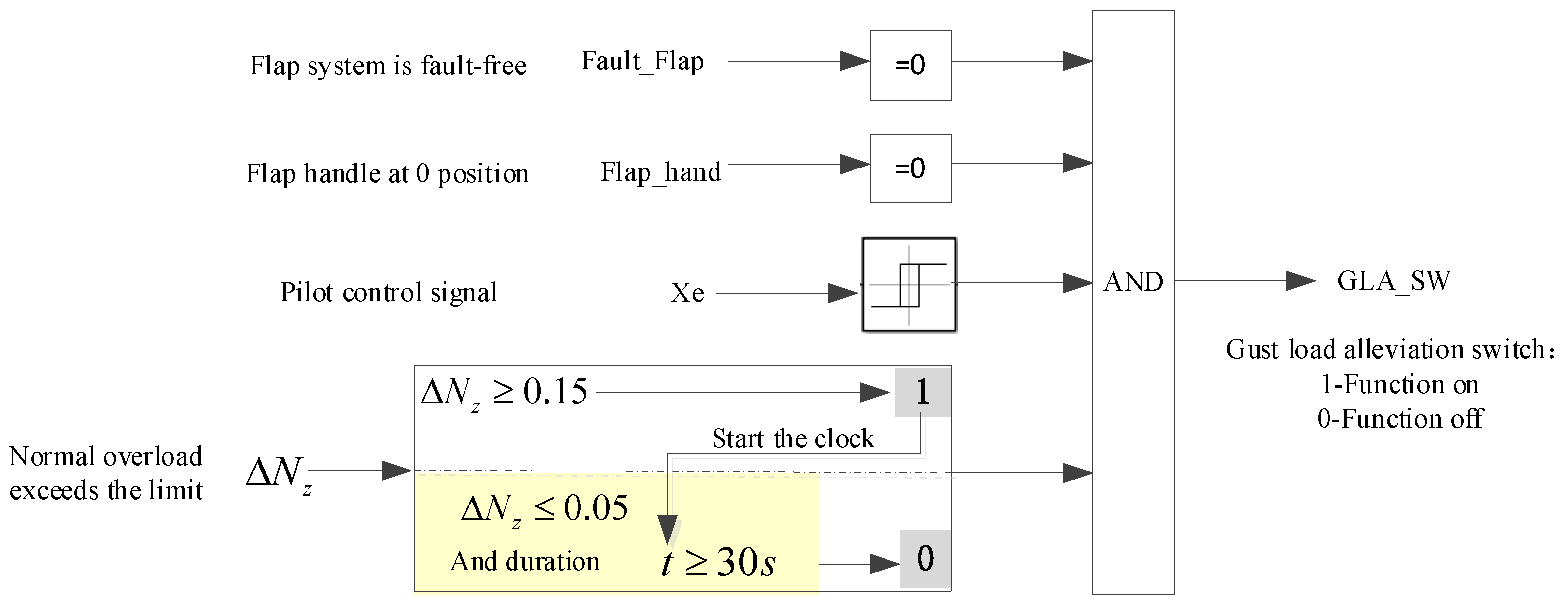
The logic design of the gust load alleviation function switch GLASW is shown in Figure 4. When there are no faults in the flap system, the flap handle is in the 0 position, there is no driver operation, the normal overload is exceeded, the gust load alleviation function is activated, and GLASW = 1. Otherwise, it will be closed; GLASW = 0.
Figure 4. The logic design of the gust load alleviation function.
Actuators 13 00229 g004
Specifically, when there is no driver control, hysteresis judgment is used in the logic design to prevent repeated logic switching due to signal jitter. When the longitudinal control lever command X e 2 mm, the output value is 0. When the longitudinal control lever command X e 0.5 mm, the output value becomes 1.
Furthermore, considering that normal overload may exceed the limit, in the design logic, when the change in normal overload Δ N z 0.15 occurs, the output value is 1, which means the gust load alleviation function is activated and timing begins. When the normal overload change Δ N z 0.05 and the timing time has been continuous for 30 s, the output value is 0, which means the gust load alleviation function is turned off. This hysteresis design mainly prevents the function from repeatedly turning on/off at the boundary value.

3.2. Load Alleviation Control Schemes

The gust load alleviation control approach provided in this paper is an outer loop design. Taking the longitudinal channel as an example, the considered aircraft adopts a typical PI architecture and C* control law configuration in the longitudinal channel. This configuration uses pitch rate feedback to improve the short-period damping ratio and normal overload feedback to increase the short-period frequency. The considered aircraft has a wing deflection function, and its core is that its inner and outer flaps can be controlled separately. To reduce the load, three control schemes are designed.
Control Scheme 1: Select the pitch rate and normal overload as the feedback signals. The inner flaps and elevators are selected as the control surfaces for the gust load alleviation system, and the control law schematic is shown in Figure 5. After passing the pitch rate signal through low-pass filtering and multiplying control gain, generate the elevator command δ e _ G L A and add it to the longitudinal channel output. Using normal overload as a feedback signal and passing through a high-pass filter and proportional-integral controller, an inner flap command ( F g i n ) is generated. In order to maintain that there are no gaps on the wing after flap movement, synchronous motion of the inner spoiler is added, and left and right inner spoiler commands of δ G s p _ l _ i n and δ G s p _ r _ i n , respectively, are generated.
Figure 5. Schematic diagram of the gust load alleviation control of Scheme 1; (a) elevator control channel; (b) flap control channel.
Actuators 13 00229 g005
The commands for the pitch rate and normal overload mentioned above are both output through a bidirectional attenuator to prevent transient changes during control law switching. The working principle of a bidirectional desalinator is as follows: when GLASW = 0, the output is 0. When GLASW = 1, the output is the rudder command. When GLASW is between 0 and 1, the output is a mixed command of 0 and the rudder surface. From a dynamic perspective, GLASW changes from 0 to 1, and the output transitions from 0 to the control surface command. GLASW changes from 1 to 0, and the output transitions from the control surface command to mode 0. The fading time of the transition process is selected as 1 s.
Control Scheme 2: Select the pitch rate and normal overload as the feedback signals. Select the outer flaps, ailerons, and elevators as the control surfaces for the gust load alleviation system. Among them, the principle of the pitch rate control is the same as Figure 5. Figure 6 shows the normal overload part of the wind load alleviation control law in this control scheme.
Figure 6. Schematic diagram of the gust load reduction control of Scheme 2.
Actuators 13 00229 g006
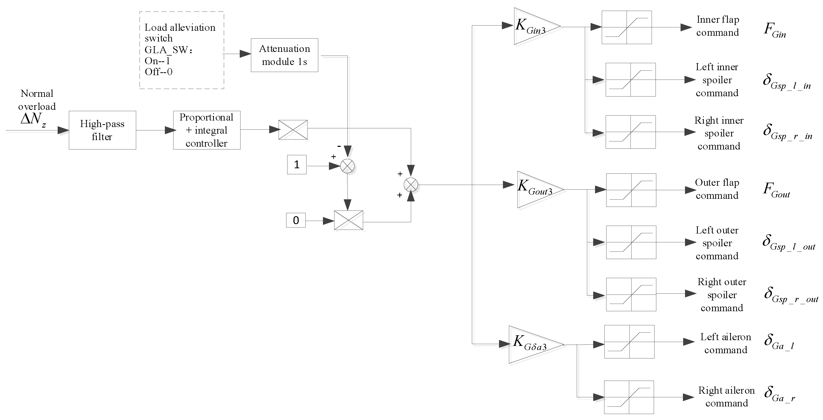
Control Scheme 3: Select the pitch rate and normal overload as the feedback signals. Select the inner flaps, outer flaps, ailerons, and elevators as the control surfaces for the gust load alleviation system. Figure 7 shows the normal overload part of the wind load alleviation control law for Scheme 3.
Figure 7. Schematic diagram of the gust load reduction control of Scheme 3.
Actuators 13 00229 g007

3.3. Functions Switching Logic Design
The cruise drag reduction and gust load alleviation functions are both designed based on control augmentation, and their output commands include flaps, ailerons, and spoilers.
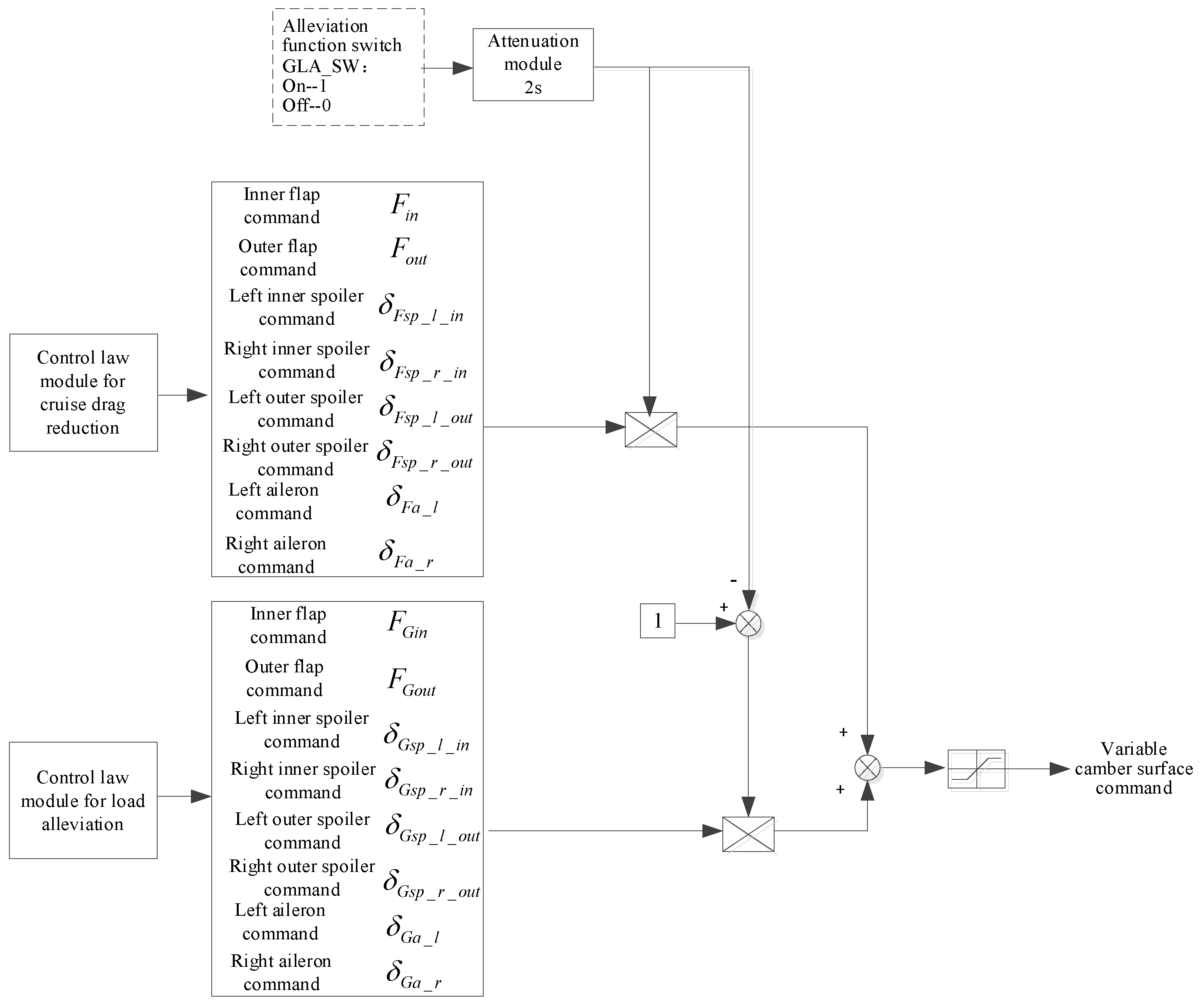
To avoid affecting the architecture of the original control law, the control laws for cruise drag reduction and gust load alleviation can be placed separately in one module, namely the variable curvature control module. Finally, the control surface commands output by this module can be superimposed on the control surface commands of the original flight control system. Therefore, it is necessary to switch the commands for cruise drag reduction and gust load alleviation inside the variable curvature control module.
When the gust load alleviation function activates, specifically when GLASW = 1, the drag reduction function transitions to VCWSW = 0, effectively disabling the cruise drag reduction function. For this purpose, the gust load alleviation switch GLASW is used as the switching command for the variable curvature control module command. The specific logic design is shown in Figure 8. When the alleviation function is not turned to GLASW = 0, output the rudder surface command for cruise drag alleviation control calculation. When the deceleration function is turned on, GLASW = 1; after being diluted for 2 s, the output is the rudder surface command for the gust load alleviation control. Within the 2 s fading time, the output is a mixed command.
Figure 8. Logic block diagram of the cruise drag reduction and load alleviation command output.
Actuators 13 00229 g008

4. Simulation Results

4.1. Wind Model

GJB2874-97 [32] specifies the type of atmospheric disturbance models, such as atmospheric turbulence, wind shear, mean wind, and discrete gusts. In terms of the flight stage and impact degree, the objects reducing gust loads are mainly atmospheric turbulence and discrete gusts. The atmospheric turbulence studied in this paper adopts the Dry-den spectral form and uses the turbulence scale and mean square value of wind speed suggested by MIL-HDBK-1797. The atmospheric intensity is selected as moderate 10 3 ; discrete gusts use the (1-cos) type. Before the 1980s, full wave models were mostly used, while after the 1980s, half wavelength models were more preferred [29]. This paper uses a half-wavelength model, with gust amplitudes set at 3.5 m/s.

4.2. Ride Quality

When the vertical vibration overload exceeds 0.1 g, passengers feel uncomfortable. When it exceeds 0.2 g, the instrument panel becomes difficult to read. When it exceeds 0.5 g and lasts for a few minutes, the pilot will worry about an accident and change the flight altitude and speed. The allowable value for lateral vibration overload is approximately half that of vertical overload. The riding quality indicators can be given as follows: the vertical acceleration should be limited to ±0.05 g and horizontal acceleration should be limited to ±0.02 g. Moreover, the above command variables should not be overshoot at heights greater than 1000 ft.
The most common criterion in engineering is the C criterion [33], and uses the mean square deviation parameter of aircraft atmospheric turbulence response to evaluate passengers’ riding experience. This paper adopts the C criterion for passenger quality evaluation, and the expression of the passenger comfort index is as follows
C = 2 + 11.9 a ¯ y + 7.6 a ¯ z
where a ¯ y is the root mean square value of the normal overload caused by turbulence for passengers and a ¯ z is the root mean square value of lateral overload. The relationship between ride comfort index C and ride quality evaluation is shown in Table 2.
The above evaluation is based on a survey conducted primarily on passenger planes [33]. If used as a military aircraft, a score of “5” should be used as the reference boundary for whether the riding quality requirements of the aircraft seriously distract the pilot’s combat energy. If the rating value falls within the range of “5”, it is considered to meet the requirements for riding quality; if it falls outside of this range, it is considered to not meet the requirements. This indicates that civil aircraft prioritize ride quality control.

4.3. Atmospheric Turbulence Is Considered in Simulation Case 1
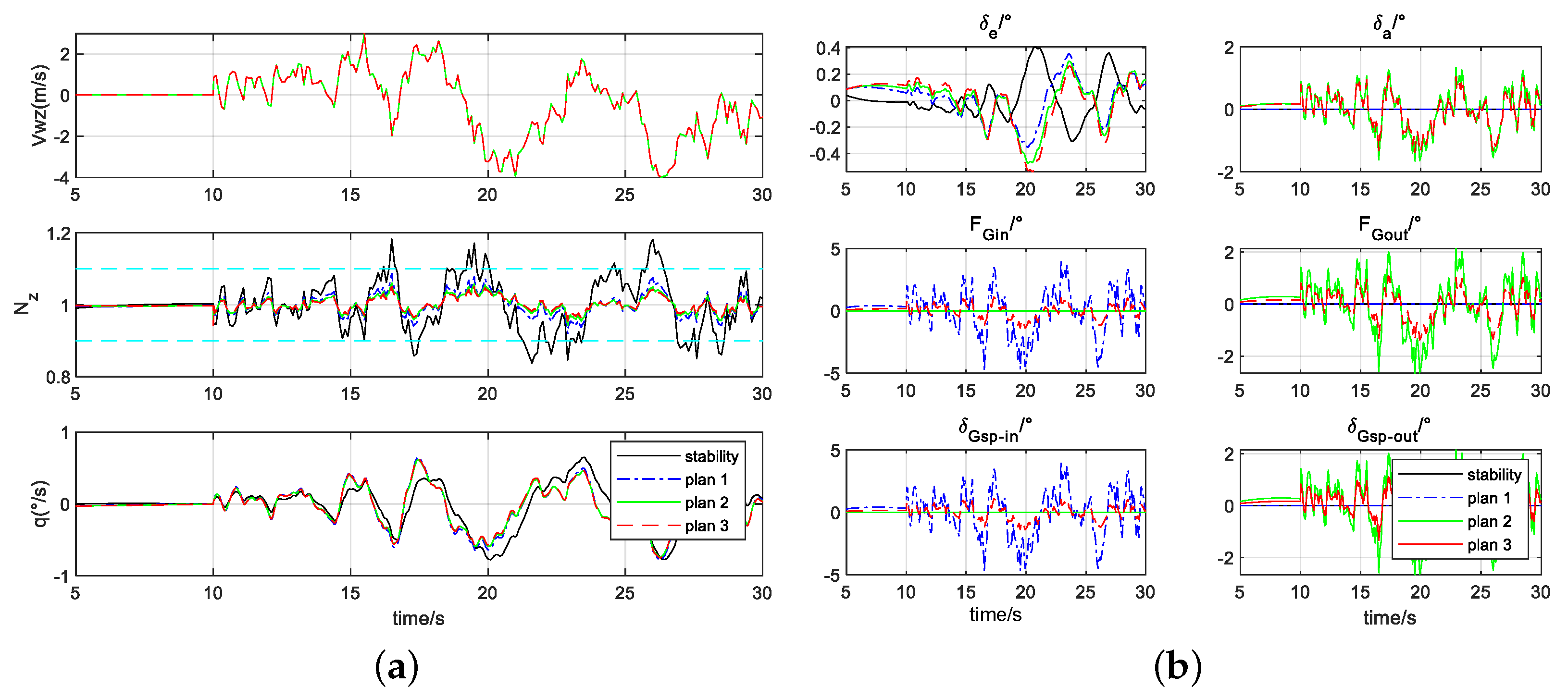
At 10 s, atmospheric turbulence disturbance is added, and the simulation of state point 1 in Table 1 is shown in Figure 9.
Figure 9. Simulation curve of atmospheric turbulence on P1. (a) The evolution of aircraft’s characteristic parameters; (b) The time response curves of the aircraft’s actuators.
Actuators 13 00229 g009
It is shown that when the turbulence intensity is high, the normal overload of the stabilization scheme will exceed 0.1 g. Scheme 1, Scheme 2, and Scheme 3 all control the normal overload within 0.1 g. The simulation data for atmospheric turbulence at 16 state points are shown in Table 3.
As shown in the table, the C value at each state point is less than 3, indicating a comfortable riding quality. Compared with the control of no gust load alleviation, the C value alleviation in Scheme 3 is the most significant. The root bending moment of the wing has relatively little alleviation control, and the percentage alleviation of each scheme is not significantly different. Scheme 1 has the most alleviation. If considering the premise of comfortable ride quality, Scheme 1 is optimal.

4.4. Discrete Gust Is Considered in Simulation Case 2

At 10 s, discrete gust disturbance is added, and the simulation of state point 4 in Table 1 is shown in Figure 10.
Figure 10. Simulation curve of discrete gust turbulence on P4. (a) The evolution of aircraft’s characteristic parameters; (b) The time response curves of the aircraft’s actuators.
Actuators 13 00229 g010
It can be seen that the stability enhancement scheme will have a normal overload exceeding 0.1 g when the gust intensity is high, as shown in Figure 10. Part of the state points in Scheme 1 will slightly exceed 0.1 g, while both Scheme 2 and Scheme 3 will control the normal overload within 0.1 g. The discrete gust simulation data for 16 state points are shown in Table 4.
The table reveals that each state point’s C value is less than 3, signifying a comfortable riding quality. Moreover, the C value of Scheme 3 shows the most significant percentage reduction compared with the control without gust alleviation. The percentage difference in the relative alleviation of the wing root bending moment without slowing down is not significant, with Scheme 3 demonstrating the most significant alleviation. If considering the premise of comfortable ride quality, Scheme 3 is optimal.
Summarizing the above simulation results in Section 4.3 and Section 4.4, the considered atmospheric turbulence and discrete gusts can, to some extent, represent the wind disturbance situations that civil aircraft may encounter during actual flight. Therefore, the simulation results can serve as a qualitative reference for selecting gust load alleviation schemes. The results reveal that the three control schemes offer comfortable ride quality, and there is no significant difference in the percentage reduction in wing root bending moment. Given that an increase in control surface will lead to a more complex control law design, thereby increasing software computation, the synchronous rapid motion of inner flaps, outer flaps, and ailerons will further complicate the design of actuators on each control surface. Based on the above considerations, this paper recommends Scheme 1.

4.5. Functions Logic Switching Simulation Test
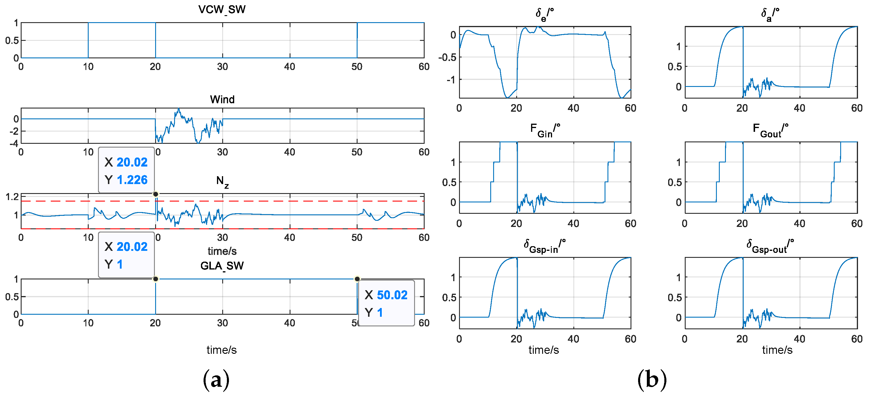
To observe the logical switching performance of the cruise drag reduction function and gust load alleviation function, taking state point 1 as an example, set the drag reduction switch VCWSW to change from 0 to 1 after 10 s of simulation, representing the activation of the drag reduction function in 10 s. Wind interference is added after 20 s of simulation and ended after 30 s. The simulation results are shown in Figure 11.
Figure 11. Cruise drag reduction and load reduction logic simulation results. (a) The evolution of logic switching; (b) The time response curves of the aircraft’s actuators.
Actuators 13 00229 g011
From Figure 11, it can be seen that at 10 s, VCWSW = 1, the drag reduction function is activated, and the inner and outer flaps, spoilers, and ailerons all move according to the optimal drag reduction control law. After adding wind disturbance at 20 s, the normal overload is greater than 1.15. At 20.02 s, the gust alleviation function is activated (the simulation step size is 0.02 s), and the gust load alleviation function switch GLASW changes from 0 to 1. At the same time, the drag reduction function is turned off, and the drag reduction switch VCWSW changes from 1 to 0. At 30 s, the wind disturbance is turned off, but due to the gust alleviation function setting a duration of 30 s, at 50.02 s, the gust alleviation function is turned off, the load alleviation function switch GLASW changes from 1 to 0, and the drag reduction function is turned on. The drag reduction switch VCWSW changes from 0 to 1, and the inner and outer flaps, deflectors, and ailerons move to 1.5° according to the optimal drag reduction control law. The overall simulation achieves the functional switching logic of the control law design.

5. Conclusions

Combining the current level and maturity of aviation technology development in China and focusing on the economic, safe, and comfort design requirements of civil aircraft, this paper developed three gust load alleviation control schemes based on variable curvature technology. Different control schemes for the flaps, ailerons, and spoilers were provided, and the benefits of gust load alleviation capability were analyzed. The simulation results showed that the designed control scheme could achieve the goal of improving the economic benefits and enhancing passenger riding quality. The findings in this paper can be employed as a guide for designing the wing variable curvature control system and making it easier to achieve gust load alleviation in engineering for the new generation of big wide-body civil aircraft. In addition, this work did not consider the feasibility analysis of gust load alleviation under structural elasticity and actuator fault conditions, which will be a focus of our future research work.

Author Contributions

Conceptualization, S.Z. and Y.Q.; methodology, S.Z. and J.S.; software, S.Z. and Z.G.; validation, B.W. and S.Z.; formal analysis, B.W.; investigation, Z.G.; resources, B.W.; writing—original draft preparation, S.Z.; writing—review and editing, S.Z. and B.W.; visualization, S.Z. and Z.G.; supervision, Y.Q. and J.S. All authors have read and agreed to the published version of the manuscript.

Funding

This research received no external funding.

Data Availability Statement

Datasets available upon request from the authors.

Acknowledgments

The authors sincerely thank the editors and reviewers for their kind attention and valuable comments dedicated to this paper.

Conflicts of Interest

Author Junshuai Sun was employed by the Qing’an Group Co., Ltd. The remaining authors declare that the research was conducted in the absence of any commercial or financial relationships that could be construed as potential conflicts of interest.

References

  1. Concilio, A.; Dimino, I.; Pecora, R. SARISTU: Adaptive trailing edge device (ATED) design process review. Chin. J. Aeronaut. 2021, 34, 187–210. [Google Scholar] [CrossRef]
  2. Rivero, A.E.; Weaver, P.M.; Cooper, J.E.; Woods, B.K.S. Parametric structural modelling of fish bone active camber morphing aerofoils. J. Intell. Mater. Syst. Struct. 2018, 29, 2008–2026. [Google Scholar] [CrossRef]
  3. Nguyen, N.; Cramer, N.; Hashemi, K.; Ting, E.; Drew, M.; Wise, R.; Boskovic, J.; Precup, N.; Mundt, T.; Livne, E. Real-time adaptive drag minimization wind tunnel investigation of a flexible wing with variable camber continuous trailing edge flap system. In Proceedings of the AIAA Aviation 2019 Forum, Dallas, TX, USA, 17–21 June 2019; pp. 1–47. [Google Scholar]
  4. Shen, G.; Bai, J.; Liu, N.; Liu, R. Mechanical simulation and aerodynamic analysis on a new type of wing trailing edge variable camber. J. Northwestern Polytech. Univ. 2016, 34, 578–586. [Google Scholar]
  5. Liu, R.; Bai, J.; Qiu, Y.; Li, Y. Design and analysis of variable camber wing of propeller aircraft using the actuator disc method. Aeronaut. J. 2022, 126, 2134–2155. [Google Scholar] [CrossRef]
  6. Szodruch, J. The influence of camber variation on the aerodynamics of civil transport aircraft. In Proceedings of the AlAA 23rd Aerospace Sciences Meeting, Reno, NV, USA, 14–17 January 1985; p. 0353. [Google Scholar]
  7. Kang, N.; Shi, Y. Variable camber differential flap technology applied in aircraft high lift system. In Proceedings of the 2018 CSAA/IET International Conference on Aircraft Utility Systems, Guiyang, China, 19–22 June 2018; pp. 160–164. [Google Scholar]
  8. Struber, H. The aerodynamic design of the A350 XWB-900 high lift system. In Proceedings of the 29th Congress of the International Council of the Aeronautical Sciences, St. Petersburg, Russia, 7–12 September 2014; pp. 1–6. [Google Scholar]
  9. Liu, F.; Li, X.; Dou, G.; Nie, R. A design of tandem drive variable camber wing and analysis of aerodynamic performance. J. Air Force Eng. Univ. 2024, 25, 62–68. [Google Scholar]
  10. Rajagopal, S.; Ganguli, R. Multidisciplinary design optimization of long endurance unmanned aerial vehicle wing. CMES—Comput. Model. Eng. Sci. 2011, 81, 1–34. [Google Scholar]
  11. Wang, W.; Feng, H.; Liu, C.; Huang, R. Aerodynamic optimization for multi-parameter variable-camber airfoil. Sci. Technol. Eng. 2024, 24, 1259–1267. [Google Scholar]
  12. Zhang, Y.; Ge, W.; Zhang, Z.; Mo, X.; Zhang, Y. Design of compliant mechanism-based variable camber morphing wing with nonlinear large deformation. Int. J. Adv. Robot. Syst. 2019, 16, 1–19. [Google Scholar] [CrossRef]
  13. Lei, C.; Yang, C.; Song, C. Optimization design of active aeroelastic wing with variable camber. J. Beijing Univ. Aeronaut. Astronaut. 2024, 1–11. [Google Scholar] [CrossRef]
  14. Pecora, R.; Concilio, A.; Dimino, I.; Amoroso, F.; Ciminello, M. Structural design of an adaptive wing trailing edge for enhanced cruise performance. In Proceedings of the 24th AIAA/AHS Adaptive Structures Conference, San Diego, CA, USA, 12–16 June 2016; pp. 1–12. [Google Scholar]
  15. Shi, X.; Yang, Y.; Ge, W.; Wang, Z.; Sun, X. Structure design of variable camber wing trailing edge based on multi-block rotating mechanism. J. Northwestern Polytech. Univ. 2023, 41, 942–949. [Google Scholar] [CrossRef]
  16. Zhou, Y.; Wu, Z.; Yang, C. Gust alleviation and wind tunnel test by using combined feedforward control and feedback control. Aerospace 2022, 9, 225. [Google Scholar] [CrossRef]
  17. Wang, X.; Mkhoyan, T.; Mkhoyan, I.; De Breuker, R. Seamless active morphing wing simultaneous gust and maneuver load alleviation. J. Guid. Control Dyn. 2021, 44, 1649–1662. [Google Scholar] [CrossRef]
  18. Mengali, G.; Pieracci, A. Ride quality of civil aircraft from a probabilistic viewpoint. J. Guid. Control Dyn. 2000, 23, 319–324. [Google Scholar] [CrossRef]
  19. Bernhammer, L.O.; Teeuwen, S.P.; De Breuker, R.; Van Der Veen, G.J.; Van Solingen, E. Gust load alleviation of an unmanned aerial vehicle wing using variable camber. J. Intell. Mater. Syst. Struct. 2014, 25, 795–805. [Google Scholar] [CrossRef]
  20. Zhao, D.; Yang, Z.; Zeng, X.; Yu, J.; Gao, Y.; Huang, G. Wind tunnel test of gust load alleviation for a large-scale full aircraft model. Chin. J. Aeronaut. 2023, 36, 201–216. [Google Scholar] [CrossRef]
  21. Liu, X.; Sun, Q. Improved LQG method for active gust load alleviation. J. Aerosp. Eng. 2017, 30, 04017006. [Google Scholar] [CrossRef]
  22. Zeng, X.; Zhao, D.; Li, J.; Yan, Z.; Liu, C. Wind tunnel test on gust alleviation control strategies of elastic wing. Acta Aeronaut. Astronaut. Sin. 2023, 44, 220–230. [Google Scholar]
  23. Wu, Z.; Cao, Y.; Ismail, M. Heavy rain effects on aircraft longitudinal stability and control determined from numerical simulation data. Proc. Inst. Mech. Eng. Part G J. Aerosp. Eng. 2015, 229, 1824–1842. [Google Scholar] [CrossRef]
  24. Thorsen, A.T.; Horn, J.F.; Ozdemir, G.T. Use of redundant controls to enhance transient response and handling qualities of a compound rotorcraft. In Proceedings of the 70th American Helicopter Society International Annual Forum, Montreal, QC, Canada, 20–22 May 2014; pp. 3085–3098. [Google Scholar]
  25. Wang, Y.; Li, F.; Da Ronch, A. Flight testing adaptive feedback/feedforward controller for gust loads alleviation on a flexible aircraft. In Proceedings of the AIAA Atmospheric Flight Mechanics Conference, San Diego, CA, USA, 13–17 June 2016; pp. 1–7. [Google Scholar]
  26. Khalil, A.; Fezans, N. Gust load alleviation for flexible aircraft using discrete-time preview control. Aeronaut. J. 2021, 125, 341–364. [Google Scholar] [CrossRef]
  27. Wang, B.; Yang, Y.; Qian, Z.; Wang, Z.; Lyu, S.; Sun, X. Technical development of variable camber wing: Review. Acta Aeronaut. Astronaut. Sin. 2022, 43, 144–163. [Google Scholar]
  28. Huang, T. Aircraft Performance Engineering; Science Press: Beijing, China, 2005; pp. 52–63. [Google Scholar]
  29. Nguyen, N.; Precup, N.; Urnes Sr., J.; Nelson, C.; Lebofsky, S.; Ting, E.; Livne, E. Experimental investigation of a flexiblewing with a variable camber continuous trailing edge flap design. In Proceedings of the 32nd AIAA Applied Aerodynamics Conference, Atlanta, GA, USA, 16–20 June 2014; pp. 1–13. [Google Scholar]
  30. Yuan, G.; Li, A.; Wang, C.; Xu, X. Gust alleviation control system design of large civil aircraft based on multiple control surfaces. Flight Dyn. 2011, 29, 65–67. [Google Scholar]
  31. Qu, X.; Li, T. Design of gust load alleviation control based on UD-PSO for civil aircraft. In Proceedings of the 5th International Conference on Advanced Algorithms and Control Engineering, Sanya, China, 20–22 January 2022; pp. 1–9. [Google Scholar]
  32. Commission of Science Technology and Industry for National Defense. Flying Qualities Standard for Airplane with Fly-by-Wire Control System: GJB 2874-97; Commission of Science Technology and Industry for National Defense: Beijing, China, 1997.
  33. Sun, Q. Calculation of passenger quality response of a large aircraft under atmospheric turbulence. Flight Dyn. 1984, 1, 61–82. [Google Scholar]
  34. Qu, X.; Wang, N. Probabilistic index and calculation of ride quality for civil aircraft. Acta Aeronaut. Astronaut. Sin. 2007, 6, 1323–1326. [Google Scholar]
Table 1. Comparison data of cruise wing varying camber lift–drag ratio.
State PointHeight (m)Weight (t)Lift CoefficientLift-Drag RatioOuter Flap ( ° )Inner Flap ( ° )Varying Camber Lift-Drag RatioAileronSpoiler
P191141600.53105315.7901.51.516.36116.45116.523
P291141530.50790715.5560.51.015.83415.91816.000
P391141460.48475415.3070.50.515.36115.36915.448
P497541460.53051115.7851.51.516.35816.44316.516
P597541400.50879115.5650.51.015.84015.93016.012
P697541330.48344415.2920.50.515.34315.35015.429
P710,3631330.52991415.7791.51.516.35516.43516.507
P810,3631270.50609815.5370.51.015.82215.89315.975
P910,3631210.48227515.2790.50.515.32715.33415.411
P1010,9731210.52949915.7751.51.516.35216.42916.502
P1110,9731150.50334115.5080.51.015.80415.85515.937
P1210,9731100.48153615.2710.50.515.31715.32315.401
P1311,5821100.52913115.7711.51.516.35116.42416.497
P1411,5821050.50517015.5270.51.015.81615.88015.962
P1511,5821000.48120115.2670.50.515.31215.31915.396
P1612,1921000.52876415.7671.51.516.34816.41816.491
Table 2. The relationship between passenger comfort index and ride quality evaluation [34].
RangeRide Quality Rank
2 ≤ C < 3Comfortable
3 ≤ C < 4Moderatly comfortable
4 ≤ C < 5Not comfortable
C ≤ 5Very uncomfortable
Table 3. Comparison of data from different schemes (atmospheric turbulence).
State
Point
Passenger Comfort
Index C-Value
Alleviation of Wing Root Bending Moment
(Relative Increase in Stability%)
Increase Stability Scheme 1 Scheme 2 Scheme 3 Scheme 1 Scheme 2 Scheme 3
P12.0702.0112.0062.00415.07413.86413.634
P22.0762.0112.0062.00415.03513.78513.666
P32.0822.0122.0062.00414.98713.67313.664
P42.0652.0102.0052.00415.08413.97713.760
P52.0702.0102.0052.00415.04913.90713.791
P62.0762.0112.0062.00415.00013.79213.793
P72.0602.0092.0052.00315.08714.07013.864
P82.0652.0092.0052.00415.05013.99613.899
P92.0702.0102.0052.00415.00513.89013.898
P102.0572.0092.0042.00315.07214.09613.892
P112.0622.0092.0052.00315.02814.01013.925
P122.0672.0092.0052.00414.98313.90813.918
P132.0562.0092.0042.00315.05314.08813.883
P142.0602.0092.0052.00315.00714.00613.909
P152.0662.0092.0052.00314.95113.88813.895
P162.0482.0082.0042.00315.11314.20613.988
Table 4. Comparison of data from different schemes (discrete gusts).
State
Point
Passenger Comfort
Index C-Value
Alleviation of Wing Root Bending Moment
(Relative Increase in Stability%)
Increase Stability Scheme 1 Scheme 2 Scheme 3 Scheme 1 Scheme 2 Scheme 3
P12.0392.0082.0052.00316.19015.13217.228
P22.0422.0082.0052.00416.13014.83217.068
P32.0452.0082.0052.00416.05514.48916.872
P42.0412.0082.0052.00416.19515.11217.223
P52.0442.0082.0052.00416.13814.82817.071
P62.0472.0092.0052.00416.05414.44816.851
P72.0432.0082.0052.00416.22715.10117.244
P82.0462.0092.0052.00416.16514.78217.073
P92.0492.0092.0062.00416.08414.41416.859
P102.0462.0092.0052.00416.31115.10517.316
P112.0492.0102.0062.00416.24414.74517.124
P122.0532.0102.0062.00516.17214.39616.922
P132.0492.0102.0062.00416.42815.12017.423
P142.0522.0102.0062.00516.37514.78617.250
P152.0562.0112.0062.00516.30214.39617.031
P162.0472.0102.0062.00415.77714.50716.706
Disclaimer/Publisher’s Note: The statements, opinions and data contained in all publications are solely those of the individual author(s) and contributor(s) and not of MDPI and/or the editor(s). MDPI and/or the editor(s) disclaim responsibility for any injury to people or property resulting from any ideas, methods, instructions or products referred to in the content.