A Novel Continuously Variable Transmission with Circumferentially Arranged Disks (CAD CVT)
Abstract
1. Introduction
2. Materials and Methods
2.1. Problem Statement
2.2. Design Conception
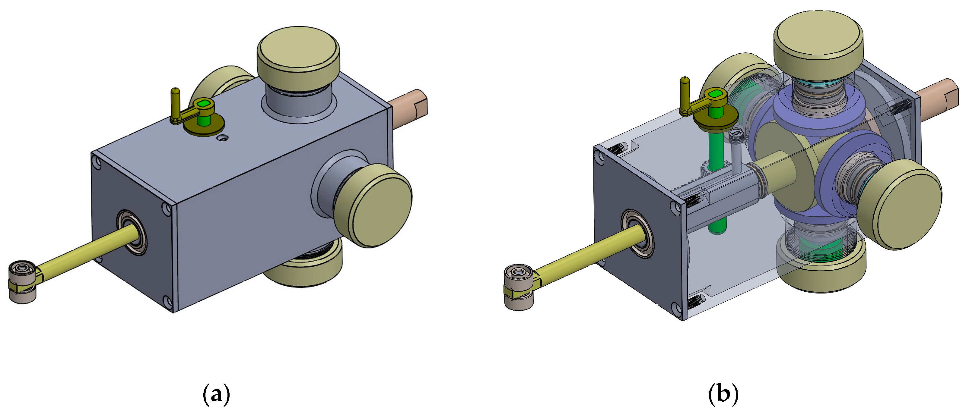
2.2.1. 3D Model
2.2.2. Configuration
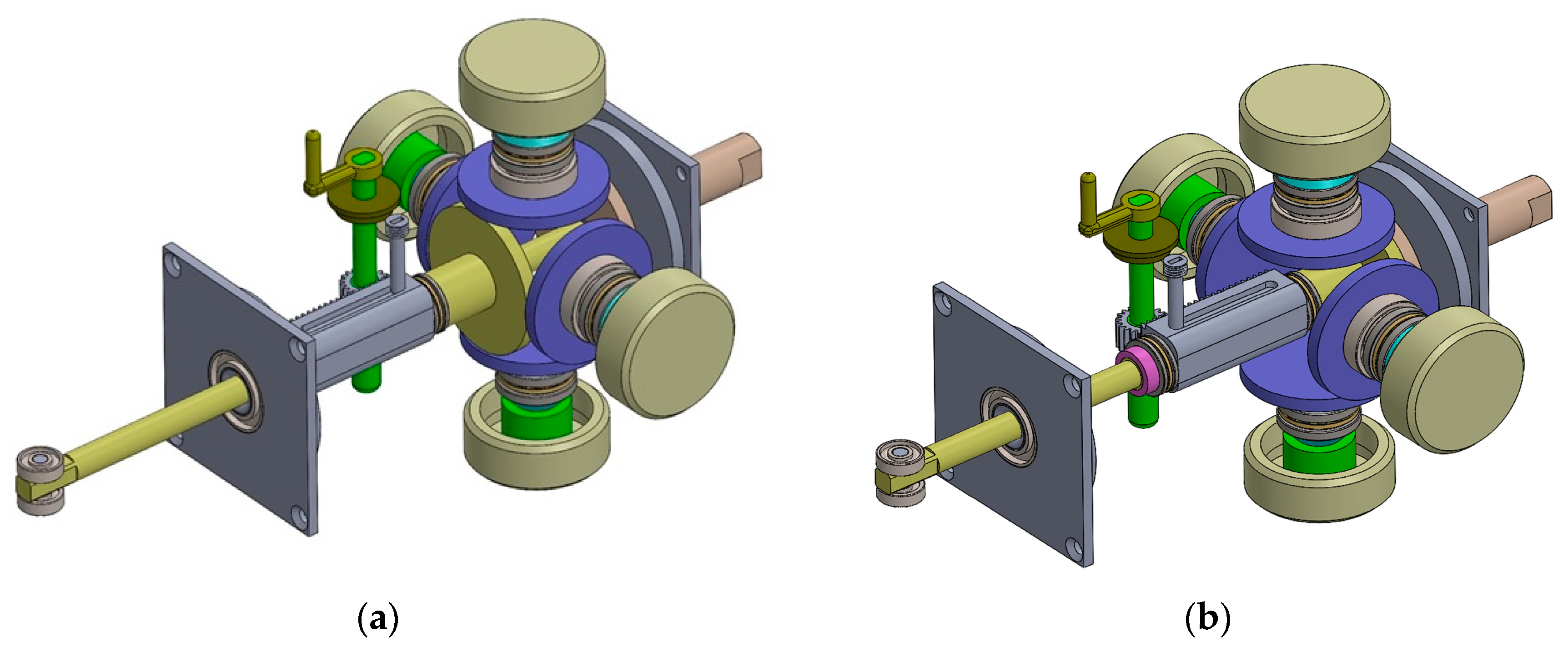
2.2.3. Operating Principle
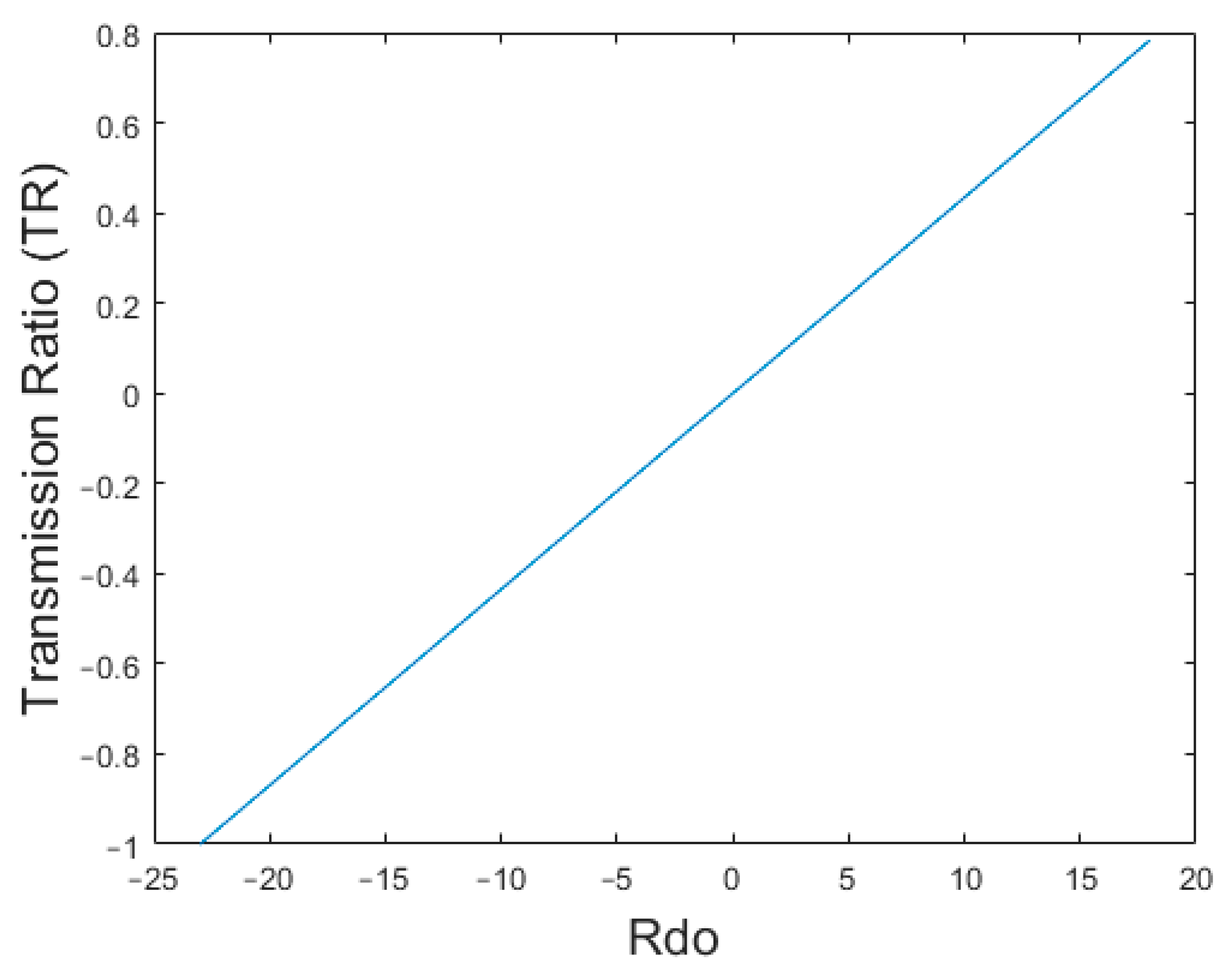
2.3. Transmission Ratio
- Rdi1 = Distance between Circumferentially Arranged Disk (CAD) no 1 and the traction point of CAD 1 with the input disk.
- Rdi2 = Distance between Circumferentially Arranged Disk (CAD) no 2 and the traction point of CAD 2 with the input disk.
- Rdin = Distance between Circumferentially Arranged Disk (CAD) no n and the traction point of CAD n with the input disk.
- Rdo1 = Distance between Circumferentially Arranged Disk (CAD) no 1 and the traction point of CAD 1 with the output disk.
- Rdo2 = Distance between Circumferentially Arranged Disk (CAD) no 2 and the traction point of CAD 2 with the output disk.
- Rdon = Distance between Circumferentially Arranged Disk (CAD) no n and the traction point of CAD n with the output disk.
- ωd1 = speed of CAD 1.
- ωd2 = speed of CAD 2
- ωdn = speed of CAD n.
- ωin = speed of input disk/input shaft.
- ωout = speed of output disk/output shaft.
2.4. Torque Capacity
- n = number of circumferentially arranged disks.
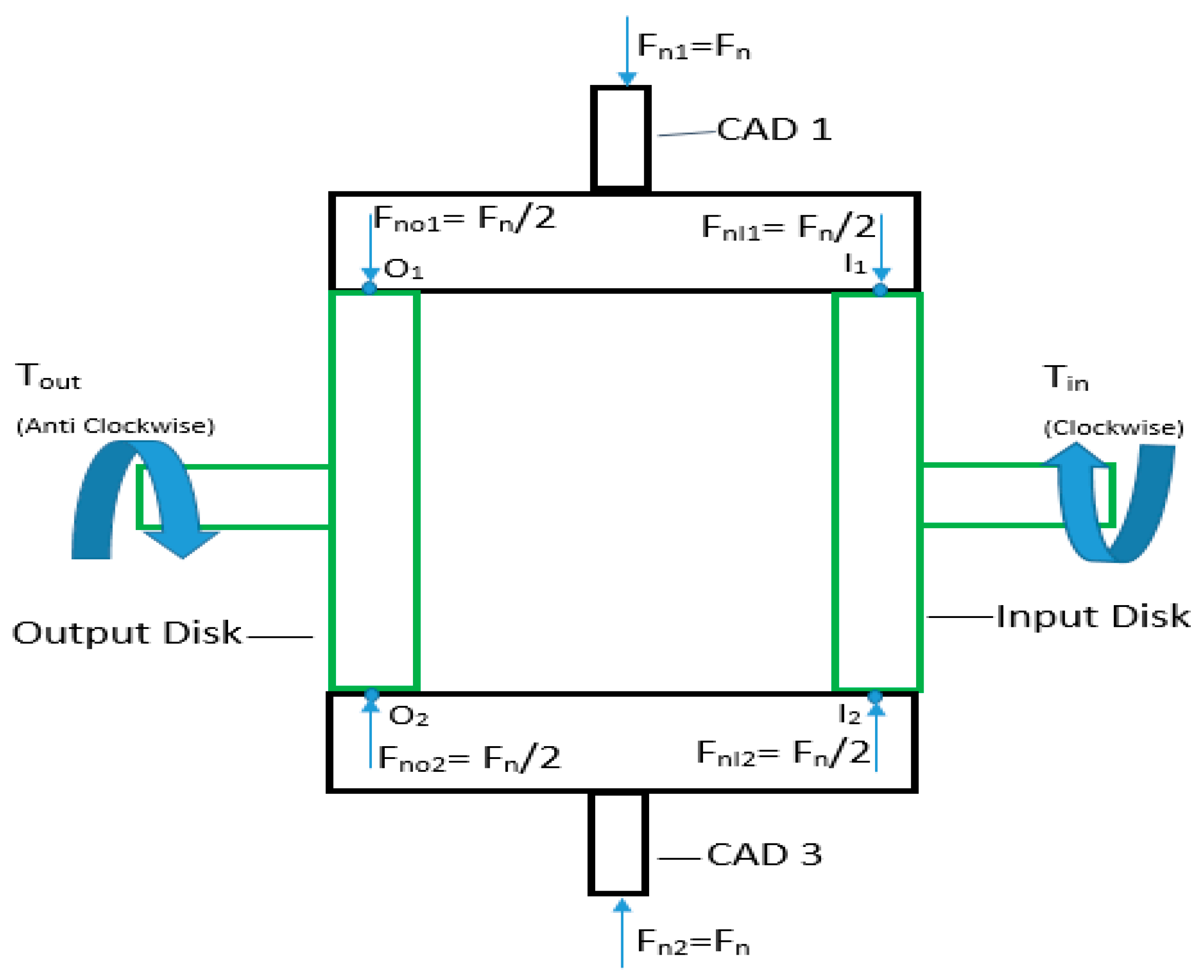
- Ro = Radius of output disk.
- Fn = Load applied to CADs.
- μkt = Coefficient of Kinematic traction of the material of which CAD and output disk is made.
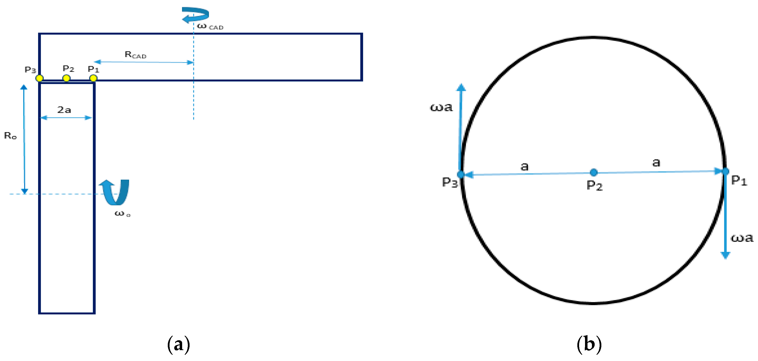
2.5. Frictional Losses and Efficiency
2.5.1. Spin Losses
2.5.2. Rolling Friction Losses
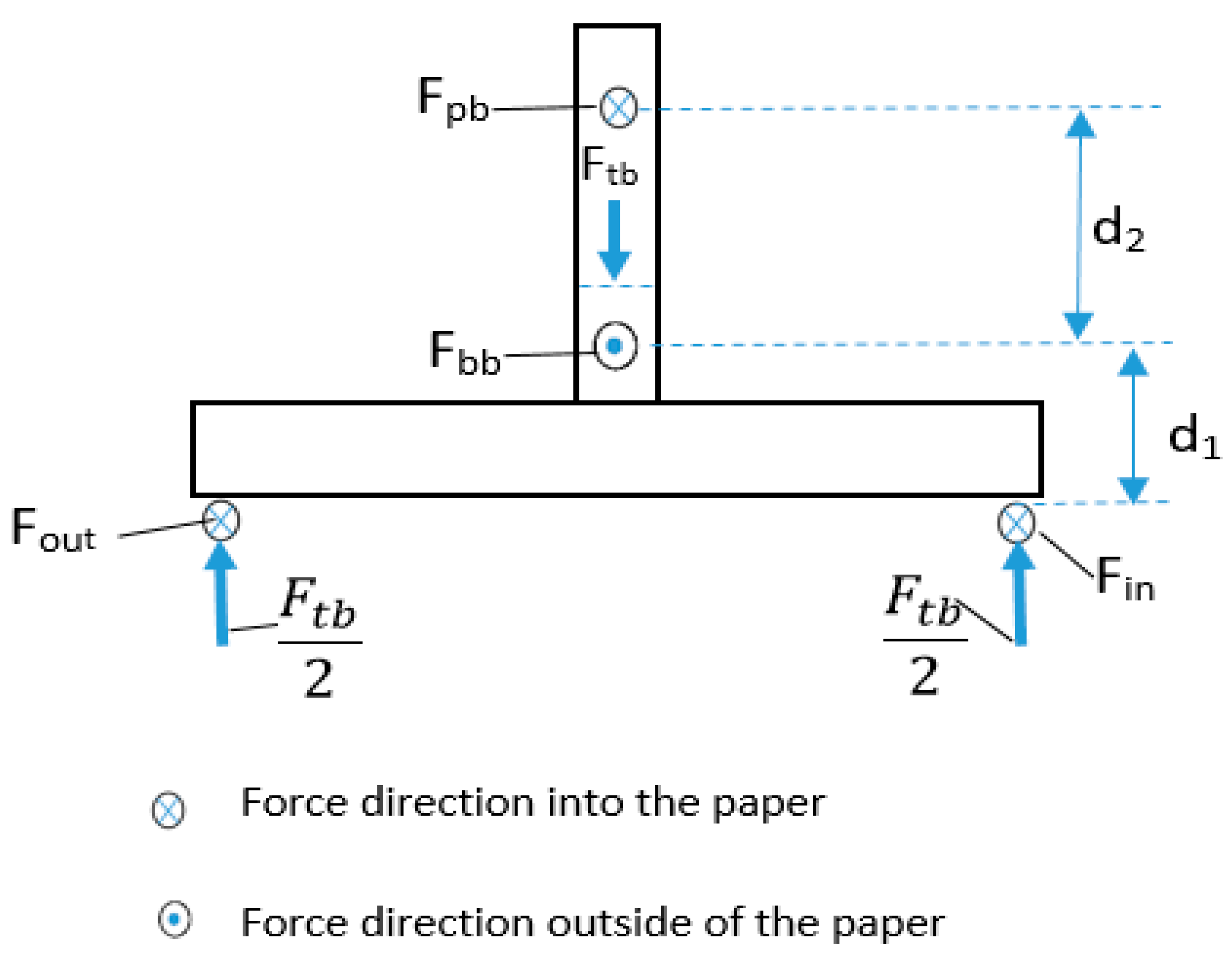
2.5.3. Bearing Losses
- To = torque at the output shaft.
- Tomax = maximum torque that can be supported by the output shaft.
- Tin = torque at the input shaft.
- Fout = Force applied by output disk on CAD at the traction point.
- Fin = Force applied by input disk on CAD at traction point.
- Fbb = Force applied by ball bearing on CAD.
- Fpb = Force applied by pin bearing on CAD.
- Ftb = Force applied by thrust bearing on CAD.
- Rbb = Radius of ball bearing.
- Rpb = Radius of pin Bearing.
- Rtb = Radius of thrust bearing.
2.5.4. Total Frictional Losses
- = Toatal power losses due to friction.
- = Power loss due to spin at tractive contact of input disk and CAD.
- = Power loss due to spin at tractive contact of output disk and CAD.
- = Power loss due to rolling friction at tractive contact of input disk and CAD.
- = Power loss due to rolling friction at tractive contact of input disk and CAD.
- = Power loss in ball bearing supporting CAD.
- = Power loss in pin bearing supporting CAD.
- = Power loss in thrust bearing supporting CAD.
- Number of CAD in the CVT.
2.5.5. Efficiency
2.6. Contact Pressure
- F = Force applied.
- L = length of Cylinder.
- E = Elastic moduli of the Material (210 GPa for steel).
- v = Poison Ratio (0.3 for steel).
- L = Length of cylinder.
- d = diameter of the cylinder (0.052 m for the CAD CVT designed in this article.)
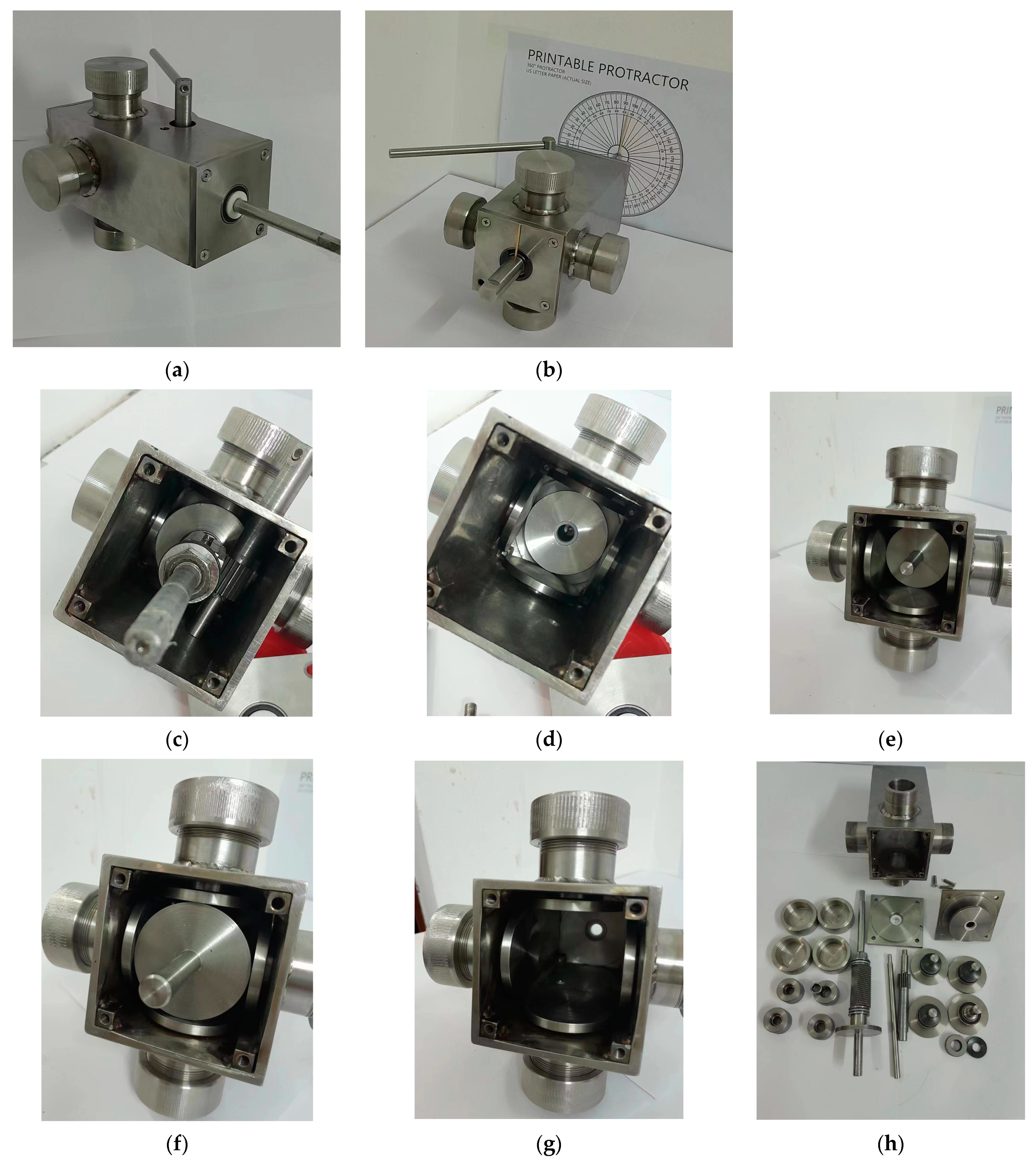
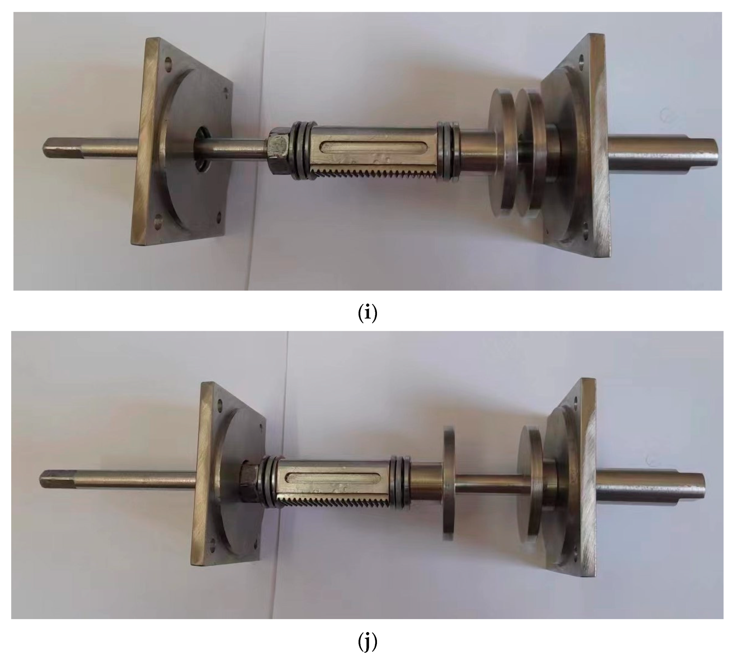
2.7. Experimental Validation/Proof of Concept
- The CAD CVT should provide a continuum of gear ratios between two points.
- The CAD CVT should be able to provide positive, negative, and neutral gear ratios without the requirement of an additional gear set.
- Step 1: Displace the output shaft fully outward through the gear ratio changing lever.
- Step 2: Measure the length of the output shaft.
- Step 3: Rotate the input shaft by 360o (2π).
- Step 4: Measure the corresponding rotation of the output shaft.
- Step 5: Displace the output shaft inward by 2 mm.
- Step 6: If the output shaft cannot be displaced further, then move to step 7; otherwise, return to step 2.
- Step 7: End.
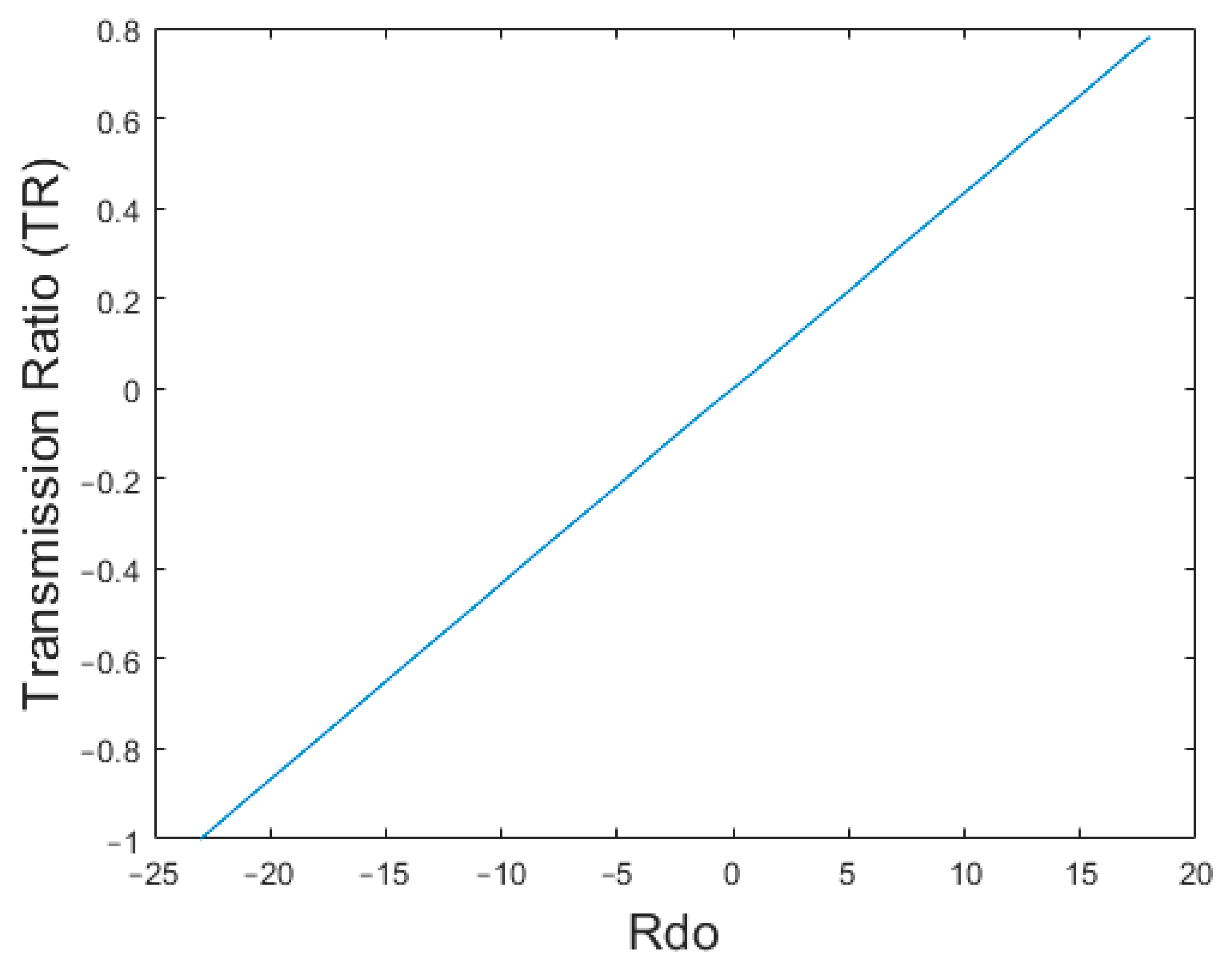
3. Results and Discussion
4. Conclusions
- The CAD CVT can achieve a reverse gear ratio and a neutral gear ratio without requiring an additional gear set.
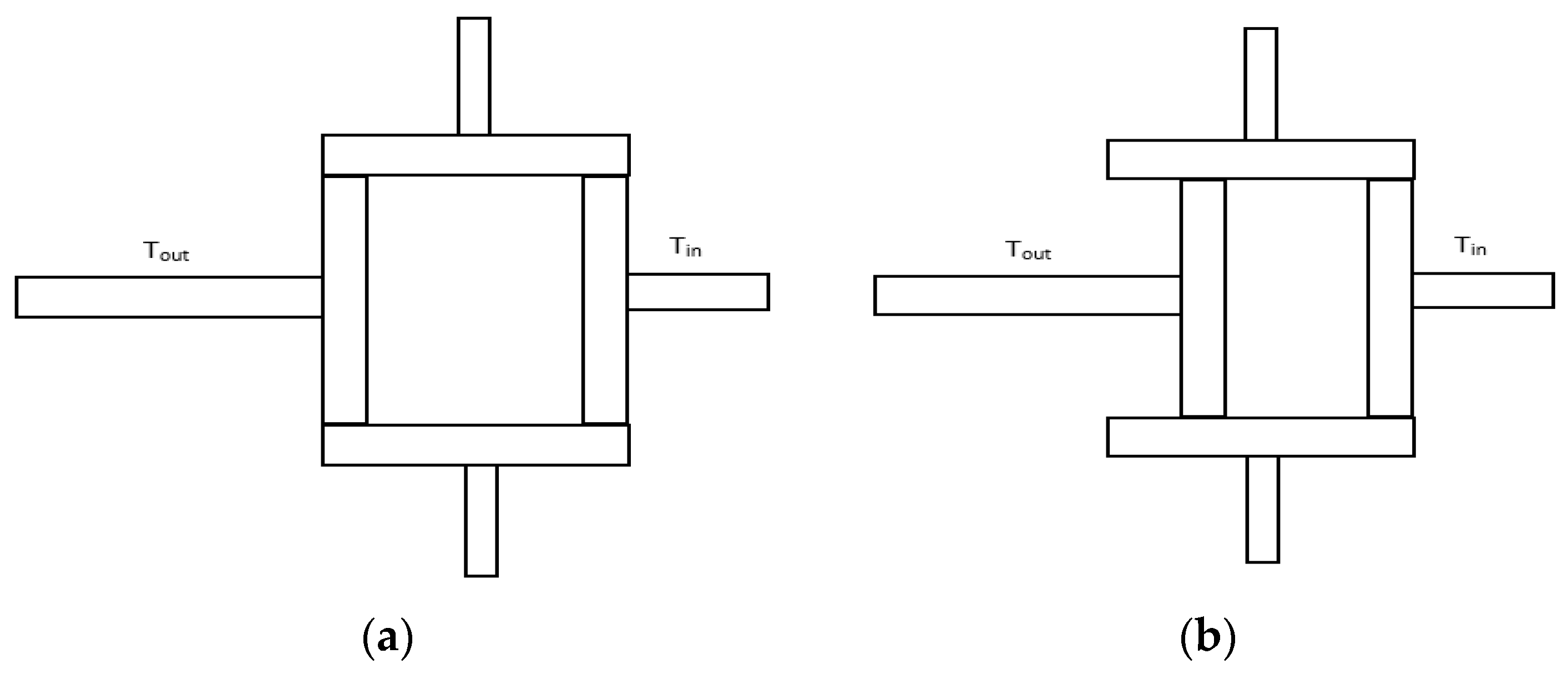
- The CAD CVT can have any number of CADs.
- The CAD CVT can be designed to either have point contact or line contact at its traction points. Point contact can be achieved by changing the contact line at the input and output disks from linear to circular shape. Point contact will provide higher efficiency but lower torque capacity, whereas line contact will provide higher torque capacity but lower efficiency.
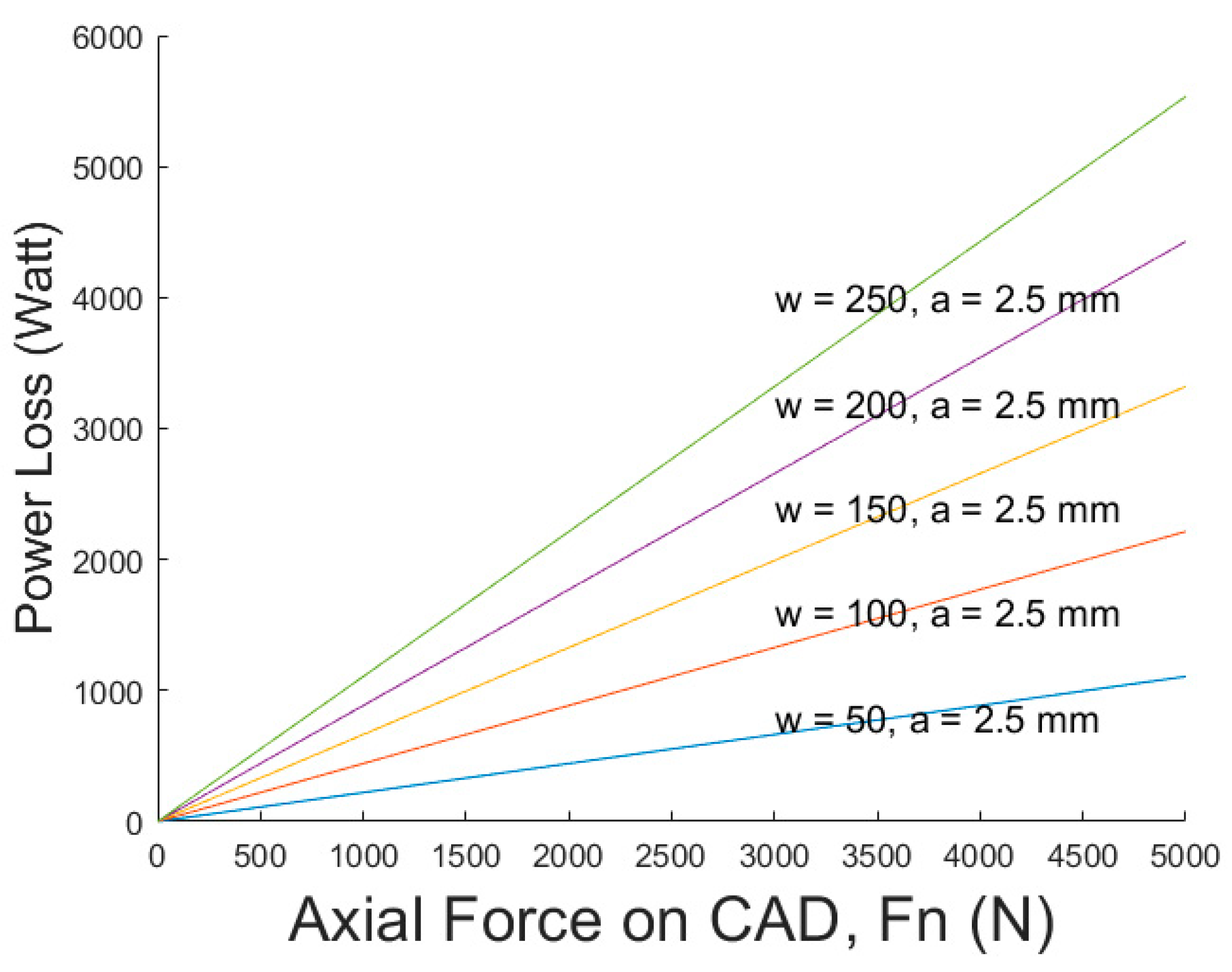
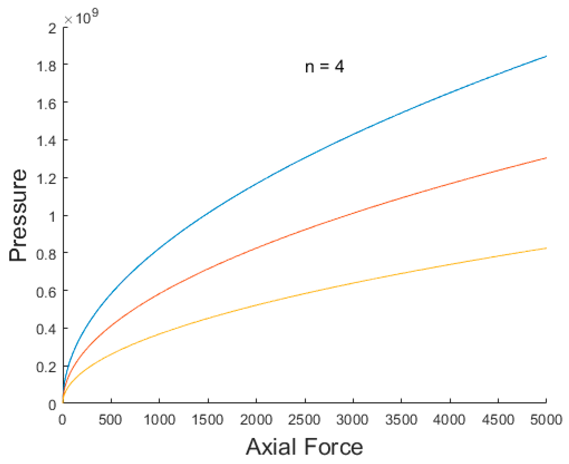
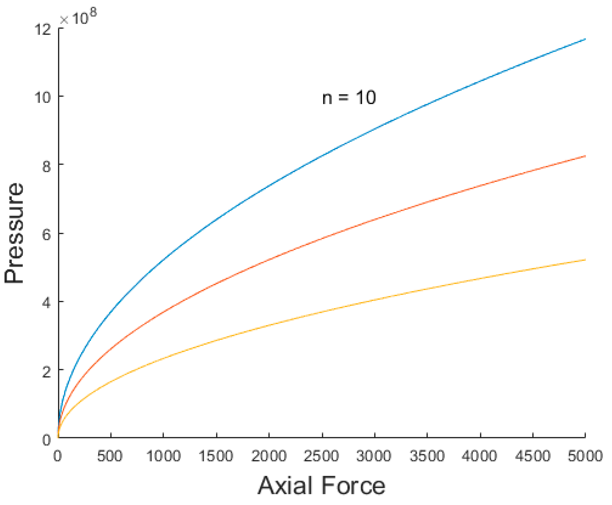
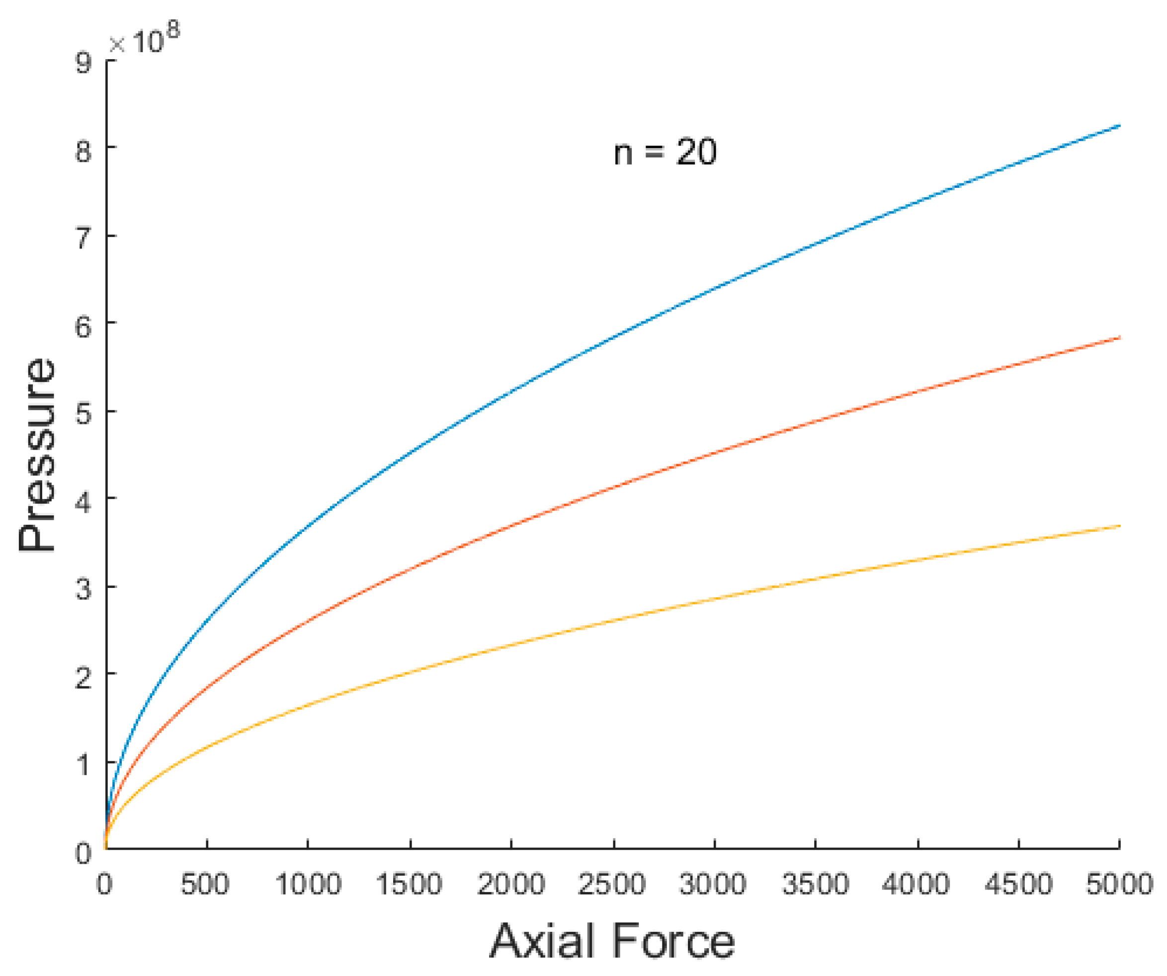
- The CAD CVT can be designed for both high-torque and low-torque applications. As per the simulation results shown in Figure 9, a CAD CVT with n = 10 CADs can achieve a torque capacity of 572 Nm, and with n = 20, it can achieve a torque capacity of 2291 Nm. This is much higher than the commercially available CVTs, i.e., the Push Belt CVT (250 Nm) and Toroidal CVT (450 Nm).
- The complexity of the gear-changing mechanism of the CAD CVT is independent of the number of CADs and the number of traction points.
Author Contributions
Funding
Data Availability Statement
Conflicts of Interest
References
- Carbone, G.; Mangialardi, L.; Mantriota, G. A comparison of the performances of full and half toroidal traction drives. Mech. Mach. Theory 2004, 39, 921–942. [Google Scholar] [CrossRef]
- Ruan, J.; Walker, P.D.; Wu, J.; Zhang, N.; Zhang, B. Development of continuously variable transmission and multi-speed dual-clutch transmission for pure electric vehicle. Adv. Mech. Eng. 2018, 10, 1–15. [Google Scholar] [CrossRef]
- Jawad, Q.A.; Ali, A.K. Comparison of CVT Performance with the Manual and Automatic Transmission for Evaluation the Fuel Consumption and Exhaust Emissions. Basrah J. Eng. Sci. 2020, 20, 15–22. [Google Scholar] [CrossRef]
- Nguyen, V.H.; Do, T.C.; Ahn, K.K. Investigation and Optimization of Energy Consumption for Hybrid Hydraulic Excavator with an Innovative Powertrain. Actuators 2023, 12, 382. [Google Scholar] [CrossRef]
- Sheng, Y.; Escobar-Naranjo, D.; Stelson, K.A. Feasibility of Hydrostatic Transmission in Community Wind Turbines. Actuators 2023, 12, 426. [Google Scholar] [CrossRef]
- Cotrell, J. Assessing the Potential of a Mechanical Continuously Variable Transmission for Wind Turbines. WindPower 2005 Denver, Colorado May 15–18, 2005 [Online]. Available online: http://www.osti.gov/bridge (accessed on 1 December 2023).
- Kim, J.; Park, F.C.; Park, Y. Design, analysis and control of a wheeled mobile robot with a nonholonomic spherical CVT. Int. J. Robot. Res. 2002, 21, 409–426. [Google Scholar] [CrossRef]
- Mobedi, E.; Ismet, M.C.D. A Continuously Variable Transmission System Designed for Human-Robot Interfaces. In Proceedings of the Asian Mechanism and Machines Science Conference (Asian MMS), Bengaluru, India, 17–19 December 2018; Springer: Berlin/Heidelberg, Germany, 2018. [Google Scholar] [CrossRef]
- Mobedi, E.; Dede, M.İ.C. Geometrical analysis of a continuously variable transmission system designed for human-robot interfaces. Mech. Mach. Theory 2019, 140, 567–585. [Google Scholar] [CrossRef]
- Parween, R.; Widanage, K.N.D.; Godaba, H.; Herzig, N.; Li, Y.; Glovnea, R. Design of a Continuous Variable Transmission based Nuclear Decommissioning Robotic Arm. Available online: https://www.robot.t.u-tokyo.ac.jp/Robotics_for_nuclear_environments/Parween.pdf (accessed on 1 December 2023).
- Chen, X.; Hang, P.; Wang, W.; Li, Y. Design and analysis of a novel wheel type continuously variable transmission. Mech. Mach. Theory 2017, 107, 13–26. [Google Scholar] [CrossRef]
- Kazerounian, K.; Furu-Szekely, Z. Parallel disk continuously variable transmission (PDCVT. Mech. Mach. Theory 2006, 41, 537–566. [Google Scholar] [CrossRef]
- Komatsubara, H.; Kuribayashi, S. Research and development of cone to cone type CVT (1st Report, Fundamental structure, speed change mechanism and design of CTC-CVT). Trans. JSME 2017, 83, 16–00477. [Google Scholar] [CrossRef]
- Carter, J.; Miller, D. The Design and Analysis of an Alternative Traction Drive CVT; SAE Technical Paper 2003-01-0970; SAE: Warrendale, PA, USA, 2003. [Google Scholar] [CrossRef]
- Shen, C.J.; Yuan, S.H.; Hu, J.B.; Wu, W.; Wei, C.; Chen, X. Principle and characteristics of original hydraulic traction drive CVT. J. Cent. South Univ. 2014, 21, 1654–1659. [Google Scholar] [CrossRef]
- Ghariblu, H.; Behroozirad, A.; Madandar, A. Traction and Efficiency Performance of Ball Type CVTs. 2014. [Online]. Available online: http://www.iust.ac.ir (accessed on 1 December 2023).
- Li, Q.; Li, H.; Yu, D.; Yao, J. A novel continuously variable transmission with logarithmic disc generatrix. Mech. Mach. Theory 2015, 93, 147–162. [Google Scholar] [CrossRef]
- Li, C.; Li, H.; Li, Q.; Zhang, S.; Yao, J. Modeling, kinematics and traction performance of no-spin mechanism based on roller-disk type of traction drive continuously variable transmission. Mech. Mach. Theory 2019, 133, 278–294. [Google Scholar] [CrossRef]
- Li, C.; Yao, J.; Li, H.; Fu, L. Research on a novel configuration synthesis method of no-spin traction continuously variable transmission. Mech. Mach. Theory 2020, 152, 103963. [Google Scholar] [CrossRef]
- Delkhosh, M.; Foumani, M.S. Multi-Objective Geometrical Optimization of Full Toroidal CVT. Int. J. Automot. Technol. 2013, 14, 707–715. [Google Scholar]
- Tomaselli, M.; Bottiglione, F.; Lino, P.; Carbone, G. NuVinci drive: Modeling and performance analysis. Mech. Mach. Theory 2020, 150, 103877. [Google Scholar] [CrossRef]
- Verbelen, F.; Derammelaere, S.; Sergeant, P.; Stockman, K. Half toroidal continuously variable transmission: Trade-off between dynamics of ratio variation and efficiency. Mech. Mach. Theory 2017, 107, 183–196. [Google Scholar] [CrossRef]
- Wong, P.K.; Xie, Z.; Chen, Y. An Experimental Study on Dynamics of a Novel Dual-Belt Continuous Variable Transmission Based on a Newly Developed Test Rig. Shock. Vib. 2015, 2015, 857978. [Google Scholar] [CrossRef]
- Narita, K.; Priest, M. Metal-metal friction characteristics and the transmission efficiency of a metal V-belt-type continuously variable transmission. Proc. Inst. Mech. Eng. Part J J. Eng. Tribol. 2007, 221, 11–26. [Google Scholar] [CrossRef]
- P. K.P., J. K.M., P. B.S.; Maluk, P. Cam Based IVT. Available online: www.iosrjournals.org (accessed on 1 December 2023).
- Olyaei, A. Novel continuously variable transmission mechanism. SN Appl. Sci. 2019, 1, 1032. [Google Scholar] [CrossRef]
- Micklem, J.D.; Longmore, D.K.; Burrows, C.R. Modelling of the steel pushing V-belt continuously variable transmission. Proc. Inst. Mech. Eng. Part C J. Mech. Eng. Sci. 1994, 208, 13–27. [Google Scholar] [CrossRef]
- Lin, X.; Peng, Y.; Hong, R.; Wang, Y. Research on a novel discrete adjustable radiuses type continuously variable transmission. Meccanica 2022, 57, 1155–1171. [Google Scholar] [CrossRef]
- Dresscher, D.; Naves, M.; De Vries, T.J.A.; Buijze, M.; Stramigioli, S. Power split based Dual Hemispherical Continuously Variable Transmission. Actuators 2017, 6, 15. [Google Scholar] [CrossRef]
- Kim, J.; Park, F.C.; Park, Y.; Shizuo, M. Design and analysis of a spherical continuously variable transmission. J. Mech. Des. 2002, 124, 21–29. [Google Scholar] [CrossRef]
- Budynas, R.G.; Nisbett, J.K. Shigley’s Mechanical Engineering Design, 9th ed.; Cylindrical Contact, Equation (3–73) and Equation (3–74); McGraw-Hill: New York, NY, USA, 2011; p. 125. [Google Scholar]

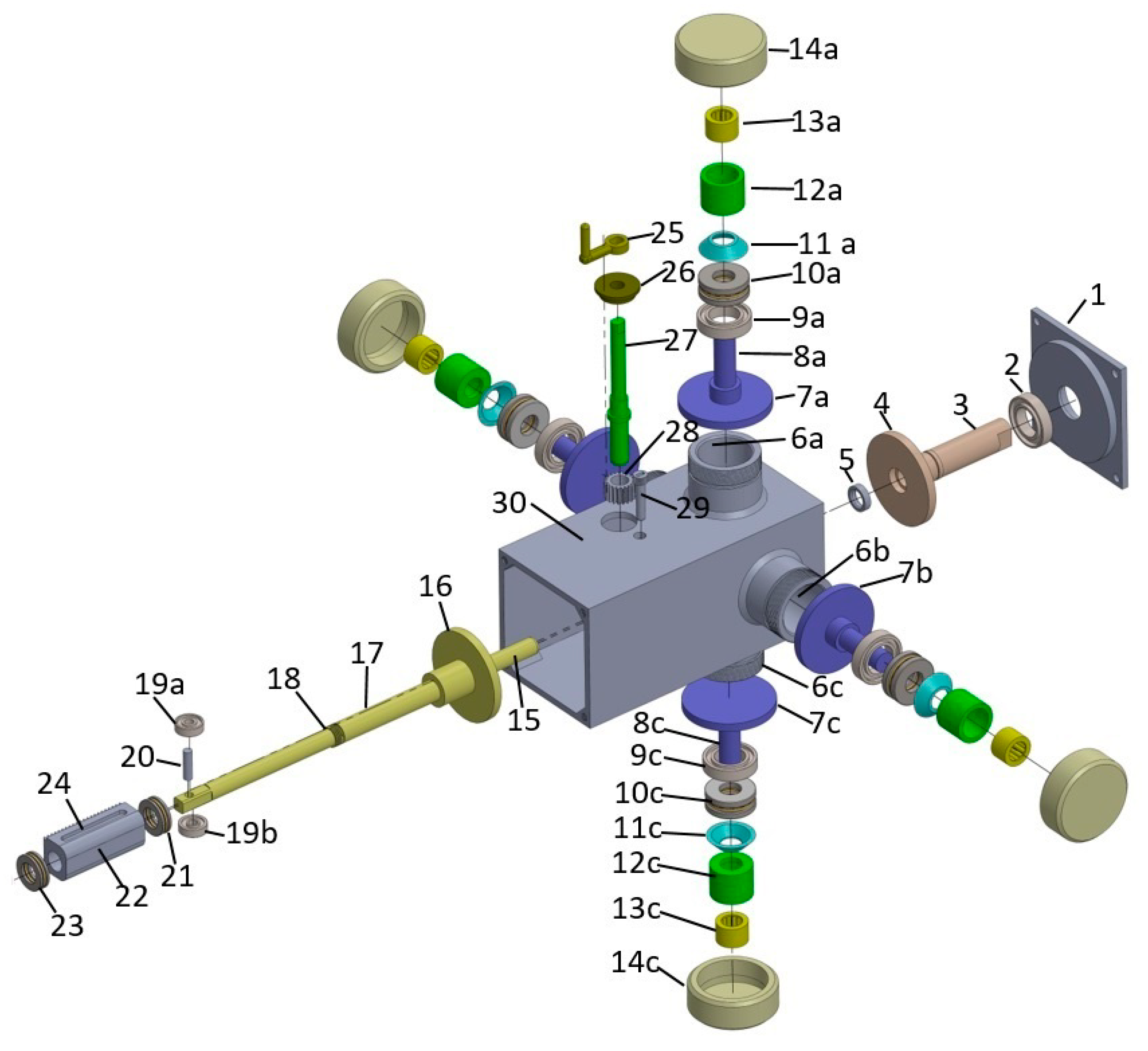






| S.No | Part No | Description |
|---|---|---|
| 1 | ‘1’ | Input side lid. |
| 2 | ‘2’ | Input shaft bearing. |
| 3 | ‘3’ | Input Shaft |
| 4 | ‘4’ | Input Disk |
| 5 | ‘5’ | The alignment bearing fitted in input shaft ‘3’ and alignment shaft ‘15’ axially moves in it. |
| 6 | ‘6a’, ‘6b’ ‘6c’, ‘6d’ | Housing for accommodating circumferentially arranged disks ‘7a’, ‘7b’, ‘7c’, ‘7d’, and miscellaneous components. |
| 7 | ‘7a’, ‘7b’, ‘7c’, ‘7d’ | Circumferentially arranged disks. They have traction contact with input disk ‘4’ and output disk ‘16’. The circumferentially arranged disks ‘7a’, ‘7b’, ‘7c’, and ‘7d’, along with input disk ‘4’ and output disk ‘16’, form the backbone of the proposed CVT design. |
| 8 | ‘8a’, ‘8b’, ‘8c’, ‘8d’ | Shafts of the circimferentially arranged disks ‘7a’, ‘7b’, ‘7c’, ‘7d’, respectively. |
| 9 | ‘9a’, ‘9b’, ‘9c’, ‘9d’ | Ball bearing for supporting one end of the shafts ‘8a’, ‘8b’, ‘8c’, ‘8d’, respectively. They keep the circumferentially arranged disks firmly in its place. Moreover it also helps in smooth rotary motion of the circumferentially arranged disks. |
| 10 | ‘10a’, ‘10b’, ‘10c’, ‘10d’ | Thrust bearing. They tranfer the axial load provided by bellivele spring (Disk spring) to the circumferentially arranged disks without hindering the rotary motion of the circumferentially arranged disks. |
| 11 | ‘11a’, ‘11b’, ‘11c’, ‘11d’ | Bellivelle springs/Disk springs. They provide a continuous axial loading to the circumferentially arranged disks. It is because of the axial loading provided by these springs that traction between cirmferentially arranged disks and input and output disk is produced. |
| 12 | ‘12a’, ‘12b’, ‘12c’, ‘12d’ | It is a sort of spacer which has two intended functions. Firstly it transferes axial load from Caps ‘14a’, ‘14b’, ‘14c’ and ‘14d’ to the respective disk springs. Secondly it acts as a housing for pin bearings ‘13a’, ‘13b’, ‘13c’, and ‘13d’. |
| 13 | ‘13a’, ‘13b’, ‘13c’, ‘13d’ | Pin bearing which support the outer ends of shafts ‘8a’, ‘8b’, ‘8c’ and ‘8d’. They help in keeping the circumferentially arranged disks in place and helps in their smooth rotation. |
| 14 | ‘14a’, ‘14b’, ‘14c’, ‘14d’ | Caps for CADs housing ‘6a’, ‘6b’, ‘6c’, ’6d’. it is also used for adjusting force applied on CADs. By tightening these caps we can increase the tractive force between CADs and input disk ‘4′ and output disk ‘16′. |
| 15 | ‘15’ | Alignment shaft. It is actually an extension of the output shaft. It can rotate and can also be moved axially inside the input shaft ‘3’ via bearing ‘5’. It keeps the input shaft ‘4’ and output shaft ‘17’ perfectly aligned. |
| 16 | ‘16’ | Output disk. it is connected to output shaft ‘17’ and has a traction contact with circumferentially arranged disks. It main purpose is to transfer motion from circumferentially arranged disks (CADs) to the output shaft. It is pertinent to mention that the location of its traction contact on the circumferentially arranged disks determines gear ratio. |
| 17 | ‘17’ | Output shaft. |
| 18 | ‘18’ | Threads on the output shaft for retaininh axial movement of the rack ‘22’. |
| 19 | ‘19a’, ‘19b’ | These are roller bearings attached to the outermost end of the shaft. The load to be driven by CVT will have a shaft which will be square in shape from inside and must be hollow so that these rolloer bearing can be axially moved inside the hollow shaft. During changing gear ratio when the output shaft will be moved axially, these bearings will help in reduction of friction between the output shaft of the CVT and input shaft of the load. |
| 20 | ‘20’ | Pin supporting bearing ‘19a’ and ‘19b’. |
| 21 | ‘21’ | Thrust bearing between rack ‘22’ and output shaft ‘17’. This reduces friction between rack ‘22’ and output shaft ‘17’ when the output shaft is axially pushed towards the input shaft during gear ratio change. |
| 22 | ‘22’ | Rack. It is part of the rack and pinion mechanism whose purpose is to move the output shaft in axial direction for gear ratio change. |
| 23 | ‘23’ | Thrust bearing between rack ‘22’ and output shaft ‘17’. This reduces friction between rack ‘22’ and output shaft ‘17’ when the output shaft is axially pushed away from the input shaft during gear ratio change. |
| 24 | ‘24’ | Guiding slot in the rack ‘22’. This restricts the movement of the rack to axial direction only. |
| 25 | ‘25’ | Handle for operating rack and pinion mechanism for gear ratio change. |
| 26 | ‘26’ | Bus h/Bearing. |
| 27 | ‘27’ | Pinion shaft. |
| 28 | ‘28’ | A small spur gear acting as a pinion. |
| 29 | ‘29’ | Guiding pin which sits in the guiding slot of the rack. |
| 30 | ‘30’ | CVT casing. |
| 31 | ‘31′ | Output Shaft Bearing. |
| S. No | Contact Length 2a (mm) | No of CADs n | Rotation Speed ωo (rad/sec) | Efficiency |
|---|---|---|---|---|
| 1 | 2 × 2.5 mm | 4 | 250 | 79% |
| 2 | 2 × 1 mm | 4 | 250 | 90.56% |
| 3 | 2 × 0.5 mm | 4 | 250 | 94.4% |
| S.No | Output Shaft Length. (mm) | Rdo (mm) | Rdin (mm) | Transmission Ratio. TR (As per Equation (14)) | Input shaft Rotatio (Degrees) | Output shaft Rotation. (Degrees) | Transmission Ratio. TR (Experimental) |
|---|---|---|---|---|---|---|---|
| 1 | 93 | −23 | 23 | −1 | 360 | −360 | −1 |
| 2 | 91 | −21 | 23 | −0.913 | 360 | −328 | −0.911 |
| 3 | 89 | −19 | 23 | −0.826 | 360 | −297 | −0.825 |
| 4 | 87 | −17 | 23 | −0.739 | 360 | −266 | −0.738 |
| 5 | 85 | −15 | 23 | −0.652 | 360 | −234 | −0.65 |
| 6 | 83 | −13 | 23 | −0.565 | 360 | −203 | −0.563 |
| 7 | 81 | −11 | 23 | −0.478 | 360 | −172 | −0.477 |
| 8 | 79 | −9 | 23 | −0.391 | 360 | −140 | −0.388 |
| 9 | 77 | −7 | 23 | −0.304 | 360 | −109 | −0.302 |
| 10 | 75 | −5 | 23 | −0.217 | 360 | −78 | −0.2166 |
| 11 | 73 | −3 | 23 | −0.130 | 360 | −46 | −0.127 |
| 12 | 71 | −1 | 23 | −0.043 | 360 | −15 | −0.041 |
| 13 | 69 | 1 | 23 | 0.043 | 360 | 15 | 0.041 |
| 14 | 67 | 3 | 23 | 0.130 | 360 | 47 | 0.13 |
| 15 | 65 | 5 | 23 | 0.217 | 360 | 78 | 0.216 |
| 16 | 63 | 7 | 23 | 0.304 | 360 | 110 | 0.3055 |
| 17 | 61 | 9 | 23 | 0.391 | 360 | 141 | 0.3916 |
| 18 | 59 | 11 | 23 | 0.478 | 360 | 172 | 0.477 |
| 19 | 57 | 13 | 23 | 0.565 | 360 | 204 | 0.566 |
| 20 | 55 | 15 | 23 | 0.652 | 360 | 234 | 0.65 |
| 21 | 53 | 17 | 23 | 0.739 | 360 | 266 | 0.7388 |
| 22 | 52 | 19 | 23 | 0.826 | 360 | 281 | 0.78 |
Disclaimer/Publisher’s Note: The statements, opinions and data contained in all publications are solely those of the individual author(s) and contributor(s) and not of MDPI and/or the editor(s). MDPI and/or the editor(s) disclaim responsibility for any injury to people or property resulting from any ideas, methods, instructions or products referred to in the content. |
© 2024 by the authors. Licensee MDPI, Basel, Switzerland. This article is an open access article distributed under the terms and conditions of the Creative Commons Attribution (CC BY) license (https://creativecommons.org/licenses/by/4.0/).
Share and Cite
Bilal, M.; Zhu, Q.; Qureshi, S.R.; Elahi, A.; Nadeem, M.K.; Khan, S. A Novel Continuously Variable Transmission with Circumferentially Arranged Disks (CAD CVT). Actuators 2024, 13, 208. https://doi.org/10.3390/act13060208
Bilal M, Zhu Q, Qureshi SR, Elahi A, Nadeem MK, Khan S. A Novel Continuously Variable Transmission with Circumferentially Arranged Disks (CAD CVT). Actuators. 2024; 13(6):208. https://doi.org/10.3390/act13060208
Chicago/Turabian StyleBilal, Muhammad, Qidan Zhu, Shafiq R. Qureshi, Ahsan Elahi, Muhammad Kashif Nadeem, and Sartaj Khan. 2024. "A Novel Continuously Variable Transmission with Circumferentially Arranged Disks (CAD CVT)" Actuators 13, no. 6: 208. https://doi.org/10.3390/act13060208
APA StyleBilal, M., Zhu, Q., Qureshi, S. R., Elahi, A., Nadeem, M. K., & Khan, S. (2024). A Novel Continuously Variable Transmission with Circumferentially Arranged Disks (CAD CVT). Actuators, 13(6), 208. https://doi.org/10.3390/act13060208


