Abstract
This study describes the activity of developing a force amplifier exoskeleton with one degree of freedom. The system was developed as a research prototype to conduct control system studies. The device consists of an arm with a pneumatic cylinder actuator controlled by a pressure regulator. As for the human–machine interface, the system has a force sensor. The idea is to verify the possibility of developing a simple system from the sensor system’s point of view and the control system’s architecture while simultaneously obtaining an effective, economical, and reliable device. The idea developed in this project is to use the user’s available ability to control movements in unknown environments. The user constitutes the central part of the entire control system: he defines the references for the speeds and forces to be applied to the environment and observes the rates of the controlled robotic system through his own sight and proprioceptive system. On the other hand, the machine produces and controls the forces applied to the environment by the actuator. In this way, the device shows an increased admittance. A mathematical system model was created to verify the idea’s feasibility. Following the results of the simulations, a prototype was built on which experimental tests were carried out. As stated above, it was possible to obtain the described behavior with the use of a force sensor, one-axis type, interposed between the machine and the user, to constitute the human–machine interface; using a pressure regulator, it was possible to avoid the sensors for the force feedback by the environment. The result is a simple architecture for the sensors and the control algorithm. Specific test protocols were proposed to test the performance of the human–machine “system”, and a test bench was developed that allows the tracking of variable signals represented on a monitor, which the user must follow. The system is intuitive to use, with a rapid learning curve, and the user can handle high loads according to the different signals to be followed with good precision, even at high speeds.
1. Introduction
In many areas of human life, it is required to move loads. In the industrial production sector, human strength is often insufficient to move components or assembled items during the assembly stages. Thinking also about other fields, it is evident that the need to carry loads is a widespread task: for example, in agricultural or food production, civil construction or activities in goods’ warehouses, and, additionally, in the biomedical field, there is the problem of assisting the sick and infirm. Patients need to be placed in a sitting position on the bed or, for example, in a wheelchair. The task of moving loads is often complicated by the need to carry out the movement with precision. When it is not required to follow a precise trajectory in space, it may be necessary to position the object on a specific point and with a given orientation. This task is particularly difficult for humans, who can only be accurate with small loads while the accuracy is reduced under stress. On the scientific research front, robotic devices capable of amplifying human strength have been studied for several years and have been proposed either as rehabilitation systems [1,2,3,4,5,6], or as aids [7,8,9,10,11,12], or precisely as the amplifiers of non-disabled people’s strength [13,14,15]. Amplifying human force means the machine can permit the person to always feel the same (however variable) fraction of the external load. From the architectural point of view, these systems can be of various types when contemplating the anthropomorphic arm structure but can experience considerable evolutions up to the possibility of being worn by the operator to constitute real-force-amplifier exoskeletons, soft suite machines, or exoskeleton machines with rigid segments or with elastic elements. The type of actuator can also be a distinctive element: devices with electric [16,17,18,19,20,21,22], hydraulic [23,24,25,26], or pneumatic actuators [27,28,29,30,31,32,33,34] have been proposed. An essential part of the research was also recently dedicated to passive systems [35,36,37,38] that are intrinsically safer, from the point of view of possible malfunctions, but which do not perform as well as the active ones. Interacting with the external environment is an essential aspect of controlling these devices [39,40,41,42,43]. In movements interacting with the environment, the interaction forces must be supported rather than opposed. Lately, the study of human–machine interaction within the Industry 4.0 ecosystem with collaborative robots has received much attention in research. Historically, regarding the human–machine interface, two approaches have been proposed to solve this problem. The first approach controls strength and position without conflict [44,45]. With this approach, the forces are held in contrast to the environmental constraints, while the movements are implemented along the directions in which the manipulator is free to move. The second approach aims to define links between interaction forces and movement [46,47,48,49]. The first approach can be seen as a particular case of the second, which is more efficient than the first and allows manipulations in unknown environments while keeping the forces of interaction with the environment under control. A typical control case operating with this approach is that of impedance control. With this approach, monitoring the interaction force and movement trend is necessary. Therefore, the device is rather complex from the point of view of the control system. This study aims to develop a simple handling system from the point of view of the hardware and control software, exploiting the user’s available skills in manipulating loads that interact with the external environment. A prototype was created to verify the design choices; therefore, the device has kinematics limited to a single motorized degree of freedom. The device looks like an anthropomorphic arm suspended from a frame resting on a base on the ground. With reference to Figure 1, the device has an arm hinged to the shoulder, and a pneumatic cylinder with a 50 mm bore was chosen to carry out the movement.
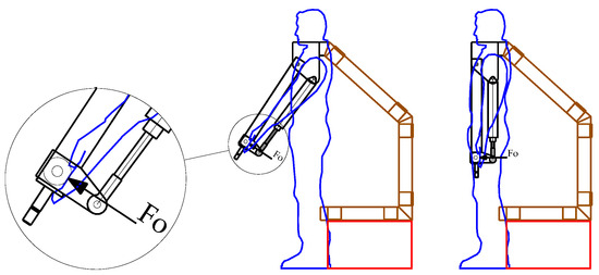
Figure 1.
The device developed has an anthropomorphic structure (black) suspended from a frame (brown) on a ground base (red). The human exchanges with the machine an interaction force FO.
For the realization of the force amplification function, it is necessary that the device can detect the operator’s intention and satisfy his will by providing strength in the movements. Usually, thinking in terms of robotic technology involves equipping the system with some sensor to detect the user’s intention and, during operation, using the signal provided by the sensor to establish, according to a specific algorithm, the level of force the machine must exercise on the outside instant by instant. It is also necessary to equip the system with other force sensors to detect the force applied to the environment to control any feedback actions to ensure the desired operation. This type of architecture is rather complex, especially concerning the control of the force applied by the device. For the device developed and presented in this paper, the problem was solved thanks to a proportional pressure valve. This valve, being equipped internally with a feedback system, can receive a signal and ensure the pressure inside the actuator and, therefore, a force on the machine that is proportional to the input signal; this way, there is no need for additional sensors and control software to verify the application of the correct force value moment by moment. In this way, the device is elementary regarding hardware and software. In addition to the use of the valve, it needs only a force sensor for detecting the user’s intention and a small microcontroller that implements the algorithm software, which is very simple: it calculates the signal value to be sent to the proportional regulator which depends on the parameters of the physical system (masses and kinematics, actuator), on the parameters of the force sensor, and, finally, on the level of amplification of the force to be obtained.
During operation, the user must guide the load in the desired direction. The machine senses the operator’s intention and provides a force in the right direction so that the operator always feels the same fraction of the load. That is, if the amplification level is adjusted to have a factor of 10, if a load of 500 N has to be moved, the operator feels a load of 50 N while, for example, if the load to be handled is 300 N, the operator senses a load of 30 N.
2. Materials and Methods
2.1. Modeling
Before proceeding with the construction of the prototype in question, the system was modeled to verify the validity of the design choices, especially regarding the architecture of the control system based on the proportional valve. To this end, modeling of the entire system was carried out. In particular, a fluid dynamic model of the airflow inside the pneumatic cylinder, a model of the proportional valve [50,51,52], and a model of the mechanical system structure were considered. The equations of the three models considered referring to the schemes shown in Figure 2 are shown below with symbols.
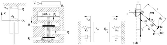
Figure 2.
Diagram of the cylinder, proportional valve, and arm.
As for the actuator, it is a FESTO DCN-50-625-P pneumatic cylinder. The proportional valve is the SMC-VY1200, with the following features: Pressure range 0.005–0.88 MPa, supply voltage 24 V, input signal 0–5 V.
The three models were considered together to form a single model in the Simulink environment to proceed with the project’s feasibility checks. Considering the symbols in Figure 2, the pressure value in the posterior chamber is obtained by integrating the following expression:
where is the volume flow, k is the ratio of specific heat equal to 1.4, R is the gas constant for air equal to 287 J kg−1 K−1, and Ts is the reference temperature equal to 300 K.
The volume flow that the pressure proportional valve supplies to the cylinder takes the following expression:
with cq valve discharge coefficient equal to 0.9, ks obturator circumference equal to 3 × 10⁻² m, cmp1 and cmp2 inlet and outlet flow coefficients, Ps supply pressure and with:
The and are mutually exclusive, i.e., if one is different from zero, the other is equal to zero. This is because the spool is in contact with only one shutter at a time. This means the actuator, at a given time, is connected with the supply or the exhaust except when both shutters are closed. The same is true for the forces acting on the shutters, and ; they have the expression:
Furthermore:
Pd = (Vi − 1) kv + Pr (pilot pressure with Pr reference pressure equal to 100,000 Pa).
The rotation balance for the arm is as follows:
As for the control algorithm, as previously introduced, this is very simple, and, considering the controller as a black box, the transfer function is to generate, for the control valve, a signal proportional to the input signal generated by the human–machine interface force sensor. The relationship implemented in the computer that links the voltage generated by the load cell to the voltage Vi is the following:
with gain constant , load cell output voltage Vc, load cell calibration constant kc equal to 0.01 V/N, valve constant kv equal to 2.3 × 10⁵ Pa/V; while the signal provided by the load cell that measures the force exerted by the operator can be written as follows:
where is the reference rotation desired by the operator, is the rotation achieved by the system, Fo is the force applied by the user, kd is the elastic constant of the upper limb estimated at 5000 N/m.
All the above relationships were implemented together in a numerical model inside MATLAB/Simulink, the general scheme of which is presented in Figure 3.
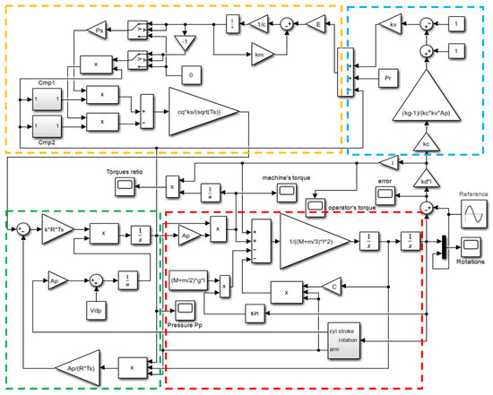
Figure 3.
Principal simulation scheme of the modeled system. The load cell model is in the blue box; the pressure regulator and the air system models are in the orange box. In the green box, there is the cylinder model, and in the red box, there is the mechanical system model.
Once the modeling phase was completed, it was possible to carry out various simulations. This phase aimed to verify whether the idea behind the device, the operation as a force amplifier, could work and if the goal was achievable through a proportional pressure regulator. It was, therefore, a question of verifying, once a time-varying movement had been imposed on the model, first of all, whether the device faithfully followed the desired action without incurring instability phenomena; second, that the system provided the correct level of movement assistance force. The verification was largely positive on all types of imposed movements.
For example, Figure 4a shows the result of a simulation in which a sinusoidal movement was used as input to the device compared to the movement performed by the device. As can be seen, the tracking ability is remarkable. The pressure value inside the pneumatic cylinder for the same test is on the right.
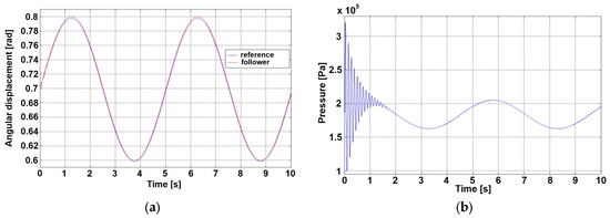
Figure 4.
Numerical simulation: trajectory tracking (a), pressure inside the pneumatic cylinder (b).
2.2. Device Design and Realization
After the positive checks on the numerical model, the executive design of the device and its construction proceeded. Figure 5, on the left, shows a 3D CAD drawing of the developed device. The force sensor is placed near the end effector, where it is natural for the operator to put his hand. This AEP transducer load cell has a full scale of 1000 N and a 2 mV/V bridge sensitivity. Support for weights was provided as the end-effector of the machine to carry out experimental tests with different masses to be handled. Subsequently, the force amplifier device was made. Figure 5 shows a CAD model of the device, a picture of the realized prototype, and a control system scheme. Figure 6a shows a view of the device during operation with an operator. An experimental characterization campaign of the device was carried out to verify its proper functioning.
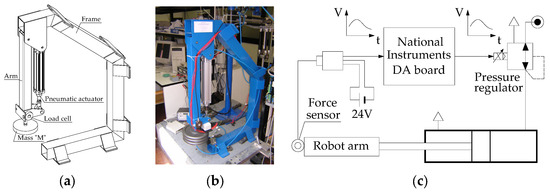
Figure 5.
Design of the device (a), realized prototype (b), and scheme of the control system (c).
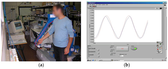
Figure 6.
The device during operation (a); comparison between the reference signal (in red) and the trajectory signal carried out by the human–machine system (in blue) relating to a test carried out (b).
In this case, despite involving a robotic device, the standard characterization tests, such as the step and the ramp responses, cannot highlight all the aspects of interest; the device works in close relationships with humans.
Some performance parameters to be observed have been identified to characterize the human–machine system. A device of this type performs better the more it is able (1) to allow the handling of high loads, (2) to carry out agile movements, i.e., in which sudden changes in direction of movement or accelerations are required, (3) to perform the task with precision, that is, following a given trajectory in space. To observe these three performance indices, experimental tests were designed in which the operator moved loads having in front of him a monitor in which the actual position of the device was represented on a graph, in real time, together with a position reference to be chased that was dynamically shown over time. The references were sinusoidal signals of a given amplitude and frequency and a discontinuous random signal as a series of steps in both directions and of variable amplitudes. An experimental setup was set up by which, with various tests varying the load to be handled and, independently, the characteristics of the signal to be tracked, it was possible to verify the precision with which different operators carried out the handling. Figure 6b shows, for an example test, the comparison between the reference signal to be followed and the trajectory made. The ability to follow the given trajectory is evident.
Experimental tests were conducted with six different individuals, three male and three female, to better evaluate the ability of each to interact with the device, varying the mass of the payload, the gain constant (which binds the load supported by the machine to that supported by the operator), and the reference trends to be followed.
The following conditions were analyzed:
- a mass M relating to the payload with values equal to 0–10 kg;
- a gain constant Kg that adjusts the control algorithm with values equal to 30–45;
- reference signals of the type:
- ○
- sinusoidal, considering:
- ▪
- an amplitude of oscillation A with values equal to 15–30 degrees;
- ▪
- an average value of the Vm oscillation with values equal to 40 degrees;
- ▪
- an oscillation frequency f with values equal to 0.1–0.2 Hz;
- ○
- random variable (slow): the desired position is updated every 4 s.
As for the random signal, a signal was used that assumes predefined values relating to the rotation range of the arm (about 90°) and remains constant for 4 s. To compare the results obtained, the random signal was the same for all individuals.
3. Results
During the tests, the following were acquired: (1) the trends of the reference and the actual one of the rotation of the arm to calculate the error; (2) the voltage signals relating to the load cell, which measures the force by the operator, and to the pressure transducer, which measures the pressure in the cylinder related to the force exerted by the machine.
During the postprocessing of the data, the following were determined: (1) the normalized average operator torque Ru, calculated as the average of the ratios between the torque exerted by the operator and the sum of the operator torque and machine torque, the normalized average machine torque Rm, calculated as the average of the ratios between the torque exerted by the machine and the sum of the operator and machine torque; (2) as for the sinusoidal signal, the average error emid, calculated as the average of the absolute values relating to the difference between the sinusoidal trend to be followed and the actual rotation of the prototype arm, the maximum error emax, as a maximum of such absolute values; (3) as for the random signal, the normalized error Ierr, calculated as the sum of the absolute values relating to the difference between the signal to be followed and the actual signal of the arm divided by the sum of the absolute values of the signal to be followed, the average positioning time tmidp, calculated as the average of the times necessary for the operator to cope with the variations in the signal between one constant value and the next, the average positioning error emidp, calculated as the average of the absolute values relating to the difference between the random trend to be followed and the actual one of the arm after positioning.
As for the sinusoidal signal, considering for each test and each individual an acquisition time of 40 s, the values of emid, emax, Ru, and Rm were calculated over a time of 30 s, between 10 and 40 s, omitting the first 10 s necessary for the operator to adapt to the monitored signal, the presence or absence of the load to be lifted, and the variation of the constant Kg.
As for the random signal, the values of Ierr, tmidp, emidp, Ru, and Rm were calculated over an acquisition time of 60 s.
In Table 1, Table 2, Table 3 and Table 4, the results of the experimental plan presented above are shown.

Table 1.
Results of the tests with a load of M = 10 kg, gain Kg = 30.
Table 2.
Results of the tests with a load of M = 10 kg, gain Kg = 45.
Table 3.
Results of the tests with a load of M = 0 kg, gain Kg = 30.
Table 4.
Results of the tests with a load of M = 0 kg, gain Kg = 45.
From the analysis of the results, increasing the gain constant Kg from 30 to 45, i.e., increasing it by 15 units, it is observed that:
- Ru decreases by 30.8%, while Rm increases by 4.6%, for tests with sinusoidal reference signal amplitude of 30°;
- Ru decreases by 28.6%, while Rm increases by 4.65% for the tests with a reference sinusoidal signal amplitude of 60° and the random tests.
Moving on from the tests without applied load to those with load M = 10 kg, it is noted that:
- Ru decreases by 13.3%, while Rm increases by 2.35%, for tests with sinusoidal reference signal amplitude of 30° and gain constant of 30;
- Ru decreases by 18.2%, while Rm increases by 2.5%, for tests with sinusoidal reference signal amplitude of 30° and gain constant 45;
- Ru decreases by 12.5%, while Rm increases by 2.4%, for tests with gain constant 30 relating to the sinusoidal reference of 60° amplitude and the random signal;
- Ru decreases by 16.7%, while Rm increases by 2.3%, for the tests with gain constant 45 relative to the sinusoidal reference of 60° amplitude and to the random signal.
By decreasing the amplitude of oscillation of the sinusoidal signal from 30° to 15°, it is noted that:
- Ru decreases by 7.1%, while Rm increases by 1.2% for tests with a load of 30 kg and a gain constant of 30;
- Ru decreases by 10%, while Rm increases by 1.1% for tests with a load of 30 kg and a gain constant of 45;
- Ru decreases by 6.25%, while Rm increases by 2.4%, for the tests without applied load and gain constant 30;
- Ru decreases by 15.4%, while Rm increases by 2.3%, for the tests without applied load and gain constant 45.
Ru and Rm have no variations as the oscillation frequency f varies for tests with sinusoidal signals.
As for the analysis of the average emid error relative to the sinusoidal reference, on average, as the parameters considered and based on the different subjects vary, there are an emid error of about 1.8° relative to movements with an amplitude equal to 30° and an emid error of approximately 3.2° relative to movements of 60° amplitude.
As for the analysis of the maximum error emax relative to the sinusoidal reference, on average, as the parameters considered and based on the different subjects vary, there are an emax error of about 5.9° relative to movements with an amplitude equal to 30° and an emax error of approximately 10.5° relative to movements with an amplitude equal to 60°.
On average, it is found that there are:
- an increase in emax of about 24% by increasing the applied load M from 0 kg to 10 kg;
- a reduction in emax of about 6.3% by increasing the gain constant from 30 to 45;
- an increase in emax of about 76% by increasing the amplitude A from 15° to 30°;
- an increase in emax of about 43.5% by increasing the frequency f from 0.1 Hz to 0.2 Hz.
As for the analysis of the tests with a random reference signal, on average, as the parameters considered vary and based on the different subjects, there are a normalized error Ierr of about 0.21 from 0.175 ÷ 0.259, a positioning time tmidp of approximately 2.7 s from 2.2 s ÷ 3.3 s, and an error after positioning and emidp of about 0.6° from 0.3° ÷ 1.2° relative to a signal consisting of a sequence of steps of variable amplitude between 10° and 70° with an average value of about 31°.
4. Discussion
Below are some graphs relating to a test in which the following parameters were considered:
- mass relative to the payload M = 0 kg;
- gain constant Kg = 30;
- individual 5;
- amplitude of sinusoidal signal oscillation A = 30° (average value of 40°);
- sinusoidal signal oscillation frequency f = 0.1 Hz.
In Figure 7a, it can be seen how the individual follows the imposed reference very well: the rotation error between the reference and the configuration reached is shown with an average value emid equal to 1.212° and a maximum value emax equal to 3.294° on an amplitude of movement of 60°, having considered the data relating to the interval of 10 ÷ 40 s.
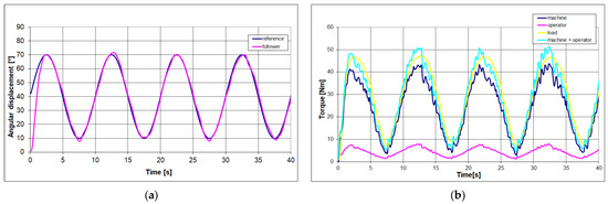
Figure 7.
Comparison between the “chased” and “chasing” trends relating to the rotation of the arm (a); trends concerning the torques of the machine, operator, load, and human–machine (b).
Figure 7b shows the trends relating to the torque exerted by the machine, the torque exerted by the human, the torque relating to the payload, and the resulting torque between the machine torque and the operator torque, having considered the data relating to the interval of 10 ÷ 40 s.
Furthermore, Ru, i.e., the action exerted by the operator compared to the resulting human–machine, is equal on average to 16%, while Rm, i.e., the action exerted by the machine with respect to the resultant human–machine, is equal on average to 84%.
Below are some graphs relating to the “3-10-sr-45” test, in which the following parameters were considered:
- mass relative to the payload M = 10 kg;
- gain constant Kg = 45;
- individuals 3;
- random signal.
In Figure 8a, it can be seen how the user follows the imposed reference quite well; there is an average rotation error emidp after positioning equal to 0.536°, relating to a signal consisting of a sequence of steps of variable amplitude between 10° and 70° with an average value of approximately 31°, and an average positioning time tmidp, relating to the transient necessary for the operator to cope with the variation between one constant value and the next, equal to 2.613 s.
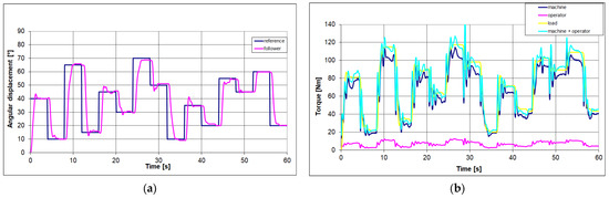
Figure 8.
Comparison between the “chased” and “chasing” trends relating to the rotation of the arm (a); trends concerning the torques of the machine, operator, load, and human–machine (b).
Figure 8b shows the trends relating to the torque exerted by the machine, the torque exerted by the human, the torque relating to the payload, and the resulting torque between the machine torque and the operator torque. Furthermore, Ru, i.e., the action exerted by the user with respect to the resultant human–machine, is equal on average to 10%, while Rm, i.e., the action exerted by the device with respect to the resulting human–machine, is equal on average to 90%.
The results conclude that it is possible to realize a force amplifier system with simple hardware architecture and that it can be very efficient since the possibility of handling large loads in an agile and precise way has been demonstrated. The results encourage the investigation of a kinematically more complex system to support movements with more degrees of freedom.
5. Conclusions
The experimental results highlight that the human–machine system handles high loads with acceptable precision and agility. The load, worth 10 kg, was moved according to sinusoidal signals, completing complete cycles in 5 s and 10 s, with amplitudes of the order of magnitude of 60° with errors of 6%. The tests with random signals also provided satisfactory results, with positioning times in the range of 3 s and positioning errors of the order of 2% on signal variations of about 30°.
The first impression when working with the device is that it is immediately usable without training. The operator has to act intuitively and can move the load naturally, having total control over it. Furthermore, during movement, the operator can maintain sensitivity to the environment, which helps improve the accuracy of the action.
There is no risk of encountering and damaging an obstacle, as possible with a device without force feedback from the environment. For example, an operator is able, in a confrontation of strength with three to four people at the same time, to easily prevail over them without ever causing any danger, given the great sensitivity to the environment that the system guarantees to the operator. This suggests the possibility of quickly handling high and fragile loads.
Author Contributions
Conceptualization, F.D.; methodology, F.D., P.B.Z. and T.R.; validation, F.D.; formal analysis, F.D., P.B.Z. and T.R.; investigation, F.D., P.B.Z. and T.R.; data curation, F.D.; writing—original draft preparation, F.D.; writing—review and editing, F.D.; visualization, F.D., P.B.Z. and T.R.; supervision, F.D., P.B.Z. and T.R. All authors have read and agreed to the published version of the manuscript.
Funding
This research received no external funding.
Informed Consent Statement
Informed consent was obtained from all subjects involved in the study.
Data Availability Statement
Data are contained within the article.
Acknowledgments
The authors would like to acknowledge the support given by Luca Auriti for the contribution provided to the experimental activity.
Conflicts of Interest
The authors declare no conflict of interest.
References
- Rosen, J.; Brand, M.; Fuchs, M.; Arcan, M. A myosignal-based powered exoskeleton system. IEEE Trans. Syst. Man Cybern.-Part A Syst. Hum. 2001, 31, 210–222. [Google Scholar] [CrossRef]
- Durante, F.; Raparelli, T.; Beomonte Zobel, P. Two-Dof Upper Limb Rehabilitation Robot Driven by Straight Fibers Pneumatic Muscles. Bioengineering 2022, 9, 377. [Google Scholar] [CrossRef] [PubMed]
- Sacco, K.; Belforte, G.; Eula, G.; Raparelli, T.; Sirolli, S.; Geda, E.; Geminiani, G.C.; Virgilio, R.; Zettin, M. P.I.G.R.O.: An active exoskeleton for robotic neurorehabilitation training driven by an electro-pneumatic control. Mech. Mach. Sci. 2018, 49, 845–853. [Google Scholar] [CrossRef]
- Koceska, N.; Koceski, S.; Durante, F.; Zobel, P.B.; Raparelli, T. Control architecture of a 10 DOF lower limbs exoskeleton for gait Rehabilitation. Int. J. Adv. Robot. Syst. 2013, 10, 68. [Google Scholar] [CrossRef]
- Kawasaki, H.; Ito, S.; Ishigure, Y.; Nishimoto, Y.; Aoki, T.; Mouri, T.; Sakaeda, H.; Abe, M. Development of a Hand Motion Assist Robot for Rehabilitation Therapy by Patient Self-Motion Control. In Proceedings of the IEEE 10th International Conference on Rehabilitation Robotics (ICORR), Noordwijk, The Netherlands, 13–15 June 2007; pp. 234–240. [Google Scholar]
- Mayr, A.; Kofler, M.; Saltuari, L. ARMOR: An electromechanical robot for upper limb training following stroke. A prospective randomised controlled pilot study. Handchir. Mikrochir. Plast. Chir. 2008, 40, 66–73. [Google Scholar] [CrossRef]
- Kiguchi, K.; Iwami, K.; Yasuda, M.; Watanabe, K.; Fukuda, T. An exoskeletal robot for human shoulder joint motion assist. IEEE/ASME Trans. Mechatron. 2003, 8, 125–135. [Google Scholar] [CrossRef]
- Durante, F.; Raparelli, T.; Zobel, P.B. Development of a 4-DoF Active Upper Limb Orthosis. Robotics 2022, 11, 122. [Google Scholar] [CrossRef]
- Cozens, J.A. Robotic assistance of an active upper limb exercise in neurologically impaired patients. IEEE Trans. Rehabil. Eng. 1999, 7, 254–256. [Google Scholar] [CrossRef]
- Ögce, F.; Özyalçin, H. Case study: A myoelectrically controlled shoulder-elbow orthosis for unrecovered brachial plexus injury. Prosthet. Orthot. Int. 2000, 24, 252–255. [Google Scholar] [CrossRef]
- Cordo, P.; Lutsep, H.; Cordo, L.; Wright, W.G.; Cacciatore, T.; Skoss, R. Assisted movement with enhanced sensation (AMES): Coupling motor and sensory to remediatemotor deficits in chronic stroke Patients. Neurorehabilit. Neural Repair 2009, 23, 67–77. [Google Scholar] [CrossRef]
- Durante, F.; Zobel, P.B.; Raparelli, T. Development of an active orthosis for inferior limb with light structure. Mech. Mach. Sci. 2018, 49, 833–841. [Google Scholar] [CrossRef]
- Kazerooni, H.; Guo, J. Human Extenders. J. Dyn. Syst. Meas. Control 1993, 115, 281–290. [Google Scholar] [CrossRef]
- Kazerooni, H.; Mahoney, S.L. Dynamics and control of Robotic Systems Worn by Humans. J. Dyn. Syst. Meas. Control 1991, 113, 379–387. [Google Scholar] [CrossRef] [PubMed]
- Kazerooni, H.; Steger, R. The Berkeley Lower Extremity Exoskeleton. J. Dyn. Syst. Meas. Control 2006, 128, 14–25. [Google Scholar] [CrossRef]
- Amirabdollahian, F.; Loureiro, R.; Gradwell, E.; Collin, C.; Harwin, W.; Johnson, G. Multivariate analysis of the Fugl-Meyer outcome measures assessing the effectiveness of GENTLE/S robot-mediated stroke therapy. J. Neuroeng. Rehabil. 2007, 4, 4. [Google Scholar] [CrossRef] [PubMed]
- Cheng, H.S.; Ju, M.S.; Lin, C.C.K. Improving elbow torque output of stroke patients with assistive torque controlled by EMG signals. J. Biomech. Eng. 2003, 125, 881–886. [Google Scholar] [CrossRef] [PubMed]
- Turner, M.; Gomez, D.; Tremblay, M.; Cutkosky, M. Preliminary tests of an arm-grounded haptic feedback device in telemanipulation. In Proceedings of the ASME Dynamic Systems and Control Division, Anaheim, CA, USA, 15–20 November 1998; Volume 64, pp. 145–149. [Google Scholar]
- Mali, U.; Munih, M. HIFE-haptic interface for finger exercise. Mechatron. IEEE/ASME Trans. 2006, 11, 93–102. [Google Scholar] [CrossRef]
- Hesse, S.; Kuhlmann, H.; Wilk, J.; Tomelleri, C.; Kirker, S.G.B. A new electromechanical trainer for sensorimotor rehabilitation of paralysed fingers: A case series in chronic and acute stroke patients. J. Neuroeng. Rehabil. 2008, 5, 21. [Google Scholar] [CrossRef]
- Burgar, C.G.; Lum, P.S.; Shor, P.C.; Van der Loos, H.F.M. Development of robots for rehabilitation therapy: The Palo Alto VA/Stanford experience. J. Rehabil. Res. Dev. 2000, 37, 663–673. [Google Scholar]
- Perry, J.C.; Rosen, J.; Burns, S. Upper-limb powered exoskeleton design. IEEE/ASME Trans. Mechatron. 2007, 12, 408–417. [Google Scholar] [CrossRef]
- Stienen, A.; Hekman, E.; Prange, G.; Jannink, M.; Aalsma, A.; van der Helm, F.; van der Kooij, H. Dampace. Design of an exoskeleton for force-coordination training in upper-extremity rehabilitation. J. Med. Devices 2009, 3, 10. [Google Scholar] [CrossRef]
- Pylatiuk, C.; Kargov, A.; Gaiser, I.; Werner, T.; Schulz, S.; Bretthauer, G. Design of a flexible fluidic actuation system for a hybrid elbow orthosis. In Proceedings of the IEEE International Conference on Rehabilitation Robotics (ICORR), Kyoto, Japan, 23–26 June 2009; pp. 167–171. [Google Scholar]
- Umemura, A.; Saito, Y.; Fujisaki, K. A study on power-assisted rehabilitation robot arms operated by patient with upper limb disabilities. In Proceedings of the IEEE International Conference on Rehabilitation Robotics (ICORR), Kyoto, Japan, 23–26 June 2009; pp. 451–456. [Google Scholar]
- Stienen, A.H.A.; Hekman, E.E.G.; ter Braak, H.; Aalsma, A.M.M.; van der Helm, F.C.T.; van der Kooij, H. Design of a rotational hydro-elastic actuator for an active upper-extremity rehabilitation exoskeleton. In Proceedings of the 2nd IEEE RAS & EMBS International Conference on Biomedical Robotics and Biomechatronics (BioRob), Scottsdale, AZ, USA, 19–22 October 2008; pp. 881–888. [Google Scholar]
- Durante, F.; Antonelli, M.G.; Zobel, P.B. Development of an active exoskeleton for assisting back movements in lifting weights. Int. J. Mech. Eng. Robot. Res. 2018, 7, 353–360. [Google Scholar] [CrossRef]
- Takahashi, C.D.; Der-Yeghiaian, L.; Le, V.; Motiwala, R.R.; Cramer, S.C. Robot-based handmotor therapy after stroke. Brain 2008, 131 Pt 2, 425–437. [Google Scholar] [CrossRef] [PubMed]
- Sasaki, D.; Noritsugu, T.; Takaiwa, M. Development of Active Support Splint driven by Pneumatic Soft Actuator (ASSIST). In Proceedings of the IEEE International Conference on Robotics and Automation (ICRA), Barcelona, Spain, 18–22 April 2005; pp. 520–525. [Google Scholar]
- Kline, T.; Kamper, D.; Schmit, B. Control system for pneumatically controlled glove to assist in grasp activities. In Proceedings of the 9th International Conference on Rehabilitation Robotics ICORR, Chicago, IL, USA, 28 June–1 July 2005; pp. 78–81. [Google Scholar]
- Klein, J.; Spencer, S.; Allington, J.; Bobrow, J.E.; Reinkensmeyer, D.J. Optimization of a parallel shouldermechanism to achieve a high-force, low-mass, robotic-arm exoskeleton. IEEE Trans. Robot. 2010, 26, 710–715. [Google Scholar] [CrossRef]
- Lucas, L.; Di Cicco, M.; Matsuoka, Y. An EMG-controlled hand exoskeleton for natural pinching. J. Robot. Mechatron. 2004, 16, 482–488. [Google Scholar] [CrossRef]
- Bouzit, M.; Burdea, G.; Popescu, G.; Boian, R. The Rutgers Master II-new design force-feedback glove. IEEE/ASME Trans. Mechatron. 2002, 7, 256–263. [Google Scholar] [CrossRef]
- Koceska, N.; Koceski, S.; Zobel, P.B.; Durante, F. Control architecture for a lower limbs rehabilitation robot system. In Proceedings of the 2008 IEEE International Conference on Robotics and Biomimetics, ROBIO 2008, Bangkok, Thailand, 22–25 February 2009; pp. 971–976. [Google Scholar] [CrossRef]
- Paterna, M.; Magnetti Gisolo, S.; De Benedictis, C.; Muscolo, G.G.; Ferraresi, C. A passive upper-limb exoskeleton for industrial application based on pneumatic artificial muscles. Mech. Sci. 2022, 13, 387–398. [Google Scholar] [CrossRef]
- Ashta, G.; Finco, S.; Battini, D.; Persona, A. Passive Exoskeletons to EnhanceWorkforce Sustainability: Literature Review and Future Research Agenda. Sustainability 2023, 15, 7339. [Google Scholar] [CrossRef]
- Öçal, A.E.; Lekesiz, H.; Çetin, S.T. The Development of an Innovative Occupational Passive Upper Extremity Exoskeleton and an Investigation of Its Effects on Muscles. Appl. Sci. 2023, 13, 6763. [Google Scholar] [CrossRef]
- Bennett, S.T.; Han, W.; Mahmud, D.; Adamczyk, P.G.; Dai, F.; Wehner, M.; Veeramani, D.; Zhu, Z. Usability and Biomechanical Testing of Passive Exoskeletons for ConstructionWorkers: A Field-Based Pilot Study. Buildings 2023, 13, 822. [Google Scholar] [CrossRef]
- Pacheco Quiñones, D.; Paterna, M.; De Benedictis, C.; Maffiodo, D.; Franco, W.; Ferraresi, C. Contact force regulation in physical human-machine interaction based on model predictive control. Robotica 2023, 41, 3409–3425. [Google Scholar] [CrossRef]
- Nadeau, N.A.; Bonev, I.A.; Joubair, A. Impedance Control Self-Calibration of a Collaborative Robot Using Kinematic Coupling. Robotics 2019, 8, 33. [Google Scholar] [CrossRef]
- Kim, H.; Yang, W. Variable Admittance Control Based on Human–Robot Collaboration Observer Using Frequency Analysis for Sensitive and Safe Interaction. Sensors 2021, 21, 1899. [Google Scholar] [CrossRef] [PubMed]
- Ullah, Z.; Chaichaowarat, R.; Wannasuphoprasit, W. Variable Damping Actuator Using an Electromagnetic Brake for Impedance Modulation in Physical Human–Robot Interaction. Robotics 2023, 12, 80. [Google Scholar] [CrossRef]
- Wang, Y.; Yang, Y.; Zhao, B.; Qi, X.; Hu, Y.; Li, B.; Sun, L.; Zhang, L.; Meng, M.Q.-H. Variable Admittance Control Based on Trajectory Prediction of Human Hand Motion for Physical Human-Robot Interaction. Appl. Sci. 2021, 11, 5651. [Google Scholar] [CrossRef]
- Mason, M.T. Compliance and Force Control for Computer Controlled Manipulators. IEEE Trans. Syst. Man Cybern. 1981, 11, 418–432. [Google Scholar] [CrossRef]
- Raibert, M.H.; Craig, J.J. Hybrid Position/Force Control of Manipulators. J. Dyn. Syst. Meas. Control. 1981, 103, 126–133. [Google Scholar] [CrossRef]
- Hogan, N. Impedance Control: An Approach to Manipulation Part I-II-III. J. Dyn. Syst. Meas. Control 1985, 107, 1–24. [Google Scholar] [CrossRef]
- Kazerooni, H.; Houpt, P.; Sheridan, T. The Fundamentals of Robust Compliant Motion for Manipulators. In Proceedings of the IEEE International Conference on Robotics and Automation, San Francisco, CA, USA, 7–10 April 1986. [Google Scholar]
- Lee, S.; Sankai, Y. Power assist control for walking aid with HAL-3 based on EMG and impedance adjustment around knee joint. In Proceedings of the International Conference on Intelligent Robots and Systems, 2002. IEEE/RSJ, Lausanne, Switzerland, 30 September–4 October 2002. [Google Scholar]
- Allotta, B.; Pugi, L.; Bartolini, F. Design and experimental results of an active suspension system for a high-speed pantograph. IEEE/ASME Trans. Mechatron. 2008, 13, 548–557. [Google Scholar] [CrossRef]
- Okiyama, K.; Ichiryu, K. Study of Pneumatic Motion Base Control Characteristics; Tokyo University of Technology: Tokyo, Japan, 2001. [Google Scholar]
- Richardson, R.; Plummer, A.R.; Brown, M. Modelling and Simulation of Pneumatic Cylinders for a Physiotherapy Robot; School of Mechanical Engineering, University of Leeds: Leeds, UK, 2000. [Google Scholar]
- Richardson, R.; Brown, M.; Plummer, A.R. Pneumatic Impedance Control for Physiotherapy; The University of Leeds, School of Mechanical Engineering: Leeds, UK, 2000. [Google Scholar]
Disclaimer/Publisher’s Note: The statements, opinions and data contained in all publications are solely those of the individual author(s) and contributor(s) and not of MDPI and/or the editor(s). MDPI and/or the editor(s) disclaim responsibility for any injury to people or property resulting from any ideas, methods, instructions or products referred to in the content. |
© 2023 by the authors. Licensee MDPI, Basel, Switzerland. This article is an open access article distributed under the terms and conditions of the Creative Commons Attribution (CC BY) license (https://creativecommons.org/licenses/by/4.0/).