Article

Effects of Macro-Pitting Fault on Dynamic Characteristics of Planetary Gear Train Considering Surface Roughness

1
Faculty of Information Engineering and Automation, Kunming University of Science and Technology, Kunming 650500, China
2
Yunnan International Joint Laboratory of Intelligent Control and Application of Advanced Equipment, Kunming University of Science and Technology, Kunming 650500, China
*
Author to whom correspondence should be addressed.
Actuators 2024, 13(1), 1; https://doi.org/10.3390/act13010001
Submission received: 29 October 2023 / Revised: 11 December 2023 / Accepted: 16 December 2023 / Published: 19 December 2023

Abstract

:
The planetary gearbox plays a vital role in a wide range of mechanical power transmission systems, including high-speed trains, wind turbines, vehicles, and aircraft. At the same time, the planetary gear train inside the gearbox is regarded as the most susceptible to failure in the entire transmission system. To analyze the influence of surface roughness on the dynamic characteristics of the planetary gear train, a dynamic modeling method based on fractal theory is proposed. Firstly, the tooth surface contact model was established based on the W-M fractal function, and the time-varying mesh stiffness (TVMS) of the planetary gear train was calculated under healthy and tooth macro-pitting. Then, the lumped-parameter method is introduced to construct a planetary gear train translation-torsion dynamic model that comprehensively considers TVMS and tooth backlash. The vibration acceleration signals of the planetary gear train under different macro-pitting states and surface roughness are simulated and calculated, allowing a quantificative analysis of the influence of surface roughness on system vibration response. Finally, the correctness of the model for the planetary gear train is verified by experiments. The results show that compared with the planetary gear train modeling method based on Hertz contact theory, the root mean squared error of the vibration signal of this work under a macro-pitting fault state is reduced by 8.7%, further improving the reliability of the model.

1. Introduction

A planetary gearbox has many advantages, including a compact structure, stable transmission performance, and low noise. Thus, it is widely used in vehicles, mining, aerospace, material handling, oil and gas, the power industry, and other fields [1]. As the operating cycles of the planetary gear train continues to increase, lubrication conditions gradually deteriorate, and macro-pitting is prone to occur on the tooth surface. In the occurrence of macro-pitting in gears, it initiates a relative change in the surface roughness of the gear, subsequently leading to a decrease in mesh stiffness. This alteration in mesh stiffness significantly influences the dynamic characteristics of the gear transmission system. The evolution of macro-pitting is intricately connected to a series of complex factors, including dynamic characteristics and surface roughness. Therefore, it is of great significance for perfecting the response mechanism and fault identification of the gearbox planetary gear train to establish a dynamic model of the gear macro-pitting fault transmission system by integrating surface roughness.
Gear pitting, as a typical gear failure phenomenon, has been widely considered and studied. Some scholars have studied the influence of pitting faults with different shapes on the time-varying mesh stiffness (TVMS) of gears, mainly focusing on three scenarios: rectangular [2], elliptical [3], and circular [4]. From this, they have found that gear pitting can cause varying degrees of reduction in the TVMS. Concli et al. [5] used a hybrid numerical–analytical approach to study the impact of defects on stress. The results showed that the existence of pitting promoted an instantaneous increase in stress on the rim. Sheng et al. [6] proposed a scuffing model of spur gear contact, describing gear mesh as line contact with a time-varying radius of curvature, surface velocity, and normal force. Frantisek et al. [7] deduced a modeling method for involute and convex-concave gear flanks based on the path of contact curves. Drechsel et al. [8] introduced a novel extended calculation methodology for assessing the pitting load-carrying capacity of virtual cylindrical gears throughout the entire contact path. Building upon this, Constien et al. [9] observed that the driving direction significantly influences the pitting carrying capacity. Consequently, they put forth an enhanced calculation method for determining the pitting load-carrying capacity of bevel and hypoid gears.
Moreover, scholars have further explored the impact of pitting faults on the dynamic characteristics of gear transmission systems. Their primary emphasis is on dynamic modeling, utilizing numerical simulation models to analyze the dynamic characteristics and fault mechanisms within gear transmission systems. At present, there are extensive research foundations for helical gear [10], herringbone gear [11], parallel gear transmission systems [12], and planetary gear trains [13,14]. Among these, because of the complex structure, in a bid to improve the solution efficiency and modeling accuracy, scholars [15] have used the lumped-parameter method to establish a dynamic model of the planetary gear train that considers the interaction of the two effects of translation and torsion. However, the studies are all based on Hertz contact theory, which relies on the assumption of smooth tooth surfaces. They have overlooked the influence of the roughness of the tooth surface on the TVMS and the dynamic characteristics of gear transmission systems, resulting in the existing dynamic modeling methods completely representing the gear meshing characteristics.
Majumdar et al. [16] first proposed that a model with a scale-independent M-B fractal function can be used to simulate rough surfaces. Then, Wang et al. [17] established a fractal model of gear normal contact stiffness and qualitatively analyzed the influence of fractal parameters on the normal load and normal contact stiffness of gear pairs. The study verified that the fractal contact model can accurately characterize the contact characteristics of rough tooth surfaces. Zhao et al. [18,19,20] derived equations of the mesh stiffness for gears considering fractal tooth surface roughness and analyzed the effect of fractal parameters on TVMS. Lan et al. [21] established a three-dimensional fractal model of the normal contact stiffness of the joint surface under mixed lubrication based on fractal theory, improved W-M function, and an oil film resonance model. Du et al. [22] established a multi-degree-of-freedom gear transmission model that took into account fractal surface contact. They further studied the impact of how fractal parameters affect the dynamic characteristics of the system. Li et al. [23,24] explored the impact of TVMS considering the fractal characteristics of the tooth surface on the nonlinear dynamic characteristics of the gear-bearing system. Meng et al. [25] built a 6-DOF nonlinear dynamic model of 3D fractal rough tooth surfaces and studied the influence of fractal parameters on the nonlinear dynamic characteristics of the system.
Based on the existing research on planetary gear systems, numerous authors have been actively engaged in the application of various optimization methods. Milan Stanojević et al. [26] analyzed the safety factor of Ravigneaux planetary gear as it changes with gear material, modulus, and width, and used the Taguchi method and variance analysis to optimize the Ravigneaux planetary gear. Slavica Miladinović et al. [27] used orthogonal matrix and analysis of variance (ANOVA) methods to study the effects of material, module, and gear width on the surface durability safety factor. Mirko Blagojevic et al. [28] applied numerical and experimental methodologies to examine the stress conditions in single meshing, which represents the most critical state of cycloid disk meshing. The above methods are employed with the objective of expediting testing procedures and verifying specific experimental values, ultimately aiming to reduce both testing costs and time requirements. The optimization techniques are sought after as they provide valuable tools for enhancing the performance and efficiency of planetary gear systems, thereby offering potential benefits in various industrial applications.
Inspired by the above studies, the consideration of the influence of surface roughness on gear meshing characteristics can enhance the accuracy of dynamic modeling for the planetary gear train in the gearbox. Building upon this, one can delve deeper into investigating the combined impact of surface roughness and gear pitting on the dynamic response of the planetary gear train. In this paper, we will consider the influence of surface roughness and introduce fractal theory to establish a contact model, that calculates the TVMS of the gear transmission system. On this basis, a dynamic model of the planetary gear train is established and the planet gear vibration signals under different degrees of macro-pitting failure and surface roughness are numerically simulated to analyze the dynamic characteristics of the system under the combined effects of the planet gear macro-pitting and surface roughness. Finally, based on the self-constructed planetary gearbox data acquisition experimental platform, the model simulation results are compared and verified with the experimental results. At the same time, the validity of the constructed model is further verified by comparing and analyzing the failure characteristic model without considering surface roughness.

2. Calculation Model of TVMS Based on Fractal Theory

2.1. Fractal Tooth Surface Contact Model

Unlike ideally smooth surfaces, engagement between rough surfaces is a multi-point contact among concave and convex bodies, as shown in Figure 1. Therefore, the W-M fractal function is introduced to construct the M-B fractal contact model, which is used to describe the mechanism of the TVMS change caused by roughness deformation. Among them, the W-M function of the two-dimensional rough surface is calculated by:
z ( x ) = G D 1 l 2 D cos π x l ( l / 2 < x < l / 2 )
where D is the fractal dimension, G is the rough surface height parameter (referred to as roughness amplitude), and l is the length of a single asperity.
The critical contact area for asperities to transition from elastic deformation to plastic deformation can be expressed as follows:
a c = π R δ c = 1 π K ϕ 2 2 / ( 1 D ) G 2
where R is the radius of curvature of the tip, K is the correlation coefficient between the surface hardness and the yield strength of the material, and ϕ is the material property parameter; the specific calculation process of each parameter can be found in [17].
To estimate the contact area distribution function of the meshing gear surface, the gear surface contact coefficient λ B is introduced. The expression of the area distribution function can be written as:
λ B = 4 L π E R 1 R 2 R 1 ± R 2 1 / 2 π R 1 ± R 2 1 R 2 ± 1 R 1
n ( a ) = λ B n ( a ) = 1 2 λ B D a l D / 2 a D / 2 + 1
where a l is the maximum contact area, L is the tooth width, R1 and R2 are the radius of curvature of the gears, and E is the integrated modulus of elasticity.
When the gear pair meshes, the contact between the tooth surfaces is in the form of elastic-plastic contact, and its normal load includes an elastic load and a plastic load [17]. Therefore, the fractal normal contact stiffness after dimensionality reduction is:
K h = 2 λ B π g 3 ( D ) A r D / 2 2 D D λ B A r ( 1 D ) / 2 a c ( 1 D ) / 2
The formula g 3 ( D ) can be expressed as:
g 3 ( D ) = D / ( 1 D ) ( 2 D ) / D λ B D / 2
To sum up, the total meshing stiffness Kt of the gear pair in healthy conditions considering fractal surface contact can be calculated by:
K t = 1 / 1 K h + 1 K b 1 , i + 1 K s 1 , i + 1 K f 1 , i + 1 K a 1 , i + 1 K b 2 , i + 1 K s 2 , i + 1 K a 2 , i + 1 K f 2 , i a i = 1 2 1 / 1 K h , i + 1 K b l , i + 1 K s 1 , i + 1 K f 1 , i + 1 K a 1 , i + 1 K b 2 , i + 1 K s 2 , i + 1 K a 2 , i + 1 K f 2 , i b
where a and b represent the total meshing stiffness in the single-tooth meshing region and double-tooth meshing region, with subscripts 1 and 2 denoting the driving gear and driven gear, while i = 1, 2 represents the first and second pair of gears in the meshing region.
From Equation (5), it is evident that the value of fractal contact stiffness primarily depends on D and G. Combining the gear structural parameters in Table 1, we obtain the normal contact stiffness for different fractal parameters, as shown in Figure 2. When G is fixed at 10−11, the normal fractal contact stiffness increases with an increase in D. This is primarily because a larger D implies the surface has more high-frequency components, resulting in a smoother gear surface. Conversely, with increasing G, which corresponds to larger profile amplitudes, the gear surface becomes rougher, leading to a reduction in normal contact stiffness (while D is held constant at 1.56). In summary, the larger the fractal dimension D, the smaller the roughness amplitude G, which means a smoother surface, the greater the normal contact stiffness of the gear pair.

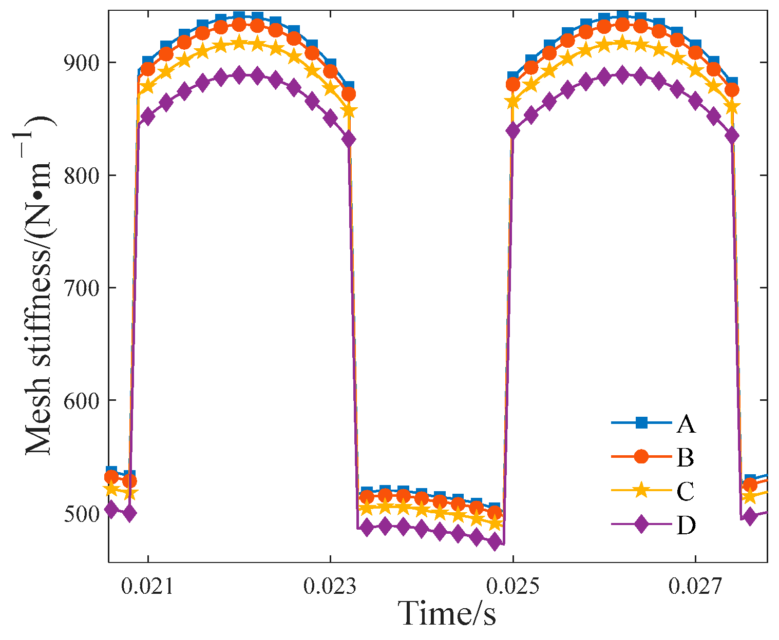
2.2. Meshing Characteristics of Fractal Rough Tooth Surface

Building upon the previous analysis, it becomes apparent that, in comparison to G, D possesses a stronger capacity for characterizing surface roughness. The fractal dimension D of a gear-machined surface typically falls within the range of 1.2 to 1.8 [29]. Referring to [29], this study chooses the relatively rough condition as 1.36 < D < 1.42, the relatively medium condition as 1.45 < D < 1.55, and the relatively smooth condition as 1.56 < D < 1.8. The specific parameters are shown in Table 2.
The Hertz contact theory is used to calculate the TVMS of the gear in the smooth state [30], which is compared with the TVMS calculation method of the fractal rough tooth surface proposed in this paper (D = 1.56, G = 10−11). The results are illustrated in Figure 3, where both the contact stiffness and the amplitude of TVMS for the fractal model exceed those of the Hertz model.
The main factor contributing to this phenomenon is that for the Hertz method, the contact force is directly applied to the smooth tooth surface to solve the gear contact stiffness, while the fractal method first solves the contact area of the uneven bodies on the gear surface by applying the contact force, then bringing it into Equation (5) to calculate the gear contact stiffness. Additionally, when gears experience faults, the tooth surface morphology changes. Therefore, the fractal method is better suited for accurately representing the changing trends in gear pair contact stiffness when faults occur.
In addition, based on Equations (5)–(7), the TVMS results for the external meshing gear pair, when the fractal parameters D and G change, can be obtained, as illustrated in Figure 4. It is evident that the TVMS of the gear pair progressively rises with the increase of D and decreases with the reduction of G. This trend signifies that the smoother the gear surface, the higher the stiffness values. In contrast to G, the fractal dimension D exerts a definitive influence on TVMS. Similarly, the variations in TVMS for the planet gear-ring gear internal meshing pair follow the same patterns. Consequently, due to space limitations, the subsequent analysis will exclusively present the results of TVMS for the sun gear-planet gear external meshing pair without further discussion of the variations in TVMS for the planet gear-ring gear internal meshing pair.

3. TVMS Calculation Model Considering Fractal Surface Contact and Gear Macro-Pitting

3.1. TVMS Calculation of Gears with Macro-Pitting Fault

In this section, the macro-pitting cross-section shape is modeled as circular, considering the presence of a single pit only. The position and dimensions of the pit are represented using three variables (u, R, and H), as shown in Figure 5, where u is the distance from the tooth root to the center of the macro-pitting crater relative to the tooth thickness, R is the radius of the macro-pitting crater center, and H is the depth of the macro-pitting crater. According to the American Society for Metals (ASM) Handbook [31], if the tooth surface has high hardness or experiences substantial contact stress, macro-pitting continues to expand, leading to an increase in both area and depth. Therefore, to further quantify the fault size, r and δ are used to represent the ratio of macro-pitting length to tooth width and the ratio of macro-pitting depth to tooth thickness, respectively. Taking the American Society for Metals (ASM) manual to classify gear macro-pitting damage levels [31] as a reference, the fault size change range discussed in this article is 5% < r > 20%, 16% < δ > 64%.
Generally, macro-pitting occurs near the tooth top or pitch line, which is caused by high contact stress and repeated rolling and sliding contact [32]. Therefore, macro-pitting has a notable impact on the stiffness segment from the tooth crest to the location of the pitting, while the stiffness of the section from the macro-pitting to the tooth root is less affected. When macro-pitting occurs in the gear, the bending stiffness Kb, shear stiffness Ks, and axial compression stiffness Ka have been changed, and their expressions are as follows:
1 K b = α 1 α 2 3 α 2 α cos α 2 E L sin α + α 2 α cos α 3 3 Δ I x R b 3 { 1 + cos α 1 ( α 2 α sin α cos α ] 2 d α
1 K s = α 1 α 2 1.2 ( 1 + v ) α 2 α cos α cos 2 α 1 E L sin α + α 2 α cos α Δ A x 2 R b d α
1 K a = α 1 α 2 α 2 α cos α sin 2 α 1 2 E L sin α + α 2 α cos α Δ A x R b d α
where E is the elastic modulus of the gear; Δ A x and Δ I x , respectively, represent the reduction in area; and the area moment of inertia when the distance between gear tooth contact points is x. The definitions of the symbols involved in Equations (8)–(10) and the specific calculation procedures can be found in [33,34].

3.2. Gear Meshing Characteristics with Macro-Pitting Fault

To investigate the influence of different fault sizes on the TVMS of gear pairs, the macro-pitting fault stiffness model presented in Section 2.1 is employed. Simulation is carried out for the TVMS of the sun gear-planet gear external meshing pair when the macro-pitting radius varies. Specifically, we keep δ at 64%, while maintaining D at 1.56 and G at 10−11. The results of TVMS changing with r from 5% to 20% are depicted in Figure 6. A detailed analysis reveals that, compared to a healthy gear pair, the amplitude of TVMS in the presence of macro-pitting faults significantly decreases. Furthermore, as r increases, the stiffness amplitude within the faulted region decreases proportionally. In the single-tooth meshing region, the gear experiences more concentrated forces, resulting in a more pronounced decrease in stiffness. Within the double-tooth meshing region, it is observed that the lengths of the corresponding fault intervals vary at different r, extending as r increases. This implies the fault impact duration is positively related to the macro-pitting radius.
Furthermore, we have investigated the influence of variations in macro-pitting depth on the TVMS of the sun gear-planet gear external meshing pair. In this analysis, r is held constant at 5%, and the surface roughness parameters are D = 1.56 and G = 10−11. Similarly, simulations are performed using the macro-pitting fault mesh stiffness calculation theory outlined in Section 2.1, and the results are presented in Figure 7. We can observe that as δ increases, the stiffness amplitudes within both the single-tooth and double-tooth meshing regions decrease. The reduction in stiffness is particularly prominent in the single-tooth meshing area. Notably, in contrast to Figure 6, when macro-pitting depth varies, the stiffness curves in the double-tooth meshing region almost entirely overlap. This observation suggests that changes in macro-pitting depth have a relatively low impact on fault sensitivity.
Finally, to highlight the significant impact of surface roughness on TVMS of gear pairs with macro-pitting faults, experiments were conducted based on the four surface roughness parameters listed in Table 2, and the results are shown in Figure 8. When comparing the TVMS curves for the four scenarios, denoted as A, B, C, and D, it becomes evident that for a constant fault size (r = 5%, δ = 64%), the smaller the fractal dimension, the rougher the tooth surface, which could lead to a more pronounced reduction in stiffness. In contrast to the observations in Figure 6 and Figure 7, it is worth noting that the variations in stiffness amplitude for faults with varying degrees of surface roughness are highly pronounced. This emphasizes the effectiveness and necessity of incorporating surface roughness considerations into the modeling of TVMS for gear pairs.

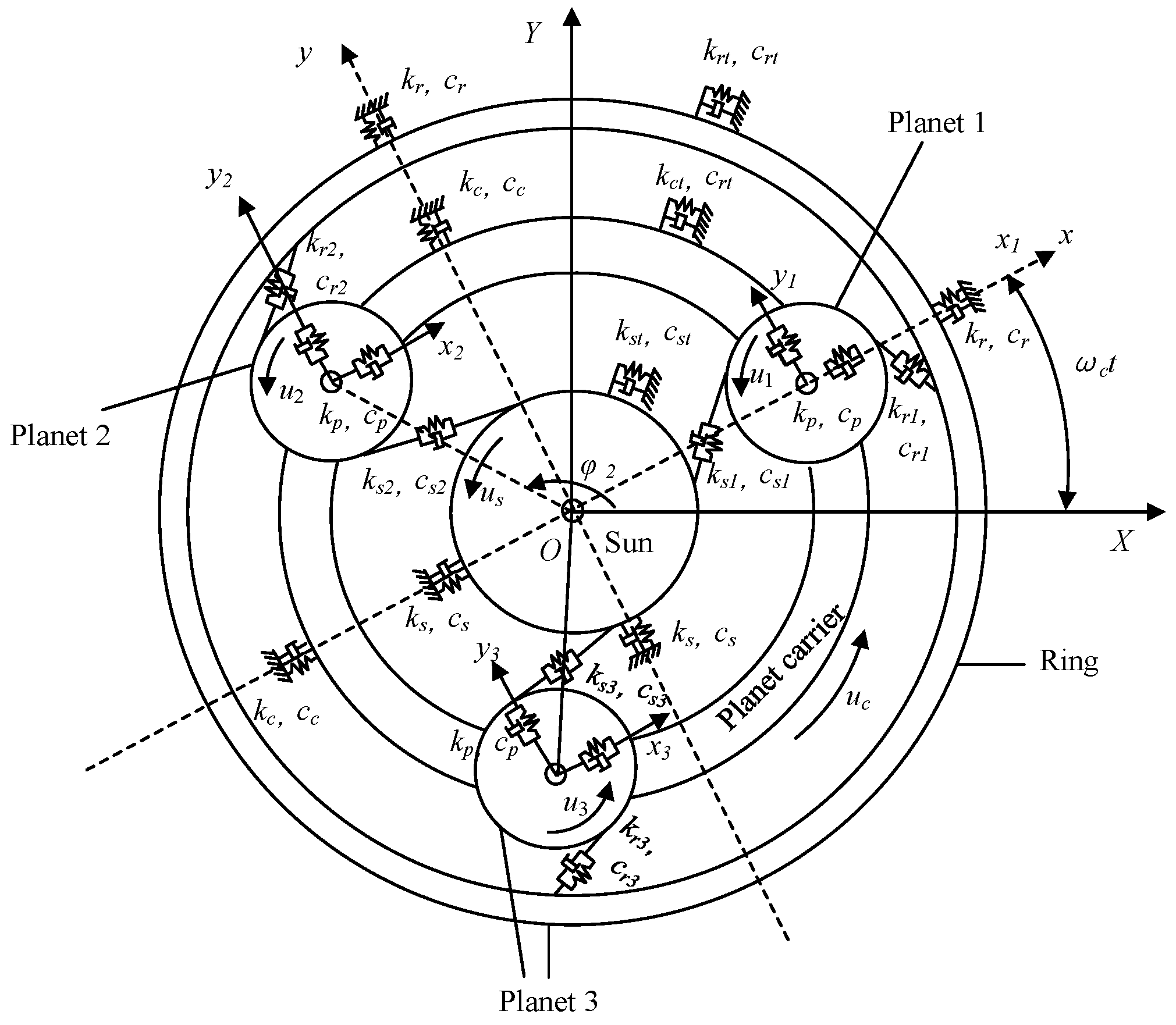
4. Planetary Gear Train Dynamics Model Considering Fractal Surface Contact

Combining the effects of TVMS and tooth side clearance on the dynamic characteristics of the planetary gear train, a lumped-parameter approach is employed to create a dynamic model, as illustrated in Figure 9. It is assumed that each component in the diagram undergoes motion in three directions: the xi and yi directions are translational motion, and the ui direction is torsional motion. Here, the subscript i (i = c, r, s, pn) represents the components, including the planet carrier, ring gear, sun gear, and the n-th planet gear (n = 1, 2, …, N), where N is the number of planet gears and N = 3.
Assuming the ring gear is fixed and the sun gear and planet carrier are the input and output components, based on Newton’s second law, the motion equations for the sun gear are:
m s x ¨ s 2 ω c y ˙ s ω c 2 x s n = 1 3 F s p n sin φ s p n + c s x ˙ s + k s x s = 0 m s y ¨ s + 2 ω c x ˙ s ω c 2 y s + n = 1 3 F s p n cos φ s p n + c s y ˙ s + k s y s = 0 I s / r s 2 u ¨ s + n = 1 3 F s p n + c s t u ˙ s + k s t u s = T s r s
In the same way, the motion equations of the ring gear, planet carrier, and planet gear can be obtained, respectively:
m r x ¨ r 2 ω c y ˙ r ω c 2 x r n = 1 3 F r p n sin φ r p n + c r x ˙ r + k r x r = 0 m r y ¨ r + 2 ω c x ˙ r ω c 2 y r + n = 1 3 F r p n cos φ r p n + c r y ˙ r + k r y r = 0 I r / r r 2 u ¨ r + n = 1 3 F r p n + c r t u ˙ r + k r t u r = 0
m c x ¨ c 2 ω c y ˙ c ω c 2 x c + n = 1 3 k p n δ c n x + c p n δ ˙ c n x + c c x ˙ c + k c x c = 0 m c y ¨ c + 2 ω c x ˙ c ω c 2 y c + n = 1 3 k p n δ c n y + c p n δ ˙ c n y + c c y ˙ c + k c y c = 0 I c / r c 2 u ¨ c + n = 1 3 k p n δ c n u + c p n δ ˙ c n u + c c t u ˙ c + k c t u c = T c r c
m p n x ¨ p n 2 ω c y ˙ p n ω c 2 x p n + F s p n sin φ s p n + F r p n sin φ r p n = c p n δ ˙ c n x + k p n δ c n x m p n y ¨ p n + 2 ω c x ˙ p n ω c 2 y p n F s p n cos φ s p n F r p n sin φ r p n = c p n δ ˙ c n y + k p n δ c n y I p n / r p n 2 u ¨ p n + F s p n F r p n = 0
where m, I, r, and T are the mass, the mass, moment of inertia, base circle radius, and external torque of the respective components. δ c n x , δ c n y , δ c n u correspond to the relative displacements of the planet carrier with respect to the planet gears in the x, y, and u directions, respectively. The F r p n , F s p n are the meshing forces between the sun gear-planet gear pair and ring gear-planet gear pair, F j = k i δ j + c j δ ˙ j (j = spn, rpn); where cj is the damping coefficient corresponding to the meshing pair. Here, kspn and krpn are the TVMS corresponding to the external meshing of the sun gear-planet gear pair and the internal meshing of the planet gear-ring gear pair, with specific calculation details provided in Section 2.1 and Section 2.2. Additionally, the parameters with subscripts k i (i = c, r, s, pn) indicate the stiffness of the bearings supporting the respective components and k i t represent the torsional stiffness of the components.
The planet carrier rotation frequency is:
ω c = ω s z s z s + z r
where zs and zr are the number of teeth of the sun gear and planet gear, respectively. The ω s is the sun gear rotation frequency, ω s = 800 60 .
The relative displacement of the sun gear-planet gear meshing pair can be expressed as:
δ s p n = x p n x s sin φ s p n + y s y p n cos φ s p n + u s + u p n + e s p n ( t )
Similarly, the relative displacement of the planet gear-ring gear meshing pair can be expressed as:
δ r p n = x p n x r sin φ r p n + y r y p n cos φ r p n + u r u p n + e r p n ( t )
Taking into account the influence of geometric errors in the actual planetary gear transmission system, we introduce e s p n and e r p n to describe the static transmission errors of the sun gear-planet gear pair and planet gear-ring gear pair, e j ( t ) = E j sin f m t + γ j T , where f m , E j , and γ j are the meshing frequency, error amplitude, and initial phase of the meshing stiffness for gear pairs, respectively [35].
Simultaneously, considering the impact of backlash on the dynamic characteristics of the gear transmission system, we introduce the backlash function, which can be denoted as:
f ( x , b ) = x b , ( x > b ) 0 , | x | b x + b , ( x < b )
where b is the backlash constant.
For the planetary gear train, the sun gear serves as the input, the sun gear meshes with the planet gear, and at the same time, the planet gear meshes with the ring gear, and finally the ring gear outputs. The meshing frequency of each gear pair is the same, which can be expressed as:
f m = ω c z r
When macro-pitting defects exist on the tooth surface of the planet gear, the planet gear rotates once, and the faulty gear teeth mesh with the sun gear and ring gear, respectively, causing fault impact. The fault characteristic frequency is expressed as:
f p c = f m z p
where zp is the number of teeth in the ring gear.

5. Model Simulation and Analysis

5.1. Dynamic Effects of Macro-Pitting Fault on the Planetary Gear Train with Surface Roughness

Based on the planetary gear train dynamic model established in Section 3, the time domain and frequency domain characteristics of the system vibration acceleration signals are examined under various macro-pitting conditions and surface roughness effects. This analysis provides a theoretical basis for the subsequent fault diagnosis of planetary gearboxes. The structural and dynamic parameters required for the model solution can be found in Table 1 and Table 3.
First, the TVMS of the gear in healthy condition and the macro-pitting fault are brought into the dynamic model, respectively. Then, we utilized the Runge-Kutta method to solve the model. Finally, as shown in Figure 10, the vibration acceleration response results of the planet gear in healthy condition and the macro-pitting fault are obtained. It is worth noting that the surface roughness parameters used are D = 1.56 and G = 10−11, while the macro-pitting fault parameters are δ = 64% and r = 15%. As can be seen from Figure 10, the vibration acceleration signals of the planet gear, both in a healthy state and with a macro-pitting fault, have impact responses caused by gear meshing in the frequency domain, which is manifested as peak frequencies corresponding to the gear meshing frequency and its harmonics k f m (k = 1, 2, 3…). The main difference is that when a planet gear experiences macro-pitting, periodic shocks appear in the vibration acceleration time domain response with an interval of 0.140625 s, corresponding to the planet gear fault frequency f p c . In the frequency domain response, side frequency bands appear in the low frequency region and near the multiplier of the meshing frequency with the planet gear fault frequency as the interval, and the frequency positions are n f p c and k f m ± n f p c (n, k, j = 1, 2…).
Given the higher sensitivity of fault impact to the macro-pitting fault radius parameter, the influence of different r on the vibration response of the planetary gear train is analyzed, considering fixed surface roughness. While keeping the surface roughness and macro-pitting depth parameters constant (D = 1.56, G = 10−11, δ = 64%), the vibration acceleration signals of the planet gear for four different fault levels with r varying from 5% to 20% are investigated, as shown in Figure 11. It can be observed that the characteristics of the planet gear vibration response are generally similar for different r, but as r increases, the response amplitude shows an increasing trend. Among them, through comparative analysis of specific spectrum details, it can be observed that the sixth-order planetary gear fault frequency 6 f p c is increased by 9% when r = 20%.

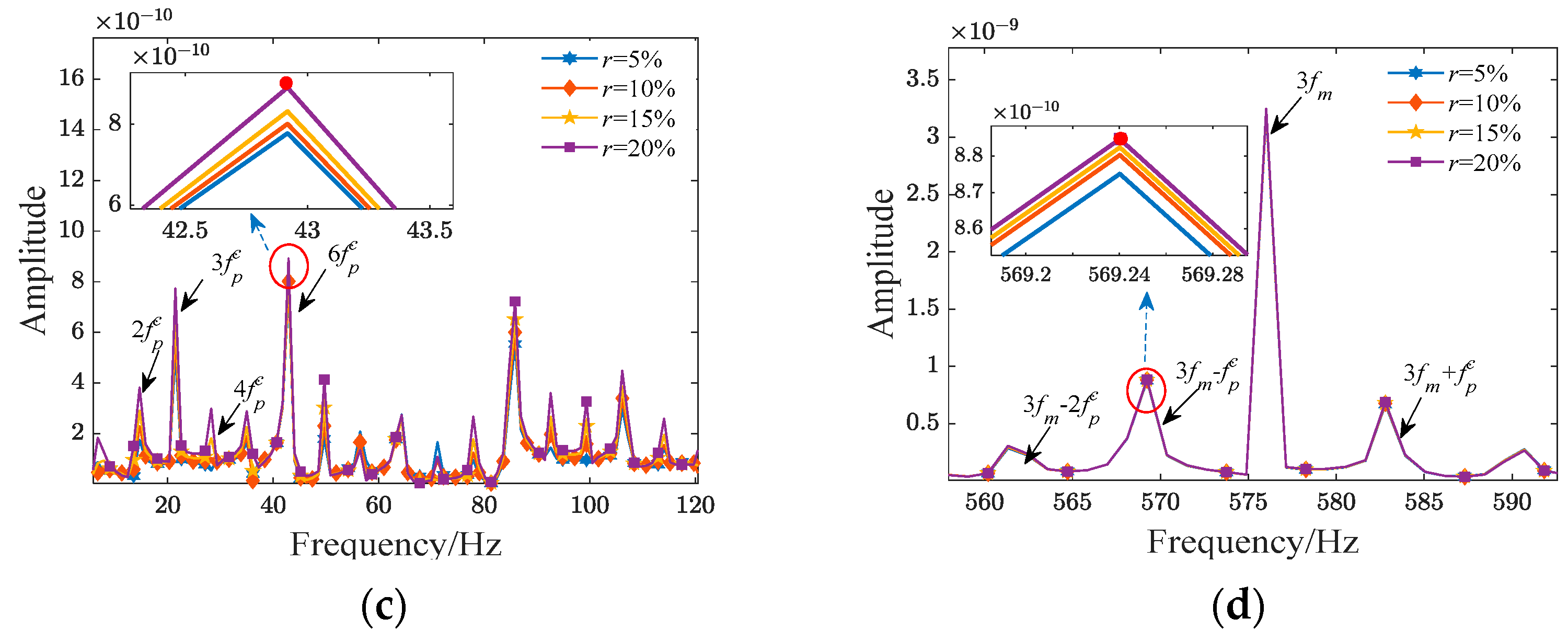
5.2. Dynamic Effects of Surface Roughness on the Planetary Gear Train with Macro-Pitting Fault

When the macro-pitting radius and depth of the planet gear are fixed, the impact of changes in surface roughness on the vibration response of the planetary gear train is explored by changing the fractal parameters D and G. Figure 12 shows the vibration acceleration signals of the planet gear when the macro-pitting fault size is δ = 64%, r = 15%, and the different roughness levels obtained based on Table 2. It can be seen from the time domain signal that the impact of planetary gear failure increases with the intensification of tooth surface roughness, with a maximum increase of nearly 6 times. From the spectrum, it can be observed that the meshing frequency and its harmonics still dominate. However, in contrast to Figure 11, surface roughness has a more significant impact on the amplitude of the planet gear vibration response. Specifically, as the tooth surface roughness increases, the frequency domain response of the planet gear changes more dramatically. Additionally, some sidebands to the left of certain meshing frequencies are higher than the frequencies themselves, such as f m , 3 f m , 8 f m . Taking the sixth-order planet gear fault frequency 6 f p c and the third-order planet gear fault frequency 3 f p c as an example, when the tooth surface roughness parameter is degree D, the peak value reaches the maximum value, which is nearly 2 times and 11 times higher than the A curve, respectively.

6. Experimental Verifications

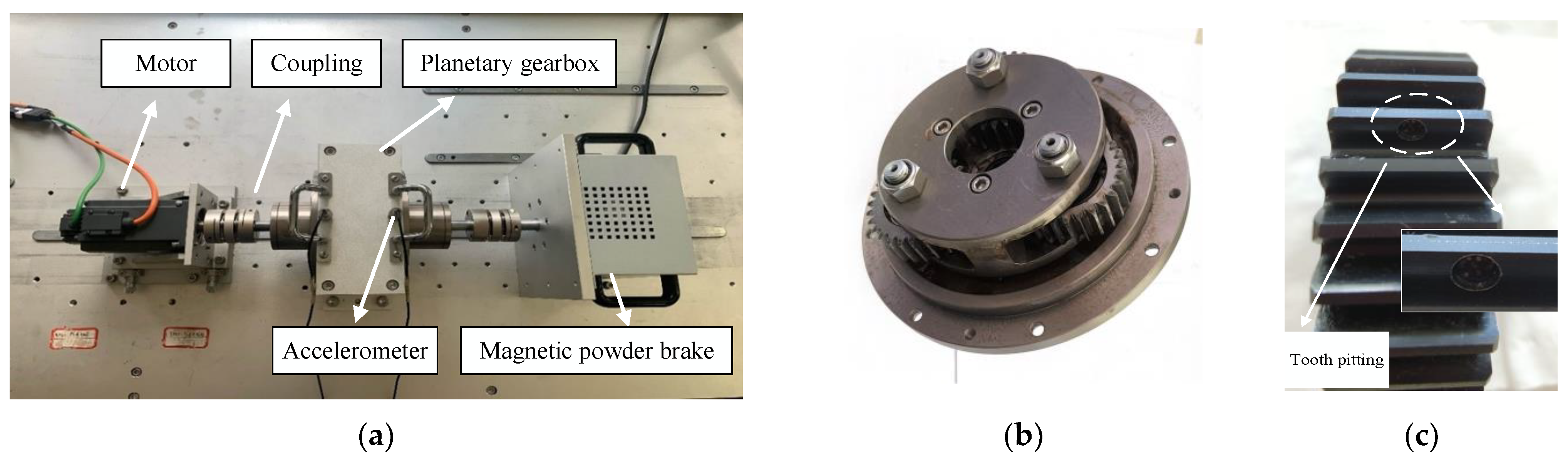
6.1. Experimental Platforms

To further verify the correctness of the planetary gear train dynamics model built in Section 3, a self-built planetary gearbox experimental platform is used to collect experimental signals of the health and fault states of the planet gear for comparative analysis. The basic parameters of the planetary gearbox are shown in Table 1, with a gear transmission ratio of 1.5, meeting the requirements for spur gear transmission and allowing the system to operate normally. The platform mainly consists of a motor, couplings, a planetary gearbox, a magnetic powder brake, and a data acquisition system, as shown in Figure 13a. Among them, the planetary gear train in the gearbox and the planet gear with macro-pitting are shown in Figure 13b,c, respectively. The fault size is δ = 64% and r = 15%. During the test, the sampling rate is set to 12,800 Hz, the rotation speed is 800 r/min, the sampling interval is 2 s, and each sampling duration is 5 s.

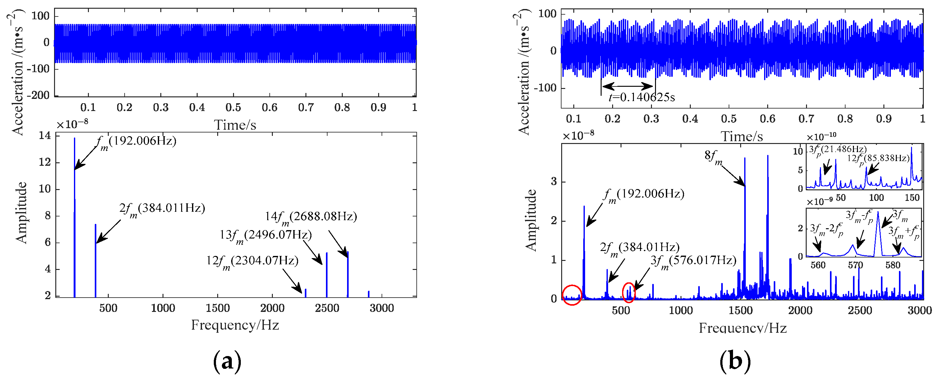
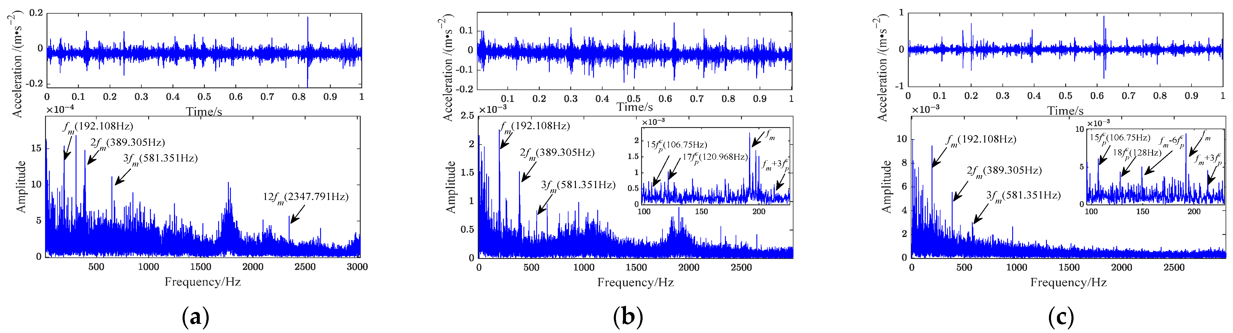
6.2. Experimental Signal Verification under Healthy and Fault Conditions

The experimental signals for the planet gear in both a healthy state and with macro-pitting fault are presented in Figure 14. Specifically, in a healthy state, due to the influence of various interference factors such as noise and transmission paths in the actual signal, the time domain signal and spectrum are more complex than the simulated signal. However, it can still be observed that the time domain signal exhibits periodic fluctuations, with the meshing frequency and its harmonics dominating the spectrum. For the macro-pitting fault experimental signal, it is evident that the time domain signal fluctuates significantly with a large amplitude. Both sides of the meshing frequency, as well as the lower frequencies, exhibit the presence of sidebands spaced at intervals of f p c , aligning with the spectral patterns of the fault simulation signal in Figure 10.
Referring to [10], a comparison was made using simulated values ( f m = 192.006 Hz), measured values ( f m = 192.108 Hz), and theoretical values ( f m = 192 Hz) of the gear meshing frequency to verify the effectiveness of the dynamic model of the planetary gear train established in this paper. The comparison results show that the error between the simulation value and the theoretical value of the meshing frequency is 0.003%, and the error between the simulation value and the measured value is 0.053%, verifying the accuracy of the model. Similarly, by comparing the values of the second-order meshing frequency and the twelfth-order meshing frequency, the errors between the experimental signal and the simulated signal are 1.36% and 1.86%, respectively. Additionally, analyzing the difference in the planet gear fault frequency between the simulated signal and the experimental signal provides proof for exploring the applicability of the dynamic model constructed in this paper to local gear faults. According to Table 4, the errors in the first four-order fault frequencies of the planet gear macro-pitting fault between the two signals are all below 5%.
Figure 14 also describes that when the gear surface roughness changes with the degree of the macro-pitting fault, the vibration response amplitude of the planetary gearbox increases. For example, taking the fifth-order planet gear fault frequency as an example, the amplitude increased by 88.6%. Subsequently, a localized amplification of the low-frequency band in simulated and experimental signals under various degrees of tooth macro-pitting faults was conducted, as illustrated in Figure 15. It can be observed that, due to interference from noise and other factors in the experimental signal, the spectrum sidebands are more complex compared to the simulated signal. However, in both the simulated and experimental signals, with the intensification of macro-pitting fault severity, there is a tendency for the frequency amplitude of the planet gear fault to increase. Furthermore, noticeable amplitude differences are observed in the spectral results between the two signals. This is mainly because the dynamic model built into this article does not consider the influencing factor of the transmission path of the gearbox vibration signal [35].
In summary, through the comparative analysis in the time domain and frequency domain, it can be found that the vibration characteristics of the simulation signal in the healthy state and fault state are basically consistent with the measured signal, which verifies the correctness of the built numerical simulation model.

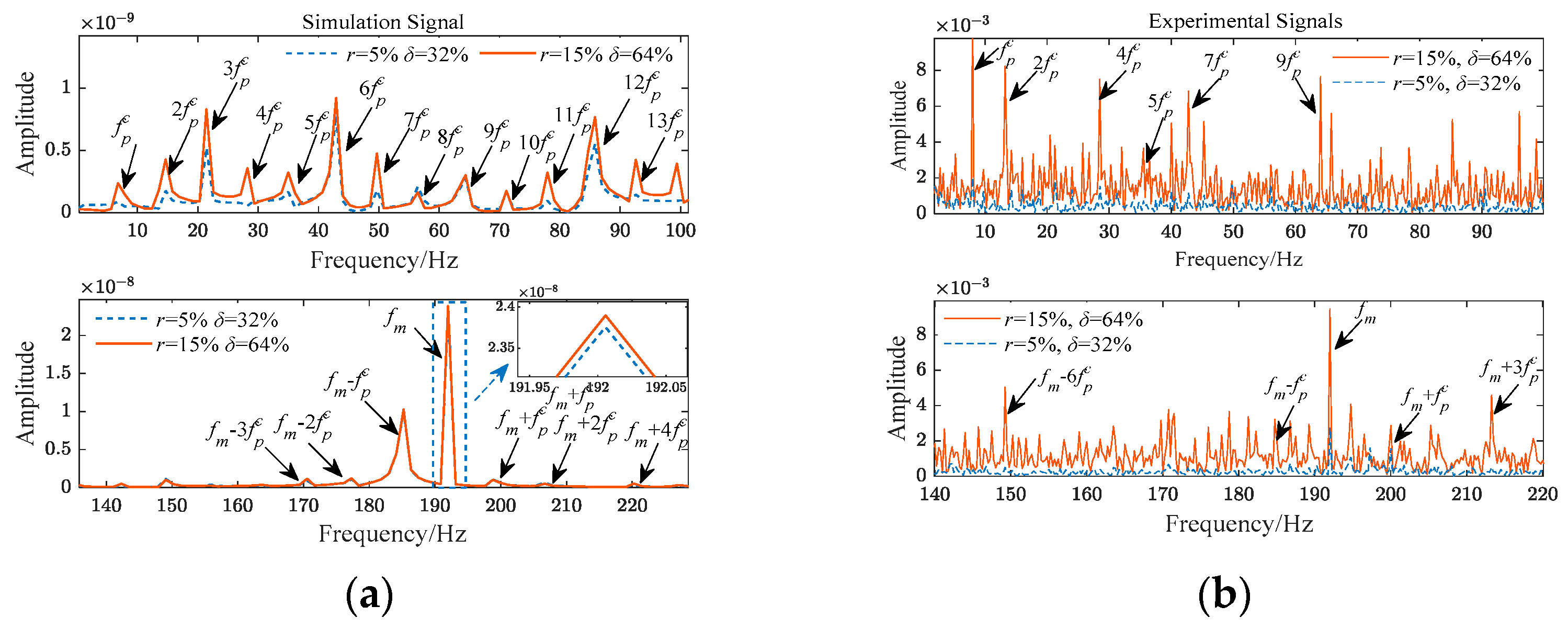
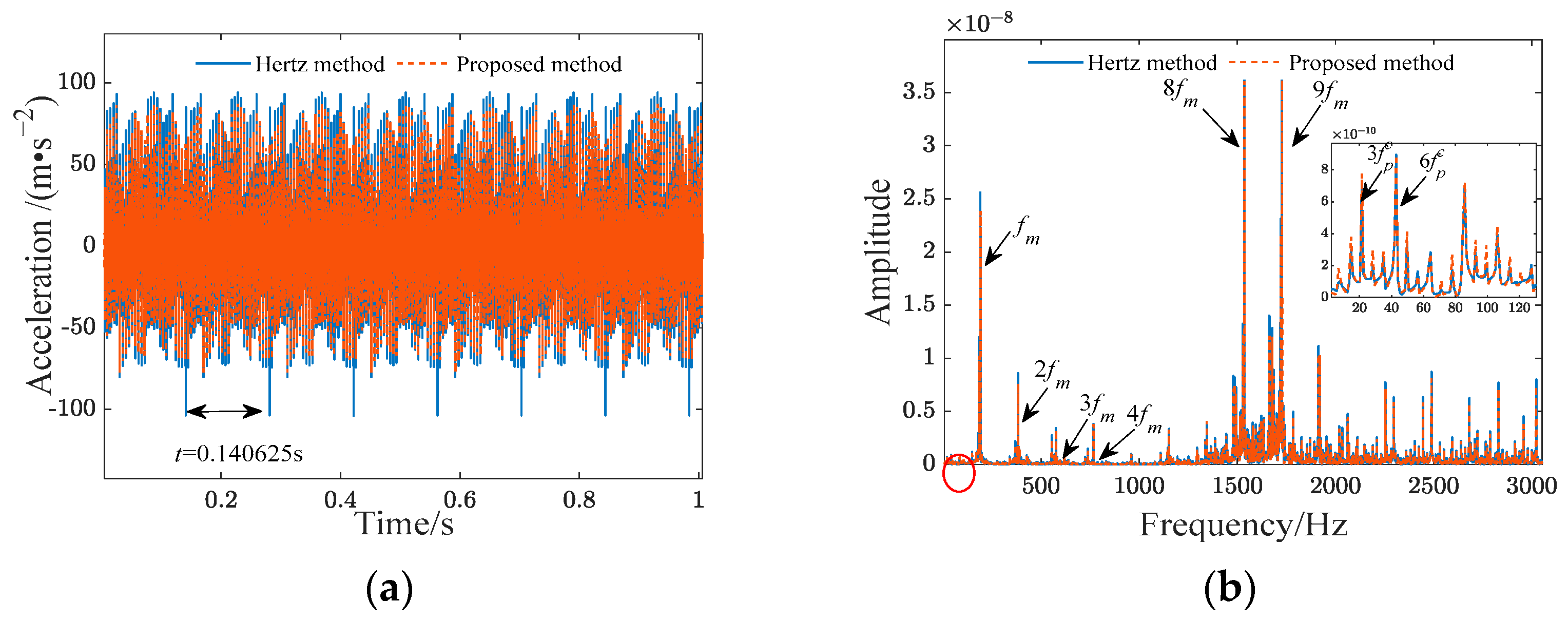
6.3. Comparative of the Model Descriptive Capability

To substantiate the efficacy of the proposed approach, a comparative study between the traditional models and the proposed model under a macro-pitting fault will be given. The proposed method is compared with the planetary gear train dynamic model constructed based on the Hertz contact theory in [36], in which the vibration response results are shown in Figure 16. After a detailed analysis, it is evident that, when compared to the model in [36], the fault feature model developed in this paper using fractal theory exhibits a 21% reduction in time domain response amplitude. In the frequency domain response, the frequency amplitude of low-order planet gear faults has increased by 26% (0–120 Hz), which means that the built model is more conducive to characterizing weak fault characteristics. Additionally, the root mean squared error (RMSE) is used to quantitatively evaluate the effectiveness of the model in this paper. The results, as shown in Table 5, show that the RMSE between the output signal of the model and the actual fault signal is 8.7% lower than the Hertz model, proving that the proposed method improves the reliability of the model.

7. Conclusions

In this paper, the influence of gear surface roughness is considered, resulting in an enhancement of the calculation model for TVMS under macro-pitting fault conditions. Subsequently, a dynamic model for the planetary gear train with macro-pitting faults is established utilizing the lumped-parameter method. By conducting numerical simulations and experimental verification of planet gear vibrations under various fault severities and surface roughness conditions, an analysis is performed to investigate the impact of surface roughness on the dynamic characteristics of planetary gear trains with macro-pitting faults. The main conclusions are as follows:
(1)
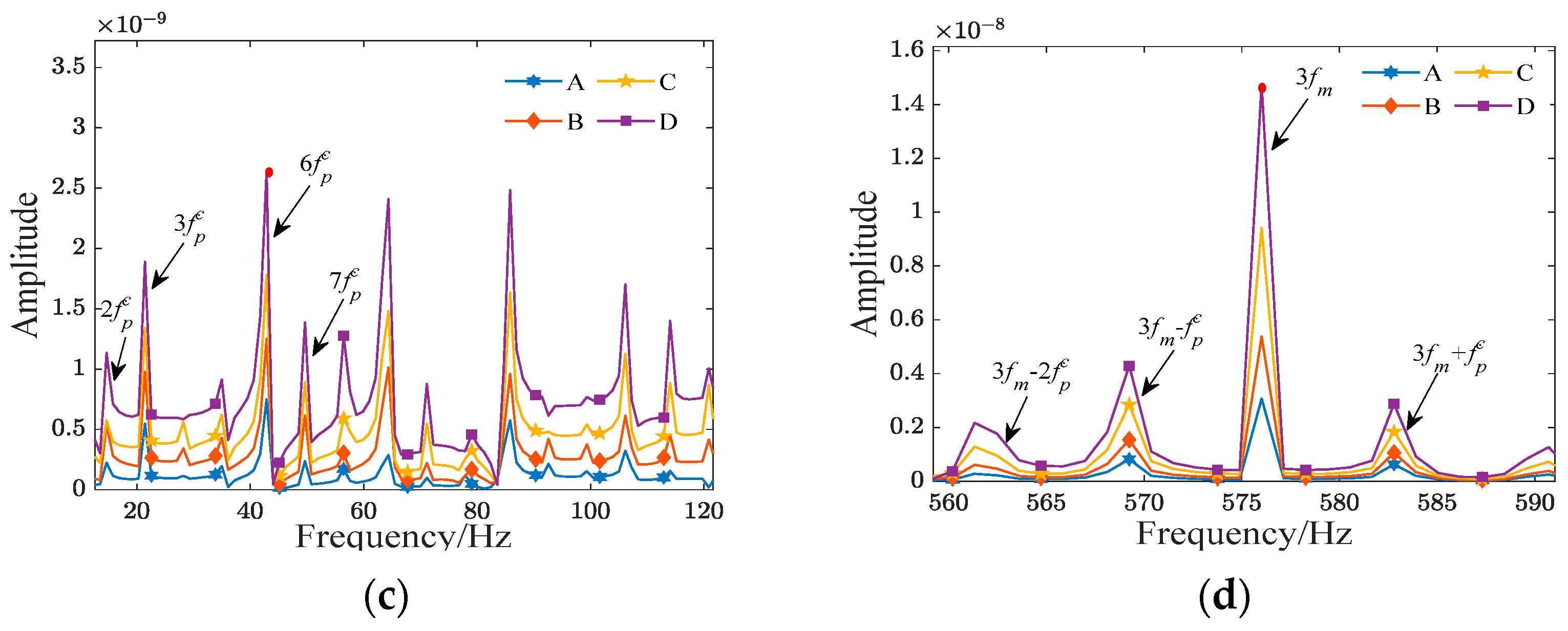
When macro-pitting occurs in the planet gear, the TVMS amplitude of the gear pair in the fault area begins to decrease. With larger fault sizes, the change in TVMS becomes more pronounced. Simultaneously, as the fractal dimension D decreases, which means the tooth surface is rougher, the decrease in TVMS becomes greater. Additionally, in the time domain, the vibration signals of the planet gear have exhibited periodic impact signals, and in the frequency domain, modulation sidebands spaced by the faulty gear rotation frequency f p c have appeared.
(2)
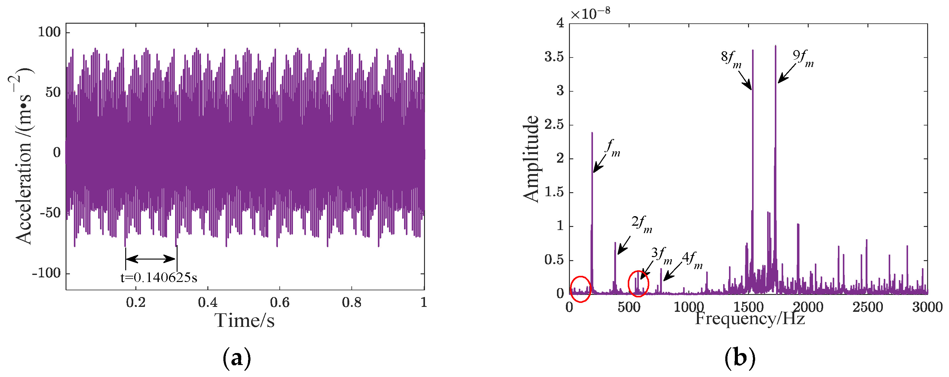
With the increasing severity of gear macro-pitting faults and the worsening of tooth surface roughness, the fault characteristic amplitude is increased. When the surface is relatively rough, there is a phenomenon in the spectrum where some meshing frequency modulation sidebands, spaced at intervals corresponding to the gear’s rotation frequency f p c , appear to be higher than the meshing frequency. Therefore, when analyzing the fault dynamic characteristics of the planetary gear train, consideration of surface roughness is indispensable.
Based on the constructed dynamic model of the planetary gear train, this paper preliminarily explores the impact of comprehensive consideration of the two factors of gear macro-pitting failure size and surface roughness on the dynamic response of the planetary gear train. Future research will further delve deeper into the coupling effects between tooth surface macro-pitting and surface roughness, aiming to achieve rapid identification of macro-pitting faults in the planetary gear train. Moreover, in our forthcoming research, we will include an analysis of the modulating effects caused by flexible transmission paths connecting meshing points and sensor points on the gearbox casing. This is aimed at achieving a more accurate alignment with the vibration characteristics of the actual gearbox system and reducing amplitude differences between the simulated and real signals.

Author Contributions

Conceptualization, R.L. and J.M.; methodology, R.L.; software, R.L.; validation, R.L., M.Z. and J.M.; formal analysis, R.L.; investigation, R.L.; resources, J.M. and X.X.; data curation, R.L. and M.Z.; writing—original draft preparation, R.L.; writing—review and editing, J.M.; visualization, X.X.; supervision, J.M. and X.X.; project administration, J.M. and X.X.; funding acquisition, J.M. and X.X. All authors have read and agreed to the published version of the manuscript.

Funding

This research was funded by National Natural Science Foundation of China (grant numbers 62163020 and 62173168), the Major Science and Technology Projects of Yunnan Province (grant number 202202AD080005) and Kunming University of Science and Technology “Double First-Class” Science and Technology Project (grant number 202202AG050002).

Data Availability Statement

The data presented in this study are available on request from the corresponding author. The data are not publicly available due to privacy reasons.

Conflicts of Interest

The authors declare no conflict of interest.

Nomenclature

GThe rough surface height parameter Δ A x The reduction in the area when the distance between gear tooth contact points is x
DFractal dimensionmMass
lThe length of a single asperityIMoment of inertia
a c Critical contact area of asperityrBase circle radius
RThe radius of curvature of the tipTExternal torque
KThe correlation coefficient between the surface hardness and the yield strength of the materialc, s, r, pPlanet carrier, sun gear, ring, and planet gear
ϕ The material property parameter δ c n x , δ c n y , δ c n u Relative displacements of the plane carrier with respect to the planet gears in the x, y, and u directions
λ B The gear surface contact coefficient F r p n , F s p n Meshing forces between the sun gear-planet gear pair and ring-planet gear pair
a l The maximum contact area k s p n , k r p n The TVMS corresponding to the external meshing of the sun gear-planet gear pair and the internal meshing of the planet gear-ring gear pair
LTooth width c j Damping coefficient corresponding to meshing pair
R1, R2The radius of curvature of the gears k i Stiffness of the bearings supporting the respective components
E The integrated modulus of elasticity k i t Torsional stiffness of the components
n ( a ) The area distribution function of asperity ω c , ω s Rotational frequencies of the planet carrier and sun gear
A r * Dimensional true contact area δ s p n , δ r p n The relative displacement of the sun gear-planet gear meshing pair and planet gear-ring gear pair
a c * Dimensional critical contact area e s p n , e r p n Static transmission errors of the sun gear-planet gear meshing pair and planet gear-ring gear pair
K h Dimensional-normal contact stiffnessbBacklash constant
KbBending stiffnesszs, zp, zrThe number of teeth of the sun gear, planet gear, and ring gear
KsShear stiffness f m Meshing frequency
KaAxial compression stiffness f p c Fault frequency of the planet gear
KfFlexible deformation stiffnessrThe ratio of macro-pitting length to tooth width
α The gear rotation angleδThe ratio of macro-pitting depth to tooth thickness
α 2 The half-tooth angle on the base circleTVMSTime-varying meshing stiffness
α 1 The contact angle corresponding to the gear meshing point
EThe elastic modulus of the gear
vPoisson’s ratio
RbBase circle radius
Δ I x The reduction in area moment of inertia when the distance between gear tooth contact points is x

References

  1. Liang, X.; Zuo, M.J.; Feng, Z. Dynamic modeling of gearbox faults: A review. Mech. Syst. Signal Process. 2018, 98, 852–876. [Google Scholar] [CrossRef]
  2. Meng, Z.; Shi, G.; Wang, F. Vibration response and fault characteristics analysis of gear based on time-varying mesh stiffness. Mech. Mach. Theory 2020, 148, 103786. [Google Scholar] [CrossRef]
  3. Wang, Z.G.; He, W.P.; Liao, N.N.; Dou, Y.H.; Guo, B.L. Study on vibration response mechanism of tooth root crack and tooth surface spalling fault. J. Xidian Univ. 2021, 48, 131–137. [Google Scholar]
  4. Liang, X.H.; Zhang, H.S.; Liu, L.B.; Zuo, M.J. The influence of tooth pitting on the mesh stiffness of a pair of external spur gears. Mech. Mach. Theory 2016, 106, 1–15. [Google Scholar] [CrossRef]
  5. Concli, F.; Kolios, A. Preliminary evaluation of the influence of surface and tooth root damage on the stress and strain state of a planetary gearbox: An innovative hybrid numerical-analytical approach for further development of structural health monitoring models. Computation 2021, 9, 38. [Google Scholar] [CrossRef]
  6. Sheng, L.; Ahmet, K. Scuffing model for spur gear contacts. Mech. Mach. Theory 2021, 156, 104161. [Google Scholar]
  7. Brumercik, F.; Lukac, M.; Caban, J.; Krzysiak, Z.; Glowacz, A. Comparison of selected parameters of a planetary gearbox with involute and convex–concave teeth flank profiles. Appl. Sci. 2020, 10, 1417. [Google Scholar] [CrossRef]
  8. Drechsel, A.; Constien, L.; Pellkofer, J.; Boiadjiev, I.; Karsten, S. Extended calculation method for determining the pitting load carrying capacity of bevel and hypoid gears. Forsch. Im Ingenieurwesen 2022, 86, 829–844. [Google Scholar] [CrossRef]
  9. Constien, L.; Drechsel, A.; Pellkofer, J.; Reimann, T.; Karsten, S. Consideration of the influences of the driving direction within the calculation of the pitting load-carrying capacity of bevel and hypoid gears. J. Braz. Soc. Mech. Sci. 2023, 45, 523–538. [Google Scholar] [CrossRef]
  10. Chen, Y.; Li, J.K.; Zang, L.B.; Liu, Y.Q.; Bi, W.Y.; Yang, X.P. Experimental study on dynamic simulation pre-diction and fault identification of fatigue pitting helical gear. J. Mech. Eng. Chin. Ed. 2021, 57, 61–70. [Google Scholar]
  11. Wang, S.Y.; Zhu, R.P. Research on dynamics and failure mechanism of herringbone planetary gearbox in wind turbine under gear surface pitting. Eng. Fail. Anal. 2023, 146, 107130. [Google Scholar] [CrossRef]
  12. Gao, C.W.; Liu, W.Z.; Zhu, R.P.; Wang, H.Y. Dynamic Characteristics and experimental study of gears based on evolution of tooth pitting. J. Eng. Therm. Energy Power 2023, 38, 125–130. [Google Scholar]
  13. Han, H.Z.; Zhao, Z.F.; Tian, H.X.; Ma, H.; Yang, Y.; Li, X. Fault feature analysis of planetary gear set influenced by cracked gear tooth and pass effect of the planet gears. Eng. Fail. Anal. 2021, 121, 105162. [Google Scholar] [CrossRef]
  14. Shen, Z.X.; Qiao, B.J.; Yang, L.H.; Luo, W.; Yang, Z.B.; Chen, X.F. Fault mechanism and dynamic modeling of planetary gear with gear wear. Mech. Mach. Theory 2021, 155, 104098. [Google Scholar] [CrossRef]
  15. Sheng, Z.Y.; Zhang, Z.; WANG, Y.R.; Li, H.K. Analysis of transmission characteristics of sun wheel root cracks in planetary wheel gearboxes. China Mech. Eng. 2023, 34, 2177–2185. [Google Scholar]
  16. Majumdar, A.A.; Bhushan, B. Role of fractal geometry in roughness characterization and contact mechanics of surfaces. Trans. ASME J. Tribol. 1990, 112, 205–216. [Google Scholar] [CrossRef]
  17. Wang, X.P.; Liu, S.J. Fractal prediction model of normal contact stiffness of micro-pitting gear. J. Mech. Eng. Chin. Ed. 2021, 57, 68–76. [Google Scholar] [CrossRef]
  18. Zhao, Z.F.; Han, H.Z.; Wang, P.F.; Ma, H.; Yang, Y. An improved model for meshing characteristics analysis of spur gears considering fractal surface contact and friction. Mech. Mach. Theory 2021, 158, 104219. [Google Scholar] [CrossRef]
  19. Wu, J.Z.; Xiao, H.F.; Yang, D.B. Time-varying meshing stiffness algorithm and characteristic analysis of gear rough interface. J. Vib. Meas. Diagn. 2022, 42, 56–61+194. [Google Scholar]
  20. Chen, L.; Fan, Z.M.; Yin, Z.M. Fractal model of double involute gears time-varying meshing stiffness considering friction factors. Tribology 2023, 43, 358–367. [Google Scholar]
  21. Lan, G.S.; Ji, C.L.; Li, X.; Li, S.Q.; Li, Y.; Yang, Q. Normal contact stiffness model of mixed lubrication joint surface. J. Vib. Shock 2023, 42, 220–227. [Google Scholar]
  22. Du, X.; Chen, B.K.; Liu, R.R.; Li, C.Y. Research on fractal model of load distribution and axial Stiffness of planetary roller screw mechanism considering surface roughness and friction factor. Adv. Theory Simul. 2022, 5, 2100399. [Google Scholar] [CrossRef]
  23. Li, X.P.; Mou, J.X.; Pan, W.J.; Wen, B.C. Influence of fractal backlash on dynamic behavior of gear-bearing system. J. Mech. Eng. Chin. Ed. 2018, 54, 153–160. [Google Scholar] [CrossRef]
  24. Li, X.P.; Xv, J.C.; Pan, W.J.; Mou, J.X.; Wang, L.L.; Yang, Z.M.; Wen, B.C. Dynamics of gear transmission system with fractal meshing stiffness on tooth surface. J. Harbin Inst. Technol. 2019, 51, 56–62. [Google Scholar]
  25. Meng, F.S.; Xia, H.; Zhang, X.; Wang, J.X.; Jin, Y.L. Study on nonlinear dynamic characteristics of gear system with 3D anisotropic rough tooth surface based on fractal theory. Int. J. Non Linear Mech. 2023, 150, 104366. [Google Scholar] [CrossRef]
  26. Stanojević, M.; Tomović, R.; Ivanović, L.; Stojanović, B. Critical analysis of design of ravigneaux planetary gear Trains. Appl. Phys. Lett. 2022, 7, 32–44. [Google Scholar] [CrossRef]
  27. Miladinović, S.; Veličković, S.; Novaković, M. Application of taguchi method for the selection of optimal parameters of planetary driving gear. Appl. Phys. Lett. 2016, 1, 98–104. [Google Scholar]
  28. Blagojevic, M.; Marjanovic, N.; Djordjevic, Z.; Stojanovic, B.; Marjanovic, V.; Vujanac, R.; Disic, A. Numerical and experimental analysis of the cycloid disc stress state. Teh. Vjesn. 2014, 21, 377–382. [Google Scholar]
  29. Yu, X.; Sun, Y.Y.; Li, H.G.; Wu, S.J. An improved meshing stiffness calculation algorithm for gear pair involving fractal contact stiffness based on dynamic contact force. Eur. J. Mech. A Solids 2022, 94, 104595. [Google Scholar] [CrossRef]
  30. Luo, W.; Qiao, B.; Shen, Z.X.; Yang, Z.B.; Cao, H.R.; Chen, X.F. Investigation on the influence of spalling defects on the dynamic performance of planetary gear sets with sliding friction. Tribol. Int. 2021, 154, 106639. [Google Scholar] [CrossRef]
  31. Blau, P.J. Friction, Lubrication, and Wear Technology; ASM International: Materials Park, OH, USA, 1992. [Google Scholar] [CrossRef]
  32. Feng, K.; Smith, W.A.; Borghesani, P.; Randall, R.B.; Peng, Z. Use of cyclostationary properties of vibration signals to identify gear wear mechanisms and track wear evolution. Mech. Syst. Signal Process. 2020, 150, 107258. [Google Scholar] [CrossRef]
  33. Dai, H.; Long, X.H.; Chen, F.; Xun, C. An improved analytical model for gear mesh stiffness calculation. Mech. Mach. Theory 2021, 159, 104262. [Google Scholar] [CrossRef]
  34. Shen, Z.X.; Qiao, B.J.; Yang, L.H.; Luo, W.; Chen, X.F. Evaluating the influence of tooth surface wear on TVMS of planetary gear set. Mech. Mach. Theory 2019, 136, 206–223. [Google Scholar] [CrossRef]
  35. Hu, J.; Hu, N.; Yang, Y.; Zhang, L.; Shen, G. Nonlinear dynamic modeling and analysis of a helicopter planetary gear set for tooth crack diagnosis. Measurement 2022, 198, 111347. [Google Scholar] [CrossRef]
  36. Xiang, L.; Gao, N.; Hu, A.J. Dynamic analysis of a planetary gear system with multiple nonlinear parameters. J. Comput. Appl. Math. 2017, 327, 325–340. [Google Scholar] [CrossRef]
Figure 1. The contact diagram of the gear pair when the surface is rough.
Actuators 13 00001 g001
Figure 2. Normal contact stiffness under different fractal parameters: (a) D as the parameter variable; (b) G as the parameter variable.
Actuators 13 00001 g002
Figure 3. Stiffness comparison between rough surface and smooth surface: (a) normal contact stiffness; (b) mesh stiffness.
Actuators 13 00001 g003
Figure 4. Meshing stiffness of external gear pairs under different fractal parameters: (a) D as the parameter variable; (b) G as the parameter variable.
Actuators 13 00001 g004
Figure 5. Tooth modeling with a single pit.
Actuators 13 00001 g005
Figure 6. The mesh stiffness of the external gear pair when the macro-pitting radius of the planetary gear changes.
Actuators 13 00001 g006
Figure 7. The mesh stiffness of the external gear pair when the macro-pitting depth of the planetary gear changes.
Actuators 13 00001 g007
Figure 8. The mesh stiffness of the external gear pair when the planetary gear is macro-pitting under different roughnesses.
Actuators 13 00001 g008
Figure 9. Translational-rotational model of the planetary gear train.
Actuators 13 00001 g009
Figure 10. Time-frequency domain waveform of planet gear vibration acceleration simulation signal: (a) gear health; (b) gear macro-pitting.
Actuators 13 00001 g010
Figure 11. Vibration acceleration signal of planet gear under the influence of different r: (a) time domain; (b) frequency domain; (c) Spectrum: 0–120 Hz; (d) Spectrum: 560–590 Hz.
Actuators 13 00001 g011aActuators 13 00001 g011b
Figure 12. Vibration acceleration signal of planetary gear under the influence of different roughness of tooth surface: (a) time domain; (b) frequency domain; (c) Spectrum: 0–120 Hz; (d) Spectrum: 560–590 Hz.
Actuators 13 00001 g012aActuators 13 00001 g012b
Figure 13. Planetary gearbox experimental platform: (a) experimental test rig; (b) planetary gear assembly; (c) planet gear with macro-pitting.
Actuators 13 00001 g013
Figure 14. Time-frequency domain waveform of the planet gear vibration acceleration experimental signal: (a) gear health; (b) gear macro-pitting size: r = 5%, δ = 32%; (c) gear macro-pitting size: r = 15%, δ = 64%.
Actuators 13 00001 g014
Figure 15. Partial sideband amplitude comparison of experimental signals and simulation signals: (a) experimental signals; (b) simulation signals.
Actuators 13 00001 g015
Figure 16. Vibration acceleration signals of the planet gear macro-pitting under two different modeling methods: (a) time domain; (b) frequency domain.
Actuators 13 00001 g016
Table 1. Structural parameters of planetary gear trains.
ParametersPlanetSunRing
Teeth Numbers182772
Modulus2 mm
Pressure angle20°
Tooth width20 mm
Young’s modulus2.06 × 105 MPa
Poisson’s ratio0.3
Material yield strength835 MPa
Table 2. Fractal parameters corresponding to different degrees of tooth surface roughness [18].
Surface RoughnessDG
A1.5610−11
B1.51952.0014 × 10−9
C1.44077.8357 × 10−10
D1.37972.5723 × 10−10
Table 3. Dynamic parameters of the planetary gear train.
ParametersValue
Sun gear speed (r/min) n s = 800
Bearing support stiffness (N/m) k s = k r = k c = k p = 1.0 × 10⁸
Torsional stiffness (N/m) k r t = 1.0 × 10⁸; k s t = k c t = 0
Meshing frequency (Hz) f m = 192
Planet gear fault frequency (Hz) f p c = 7
Table 4. Comparison of the fault frequency of the planet gear in the low-frequency band.
1st Harmonic2nd Harmonic3rd Harmonic4th Harmonic5th Harmonic
Simulation value7.111 Hz14.682 Hz21.486 Hz28.236 Hz35.013 Hz
Experimental value7.162 Hz14.25 Hz21.25 Hz28.5 Hz35.5 Hz
Error0.712%3.031%1.111%0.926%1.372%
Table 5. The error analysis of the output fault signal and the measured signal of the two modeling methods.
Modeling MethodProposed MethodHertz Method [36]
RMSE16.718.3
Disclaimer/Publisher’s Note: The statements, opinions and data contained in all publications are solely those of the individual author(s) and contributor(s) and not of MDPI and/or the editor(s). MDPI and/or the editor(s) disclaim responsibility for any injury to people or property resulting from any ideas, methods, instructions or products referred to in the content.

