Article

Research on the Anti-Swing Control Methods of Dual-Arm Wheeled Inspection Robots for High-Voltage Transmission Lines

1
School of Mechanical Engineering, Hubei University of Technology, Wuhan 430068, China
2
Hubei Key Laboratory Modern Manufacturing Quality Engineering, School of Mechanical Engineering, Hubei University of Technology, Wuhan 430068, China
3
Substation Intelligent Operation and Maintenance Experimental Laboratory, State Grid Hunan Ultra High Voltage Substation Company, Changsha 420100, China
4
School of Electrical Engineering, Changsha University of Science and Technology, Changsha 410114, China
*
Author to whom correspondence should be addressed.
Actuators 2023, 12(12), 472; https://doi.org/10.3390/act12120472
Submission received: 4 November 2023 / Revised: 11 December 2023 / Accepted: 12 December 2023 / Published: 18 December 2023
(This article belongs to the Section Actuators for Robotics)

Abstract

:
This paper presents an anti-swing control method to prevent situations where inspection robots detach and fall off transmission lines during obstacle crossing due to excessive swing angles caused by the rotation of the robot around the transmission line. Firstly, an obstacle-crossing model for the inspection robot was constructed and the causes of robot swinging phenomena were analyzed, in addition to their impact on obstacle crossing stability. By combining this with the obstacle-crossing model, a moment balance equation was established for the inspection robot. This equation can be used to solve mapping relationships between body offset and the tilt angle of transmission line gripping arms. We propose an anti-swing control strategy by adjusting the angle of the transmission line gripping arm’s pitching joint to make the body offset approach zero, and by utilizing the advantages of fuzzy logic in the fuzzy PID algorithm compared with the traditional PID algorithm, it can adaptively avoid the occurrence of robot swinging phenomena. The experimental results of obstacle-crossing experiments under no wind and wind turbulence conditions indicated that the proposed anti-swing control method in this study can effectively keep the body offset to within 3 mm. Compared with the methods of not using anti-swing control and using traditional PID anti-swing control, in the absence of wind effects, the peak values of body offset were reduced by 96.53% and 18.85%, respectively. Under the influence of wind turbulence, the peak values of body offset were reduced by 97.02% and 27.12%, respectively. The effectiveness of the anti-swing control method proposed in this paper has thus been verified.

1. Introduction

The purpose of high-voltage transmission line inspection is to monitor the operation status of the transmission line, identify and record the problems or defects along the electrical facilities and corridors in a timely manner, and provide necessary databases for subsequent transmission line maintenance work. Compared with traditional manual inspection methods, using robots for inspecting transmission lines have the benefits of lower inspection costs, excellent safety levels, and simpler operation [1,2,3,4]. When dual-arm wheeled inspection robots are performing obstacle-crossing tasks, they often operate in a single-arm transmission line grasping mode. However, when the tilt angle of the other arm exceeds a certain threshold, it is prone to the phenomenon of the robot’s body swinging around the transmission line, which leads to significant deviation error between the actual running path of the offline arm’s walking wheel and the preset trajectory, resulting in collisions with the transmission line or along-line electrical fixtures and failed transmission line grasping. In severe cases, it may even lead to safety accidents such as the robot arm detaching from the transmission line or falling. Therefore, researching anti-swing control strategies for robots during obstacle-crossing procedures is crucial.
Yue, X. [5] designed a new type of inspection robot that utilizes a centroid adjustment mechanism to reduce the swing amplitude of the robot during obstacle crossing. Wu, H. [6] proposed a hybrid anti-swing control technique for a power line tunnel inspection robot, which avoids excessive swinging during acceleration and deceleration processes. Two active dampening techniques were presented by Wang, S.H. [7] to reduce the load swing of a parallel transmission-line-driven robot with three degrees of freedom. Wu, G.P. [8] proposed a robust μ synthesis control method for robots based on structural singular value theory, aiming to enhance the robot’s adaptability to disturbances caused by structural changes during switching between different operational functionalities. Jiang, W. [9] presented a robust stabilizing control method for a flexible wire-powered maintenance robot under wind loads. This method dynamically controls the clamping force of the robot’s dual-arm jaws, achieving robust stabilizing control under varying levels of wind loads. Inspired by the locomotion of worms, Lima, E.J. [10] designed a mechanical robot structure. By mimicking the movement of a worm, the robot smoothly traverses obstacles by descending a set of claws along a suspended transmission line, achieving stable obstacle crossing. Bo Xu [11] introduced a novel three-arm inspection robot design. During inspections, the robot controls at least two arms to simultaneously rest on transmission lines, enabling the robot to cross obstacles with minimal oscillation. Goncalves, R.S. [12] proposed a robot capable of suspended movement on power lines. The robot controls its leg length as the “optimal leg length” during obstacle traversal, ensuring stability. In summary, the robot designed by Yue, X. ensures the stability of the robot’s posture and reduces the deformation of the transmission line through the center of gravity adjustment mechanism. The hybrid anti-swing control scheme proposed by Wu, H. enhances the robustness of the anti-swing control system for robots in tunnel environments. Wang, S. H.’s two active damping methods can naturally and smoothly reduce load oscillation. Wu, G.P.’s robust μ synthesis control method for robots based on structural singular value theory can achieve improved performance robustness against the perturbations caused by its own structural changes when switching between different operational functions. Jiang, W.’s robust stability control method for flexible-wire power can effectively mitigate the impact of substantial disturbance information, such as wind load, on robot motion control. The robot designed by Lima, E.J. combines biological and engineering principles with a novel structure; however, the obstacle-crossing process is complex. Bo Xu’s robot design enables efficient obstacle traversal. On the other hand, the robot structure proposed by Goncalves, R.S. is simple and lightweight, but susceptible to oscillations under wind forces.
Anti-swing control has many applications in the field of engineering machinery. Jensen [13] reduced the swing of a load crane by implementing a two-degrees-of-freedom anti-swing controller. Yu, W. [14] proposed an anti-swing control approach that incorporates PID control alongside neural compensation, demonstrating the local asymptotic stability of the anti-swing neural PID control. Chen, H.L. [15] presented a model predictive control (MPC)-based non-zero initial state anti-swing method, which enables a lifting device to achieve a secure anti-swing stop state by following a reference route. Li, X.O. [16] introduced a bridge crane anti-swing control strategy by incorporating a high-gain observer to estimate joint velocities and implementing PD control to reduce swing. For controlling the anti-swing and placement of a 2D under-actuated bridge crane, Gu, X.T. [17] developed a moving sliding mode control approach built on a time-dependent gain extended state observer (ESO). Wang, J.L. [18] addressed the anti-swing problem of ship-mounted jib cranes by proposing a parallel anti-swing method with three degrees of freedom for main and auxiliary transmission lines to reduce swing. Sun [19] utilized an LQR controller built on the enhanced grey wolf algorithm to reduce the swing of a ship-mounted crane and improve response speed. Li, G. [20] presented a full-state constrained obstacle crossing optimal trajectory planning strategy based on time polynomials for a dual-pendulum tower crane, which avoids obstacles while suppressing swinging of the jib and hook. In summary, Jensen, Li, X.O., and Gu, X.T.’s methods involve advanced observers or gain systems, which enhance the system’s robustness against swing and disturbances. The methods proposed by Yu, W. and Chen, H.L. combine neural compensation and model predictive control, improving the dynamic performance and control accuracy of the system. The strategies proposed by Wang, J.L. and Sun are specific to ship-mounted jib cranes, limiting their application scope. Li, G.’s proposed time polynomial strategy not only minimizes the lifting time of the crane transportation as much as possible, but also ensures the satisfaction of full state constraints and avoidance requirements.
In the field of unmanned aerial vehicles (UAVs), anti-swing control also has many applications. Sanchez [21] proposed a nonlinear controller with a hierarchical scheme to reduce load oscillations in cargo UAVs. Zhang, D. [22] presented a quadrotor anti-swing control scheme using feedforward controllers, and then used it to develop a posture visual measuring scheme based on a quadrotor suspension system model, effectively suppressing load swing. Omar, H.M. [23] applied a load-swing-angle-based anti-swing controller with delayed feedback in a hardware-in-the-loop setup to alleviate suspension load oscillations. Shi, D. [24] proposed a method for mitigating disturbances with high precision built on harmonic extended state observer (HESO), enhancing the robustness of quadrotor aircraft under suspended load influence. Yang, Y.X. [25] proposed a modeling, control, and trajectory planning method for a quadrotor with an adjustable transmission-line-suspended system. The generated flight trajectory served as a desired input for the control system, aiming to minimize load oscillations. In summary, the hierarchical nonlinear controller proposed by Sanchez, the attitude visual measurement scheme proposed by Zhang, D., the delayed feedback anti-swing controller proposed by Omar, H.M., the harmonic extension state observer scheme proposed by Shi, D., and the quadrotor suspension system model-based approaches mentioned above have high control precision and wide applicability, and can effectively reduce the payload swing of drones. Shi, D.’s harmonic extended state observer scheme possesses high control precision and robustness. The modeling, control, and trajectory planning method for a quadrotor with an adjustable transmission line-suspended system proposed by Yang, Y.X. provides a clear reference input for the control system, achieving stable and reliable flight of the quadcopter.
During high-altitude operations, inspection robots are susceptible to wind disturbance, resulting in more complex swaying motion of the robot around the transmission line. The sudden increase or decrease in the distance from the robot body’s center of gravity to the vertical plane of the power transmission line reduces the stability of the robot, causing safety hazards. To enhance the robustness and adaptability of anti-sway control systems, this paper introduces fuzzy algorithms to dynamically adjust the PID parameters in real time. By adjusting the angle of the transmission line gripping arm’s pitching joint, the robot’s body is tilted relative to the rear arm, reducing the distance from the robot body’s center of gravity to the vertical plane of the power transmission line during obstacle crossing, thus suppressing body swing of the robot.

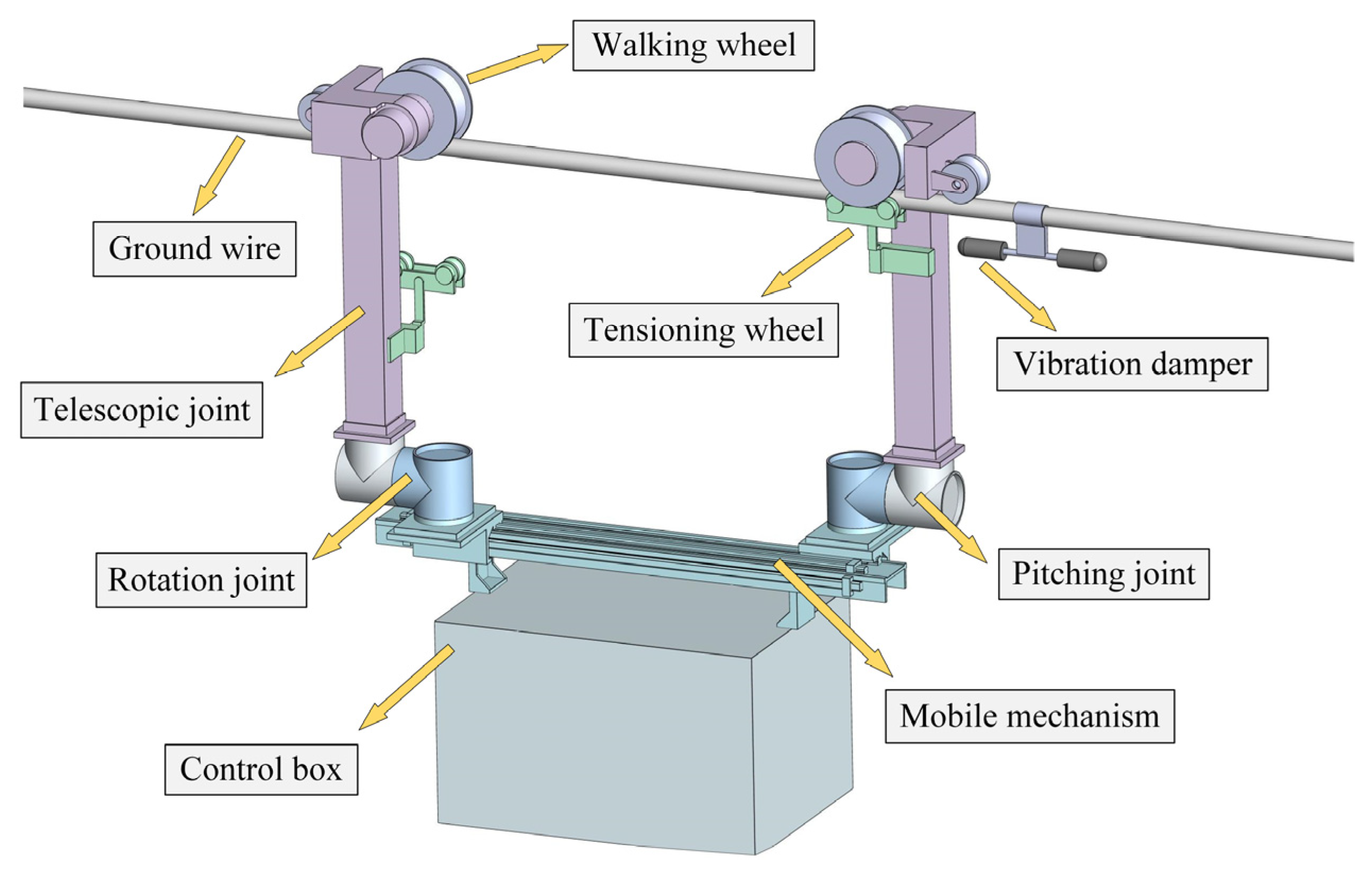
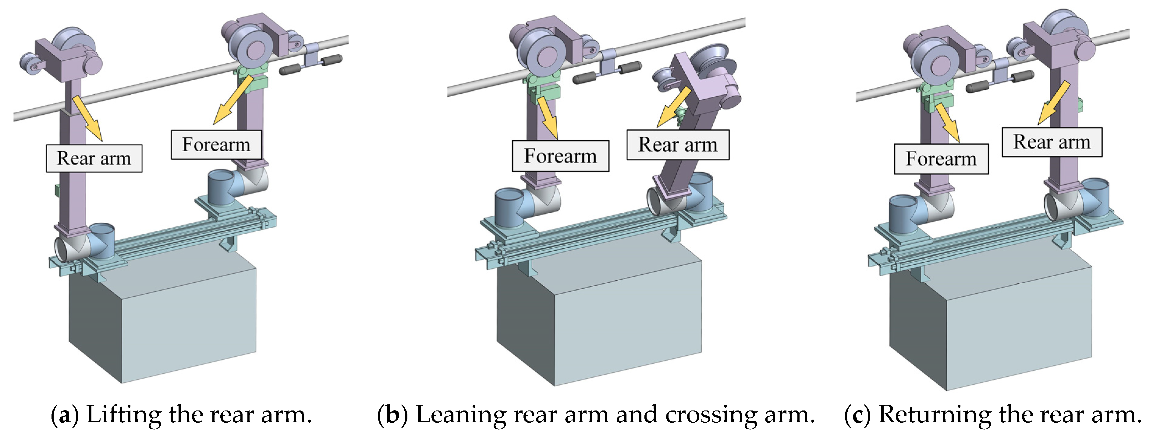
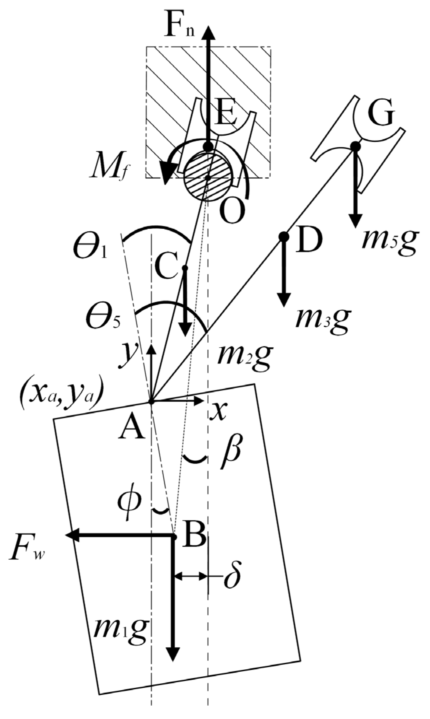
2. Analysis of the Swinging Motion of Inspection Robots around Transmission Lines

Figure 1 shows a physical model of a dual-arm wheeled inspection robot and a schematic diagram of its working environment. From the figure, it is evident that the inspection robot has a central symmetric structure, mainly composed of two walking arms, a mobile mechanism, and a control box. The walking arms consist of functional modules such as walking wheels, tensioning wheels, telescopic joints, pitch joints, and rotation joints.
During maintenance tasks, inspection robots often need to cross over electric power fittings such as vibration dampers and suspension clamps along high-voltage transmission lines. Robots often use a single arm to grip the transmission lines, while the other arm detaches from the transmission lines to traverse obstacles such as power fittings and facilities along the transmission line; the two arms alternate to cross obstacles. Figure 2 shows a schematic diagram illustrating the process of an inspection robot crossing over vibration dampers. The robot moves along a transmission line while using an ultrasonic sensor to continuously measure the distance between obstacles and the walking wheel. When the walking wheel is 10 cm away from the obstacle, the forearm presses the wheel tightly in coordination with the telescopic joint and grips the transmission line. The telescopic joint of the rear arm then lifts the walking wheel, as shown in Figure 2a. The angle of the rear arm’s pitch joint is adjusted, causing the walking wheels on the rear arm to move outward, deviating from the vertical plane of the transmission lines. The mobile mechanism pushes the rear arm forward by crossing the arms, enabling it to overcome obstacles. As shown in Figure 2b, the rear arm’s pitch joint returns to its original position, the telescopic joint lowers to make the rear arm wheel walk back onto the transmission line, the tensioning wheel rises, and the transmission line is clamped, as depicted in Figure 2c. The inspection robot has a symmetrical structure; therefore, the forearm performs the same operation as the rear arm, enabling the robot to cross obstacles with its two walking arms.
While crossing obstacles, the robot is in a single-arm grasping state of the transmission line, and is primarily affected by wind force, gravity, and friction. The modeling of the inspection robot was based on a four-bar linkage model defined elsewhere [26]. A simplified obstacle-crossing model of the robot in the xy plane is shown in Figure 3. The simplified model mainly consists of a control box, two walking arms, and two walking wheels. The intersection point of the two walking arms and the control box is point A. The weight of the control box, forearm, rear arm, forearm walking wheel, and rear arm walking wheel are denoted as m1, m2, m3, m4, and m5, respectively. The centroids are located at points B (assuming the centroid of the control box is at the geometric center), C, D, E, and G. The distances from the centroids to point A are denoted as l1, l2, l3, l4, and l5, respectively. The positions of the centroids of each mechanism, Pi (xci, yci), are shown as follows:
{ x c 1 = x a + l 1 · sin ϕ y c 1 = y a l 1 · cos ϕ x c 2 = x a + l 2 · sin ( θ 1 ϕ ) y c 2 = y a + l 2 · cos ( θ 1 ϕ ) x c 3 = x a + l 3 · sin ( θ 5 ϕ ) y c 3 = y a + l 3 · cos ( θ 5 ϕ ) x c 4 = x a + l 4 · sin ( θ 1 ϕ ) y c 4 = y a + l 4 · cos ( θ 1 ϕ ) x c 5 = x a + l 5 · sin ( θ 5 ϕ ) y c 5 = y a + l 5 · cos ( θ 5 ϕ )
where xa and ya are the coordinates of the connection point between the arm and the control box, ϕ is the tilt angle of the robot body, θ1 is the pitch angle of the forearm joint, and θ5 is the pitch angle of the rear arm joint. The position of the robot’s centroid (xc, yc) is shown as follows:
{ x c = 1 5 m i x c i / 1 5 m i y c = 1 5 m i y c i / 1 5 m i
From Equations (1) and (2), the velocity and acceleration of the robot’s centroid can be obtained as follows:
{ V x = 1 5 m i x ˙ c i / 1 5 m i V y = 1 5 m i y ˙ c i / 1 5 m i
{ A x = 1 5 m i x ¨ c i / 1 5 m i A y = 1 5 m i y ¨ c i / 1 5 m i
From Equation (4), the force exerted on the robot by the transmission line can be obtained as follows:
{ F x = 1 5 m i x ¨ c i F y = 1 5 m i y ¨ c i 1 5 m i g
Let the static friction coefficient between the transmission line and the inspection robot’s walking wheels be μ, and the horizontal wind force acting on the robot be Fw. According to Equation (5), when the horizontal force exerted by the transmission line on the robot is less than or equal to the static friction force (FxμFy), the robot remains stationary. When the horizontal force exceeds the static friction force (Fx > μFy), the robot starts to deviate. When the wind force acting on the robot is less than or equal to the static friction force exerted by the transmission line (FwμFy), the robot’s offset remains unaffected by the wind force. When the wind force exceeds the static friction force (Fw > μFy), the robot’s offset may increase or decrease.

3. Inspection Robot Anti-Sway Control Strategy

When an inspection robot is directly suspended on a transmission line, if a counterweight mechanism is directly added to control the swing, it will increase the weight of the robot and affect its cruising ability. As shown in Figure 3, β represents the swing angle of the inspection robot, and δ represents the distance between the geometric center of the control box and the vertical plane of the transmission lines, referred to as the body offset. The length from point A to point O is denoted as l6, the length from point C to point O is denoted as l7, and the length from point B to point O is denoted as l8. The distances from the centers of gravity C, D, and G to the vertical plane of the transmission lines are denoted as l9, l10, and l11, respectively. Based on trigonometric relationships, the expressions are derived as follows:
{ β = arcsin δ l 8 ϕ = arccos ( l 1 2 + l 8 2 l 6 2 2 × l 1 · l 8 ) - β l 8 = l 1 2 + l 6 2 2 × l 1 · l 6 · cos ( π - θ 1 ) l 9 = l 7 · sin ( θ 1 ϕ ) l 10 = l 3 · sin ( θ 5 ϕ ) l 6 · sin ( θ 1 ϕ ) l 11 = l 5 · sin ( θ 5 ϕ ) l 6 · sin ( θ 1 ϕ )
The frictional torque of the transmission line on the walking wheel is denoted by Mf, with Mfmax representing the maximum frictional torque. MFw represents the torque caused by wind force on the robot. M1, M2, M3, and M5 are the gravitational torques exerted on the robot by the control box, forearm, rear arm, and rear arm walking wheel, respectively. The torque balance equation on the vertical cross-section of the inspection robot’s transmission line is as follows:
M 3 + M 5 + M F w = M f max + M 1 + M 2
Let r be the radius of the transmission line, and fmax be the maximum static friction between the transmission line and the walking wheel. The torque balance equation can be derived for Formula (7) as follows:
m 3 g · l 10 + m 3 g · l 11 + F w · l 8 · cos β = f max · r + m 1 g · δ + m m 2 g · l 9
By combining Formulas (6) and (8), the torque balance equation can be further derived as follows:
m 3 g · ( l 3 · sin ( θ 5 arcos ( l 1 2 + l 8 2 l 6 2 2 × l 1 · l 8 ) + arcsin δ l 8 ) l 6 · sin ( θ 1 arcos ( l 1 2 + l 8 2 l 6 2 2 × l 1 · l 8 ) + arcsin δ l 8 ) ) + m 5 g · ( l 5 · sin ( θ 5 arcos ( l 1 2 + l 8 2 l 6 2 2 × l 1 · l 8 ) + arcsin δ l 8 ) l 6 · sin ( θ 1 arcos ( l 1 2 + l 8 2 l 6 2 2 × l 1 · l 8 ) + arcsin δ l 8 ) ) + F w · l 1 2 + l 6 2 2 × l 1 · l 6 · cos ( π θ 1 ) · cos ( arcsin δ l 8 ) = f max · r + m 1 g · δ + m 2 g · l 7 · sin ( θ 1 arcos ( l 1 2 + l 8 2 l 6 2 2 × l 1 · l 8 ) + arcsin δ l 8 )
The values of l1, l3, l5, l6, l7, m1, m2, m3, m5, and r are measured, with units of meters for l1, l3, l5, l6, l7, and r and kilograms for m1, m2, m3, and m5, as shown in Table 1.
The measured results are plugged into Equation (9) to obtain the torque balance equation as follows:
119 . 56 × ( 0 . 33 sin ( θ 5 arcos ( 0 . 207 cos θ 1 + 0.058 0.34 × 0.401 + 0.207 cos θ 1 ) + arcsin δ 0.401 + 0.207 cos θ 1 ) 0.61 × sin ( θ 1 arcos ( 0 . 207 cos θ 1 + 0.058 0.34 × 0.401 + 0.207 cos θ 1 ) + arcsin δ 0.401 + 0.207 cos θ 1 ) ) + 24.5 × ( 0.68 sin ( θ 5 arcos ( 0 . 207 cos θ 1 + 0.058 0.34 × 0.401 + 0.207 cos θ 1 ) + arcsin δ 0.401 + 0.207 cos θ 1 ) 0.61 × sin ( θ 1 arcos ( 0 . 207 cos θ 1 + 0.058 0.34 × 0.401 + 0.207 cos θ 1 ) + arcsin δ 0.401 + 0.207 cos θ 1 ) ) + F w · 0.401 + 0.207 cos θ 1 · cos ( arcsin δ 0.401 + 0.207 cos θ 1 ) = f max · r + 112.7 δ + 34.957 sin ( θ 1 arcos ( 0 . 207 cos θ 1 + 0.058 0.34 × 0.401 + 0.207 cos θ 1 ) + arcsin δ 0.401 + 0.207 cos θ 1 )
The torque balance equation after simplifying Formula (10) is as follows:
δ = 10 1127 ( 56.115 sin ( θ 5 arcos ( 0 . 207 cos θ 1 + 0.058 0.34 × 0.401 + 0.207 cos θ 1 ) + arcsin δ 0.401 + 0.207 cos θ 1 ) 122.834 sin ( θ 1 arcos ( 0 . 207 cos θ 1 + 0.058 0.34 × 0.401 + 0.207 cos θ 1 ) + arcsin δ 0.401 + 0.207 cos θ 1 ) + F w · 0.401 + 0.207 cos θ 1 · cos ( arcsin δ 0.401 + 0.207 cos θ 1 ) 0.01 f max )
According to Equation (11), the body offset, δ, changes with the variations in the forearm pitch joint angle, θ1, the rear arm pitch joint angle, θ5, the wind force, Fw, and the maximum frictional force, fmax. During the obstacle crossing process, the wind force, Fw, and the maximum frictional force, fmax, are uncontrollable external forces, and the rear arm pitch joint angle, θ5, has been pre-planned. Therefore, it is necessary to adjust the forearm pitch joint angle, θ1, to reduce the fuselage offset, δ.

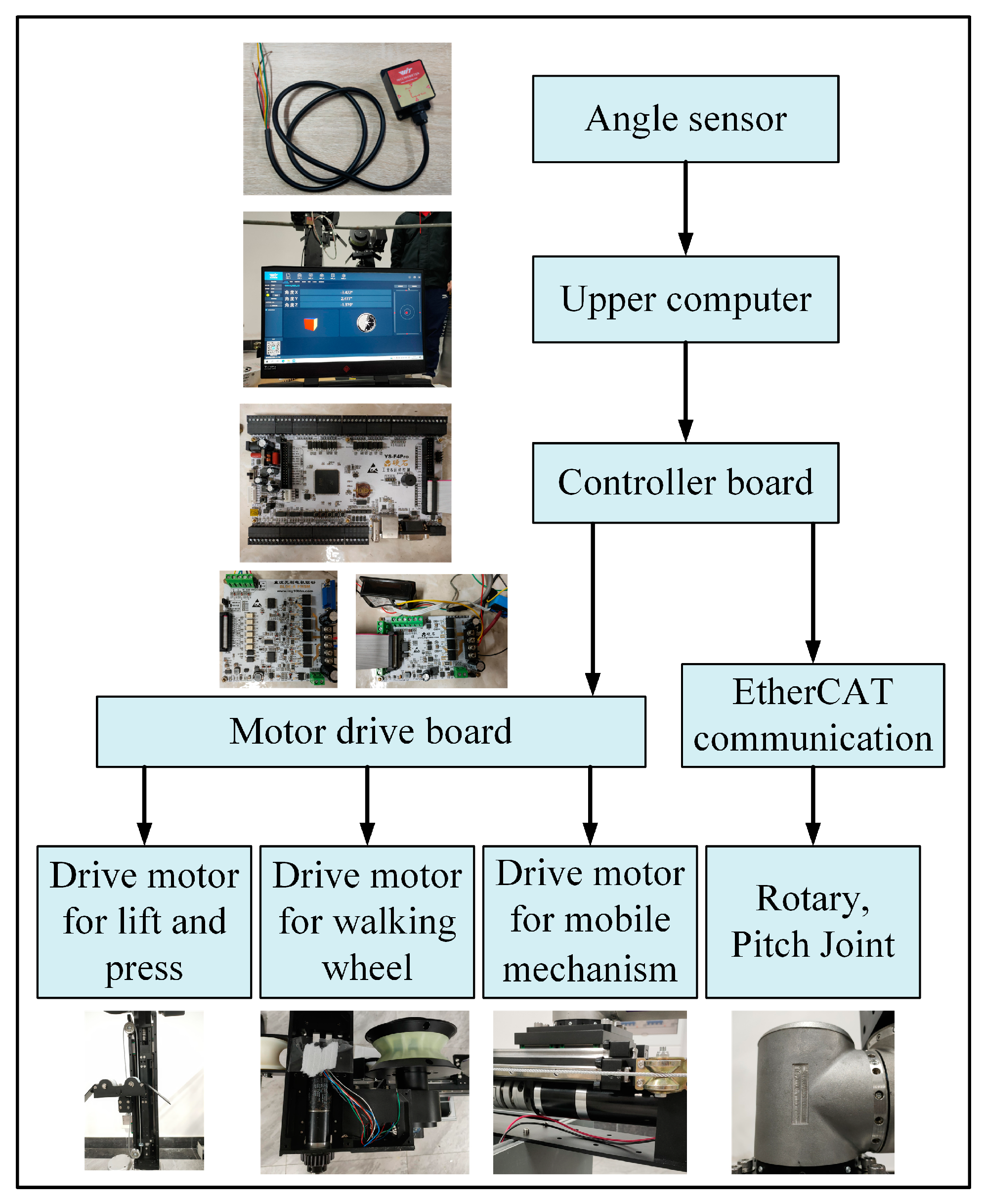
4. Inspection Robot Anti-Swing Control System

4.1. Anti-Swing Fuzzy PID Controller

Analysis of the swing around transmission lines of the inspection robot revealed that the robot’s body offset, δ, varies over time during obstacle crossing. In actual working environments, the coefficient of friction between the wheels of the inspection robot and the surface of the transmission line is variable; therefore, the anti-swing control system becomes a nonlinear time-varying system, making the control of the body offset, δ, relatively difficult. While performing inspection tasks in the air, the robot is vulnerable to the influence of wind forces, causing unpredictable increases or decreases in the swing amplitude of the robot around the transmission line. To manage the body offset, δ, closer to 0, it is required to continually adjust the pitch angle, θ1, of the robot’s forearm joint depending on real-time detection of the body offset, δ, during obstacle crossing.
PID control is a regulation control technique dependent on the present error, cumulative error, and error change rate. PID control can progressively approach the target value of the system output and maintain stability by adjusting the derivative, integral, and proportional factors. However, traditional PID control does not support adaptive parameter adjustment; therefore, it is difficult to satisfy the needs of nonlinear and time-varying control systems because its parameters need to be tuned in relation to existing systems, and the tuned values might only be suitable for certain circumstances of operation. Based on PID control, fuzzy PID control incorporates concepts from fuzzy logic, and introduces fuzzy rules, fuzzy inference, and theory fuzzy set theory into PID control. Fuzzy PID control is more adaptable and robust than traditional PID control since it can handle fuzzy, time-varying, and nonlinear systems. The inspection robot’s anti-sway control system is vulnerable to the impact of wind force; thus, to improve the stability and control accuracy of the anti-sway control system, the fuzzy PID control method is used to control the speed ω(t) of the forearm pitch joint, and then control the angle, θ1, of the forearm pitch joint, aiming to make the robot’s body offset, δ, approach 0. The concept diagram for the robot’s fuzzy PID control with anti-sway is displayed in Figure 4.
As shown in Figure 4, the fuzzy PID controller’s inputs are the body offset, δ, and its rate of variation, and its output is the angular velocity, ω(t), of the forearm pitching joint. In this study, the inspection robot’s procedure of crossing obstacles was simulated by using a virtual prototype system created by Adams. The input value is the angular velocity, ω(t), of the forearm pitching joint, and the output value is the body offset, δ. The fuzzy PID controller will receive negative feedback from the body offset, δ, to dynamically alter the forearm pitching joint’s angular velocity, ω(t), and subsequently control its angle, θ1. Wind force, Fw, was added to the virtual prototype system as an outside disturbance, and the variable speeds of the robot’s various joint movements were added over time during obstacle crossing. The angular velocities of each joint movement were solved through the robot’s kinematic equations based on the predetermined motion trajectory for obstacle crossing; this is not elaborated upon here.

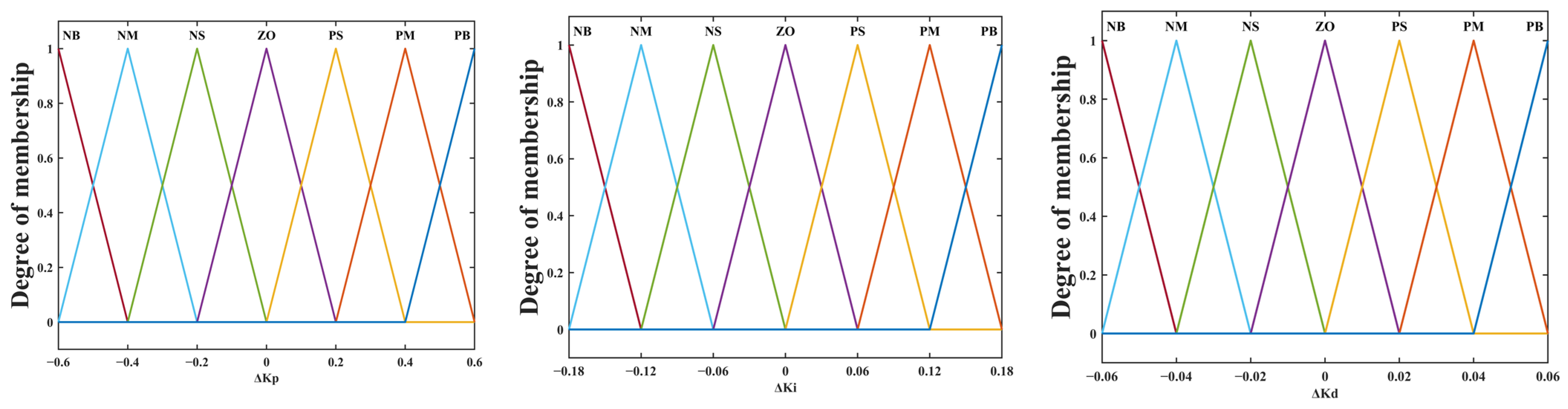
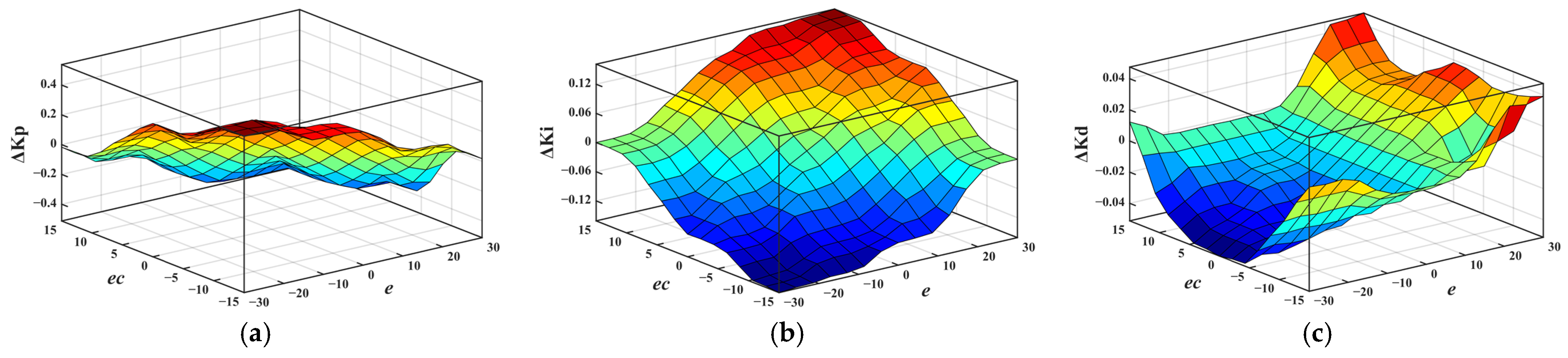
4.2. Design of Anti-Swing Fuzzy PID Controller

The deviation between the feedback body offset, δ(t), and the desired body offset, δ, is defined as the error, e; ec stands for the rate of relative change in error, e, over time; and the fuzzy controller’s input variables are the error, e, and the error rate, ec. The PID controller’s correction factors, ΔKP, ΔKI, and ΔKD, are employed as output variables, with the fuzzy controller in this study configured with seven fuzzy subsets for the five variables of NB, NM, NS, ZO, PS, PM, and PB. The membership functions for the error, e, and the error rate, ec, were chosen using Gaussian functions: the initial value of the body offset, δ, is 0 mm, the error, e, domain and error rate, ec, domain were set to (−30, 30) and (−15, 15), respectively, to minimize the body δ offset during the obstacle crossing procedure. Triangular membership functions were used to select the correction factors ΔKP, ΔKI, and ΔKD. The values for the ΔKP, ΔKI, and ΔKD domains were (−0.6, 0.6), (−0.18, 0.18), and (−0.06, 0.06), respectively. In Figure 5 and Figure 6, the membership functions for the input variables e and ec, and the output variables ΔKP, ΔKI, and ΔKD, are displayed.
According to experimental and empirical parameters, the variables ΔKP, ΔKI, and ΔKD’s fuzzy control rules were set as indicated in Table 2, Table 3 and Table 4. The output surfaces for variables ΔKP, ΔKI, and ΔKD were produced by editing fuzzy rules in MATLAB’s Fuzzy Logic Designer, as shown in Figure 7.
To become exact values, the fuzzy subsets produced by the fuzzy inference engine must undergo a defuzzification process. Common defuzzification methods include the weighted average method, area bisecting method, centroid method, maximum membership degree method, triangular fuzzy number defuzzification method, etc. The system for the inspection robot’s anti-sway control should be able to react precisely to the smaller changes in body offset; the centroid method has a higher accuracy and response speed compared with other methods, and the output value of fuzzy reasoning is smoother. Therefore, this study used the centroid averaging method for defuzzification.

5. Simulation and Experimental Analysis of Anti-Sway Control for Inspection Robots Based on Adams/Simulink

5.1. Building of the Adams/Simulink Simulation Platform

The robot and the transmission line were the two components of the obstacle-crossing model of the inspection robot along the transmission line, which was built on the Adams/Simulink simulation platform. The inspection robot and transmission line models were constructed in SolidWorks. Subsequently, these models were imported into Adams software. Movable links were added to the telescopic joints and rotary links were added to the rotation joints. Fixed links were attached to the tower. Contact forces were implemented to simulate the interaction between the transmission lines and the walking wheels. Velocity data of each joint during the obstacle-crossing process were imported. The CUBSPL function was utilized to incorporate the velocity of each joint into the driver of the corresponding constraint. Figure 8 depicts the obstacle-crossing model of the inspection robot along the transmission line.
A simulation model for both PID control and fuzzy PID control was constructed in the MATLAB/Simulink environment, as depicted in Figure 9. A comparative study was conducted, comparing the PID control simulation model with the fuzzy PID control simulation model. An accurate mathematical model for management of the forearm pitch joint angle is challenging to build since the inspection robot’s anti-sway control system is a nonlinear time-varying system that is vulnerable to external disturbances such as wind force. Consequently, the key proportion approach and the clipping experimental method were combined to adjust the parameters of the inspection robot’s anti-swing control system. The steps are as follows:
  • The key proportion method is used to determine the initial value of the gain coefficient KP. The amplitude and period of the system’s oscillation signal are measured to obtain the critical gain, which is then set as the initial value of the gain coefficient, KP.
  • The initial integration coefficient, KI, and the differentiation coefficient, KD, are calculated based on the oscillation period. KI is approximately equal to one-quarter of the oscillation period, while KD is approximately equal to one-tenth of the oscillation period.
  • The clipping experiment method is used for experimental control. The response curve of the system to a unit step input is observed, and the key response characteristics are measured.
  • Based on the experimental data and response characteristics, further adjustment of the PID parameters is performed by gradually adjusting the proportional coefficient, KP, the integral coefficient, KI, and the derivative coefficient, KD, aiming to make the system response as close as possible to the desired result. Finally, the starting values of the fuzzy PID controller parameters KP, KI, and KD are set to 0.3, 0.072, and 0.0005 accordingly.

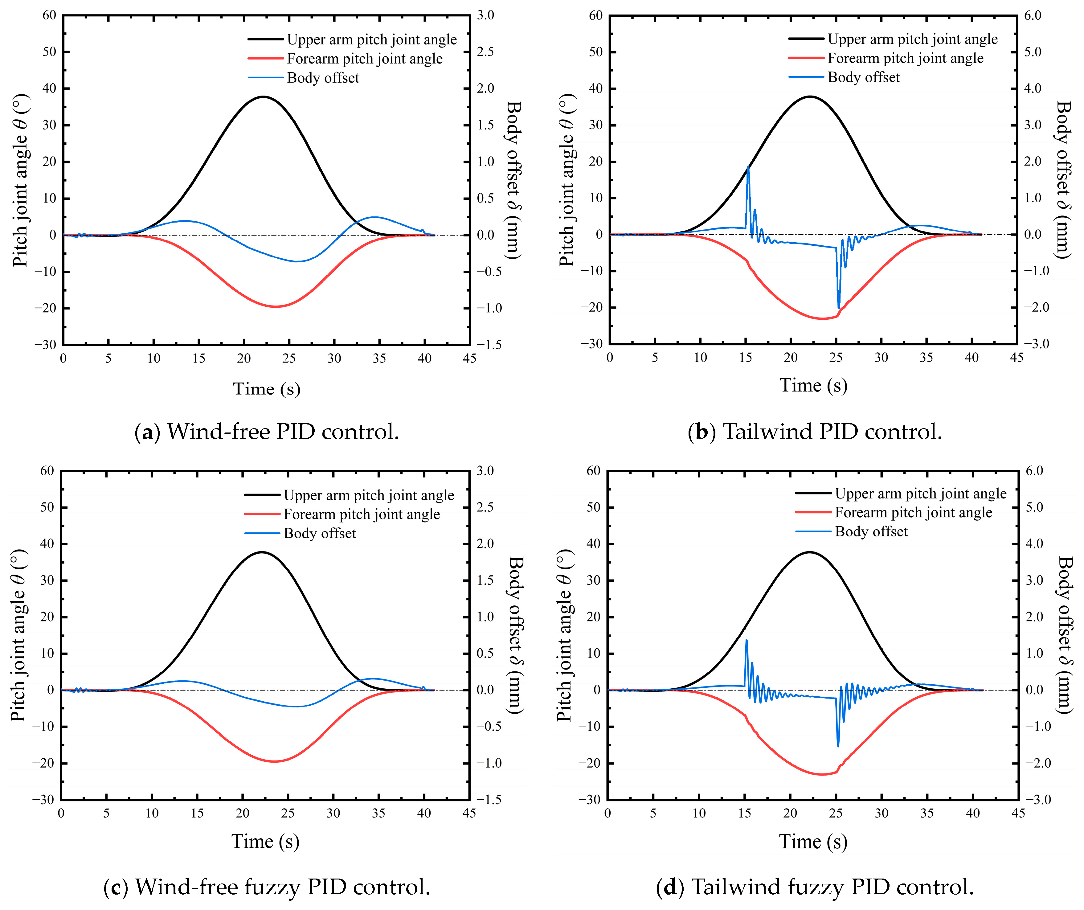
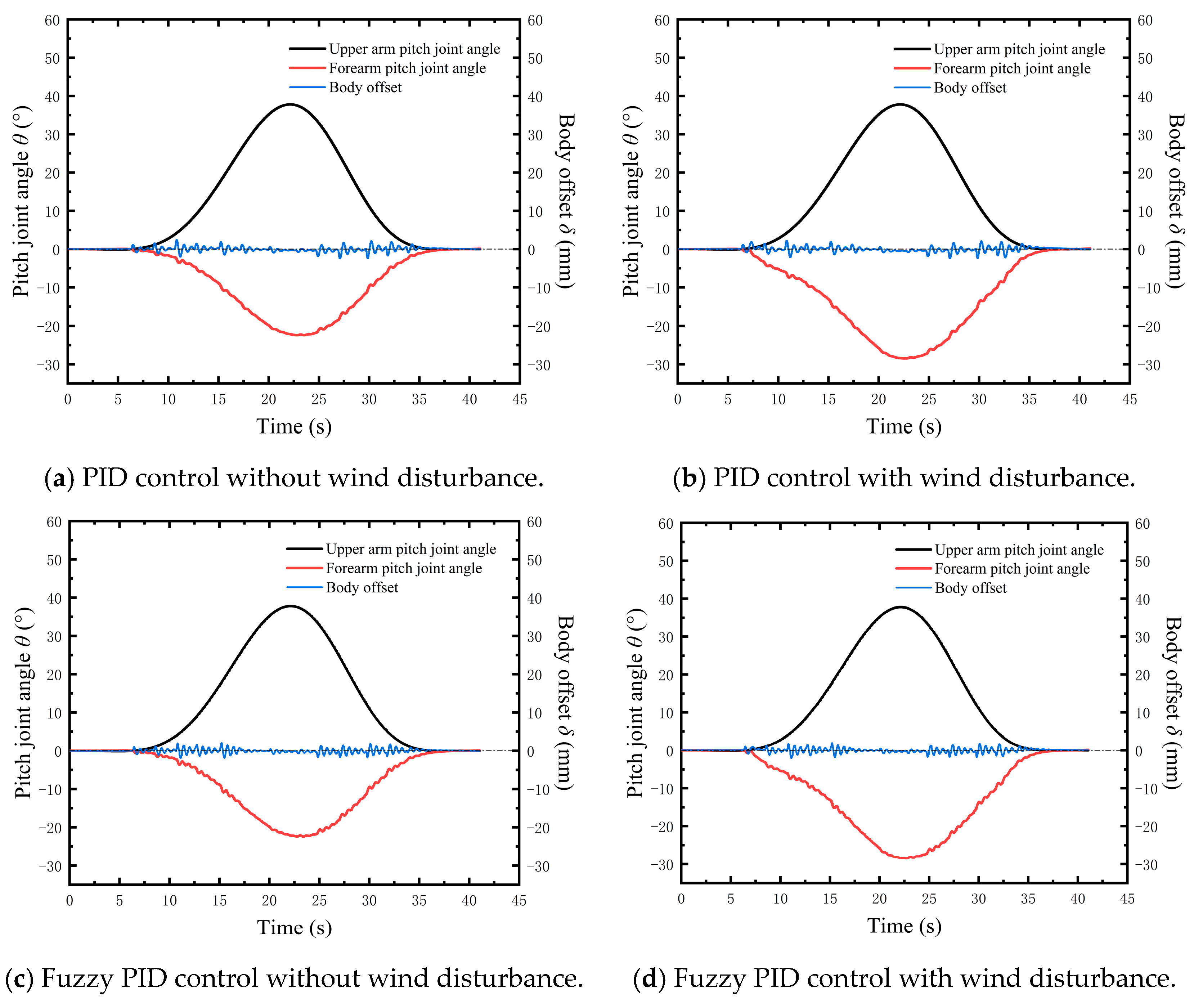
5.2. Simulation Experiments and Analysis

Before conducting actual tests, collaborative simulation experiments utilizing Adams/Simulink were used to confirm the viability of the control system to prevent incidents involving the inspection robot detaching and falling off the transmission line during the obstacle-crossing procedure. In Adams, the obstacle-crossing process time for the inspection robot was set to 41.05 s, with 100 simulation steps. In the fuzzy PID controller, the target body offset, δ, was set to 0 mm. To simulate the influence of wind on the inspection robot during obstacle crossing, simulated wind with a force of 10 N was applied to the inspection robot between 15 s and 25 s. When the body sway direction and the wind force direction coincide, it is called a “tailwind”, and when it is opposite, it is called a “headwind”. The obstacle-crossing experiments were conducted in tailwind, headwind, and calm wind conditions without anti-swing control, and the body offset, δ, was measured under different wind forces. From Figure 10, it can be observed that under wind-free conditions and without anti-swing control, during the obstacle crossing process of the inspection robot, between 5 s and 22 s, as the angle, θ5, of the rear arm pitching joint increased, the body offset, δ, increased. Between 22 s and 35 s, as the angle, θ5, of the rear arm pitching joint decreased, the body offset, δ, decreased. The maximum body offset was 49.31 mm. In the tailwind conditions, the maximum body offset reached 58.51 mm, which is an increase of 18.65% compared with the no-wind experiment. In the headwind conditions, the maximum body offset was 39.92 mm, which is a decrease of 19.04% compared with the no-wind experiment.
Obstacle-crossing experiments were conducted in downwind and no-wind conditions using PID and fuzzy PID control methods; the body offset, δ, and the pitch joint angle, θ1, of the forearm were measured under different control methods. Figure 11 shows the variation curve of the body offset, δ, the pitch joint angle, θ1, of the forearm, and the angle, θ5, of the rear arm pitching joint under anti-swing control.
From Figure 11a,c, it can be observed that in the absence of wind, the range of body offset variation under traditional PID control is −0.36 mm to 0.19 mm, while under fuzzy PID control, the range of body offset variation is −0.22 mm to 0.15 mm. The peak value of body offset is reduced by 99.27% and 99.55%, respectively, compared with the uncontrolled condition. The maximum peak value of the body offset under fuzzy PID control decreased by 38.9% when compared with PID control, according to a comparative analysis of the body offset data under fuzzy PID and PID control. The standard deviation of the body offset change curve under fuzzy PID control is 0.13 mm, which is 31.58% less than the 0.19 mm standard deviation under PID control.
From Figure 11b,d, it can be observed that under the downwind effect, the range of body offset variation under traditional PID control is −2.02 mm to 1.86 mm, while under fuzzy PID control, the range of body offset variation is −1.54 mm to 1.38 mm. The peak values of body offset are reduced by 96.55% and 97.37%, respectively, compared with the uncontrolled conditions. The maximum peak value of the body offset under fuzzy PID control decreased by 23.8% when compared with PID control, according to a comparative analysis of the body offset data under fuzzy PID and PID control. The standard deviation of the body offset change curve under fuzzy PID control is 0.22 mm, which is 33.33% less than the 0.33 mm standard deviation under PID control. After introducing wind disturbance to the system, the body offset fluctuates when wind appears and disappears. The waveform oscillates because of the real-time modification of the proportional, integral, and derivative parameters by fuzzy PID control. However, in contrast to conventional PID control, it is closer to the intended value because of the lower oscillations and faster response time to external disturbances.

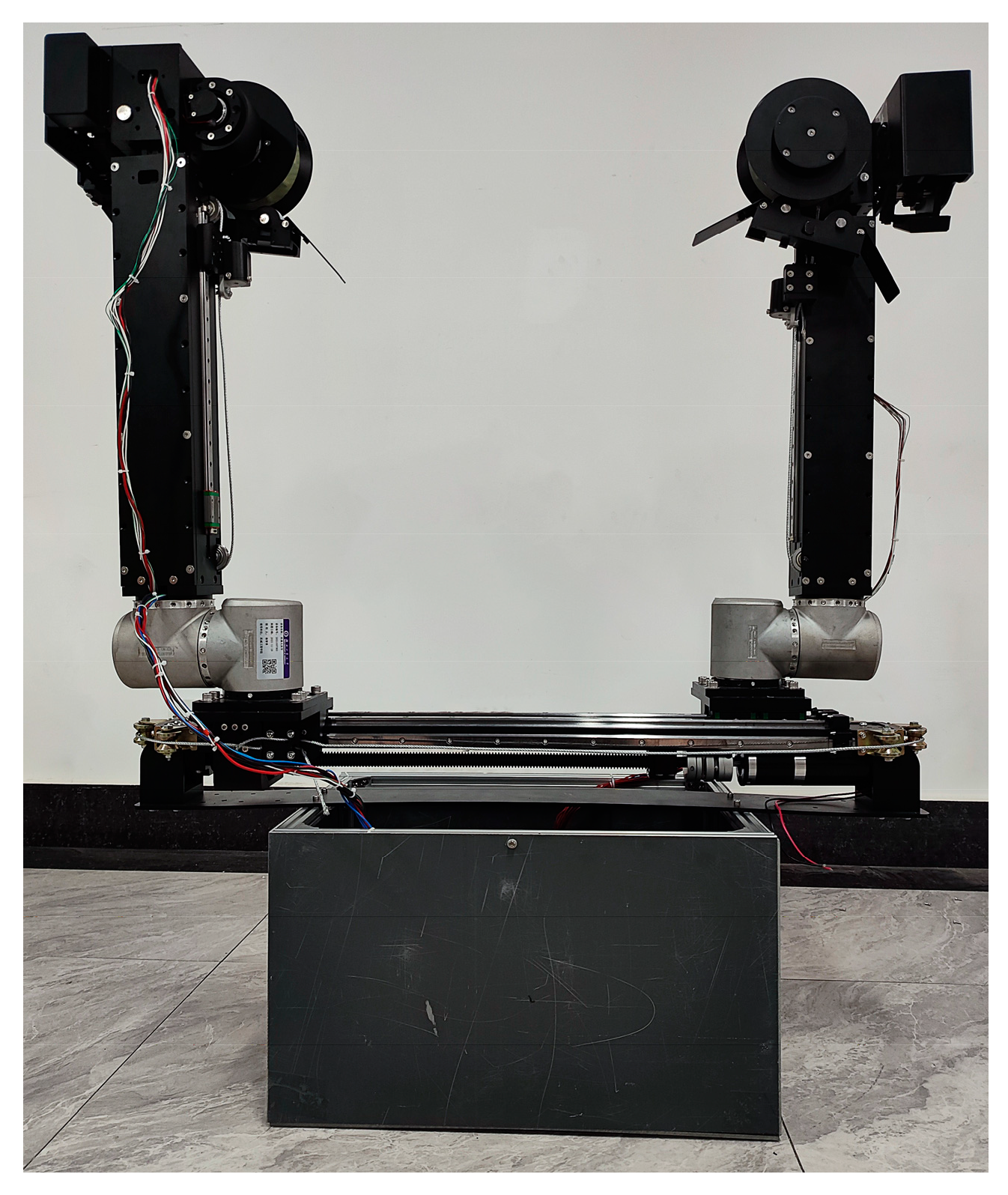
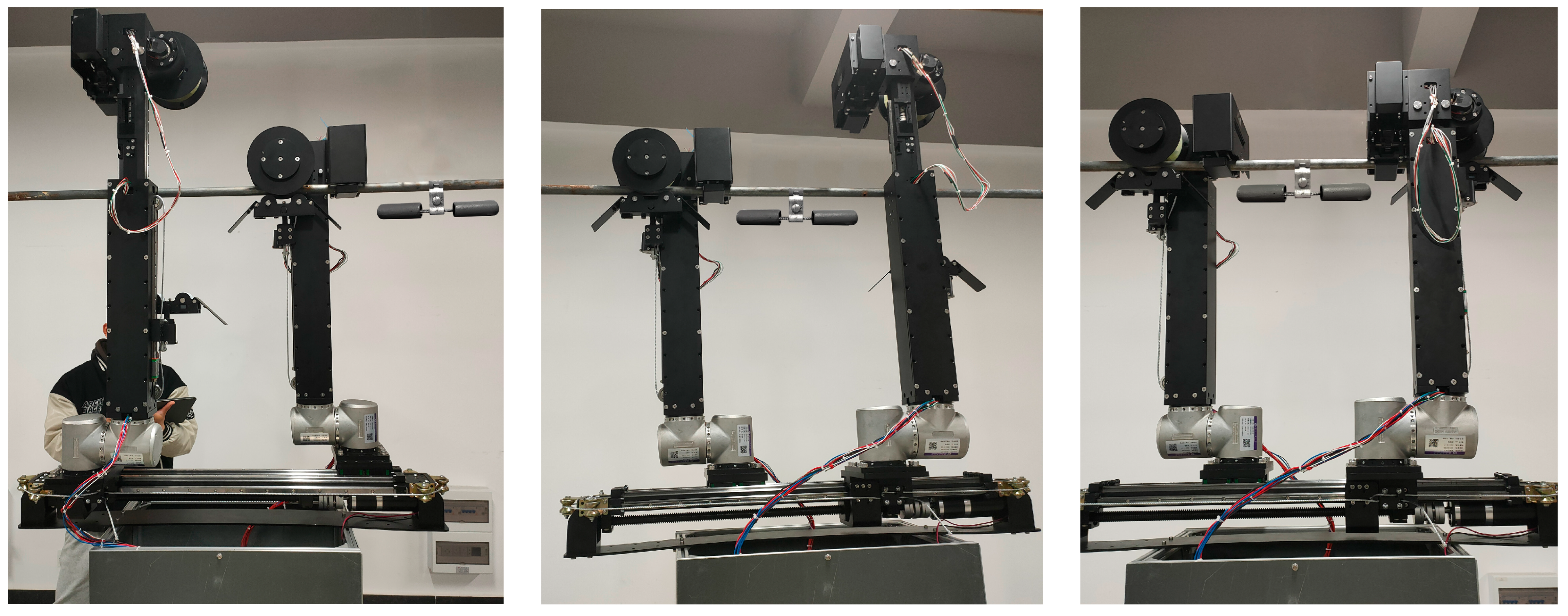
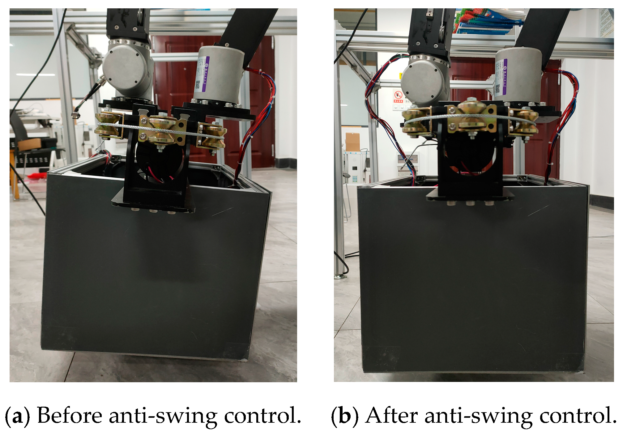
5.3. Prototype Experiment and Analysis

Figure 12 shows a prototype of the inspection robot; the overall dimensions of the robot were 80 × 35 × 110 cm, with a total weight of 43 kg. To ensure the safety of the prototype and the experimental personnel, a simulation high-voltage power transmission line was built in the laboratory. The inspection robot’s experimental schematic for crossing obstacles along the transmission line is displayed in Figure 13. The flowchart of the inspection robot control system is depicted in Figure 14; the angle sensor was used to continuously collect swing angle, β, data of the inspection robot and transmit them to the upper computer. Based on trigonometric relationships, the upper computer calculated the body offset, δ, which was then used as an input for the fuzzy PID controller. The output of the fuzzy PID controller was then passed on to the control board. The control board utilized the output from the fuzzy PID controller to control the pitch angle, θ1, of the forearm joint, aiming to prevent swing deviation.
To simulate the wind disturbance experienced by the inspection robot during obstacle crossing, wind devices were placed beside the obstacle-crossing route. The wind blown by wind turbines formed a fan-shaped pattern, with the maximum wind speed, V, reaching about 10 m per second when directly facing the turbines, and decreasing towards the sides. The control box was primarily acted upon by the wind force, with an effective area, A, of approximately 0.168 m2. Assuming an air density, ρ, of 1.225 kg/m3, according to the wind force formula (Equation (12)), the wind force, F, acting on the control box was calculated to be approximately 10.29 N.
F = 0.5 ρ · A · V 2
The obstacle-crossing experiment with the inspection robot was conducted without anti-swing control, both under the conditions of no wind and under the influence of wind devices. The body offset, δ, was measured. Figure 15 shows the variation curve of the deviation of the body offset, δ, and the angle, θ5, of the rear arm pitching joint without anti-swing control. Based on Figure 15, it can be observed that without anti-swing control and in the absence of wind force, the maximum body offset of the inspection robot during obstacle crossing was 57.13 mm. With the wind devices in effect, the maximum body offset reached 74.90 mm, which is an increase of 31.10% compared with the scenario without wind.
Obstacle crossing studies were carried out using PID control and fuzzy PID control under the effects of both wind devices and no wind situations. The experiments measured the body offset, δ, and the angle of the forearm’s pitch joint, θ1, under different control conditions. Figure 16 shows the variation curve of the body offset, δ, the pitch joint angle, θ1, of the forearm, and the angle, θ5, of the rear arm pitching joint under anti-swing control. Figure 17 presents the body offset before and after anti-swing control of the inspection robot.
Based on the data from Figure 16a,c, it can be observed that in the absence of wind, the range of body offset under traditional PID control was −2.44 mm to 2.40 mm, and under fuzzy PID control it was −1.96 mm to 1.98 mm. Compared with no control, the peak values of body offset were reduced by 95.73% and 96.53%, respectively. The maximum peak value of the body offset under fuzzy PID control decreased by 18.85% when compared with PID control, according to a comparative analysis of the body offset data under fuzzy PID and PID control. The standard deviation of the body offset change curve under fuzzy PID control was 0.58 mm, which is 6.45% less than the 0.62 mm standard deviation under PID control.
Based on Figure 16b,d, it can be observed that under the influence of wind devices, the range of body offset under traditional PID control was −2.39 mm to 3.06 mm, and under fuzzy PID control it was −2.04 mm to 2.23 mm. Compared with no control, the peak values of body offset were reduced by 95.87% and 97.02%, respectively. The maximum peak value of the body offset under fuzzy PID control decreased by 27.12% when compared with PID control, according to a comparative analysis of the body offset data under fuzzy PID and PID control. The standard deviation of the body offset change curve under fuzzy PID control was 0.61 mm, which is 7.57% less than the 0.66 mm standard deviation under PID control.
Comparing Figure 12 and Figure 16 under no wind disturbance, it can be observed that the body offset curve under simulation conditions was relatively smooth, while the body offset curve during the obstacle-avoiding process of the robot exhibited more pronounced fluctuations. Analysis revealed that the friction coefficient between the surface of the transmission lines in the real environment and the inspection robot’s pressing wheel was not constant, which caused variations in static friction torque. Therefore, the robot exhibited shaking during the obstacle-avoiding process.
From the simulation experiments and real machine experiments, it can be concluded that the fuzzy PID anti-swing controller designed in this study can effectively prevent swinging phenomena of inspection robots around transmission lines, thereby enhancing the stability and safety of obstacle-crossing actions. Moreover, this controller can dynamically adjust the PID parameters in real time, which improves the performance and disturbance rejection capability compared with traditional PID control when dealing with the nonlinear time-varying system of inspection robots.

6. Conclusions

(1)
This paper focuses on the situation where a robot’s body sways around transmission lines during the obstacle-crossing process, and analyzes the causes of swaying torque and its impact on robot stability the while crossing obstacles.
(2)
An anti-swing control strategy is proposed by adjusting the pitch angle of the forearm to reduce offset of the robot’s body towards zero and utilizes the fuzzy PID algorithm to achieve adaptive intelligent control for preventing sway in the robot.
(3)
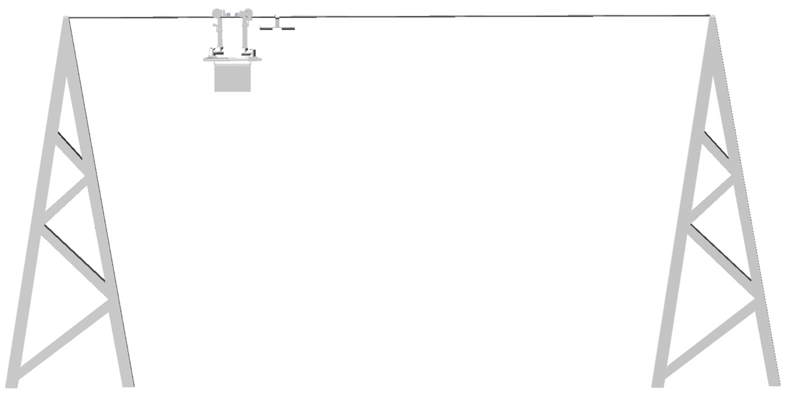
An obstacle-crossing experiment was set up under both windless and wind devices conditions. In both experimental environments, the proposed sway control method kept the robot offset within 3 mm, validating the effectiveness of this approach.

Author Contributions

Conceptualization, Z.Y.; methodology, Z.Y.; software, K.Y.; validation, K.Y. and Y.Y.; formal analysis, K.Y. and Y.Y.; investigation, Z.Z. and H.D; resources, H.D.; data curation, X.L. and S.F.; writing—original draft preparation, K.Y.; writing—review and editing, K.Y.; visualization, K.Y.; supervision, Y.L. and D.Z.; project administration, Y.L. and D.Z.; funding acquisition, Y.L. and D.Z. All authors have read and agreed to the published version of the manuscript.

Funding

This work has been supported by the following funds: Hubei Provincial Science and Technology Innovative Talent Program Project, 2023DJC092. Hubei Provincial Department of Education Key Project, D20221404. Open Fund of Hunan Provincial Key Laboratory of Intelligent Electricity-Based Operation Technology and Equipment (Robot): 2022KZD1001. National Natural Science Foundation of China, 51907055. Hubei Provincial Natural Science Foundation Innovation Group Project, 2023AFA037. National Natural Science Foundation of China, 52075152. China Construction West Construction Science and Technology Research and Development Project, ZJXJZN-2022-03. China State Construction Engineering Corporation 2022 Annual Science and Technology Research and Development Project, CSCEC-2022-Q-52.

Data Availability Statement

Data are contained within the article.

Conflicts of Interest

The author Yu Yan was employed by the company State Grid Hunan Ultra High Voltage Substation. All authors declare that the research was conducted in the absence of any commercial or financial relationships that could be construed as a potential conflict of interest.

References

  1. Alhassan, A.B.; Zhang, X.; Shen, H.; Xu, H. Power transmission line inspection robots: A review, trends and challenges for future research. Int. J. Electr. Power Energy Syst. 2020, 118, 105862. [Google Scholar] [CrossRef]
  2. Gonçalves, S.R.; Carvalho, M.C.J. Review and Latest Trends in Mobile Robots Used on Power Transmission Lines. Int. J. Adv. Robot. Syst. 2013, 10, 108. [Google Scholar] [CrossRef]
  3. Liu, J.; Wu, G.; Fan, F.; Li, Y. A Robot Hybrid Hierarchical Network for Sensing Environmental Variables of a Smart Grid. Sensors 2020, 20, 5521. [Google Scholar] [CrossRef] [PubMed]
  4. Ni, J.; Zhan, T. Smart Sensor Network Optimization and Line Defect Identification Based on UAV Transmission Inspection under 5G Technology. J. Sens. 2022, 2022, 6801985. [Google Scholar] [CrossRef]
  5. Yue, X.; Wang, H.; Feng, Y.; Tian, Y.; Wang, W. Improving Stability of Line Inspection Robot During Crossing Jumper Lines with a Centroid Adjustment Adjusting Mechanism. IEEE Access 2022, 10, 134571–134579. [Google Scholar] [CrossRef]
  6. Wu, H.; Wu, Y.X.; Meng, L.Z.; Liu, C.A.; Yang, G.T. Hybrid velocity switching and fuzzy logic control scheme for cable tunnel inspection robot. J. Intell. Fuzzy Syst. 2015, 29, 2619–2627. [Google Scholar] [CrossRef]
  7. Wang, S.; Jin, G.; Li, J.; Ren, Z.; Chen, H.; Sun, Y. Active damping methods to suppress the payload swing by a 3-degree of freedom cable-driven parallel robot. Asian J. Control 2023, 25, 4796–4812. [Google Scholar] [CrossRef]
  8. Jiang, W.; Wu, G.; Fan, F.; Yan, Y.; Liu, X.; Li, H.; Chen, W. Structure singular value theory based robust motion control of live maintenance robot with reconfigurable terminal function for high voltage transmission line. Int. J. Adv. Robot. Syst. 2018, 15, 17. [Google Scholar] [CrossRef]
  9. Jiang, W.; Yan, Y.; Li, Q.M.; Zhang, A.; Li, H.J.; Jiang, D. Research on robust stabilization control of high-voltage power maintenance robot under wind load action. Ind. Robot-Int. J. Robot. Res. Appl. 2019, 46, 870–881. [Google Scholar] [CrossRef]
  10. Lima, E.J.; Bomfim, M.H.S.; Mourao, M.a.D. POLIBOT—POwer Lines Inspection RoBOT. Ind. Robot Int. J. Robot. Res. Appl. 2018, 45, 98–109. [Google Scholar] [CrossRef]
  11. Xu, B.; Wang, X.; Zhu, Y.; Chen, H. Design of obstacle crossing mechanism of high-voltage transmission line inspection robot. In Proceedings of the 2015 IEEE International Conference on Robotics and Biomimetics (ROBIO), Zhuhai, China, 6–9 December 2015. [Google Scholar]
  12. Gonçalves, R.S.; Carvalho, J.C.M. A mobile robot to be applied in high-voltage power lines. J. Braz. Soc. Mech. Sci. Eng. 2015, 37, 349–359. [Google Scholar] [CrossRef]
  13. Johan, K.J.; Kjeld, M.E.; Rygaard, M.H. Anti-swing control of a hydraulic loader crane with a hanging load. Mechatronics 2021, 77, 102599. [Google Scholar]
  14. Yu, W.; Li, X.; Panuncio, F. Stable Neural Pid Anti-Swing Control for An Overhead Crane. Intell. Autom. Soft Comput. 2014, 20, 13895837. [Google Scholar] [CrossRef]
  15. Chen, H.; Liu, G.; Tian, G.; Zhang, J.; Ji, Z. Safe distance prediction for braking control of bridge cranes considering anti-swing. Int. J. Intell. Syst. 2021, 37, 4845–4863. [Google Scholar] [CrossRef]
  16. Li, X.; Yu, W. Anti-Swing Control for An Overhead Crane with Fuzzy Compensation. Intell. Autom. Soft Comput. 2012, 18, 1–11. [Google Scholar] [CrossRef]
  17. Gu, X.; Xu, W. Moving sliding mode controller for overhead cranes suffering from matched and unmatched disturbances. Trans. Inst. Meas. Control 2020, 44, 60–75. [Google Scholar] [CrossRef]
  18. Wang, J.; Liu, K.; Wang, S.; Chen, H.; Sun, Y.; Niu, A.; Li, H. Dynamic Analysis and Experiment of Underactuated Double-Pendulum Anti-Swing Device for Ship-Mounted Jib Cranes. Pol. Marit. Res. 2022, 29, 145–154. [Google Scholar] [CrossRef]
  19. Sun, M.; Ji, C.; Luan, T.; Wang, N. LQR Pendulation Reduction Control of Ship-Mounted Crane Based on Improved Grey Wolf Optimization Algorithm. Int. J. Precis. Eng. Manuf. 2023, 24, 395–407. [Google Scholar] [CrossRef]
  20. Li, G.; Ma, X.; Li, Z.; Li, Y. Time-Polynomial-Based Optimal Trajectory Planning for Double-Pendulum Tower Crane with Full-State Constraints and Obstacle Avoidance. IEEE-ASME Trans. Mechatron. 2023, 28, 919–932. [Google Scholar] [CrossRef]
  21. Guerrero-Sánchez, M.E.; Lozano, R.; Castillo, P.; Hernández-González, O.; García-Beltrán, C.D.; Valencia-Palomo, G. Nonlinear Control Strategies for a UAV Carrying a Load with Swing Attenuation. Appl. Math. Model. 2020, 91, 709–722. [Google Scholar] [CrossRef]
  22. Zhang, D.; Yang, Y.; Han, H.; Hu, Y. Binocular visual pendulum angle detection and anti-swing control of quadrotor suspension system. Trans. Inst. Meas. Control 2023, 45, 723–735. [Google Scholar] [CrossRef]
  23. Omar, H.M. Hardware-In-the-Loop Simulation of Time-Delayed Anti-Swing Controller for Quadrotor with Suspended Load. Appl. Sci. 2022 12, 1706. [CrossRef]
  24. Shi, D.; Wu, Z.; Chou, W. Harmonic Extended State Observer Based Anti-Swing Attitude Control for Quadrotor with Slung Load. Electronics 2018, 7, 83. [Google Scholar] [CrossRef]
  25. Yang, Y.; Zhang, D.; Xi, H.; Zhang, G. Anti-swing control and trajectory planning of quadrotor suspended payload system with variable length cable. Asian J. Control 2021, 24, 2424–2436. [Google Scholar] [CrossRef]
  26. Zhang, J.; Song, G.; Li, Y.; Qiao, G.; Song, A.; Wang, A. A bio-inspired jumping robot: Modeling, simulation, design, and experimental results. Mechatronics 2013, 23, 1123–1140. [Google Scholar] [CrossRef]
Figure 1. Diagram of an inspection robot model and its working environment.
Actuators 12 00472 g001
Figure 2. Schematic diagram of obstacle crossing by inspection robot.
Actuators 12 00472 g002
Figure 3. Obstacle-crossing model for inspection robots.
Actuators 12 00472 g003
Figure 4. Concept diagram of anti-sway fuzzy PID control.
Actuators 12 00472 g004
Figure 5. The membership functions for the input variables e and ec.
Actuators 12 00472 g005
Figure 6. The membership functions for the output variables ΔKP, ΔKI, and ΔKD.
Actuators 12 00472 g006
Figure 7. Surface of variation in fuzzy PID controller parameters. (a) ΔKP, (b) ΔKI, (c) ΔKD.
Actuators 12 00472 g007
Figure 8. The obstacle-crossing model of the inspection robot along the transmission line.
Actuators 12 00472 g008
Figure 9. Comparative simulation models of the PID control and fuzzy PID control.
Actuators 12 00472 g009
Figure 10. The curve graphs of θ5 and δ without anti-swing control.
Actuators 12 00472 g010
Figure 11. Curve graphs of δ, θ1, and θ5 under PID control and fuzzy PID control.
Actuators 12 00472 g011
Figure 12. Prototype inspection robot.
Actuators 12 00472 g012
Figure 13. Experimental schematic of the inspection robot crossing obstacles along the transmission line.
Actuators 12 00472 g013
Figure 14. The flowchart of the inspection robot control system.
Actuators 12 00472 g014
Figure 15. The curve graphs of θ5 and δ without anti-swing control.
Actuators 12 00472 g015
Figure 16. The curve graphs of δ, θ1, and θ5 under PID control and fuzzy PID control.
Actuators 12 00472 g016
Figure 17. The body offset before and after anti-swing control in an inspection robot.
Actuators 12 00472 g017
Table 1. The lengths and masses of the various components of the inspection robot.
l1l3l5l6l7rm1m2m3m5
0.170.330.680.610.290.0111.512.312.22.5
Table 2. Fuzzy control rule table for ΔKP.
ec
NBNMNSZOPSPMPB
eNBPBPBPMPMPSZOZO
NMPBPBPMPSPSZONS
NSPMPMPMPSZONSNS
ZOPMPMPSZONSNMNM
PSPSPSZONSNSNMNM
PMPSZONSNMNMNMNB
PBZOZONMNMNMNBNB
Table 3. Fuzzy control rule table for ΔKI.
ec
NBNMNSZOPSPMPB
eNBNBNBNMNMNSZOZO
NMNBNBNMNSNSZOZO
NSNBNMNSNSZOPSPS
ZONMNMNSZOPSPMPM
PSNMNSZOZOPSPMPB
PMZOZOPSPSPMPBPB
PBZOZOPSPMPMPBPB
Table 4. Fuzzy control rule table for ΔKD.
ec
NBNMNSZOPSPMPB
eNBPBPBPMPMPSZOZO
NMPBPBPMPSPSZONS
NSPMPMPMPSZONSNS
ZOPMPMPSZONSNMNM
PSPSPSZONSNSNMNM
PMPSZONSNMNMNMNB
PBZOZONMNMNMNBNB
Disclaimer/Publisher’s Note: The statements, opinions and data contained in all publications are solely those of the individual author(s) and contributor(s) and not of MDPI and/or the editor(s). MDPI and/or the editor(s) disclaim responsibility for any injury to people or property resulting from any ideas, methods, instructions or products referred to in the content.

