Article

Learning Pose Dynamical System for Contact Tasks under Human Interaction

School of Power and Mechanical Engineering, Wuhan University, Wuhan 430072, China
*
Authors to whom correspondence should be addressed.
Actuators 2023, 12(4), 179; https://doi.org/10.3390/act12040179
Submission received: 8 March 2023 / Revised: 14 April 2023 / Accepted: 18 April 2023 / Published: 20 April 2023
(This article belongs to the Special Issue Advanced Technologies and Applications in Robotics)

Abstract

:
Robots are expected to execute various operation tasks like a human by learning human working skills, especially for complex contact tasks. Increasing demands for human–robot interaction during task execution makes robot motion planning and control a considerable challenge, not only to reproduce demonstration motion and force in the contact space but also to resume working after interacting with a human without re-planning motion. In this article, we propose a novel framework based on a time-invariant dynamical system (DS), taking into account both human skills transfer and human–robot interaction. In the proposed framework, the human demonstration trajectory was modeled by the pose diffeomorphic DS to achieve online motion planning. Furthermore, the motion of the DS was modified by admittance control to satisfy different demands. We evaluated the method with a UR5e robot in the contact task of the composite woven layup. The experimental results show that our approach can effectively reproduce the trajectory and force learned from human demonstration, allow human–robot interaction safely during the task, and control the robot to return to work automatically after human interaction.

1. Introduction

The rapid development of intelligent robots is making it possible to liberate humans from various physical operations, ranging from industrial manufacturing to our daily life. There are lots of repetitive contact tasks, such as polishing [1], laying up [2], and wiping [3], where people are being gradually replaced by robots. Due to the fact that accurate mathematics models are hard to develop directly for motion and force control, learning a behavior policy from human skills is a promising methodology for robot motion planning for complex contact tasks. During the robot operation, if an operator would like to examine the working quality or repair an imperfection, the operator needs to interact with the robot by dragging the robot. The robot may be released in an arbitrary pose in the free space or contact space after the interaction. However, traditional methods need to plan a new trajectory, which achieves the robot returning back to its previous pose to restart work. This discontinuous operation will reduce the working efficiency significantly. Therefore, a unified framework of motion planning and controlling is required to achieve state transitions automatically for the contact task under human interaction.
Robot learning from human demonstration is a widely accepted method for transferring human skills to a robot. Visual teaching [4], teleoperated teaching [5], and kinesthetic teaching [6] are common demonstration methods. Kinesthetic teaching allows a human to manually guide the robot and is commonly applied in contact tasks, such as peg-in-hole [7], polishing [1], engraving [8], wood planing [9], and so on. The force and trajectory are collected during the demonstration. After acquiring the demonstration trajectory, a motion model is established for the robot to reproduce the motion of human demonstration. Schematically, the art trajectory-level models can be separated into two major methods: statistical machine learning methods and dynamical systems. With the statistical estimation approach, the demonstration trajectory is taken as a random process, and a mathematical model is established between time and trajectory, such as Gaussian Mixture Regression models (GMM) [10], Hidden Markov models (HMM) [11], and so on. The endpoint of the demonstration trajectory is encoded as a stable attractor by a dynamical system (DS), which has been utilized recently as a flexible method to represent the human demonstration. Dynamic Movement Primitives (DMP) [12] is a typically and widely used approach of the DS. DMP is implicitly time-dependent and requires heuristics to reset the phase variable in the face of temporal perturbations [13]. When robot motion is over one dimension, DMP learns a model for each dimension, separately. There are also some modified methods based on DMP, such as probabilistic Movement Primitives (ProMP) [14], Kernelized Movement Primitives (KMP) [15], and Via-Point Movement Primitives (VMP) [16].
To ensure adaptation to perturbation and a dynamically changing environment, it is necessary to develop the time-invariant DS. The stable estimator of DS (SEDS) [13] is one of the time-invariant dynamical systems for learning from demonstration. Then,  τ -SEDS [17] was proposed to solve the problem of a trade-off between stability and accuracy in SEDS. To establish a DS faster, ref. [18] adopted a new diffeomorphic matching to transform the demonstration trajectory into latent space to obtain a simple trajectory, and established a global asymptotically stable DS. Those DS approaches mostly only consider modeling the position information but ignore orientation information. Ref. [19] established both position and orientation dynamical systems with DMP in each dimension. Ref. [20] established the DMP model based on dual quaternion, which describes the translational and rotational motion in a unified manner. In our previous work [21], the pose diffeomorphic DS was proposed to model the pose of the demonstration trajectory based on diffeomorphic matching between the latent and real spaces.
The approaches of modeling human demonstration can be directly used in free space to execute tasks such as picking up or placing objects [22] through extracting the skills from the demonstration trajectory [23,24]. In contrast, obtaining the required contact force by controlling the motion of the robot is always primary for the contact task. With the advantages of DS, it can be extended to the motion planning of continuous contact tasks. Ref. [25] transformed the skill of composite layup using teleoperation and encoded it with DMP. They focused on motion reproduction without the force tracking. If the force modulation is added to the dynamical system, the demonstration force can be also reproduced [26]. Ref. [27] introduced DMP into a hybrid trajectory and force learning frame to realize the learning of a specific class of complex contact-rich insertion tasks. For the continuing contact task, force tracking is needed in the whole process of the task execution. Ref. [28] adopted two groups of DMPs, respectively modeling the trajectory and force, which were combined with the hybrid force/motion control to adjust the motion and provided enough contact force to complete the cleaning operation. Ref. [29] combined DMP with admittance control to obtain the desired force and maintain the stability of the system through an energy tank polishing task. Further, they combined DMP with iterative learning control (ILC) to obtain the expected force using several iterations [30]. It should be noted that the mentioned approaches apply DMP with force control modulation under an ideal environment without any interaction from the human. If an interaction occurs during the task execution, it is significant for the motion planning to satisfy both the human–robot interaction and the pose of the robot resuming work. Ref. [19] encoded both the demonstration trajectory and z-direction force using the DMP model, and controlled the robot reproduction demonstration with a Cartesian impedance controller. If the robot motion was transiently stopped and slightly altered in the motion planning of DMP, the temporal coupling term in the canonical system was changed to delay or restart execution [19]. If the operator tries moving the robot away from the work platform, it will generate a large pose error. Ref. [31] designed the impedance controller frame with various velocity sources. In the case of an interaction wherein velocity sources are switched off, the human can interact with the robot in force/torque mode. When the motion is modeled by the time-invariant DS, the robot would resume working automatically by online motion planning after human interaction. Refs. [3,32] used the time-invariant DS of position to plan the robot polishing trajectory and track constant force based on impedance control with force correction calculated by Gaussian Radial Basis kernel functions. In [3,32], the process of obtaining force correction was found to be complex compared with the force control in [31]. In [3,32], the orientation was obtained through support vector regression to estimate the normal distance and vector to the surface, which needs to be combined with a motion capture system. Meanwhile, in [3,25,31], the methods of force control were based on the impedance control scheme, which limits the application of the methods for the position-controlled robot [33].
Considering the aforementioned issues, a novel framework for learning contact skills was addressed in this work. The framework is capable of controlling position-controlled robots reproducing human skills, interacting with humans compliantly during the execution, and returning back to work automatically after the human interaction. In this scheme, kinesthetic teaching was utilized to collect human skills for executing contact tasks. To realize the online planning of both position and orientation, the demonstration trajectory was modeled using a pose DS that is state-dependent and time-invariant. Taking into account the different demands in the process of the robot executing the contact task with human interaction, two motion controllers were designed by extending the time-invariant pose DS with admittance control for the three subtasks, which are reaching contact space, executing the contact task, and interacting with a human, respectively. After the human interaction, the robot recovers the modeled trajectory automatically without external information such as calculating the desired orientation using vision. To validate the proposed framework in the paper, we conducted two group experiments in the contact task of laying up composite material with a UR5e robot manipulator, which involved executing the task independently and executing a contact task with human interaction during the task. In addition, an experiment on offline force controlling was also conducted. The two group experiments were also carried out under the motion modeled by DMP. The results of force tracking in the proposed method are close to those methods of offline force controlling and the motion modeled by DMP.
The main contributions of this article can be concluded as follows:
(1)
Learning pose state-dependent and time-invariant DS is proposed to achieve fast online planning of trajectory for the contact task;
(2)
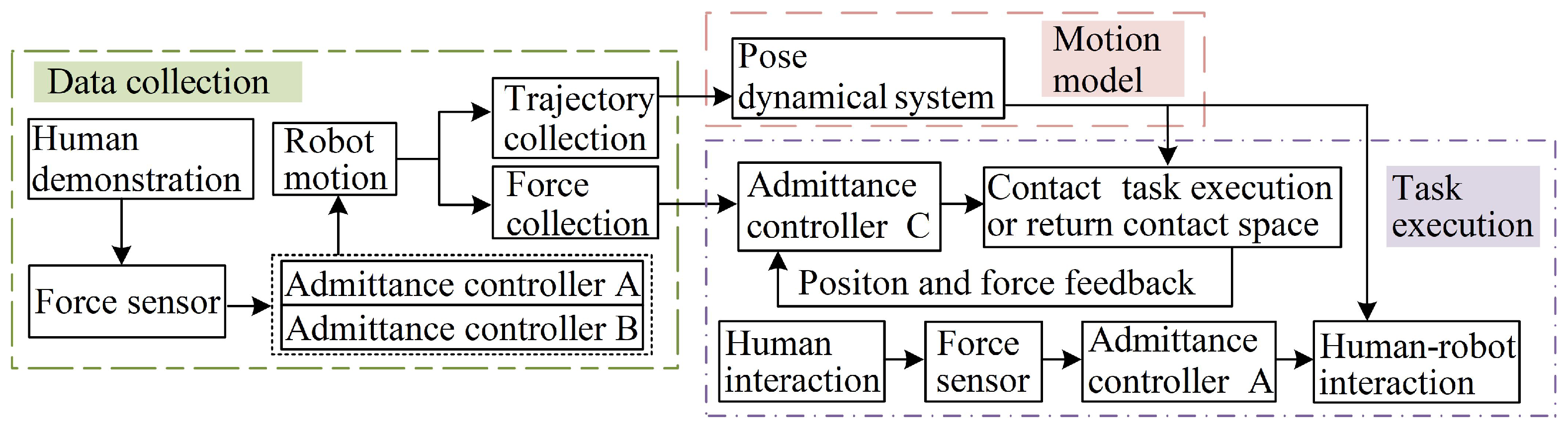
We provide a contact task skills learning framework for the position-controlled robot to reproduce both the trajectory and the force of the human skills and achieve interaction with the human compliantly during the robot operation.
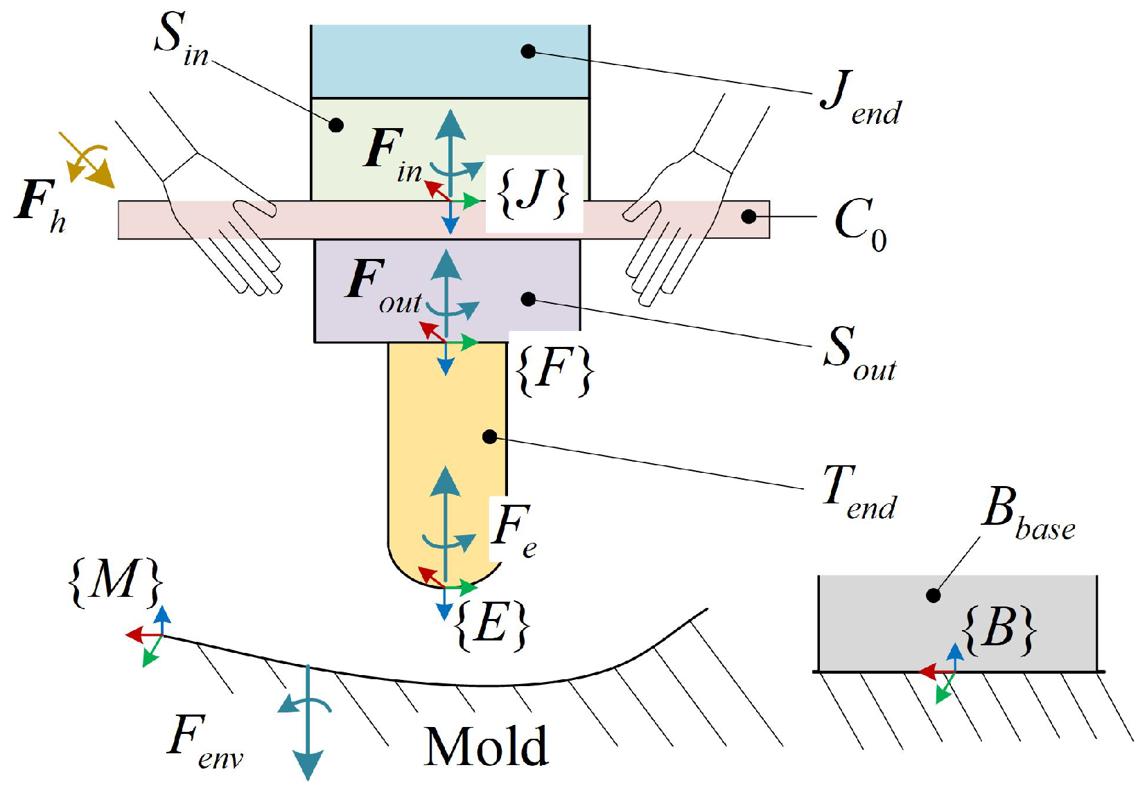
The rest of this paper is organized as follows: Section 2 will introduce the proposed framework and methodology for learning contact task skills from demonstration and achievement of the execution of the contact task with human interaction. The experimental validation and the experimental results are presented in Section 3. Finally, Section 4 concludes this work.

2. Methodology

In this section, we first introduce the proposed framework, which includes data collection, motion model, and task execution, as shown in Figure 1. The statement has been changed in the manuscript. Firstly, the data of the person completing the contact task were collected through two demonstrations. For the first demonstration, the robot was controlled by admittance controller A. For the second demonstration, the robot was controlled by admittance controller B. The two demonstrations will be introduced in detail in Section 2.1.
Then, the time-invariant pose DS of the contact task was learned by the pose diffeomorphic DS with the demonstration trajectory in Section 2.2. Finally, different motion controllers were designed for various demands during the task execution based on the pose DS and admittance controller in Section 2.3. In order to obtain the desired contact force in the contact space, the robot motion was controlled by modulating the z-direction velocity of the pose DS with admittance controller C. During the task execution, if a human interacted with the robot, the admittance controller A adjusted both linear and angler velocity to move along the intention of the human under the pose DS. Considering that the robot needs to resume working after the interaction, the velocity of the robot was generated by the pose DS on the fly, which was modified by admittance controller A.

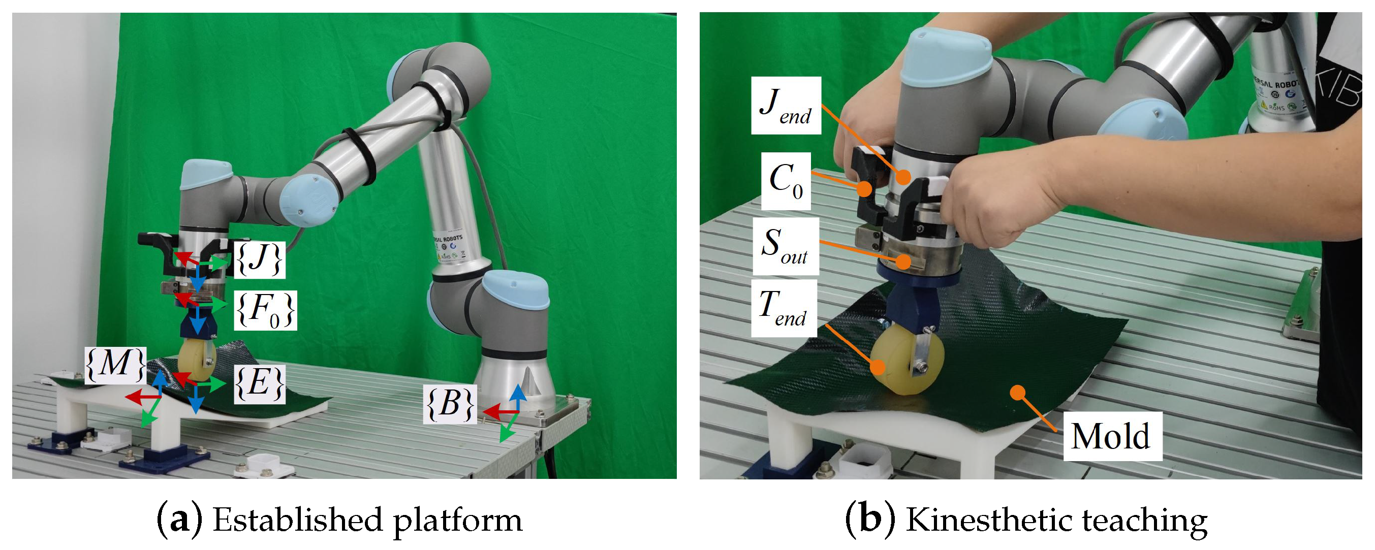
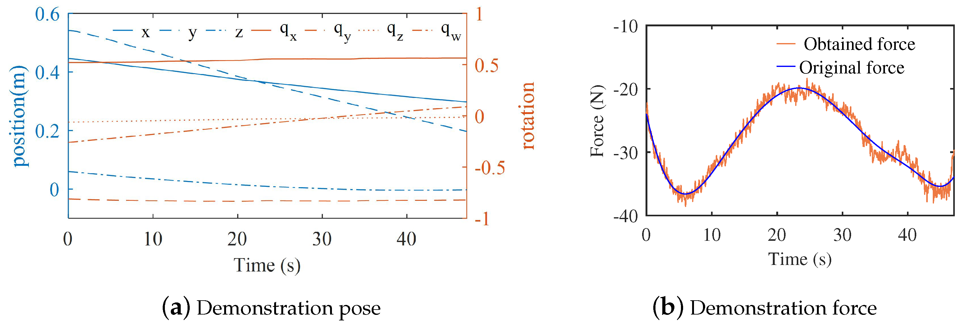
2.1. Human Demonstration

In industrial tasks such as polishing and layup, to a great extent the contact force in the normal direction of the contact surface affects the manufacturing quality for the contact task. Thus, the normal contact force is expected to be obtained in the normal direction of the surface during the human demonstration. However, it is difficult for an operator to perform a task keeping the z-direction of the end-effector along the normal surface. We adopted two demonstrations to collect information about the human performing a contact task, which included both trajectory and force. The position of the robot motion was collected by the human moving the end-effector arbitrarily during the first demonstration. The normal vector of the demonstration position on the surface can be obtained from the information of the surface. For the second demonstration, the robot moved along the first demonstration position, while the z-direction of the end-effector was the same as that of the normal surface. Furthermore, the human exerted force on the end-effector along the z-direction of the end-effector. Thus, the demonstration force was obtained by the second demonstration.
Data were collected through kinesthetic teaching with the demonstration platform, which included a free-form surface mold, UR5e robot with an internal six-dimension force/torque sensor  S i n  in the robot end tool  J e n d , a handle  C 0 , another six-dimension force/torque sensor  S o u t , and an end-effector  T e n d  for executing contact tasks. The position relationships and all coordinates of the platform components are shown in Figure 2. The  T e n d  coordinate system  { E }  and the sensor  S o u t  coordinate system  { F }  were shifted along the z-axis of the  J e n d  coordinate system  { J } . The directions of the mold coordinate system  { M }  were the same as those of the base coordinate system  { B }  of the robot base  B b a s e . The human demonstrated a task by grasping the  C 0  and pushing the  T e n d  on the surface of the mold with force  F h R 6 × 1 . The  F e R 6 × 1  and  F e n v R 6 × 1  are action and reaction forces between the  T e n d  and the mold. The force/torque  F i n R 6 × 1  is the measured value of  S i n F i n  is composed of human interaction force  F h F e , and the gravity of components below the  S i n . Meanwhile, the force/torque  F o u t R 6 × 1  is the measured value of  S o u t F o u t  is composed of  F e  and the gravity of  T e n d .
When the human demonstrated, the robot motion was controlled by the admittance control scheme. For the first demonstration, admittance controller A was used to control the end-effector to follow the human hands moving. To avoid the robot movement being affected by the external gravity of  C 0 S o u t  and  T e n d , the gravity was compensated for with  S i n . After the gravity was compensated for, the value of  S i n  became  F i n . Admittance controller A can be written as:
M ξ e ¨ + B ξ e ˙ = F e x t ,
with
F ext = J B T F i n = J B R 0 3 × 3 P t 0 J B R J B R F i n ,
where the mass  M R 6 × 6  and the damping  B R 6 × 6  are diagonal symmetric definite matrices;  ξ e = [ x e , θ e ] T  is the pose of  { J } F i n = [ f i n , τ i n ] T J B T  is the force transform matrix from  { J }  to  { B } J B R  is the rotation matrix,  P t 0  is the skew-symmetric matrix of the vector  J B P . When the end-effector is in the free space,  F i n  is equal to  F h .
In the method of discrete-time step, the commanded pose  ξ c h  of the robot is expressed as:
ξ c h ( k ) = d t ξ ˙ c h ( k ) + ξ e ( k ) ξ ˙ c h ( k ) = F e x t ( k ) B ξ ˙ c h ( k 1 ) M d t + ξ ˙ c h ( k 1 ) ,
where  ξ e  is the real pose of the robot;  ξ ˙ c h  is the commanded linear and angular velocity;  d t  is the control period; k is the time step.
For the first demonstration, the trajectory  ξ 0 = { x 0 , q 0 }  of  { J }  was collected in  { B } . The normal vector  N z  of  x 0  on the mold surface can be obtained based on the Standard Triangle Language (STL) in  { B } N z  is taken as z-axis of the  { J }  in  { B } . The direction of the  { J }  motion is  N y 0 , which is taken as y-axis of the  { J }  in  { B } . The new x-axis of  { J }  in  { B }  can be expressed as:
N x = N z × N y 0 .
The new y-axis  N y  is perpendicular to  N x  and the z-axis, so  N y  can be written as:
N y = N z × N x .
Through Equations (4) and (5), the desired orientation of the  { J }  in  { B }  is  { N x , N y , N z } . Further, it can be represented by the four components of the quaternion  q 1 = ( q w 1 , q x 1 , q y 1 , q z 1 ) T  [34].  ξ 1 = x 0 , q 1  is taken as a reference trajectory for the second demonstration. The pose of the robot end joint was controlled by the original position controller of the robot with the trajectory  ξ 1  except for the z-direction position. For the second demonstration, the z-direction position was controlled by admittance controller B, which is one dimension of admittance control. The admittance controller B can be expressed as:
m x ¨ + b x ˙ = f e x t ,
where m is mass; b is damping; x is the z-direction position of the end joint;  f e x t  is the z-direction force of  F e x t . The z-direction commanded position can be obtained by the same calculation as Equation (3). Thus, the z-direction of the end joint moves following the force of the human hands.
The contact force between the end-effector and the mold in  { E }  is calculated as:
F e = F E T F o u t = F E R 0 3 × 3 P t 1 F E R F E R F o u t ,
where  F E T  is the force transform matrix from  { J }  to  { B } F E R  is the rotation matrix;  P t 1  is the skew-symmetric matrix of the vector  F E P F o u t  is obtained by gravity compensation for  F o u t .
The force/torque  F d e m o = F e  in  { E }  and the trajectory  ξ d e m o = { x d e m o , q d e m o }  of the  { E }  in  { B }  are collected by the second demonstration. Finally,  F d e m o  and  ξ d e m o  are taken as the demonstration force and trajectory.

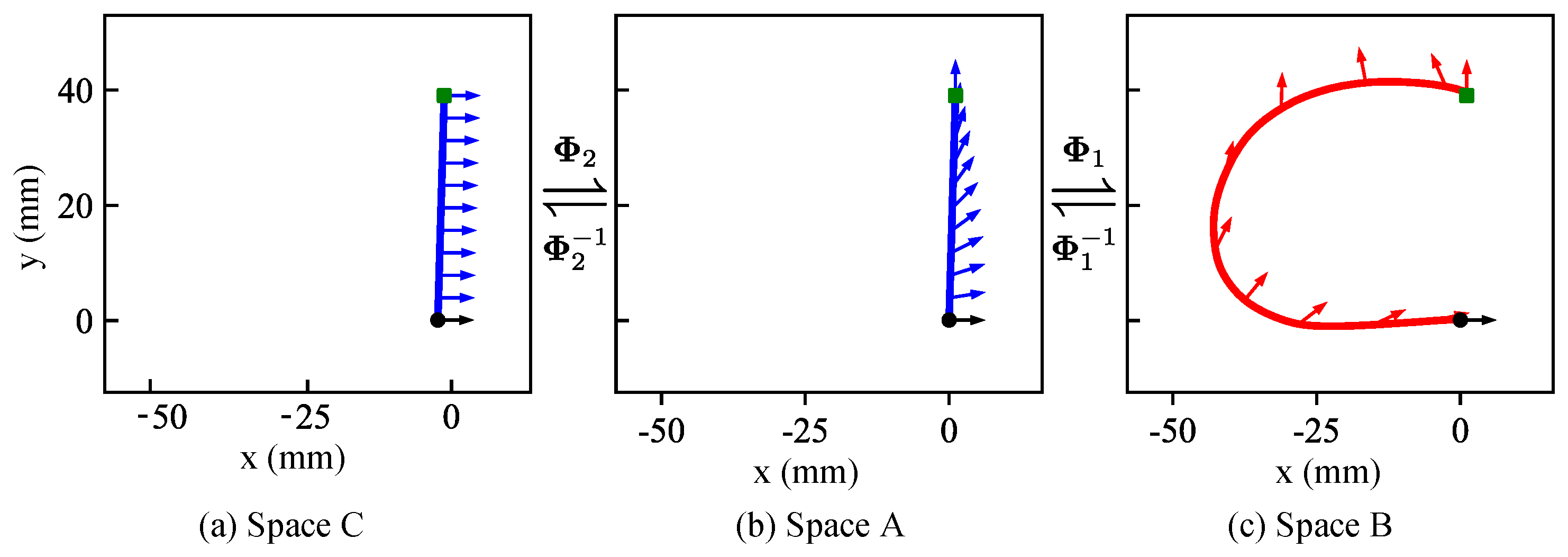
2.2. Pose DS Establishment

In order to represent the human demonstration trajectory for contact tasks, the demonstration trajectory was modeled by the pose DS through diffeomorphic mapping. Meanwhile, the diffeomorphic mapping was established between the trajectories in different spaces. As shown in Figure 3, there are three spaces, which are  A B  and  C . A new trajectory can be obtained by subtracting the end point pose of the demonstration trajectory from the demonstration trajectory pose in the space  B . As shown in Figure 3c, the trajectory in the real space  B  is obtained from the LASA handwriting dataset [13] using the method. To establish orientation DS based on the position, the simple trajectories were developed in the latent space  A  and latent space  C . The position in space  A  and space  C  is a simple straight line from the start point and end point of the trajectory in space B, as shown in Figure 3a,b. The orientation of every point in space C is equal to the unit quaternion  [ 1 , 0 , 0 , 0 ] T . The orientation in space A is obtained by the method of interpolate between the orientation of the start point and end point of trajectory in space B.
Based on the trajectories in different spaces, the diffeomorphic mapping  Φ 1  from spaces  A  to  B  and the other diffeomorphic mapping  Φ 2  from spaces  C  to  A  were established for both position and orientation with the iterative method [35]. Based on the diffeomorphic mappings and established pose DS in  A , the motion online planning is realized in  B .
The new trajectory  ξ B = { x B , q B }  is obtained by taking the endpoint  ξ e n d = { x e n d , q e n d }  of  ξ d e m o  as equilibrium point  { 0 , q I } , with   q I = [ 1 , 0 , 0 , 0 ] T . The trajectory  ξ B  is expressed as:
x B = x d e m o x e n d q B = q e n d 1 q d e m o .
The simple trajectory  ξ A = { x A , q A }  in  A  is generated by:
x A = t x B 1 q A = q B 1 t ,
where  t = N i N 1 ( i = 1 , 2 , N ) , N is the sample size of the demonstration trajectory,  { x B 1 , q B 1 }  is the first point pose of the trajectory  ξ B .
The other simple trajectory  ξ C = { x C , q C } = { x A , q I }  is developed in the space  C Φ 1  and  Φ 2  are expressed as:
Φ 1 : x B = h 1 ( x A ) q B = g 1 ( x A ) q , Φ 2 : x A = x C q A = g 2 ( x C ) .
The established DS in the space  A  can be expressed as:
x ˙ = γ 1 ( x ) Px , γ 1 ( x ) > 0 w = γ 2 ( q ) β log q g ¯ 2 ( x ) + w r , β < 0 ,
with
γ 1 ( x ) = x 1 N Δ t x 1 , x x 1 N 1 Δ t , otherwise .
where the point  { x , q }  in  A w  is the angular velocity of the orientation DS in  A w r = 2 q g ¯ 2 ( x ) x g 2 ( x ) q ¯  is the feedforward term;  P  is the symmetrical negative matrix factorization;  γ 2 ( q ) = 1 .
The online pose in  C  can be calculated by two inverse mappings of Equation (10) with the pose  { x B , q B }  in  B . The position in  C  is the same as the position in  A  in Equation (10), but the orientation is different in two spaces. Then, the result of the orientation mapping is taken as the goal orientation in  A  through the forward mapping from  C  to  A . The desired linear and angular velocity can be obtained in  A  with Equation (11). The increment of the pose in the  A  space for the next time step can be obtained by multiplying the desired velocity by the control period. The expected pose in space A can be obtained by adding the increment of the pose to the current pose. Further, the desired pose in  B  can be obtained by forward mapping in Equation (10). Thus, the time-invariant pose DS is established for the demonstration trajectory.
When the robot starts moving with an arbitrary pose, the robot pose will be the same as endpoint of the demonstration trajectory at last, but it cannot immediately obtain the desired orientation when the position changes [21]. For the contact task, it is necessary for the robot to move along both the position and orientation of the demonstration trajectory during task execution. Meanwhile, the robot must recover its desired orientation immediately from a large orientation error after human interaction. We adjusted the orientation DS by changing  γ 2 ( q )  to 1 to achieve the desired orientation immediately.

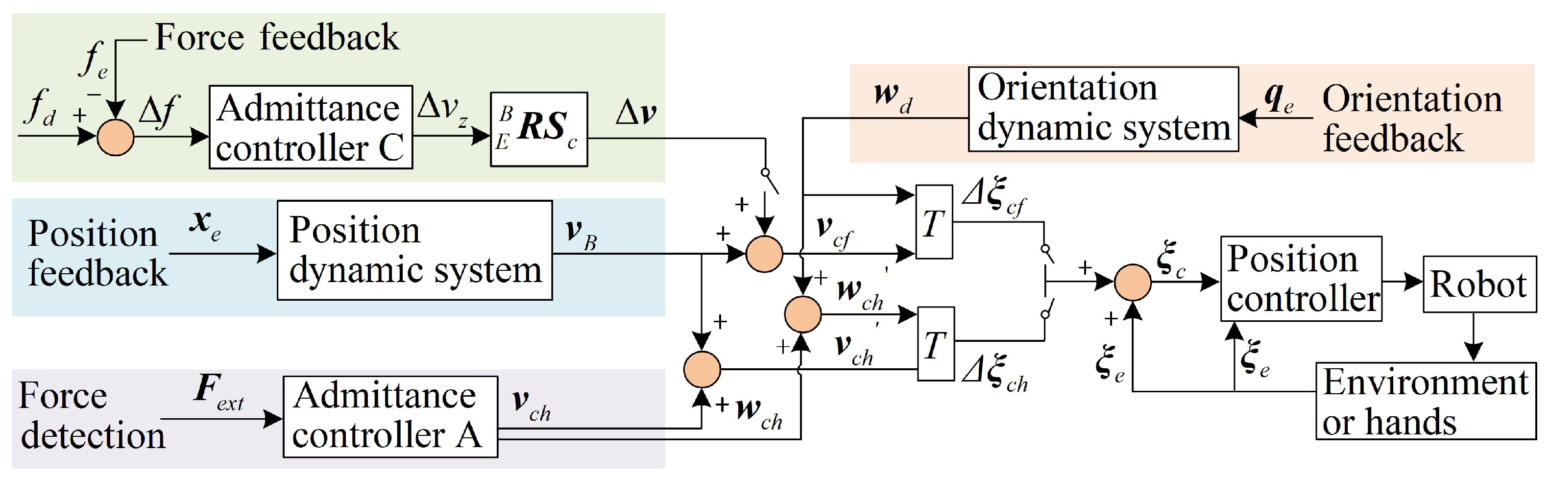
2.3. Motion Controllers for Reproducing

As stated in Section 2, we divided the task process into three subtasks for the robot: reaching the contact space, executing the contact task, and interacting with the human. We designed the different motion controllers for the three subtasks, respectively, which are shown in Figure 4. The only difference between the first and the second subtask is the value of the desired force, which determines how long it takes for the robot to reach the contact space from the free space and the value of contact force in the contact space, respectively. The motion controllers were designed for the first and the second subtasks based on admittance controller C. Furthermore, the other motion controller was developed to handle the third subtask of human–robot interaction based on admittance controller A.
Admittance controller C was used to modulate the position DS in the z-direction to track the desired contact force in the contact space or control the speed of the robot reaching the contact space. For the contact task, the DS motion planning was different from the off-line motion planning, in which offline trajectory and desired force were one-to-one matching. In contrast to the demonstration, online motion mapping and planning characteristics of the diffeomorphic pose DS made the motion steps of online motion not equal to the demonstration sample size. For online motion planning, the desired force can be defined as:
f d = α S f F d e m o i ,
where  S f = [ 0 , 0 , 1 , 0 , 0 , 0 ] F d e m o i R 6 × 1  is the teaching force at the nearest demonstration position from the current point;  α > 0  is the regulation coefficient of desire force/torque. When the robot executes the second subtask,  α  is 1. In the first subtask, the speed of the robot reaching the contact space was modified by the value of  α , which must be an appropriate value to avoid a large collision force for the robot reaching contact space.
The commanded linear velocity  v c f  is obtained by combining  Δ v  and the velocity of the position DS  v B . It can be written as:
v c f = v B + Δ v ,
where  Δ v = E B R S c = E B R ( S z Δ v z ) E B R  is the rotation matrix,  S z = [ 0 , 0 , 1 ] T Δ v z  is the z-direction excepted velocity produced by the admittance controller C.
As the angular velocity  w d  is calculated by the orientation DS, the commanded velocity of the pose is  ξ ˙ c f = { v c f , w d } . The robot moves without a reference trajectory, compared with the traditional admittance controller architecture, so let us define the commanded pose  ξ c = [ X c , q c ] T  as:
ξ c = ξ e + ξ ˙ c f d t .
The  Δ v z  can be obtained from admittance controller C. The principle of admittance controller C can be expressed as:
m f e ¨ + b f e ˙ + k f e = Δ f ,
where  m f b f  and  k f  are the mass, damping, and stiffness with the appropriate values, respectively; e is the error between the commanded z-direction position and real z-direction position in  { E } Δ f = f d f e f e  is the z-direction contact force of  F e x t .
Equation (16) can be converted to its discrete format as:
x ˙ c z ( k ) = x ¨ c z ( k ) d t + x ˙ e ( k ) x ¨ c z ( k ) = Δ f ( k ) b f [ x ˙ c ( k 1 ) x ˙ e ( k ) ] k f [ x c ( k 1 ) x e ( k ) ] m f + x ¨ e ( k ) ,
where  x ˙ c z  and  x ¨ c z  are expected velocity and acceleration produced by the admittance controller C;  x c  and  x ˙ c  are the z-direction position and the velocity of  B E R X c  and  B E R v c f x e x ˙ e , and  x ¨ e  are the z-direction position, velocity, and acceleration of the end-effector in  { E } .
When the human interacts with the robot with the force over the threshold in the x-orientation or y-orientation, the subtask changes from the second to the third subtask. Meanwhile, the robot is controlled by the third motion controller. The robot will move following the human intention with the pose modulation, which is calculated by the admittance controller A of Equation (1) through the contact force between the hands and the robot. In the second motion controller, the commanded pose and velocity of the robot can be expressed as:
ξ c = ξ e + Δ ξ c h Δ ξ ch = d t ( ξ ˙ c h + ξ ˙ d ) ,
where  ξ ˙ d = { v B , w d }  is the velocity of the pose produced by the pose DS;  ξ ˙ c h  is also calculated by Equation (3);  ξ ˙ c h = { w c h , v c h } w c h = w d + w c h , v c h = v B + v c h , in Figure 4.

3. Experiment

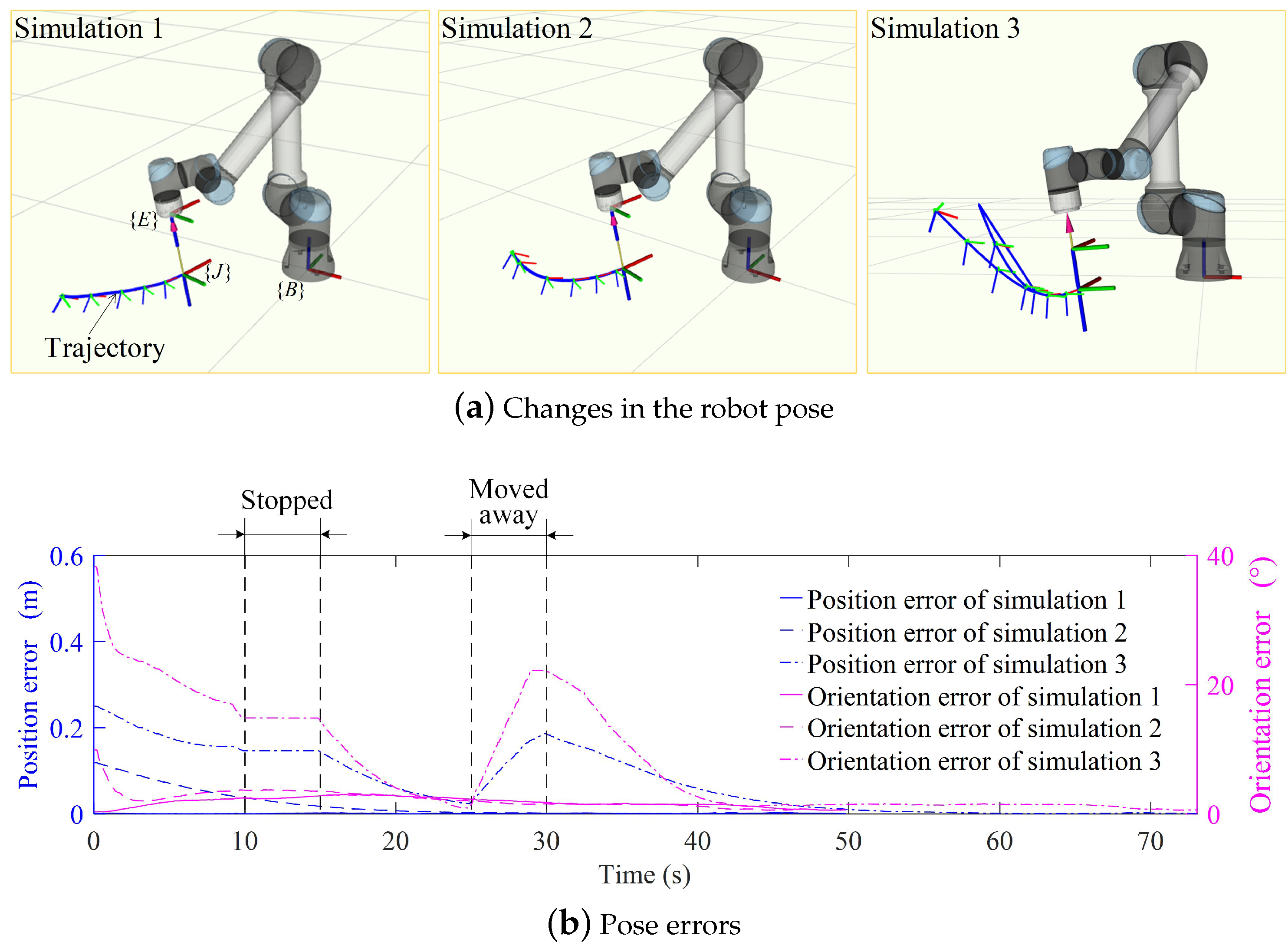
3.1. Contact Task Demonstration and Simulation

We established the platform for both collecting demonstration data and reproducing the human demonstration for the contact task as shown in Figure 5, which includes the same components as Section 2.1. The coordinate systems were established, as shown in Figure 5a. The trajectory and force of human demonstration were obtained by kinesthetic teaching in Figure 5b based on the proposed method in Section 2.1. As the gravity of the  T e n d  was small for the platform, the   F o u t  was approximately equal to  F o u t . When the human demonstrated the contact task, the collecting force was jittery. In order to obtain the smoothed desired force in the z-direction, cubic smoothing splines were used to fit a smooth curve from the original demonstration force. The parameters of admittance controller A were adjusted according to the need for compliant human–robot interactions. When the human demonstrated the task for the first time, the parameters of admittance controller A were set to  M  = diag [1, 1, 1, 1, 1, 1]  Kg B  = diag [ B 1 , B 2 ],  B 1  = diag [0.3, 0.3, 0.3]  Ns / m B 2  = diag [0.03, 0.03, 0.03]  Nms / rad . The parameters of admittance controller B were the same as the parameters of admittance controller A in the z-direction position. For the second demonstration, the parameters of admittance controller B were  m = Kg b = 0.3  Ns / m . The demonstration pose is shown in the Figure 6a, and the demonstration force in the z-direction is shown in Figure 6b.
The pose DS was established based on the method in Section 2.2 with the demonstration trajectory. Our computer had a 3.7 Ghz Intel Core i5-9600KF CPU (six cores) and 16 GB memory. With our approach, the two mappings cost 1.01 s to train the demonstration trajectory. By multiplying the linear and angular velocity calculated by DS in the control period, we obtained the expected pose increment. The control period was set to 0.02 s. The motion was completed when the distance between the current position and the end-point was less than 0.003 m. In order to test the computation efficiency of our method, we conducted a simulation without a robot model. Each running step cost 0.019 s, and the simulation took 11.07 s to complete. We used two group Dynamic Movement Primitives (DMP) [36] to model our demonstration trajectory. We modeled the position of the demonstration data in three dimensions of DMP, and modeled the orientation of the demonstration data in four dimensions of DMP. The time taken to train the demonstration trajectory in the manuscript was 11.72 s with DMP. The time taken to finish the simulation was 0.58 s, and every running step cost 0.00025 s. Compared with the training time of the methods in [13] and DMP, our approach achieved the transfer of the human demonstration to the robot more quickly. To obtain the linear and angular of DS online, the pose in the real space needs to be mapped into the latent spaces for our method. Our approach involved two mappings, which were established based on an iterative method, so completing the mappings online took some time. Therefore, it took a long time to perform the computations online at every time step.
Three simulations were performed without force control to illustrate that the established time-invariant pose DS can reproduce the trajectory of human demonstration and re-plan motion automatically after human interaction for the contact task. The pose of the start point for the first simulation was the same as the first point of the demonstration trajectory, and the other two simulations started from the points with an arbitrary pose in the free space. In the third simulation, the perturbations occurred during the robot movement. The changes in the robot pose are shown in Figure 7a during the three simulations. Meanwhile, the robot pose errors are shown in Figure 7b for the three simulations. The pose errors of the first simulation were always within 0.003 m and 3.0°, so the first simulation trajectory closely coincides with the demonstration trajectory. The established pose DS can reproduce the motion of human demonstration for the contact task. The starting points of the other two simulations had a large pose difference from the demonstration trajectory but, as the robot moved, the position and orientation errors were gradually reduced as shown in Figure 7b. Meanwhile, the perturbations occurred in the third simulation. The robot was stopped at 10∼15 s and moved away at 25∼30 s in the third simulation. As the robot restarted moving after 15 s in the third simulation, it could still move along the demonstration trajectory. The robot pose errors of the third simulation became small again after 30 s. This means the learning pose DS for the contact task is not sensitive to both temporal and spatial perturbations. Finally, all three simulations could obtain a small pose error at the endpoint. Thus, the established pose DS can model the demonstration trajectory well and adapt to different initial poses and perturbations.

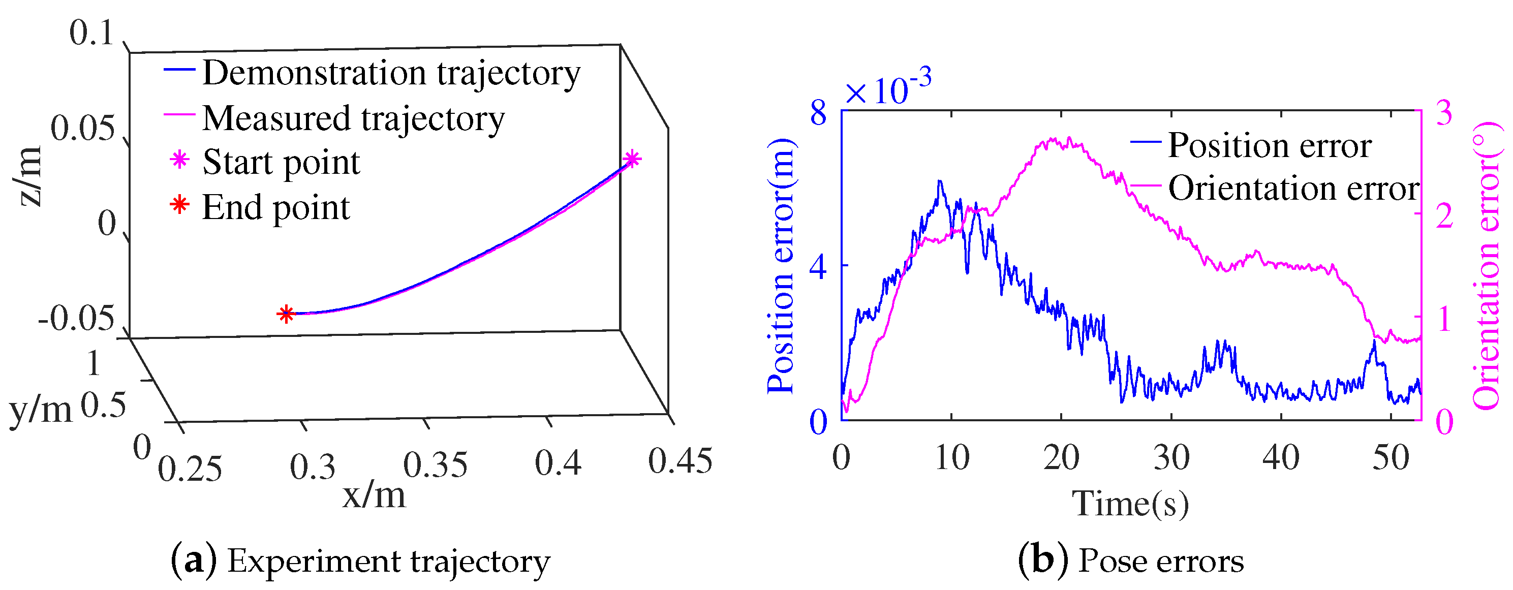
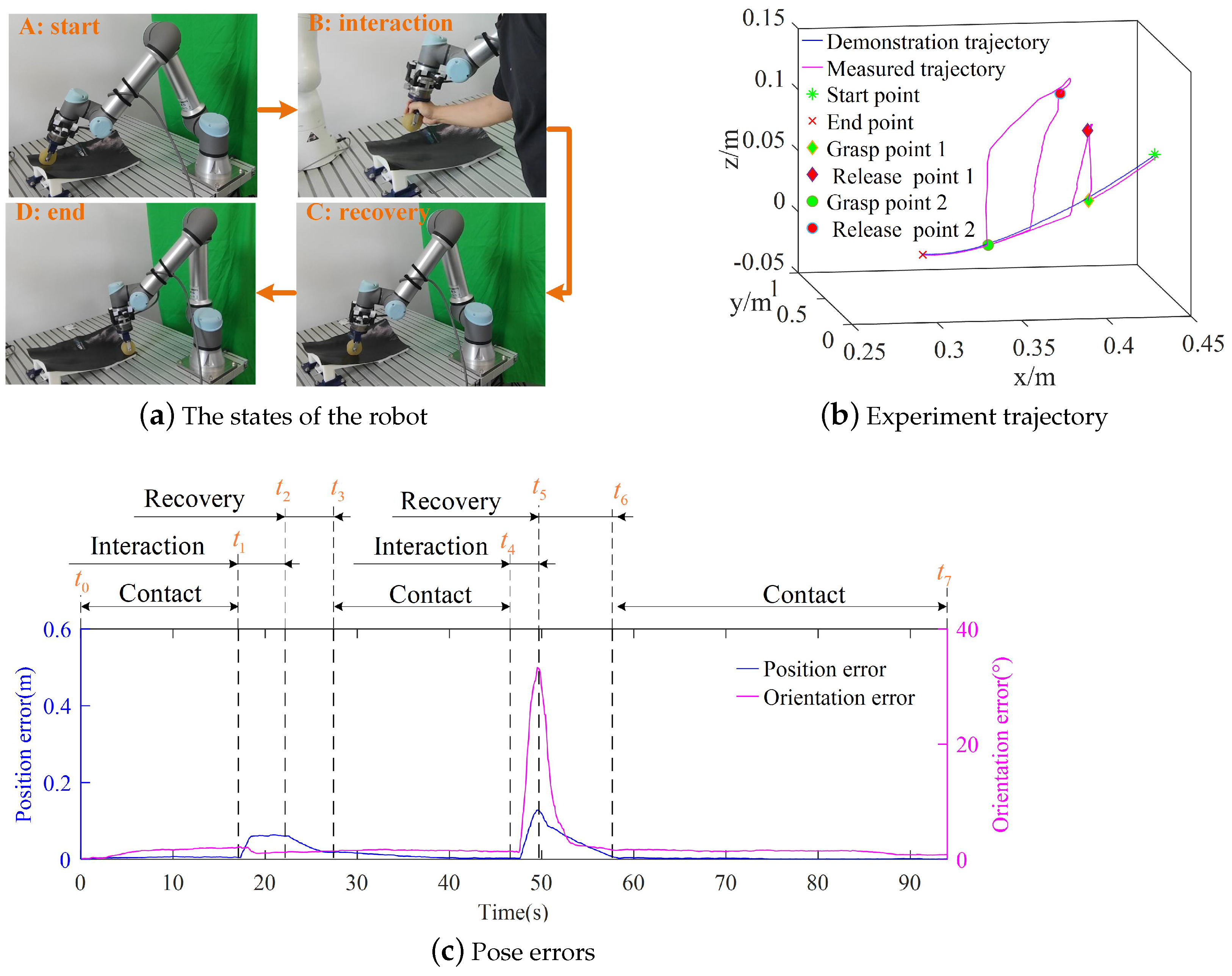
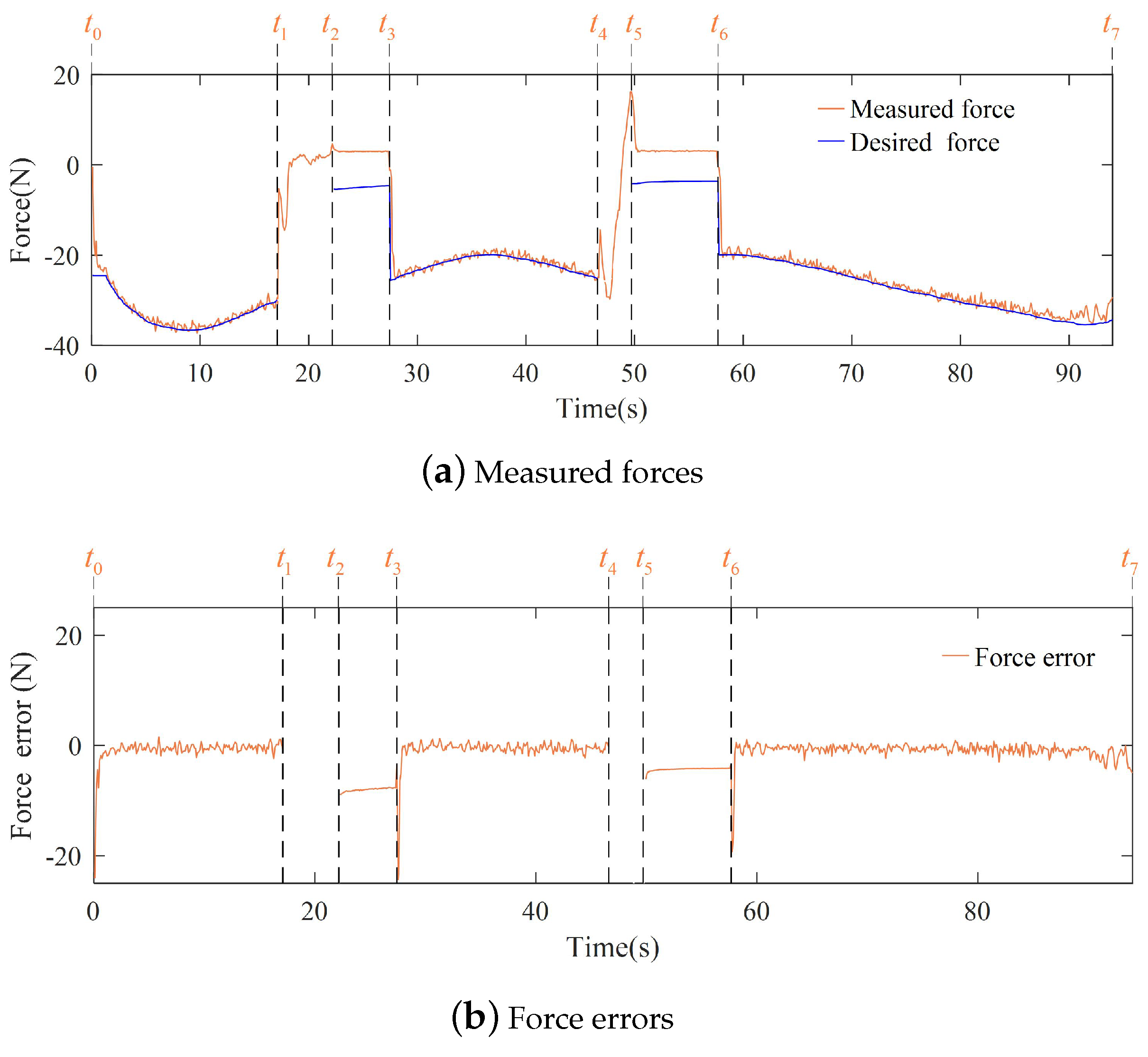
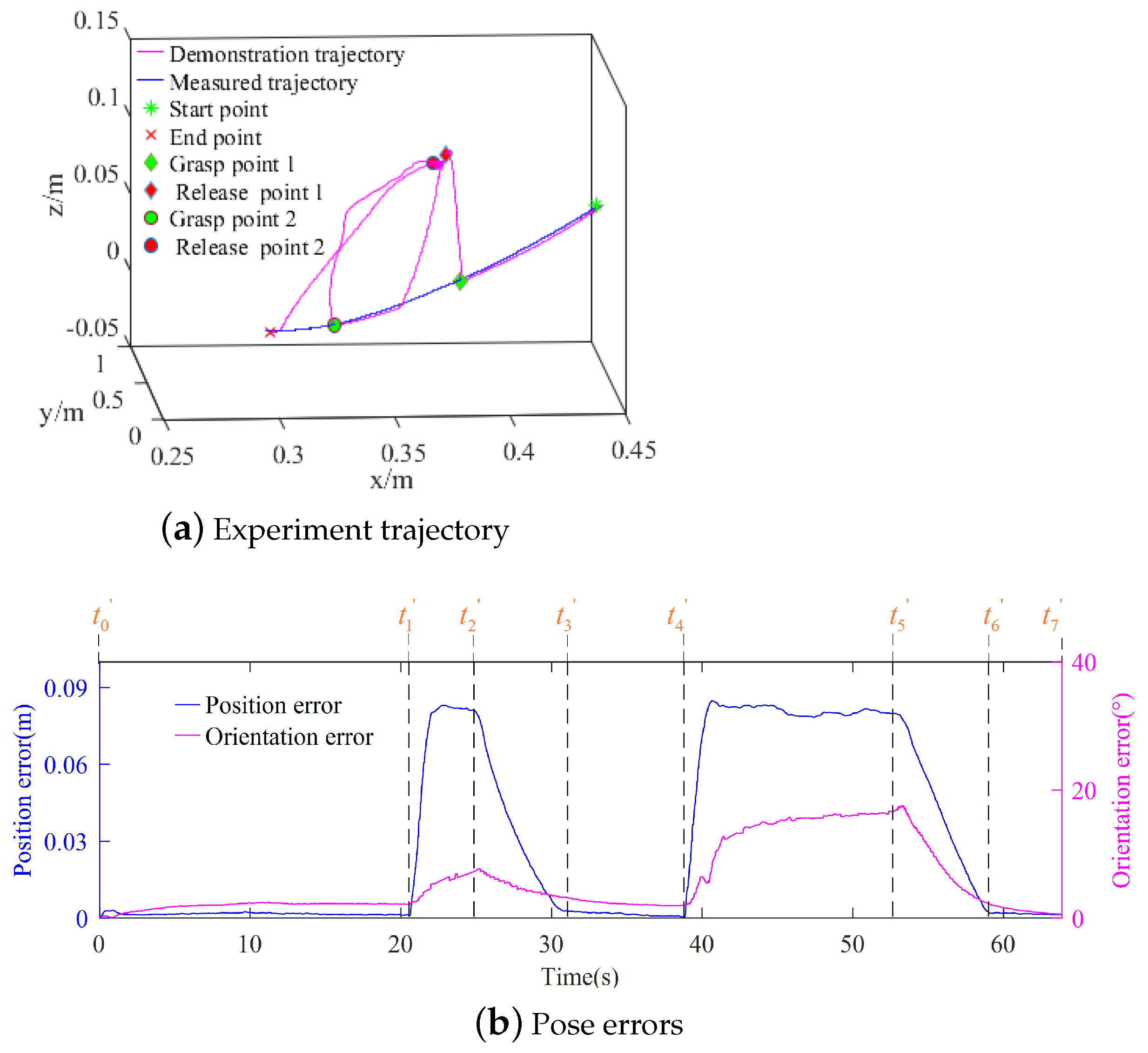
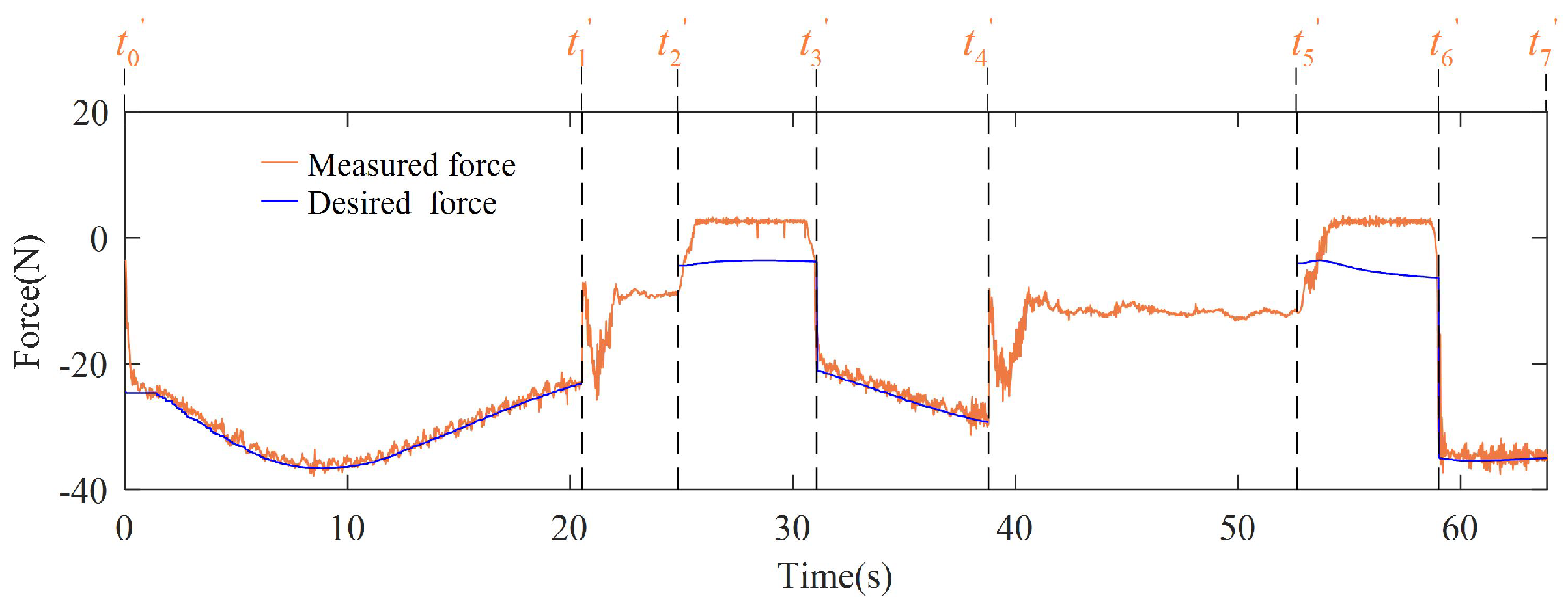
3.2. Experiments of the Contact Task

To verify the effectiveness of our approach, different experiments on contact tasks were performed on the platform in Section 3.1. To explore the result of the method for the robot learning skills of contact task from human demonstration, the first experiment was executed under the motion controller of the second subtask in Section 2.3. The robot began moving from the first point of the demonstration trajectory for the first experiment. Meanwhile, to compare the results of force tracking under the offline motion planning, another experiment was conducted by taking the demonstration trajectory as a reference trajectory. To compare our approach with DMP, the experiment was also carried out under the motion modeled by DMP with no interaction. Another experiment was conducted under the robot moving from free space in our method. When the robot reached the contact space from free space in the experiment, it was controlled by the motion controller of the second subtask in Section 2.3. There were also two experiments under human interaction. For these two experiments, the motion was modeled by our approach and DMP, respectively. When a human interacted with the robot, the robot was controlled by the motion controller of the third subtask in Section 2.3.
The first experiment was conducted in our method under no interaction. The parameters of the admittance controller C can be obtained by being adjusted to obtain less force error in the z-direction. The parameters of admittance controller C were set to  m f  = 1  Kg b f  = 80  Ns / m k f  = 10  N / m . The measured trajectory of the experiment is shown in Figure 8a. The measured trajectory was close to the demonstration trajectory. The pose errors between measured and demonstration trajectory of the first experiment are shown in Figure 8b. The position errors were within 0.008 m, and the orientation errors were within 2.75°. The root mean square error (RMSE) of position and orientation were 0.003 m and 1.77°, respectively. The small pose errors showed good reproduction of the demonstration motion under the robot motion controller of the second subtask in Section 2.3.
The contact force and force error between the measured and desired force of the experiment are shown in Figure 9 for the proposed method. When the robot starts moving, the force error is the biggest. The biggest absolute value of the force error is 4.18 N, except for the beginning of motion. The RMSE of force is 1.04 N for the whole process of the experiment. The demonstration trajectory increases at the position close to the endpoint, as shown in Figure 8a. When the robot moves near the endpoint of the demonstration trajectory, the robot motion tends to the endpoint of the demonstration trajectory. This results in bigger positive force errors near the endpoint of the demonstration trajectory, as shown in Figure 9b. The proposed method can realize the reproduction of the demonstration force. To explore the repeatability of the reproducing demonstration, the experiment was repeated ten times under the same parameters of admittance controller C. For the ten experiments, the RMSE of position and orientation were 0.003 m and 1.78°, respectively. Meanwhile, the RMSE of the contact force was 1.04 N. The proposed method can achieve reproduction of both the trajectory and the force.
The contact force and force errors of the experiment with offline motion planning are shown in Figure 10. The biggest absolute of the force error is 3.44 N, except for the beginning of motion. The RMSE of force is 1.06 N of the whole process of the experiment. The second experiment was also repeated ten times. For all repeated experiments, the RMSE of the contact force was 1.07 N. Compared with the commanded velocity of force tracking under offline motion planning, the commanded velocity for the second subtask was obtained by combining the pose dynamical system and the modulation velocity calculated by admittance controller C. Meanwhile, the commanded pose was obtained by adding the position increment to the current pose. That resulted in the smaller force errors change, but it had a greater number of positive force errors near the endpoint. The proposed method obtains a similar RMSE of force to the method of offline motion planning.
When the robot executes the contact task under motion modeled by DMP, it is controlled to obtain the desired motion and force by the the same motion controller of the second subtask as in the first experiment. Compared with the parameter of admittance controllers in the first experiment, the parameters of admittance controller C are the same. In the experiment, the robot reproduced the contact task under no interactions. The contact force and force error were obtained as shown in Figure 11. The biggest force error was 3.57 N, and the root mean square error (RMSE) of the force was 1.36 N. The experiment was also repeated ten times under the same parameters of admittance controller C. The RMSE of the contact force was 1.11 N for the ten repeated experiments. The results of force and force error are close to those of off-line motion planning for the motion modeled by DMP. Compared with methods of the off-line and DMP motion planning, the proposed method obtains a similar RMSE of force.
The measured trajectory of the experiment is shown in Figure 12a under the robot moving from the free space. As the robot moves from the free space, the measured trajectory gradually becomes close to the demonstration trajectory. When the robot reaches the contact space, the value of  α  is 0.18 in the motion controller of the second subtask. The pose errors of the whole process of the robot motion are shown in Figure 12b. The contact force and force errors of the experiment are shown in Figure 13. The robot reaches contact space and is controlled by the motion controller of the first subtask after 7 s, which modulates the robot motion to obtain the desired force. When the robot reaches the contact space, both the position and orientation errors can continue reducing, as shown in Figure 12b. When the robot tracks the desired force, the biggest absolute value of the force error is 4.44 N. The proposed method can ensure the robot begins working from free space.
The process of the experiment with interactions is shown in Figure 14a. Because the linear and angular velocity of DS exists, the parameters of admittance controller A are different to those in the demonstration. The method of obtaining the parameters of admittance controller A is also based on compliant human–robot interaction. When the operator interacts with the robot, the parameters of admittance controller A are set to  M  = diag [0.8, 0.8, 0.8, 0.1, 0.1, 0.1]  Kg B  = diag [ B 3 , B 4 ],  B 3  = diag [0.4, 0.4, 0.4]  Ns / m B 4  = diag [0.4, 0.4, 0.4]  Nms / rad  for the proposed method. At first, the robot starts working from the first point of the demonstration trajectory in the contact space under the motion controller of the first subtask, as shown in Figure 14a. When the human interacts with the robot with force larger than the threshold value, the motion controller is changed into the motion controller of the third subtask. The threshold value of force is 8 N in the y-direction. There were two interactions in the experiment. For the two interactions, the human grasped and moved the end-effector, respectively, as shown in the second picture of Figure 14a. For the first interaction, the operator moved the end-effector away from the contact space at  t 1  (17.1 s) and held it in the free space at  t 1  (17.1 s)∼ t 2  (22.1 s). The end effector was moved under human intention compliantly in the free space for the second interaction at  t 4  (46.7 s)∼ t 5  (49.7 s). When the absolute value of the x-direction force was less than 4 N and the absolute value of the y-direction force was less than 2 N, the interaction was considered finished. As soon as the absolute value of the z-direction force reached 3 N, the robot reached the contact space and resumed its operation. After the two interactions, the robot resumed executing the contact task from free space at  t 3  (27.3 s) and  t 6  (57.7 s), as shown in the third picture of Figure 14a. Finally, the robot reached the endpoint as shown in the fourth picture of Figure 14a. The trajectory of the experiment is shown in Figure 14b. The human began interacting with the robot at grasp point 1 and grasp point 2 in Figure 14b, respectively. The robot was released at release point 1 and release point 2, respectively. When the robot reached the mold surface after the interactions, the robot resumed executing the contact task again. The pose errors of the whole process are shown in Figure 14c. During the first interaction, the value of pose errors kept increasing and was at a near constant value at 18.5∼22.1 s. For the second interaction, the pose errors became large as the robot moved away from the mold. The human can drag the robot moving in the free space as shown in the second picture of Figure 14a. When the human released the robot at the release point in Figure 14b, the motion controller changed back to the first motion controller for the first subtask in Section 2.3. After the robot was released, both the position and orientation errors reduced quickly. When the robot executed the contact task, the biggest position error was 0.02 m after the first interaction in Figure 14c. After the robot resumed executing the task, the pose errors could decrease under force control. The biggest orientation error was 2.0° for the robot executing the contact task in Figure 14c. Finally, the robot reached the endpoint along the demonstration trajectory with a small pose error.
The changes in contact force and force errors of the experiment are shown in Figure 15. When the human interacted with the robot at  t 1 t 2  and  t 4 t 5 , there was no desired force. After the interaction, the robot recovered the contact task from free space under the 0.18 times the desired force at  t 2 t 3  and  t 5 t 6 . This achieved the robot resuming working quickly. When the robot executed a task independently, the biggest force error was 4.50 N near the endpoint of the trajectory. The proposed framework can realize the robot learning the skills of a contact task from human demonstration and interacting with a human during the task execution.
Another experiment was conducted under motion modeled by DMP and interaction. In this experiment, there were two interactions. The parameters of admittance controller A were set to  M  = diag [0.4, 0.4, 0.4, 0.04, 0.04, 0.04]  Kg B  = diag [ B 5 , B 6 ],  B 5  = diag [0.4, 0.4, 0.4]  Ns / m B 6  = diag [0.4, 0.4, 0.4]  Nms / rad . The parameters of admittance controller A were adjusted according to the need of compliant human–robot interactions. The two interactions occurred in the middle and near the end of the demonstration trajectory, respectively. As shown in Figure 16a,b, the experiment trajectory and pose error are presented, respectively. At  t 1 (20.53 s), the operator grasped the end-effector and moved it away from the contact surface for the first interaction. The robot recovered execution of the task at  t 3 (31.07 s) after being released at  t 2 (24.85 s). The other interaction occurred at  t 4 (38.79 s), and the robot was released at  t 5 (52.65 s). After the second interaction, the robot reached the contact space at  t 6 (59.01 s). It took about 53.51 s for the robot to complete the task under no interaction as shown in Figure 1. As soon as the robot was released after the first interaction, the forcing term of the DMP drove the robot to move toward the demonstration trajectory. After the second interaction finished, the time was close to the time of the robot accomplishing the task independently. Meanwhile, since the forcing term of the DMP is time-related, the robot was unable to return to the pose before the interaction. After the second interaction, the robot was mainly controlled by the second-dynamic system of the DMP, which ensured the robot moved to the end-point of the demonstration trajectory.
In Figure 17, the contact force human interaction is presented. As the robot moved toward the end point after the second interaction, there was no contact force between  t 5 (52.65 s) and  t 6 (59.01 s). Thus, after an interaction, if the time exceeds that of the robot executing independently, the robot is not able to recover execution of the contact task under the motion modeled by DMP. After being released by the human, the robot can recover the close pose of the demonstration trajectory using our approach, as shown in Figure 15b. For the second interaction, the released point was in front of the grasp point, and the recontact point was also in front of the released point as shown in Figure 15b.

3.3. Discussion

Our algorithm can be generalized to different scenarios, such as polishing, wiping, pressing etc. Meanwhile, it can deal with the interaction during the robot execution of the task. There is no force control mode available on most commercialized robots, which places an emphasis on following position with accuracy. Our framework is suitable for a position-controlled robot. These tasks require the robot to move along the planning trajectory and to obtain the desired force. The trajectory and force can be obtained by the method of kinesthetic teaching for those tasks in this manuscript. By adjusting the parameters of admission controllers A and C, the method of kinesthetic teaching in this manuscript can be accomplished for the different tasks, end-effectors, and robots.
The algorithm can quickly model the motion based on the demonstration data in the paper. Meanwhile, both the orientation and the position can be modeled based on our approach. Admittance controller C modulates the robot motion to obtain the desired force. The parameters of controller C can be obtained by manual adjustment online, based on the results of force tracking. According to the results of the experiments in Section 3.2, our approach can reproduce the demonstration from the contact space or the free space. When the human interacts with robot, the robot can move along with the human intention. Compared with the method of motion planning by DMP, these approaches can make the robot return to the demonstration trajectory near the released point. A compliant human–robot interaction can be achieved by adjusting the parameters of admittance controller A. Thus, our approach can achieve robot execution of tasks in a more complex environment, such as at home or at the hospital. Meanwhile, the robot will be able to perform more diverse contact tasks, such as robotic ultrasound scanning [37] and massage [38].

4. Conclusions

We proposed a framework for robots learning contact task skills from human demonstration, which considers trajectory, contact force, and human–robot interaction. Through two demonstrations, the demonstration trajectory and force were collected. To achieve robot motion planning online, a time-invariant DS was built to model the motion. Further, to reproduce the motion and contact force with human interaction, the entire contact task execution was separated into three subtasks, for which two motion controllers were developed based on the pose DS and different admittance control schemes. Experiments with the UR5e robot verified that the robot can reproduce contact task skills of human demonstration. For experiments repeated ten times under the same motion controller parameters and with no interaction, the RMSE for position, orientation, and force were 0.003 m, 1.78°, and 1.04 N, with the robot executing the task independently. Compared with the method of motion planning with the DMP and offline, the results of force tracking are similar. When the human interacts with the robot, the robot can succeed in moving with human intention. In our method, the robot is able to reach the demonstration trajectory near the released pose after human interaction, compared with the motion modeled by the DMP. In the future, to increase the acceptability and usability of the proposed approach, we will consider developing strategies to achieve higher computation efficiency.

Author Contributions

S.Y. contributed to the modeling, controller design, and simulation results of learning pose DS from human demonstration. X.G. contributed to the experimental results. Z.F. and X.X. contributed to the design concept and writing. All authors have read and agreed to the published version of the manuscript.

Funding

This research was funded by National Key R&D Program of China (2018YFB2100903).

Institutional Review Board Statement

Not applicable.

Informed Consent Statement

Not applicable.

Data Availability Statement

Data sharing is applicable.

Conflicts of Interest

The authors declare no conflict of interest.

References

  1. Gao, X.; Ling, J.; Xiao, X.; Li, M. Learning force-relevant skills from human demonstration. Complexity 2019, 2019, 5262859. [Google Scholar] [CrossRef]
  2. Malhan, R.K.; Shembekar, A.V.; Kabir, A.M.; Bhatt, P.M.; Shah, B.; Zanio, S.; Nutt, S.; Gupta, S.K. Automated planning for robotic layup of composite prepreg. Robot. Comput. Integr. Manuf. 2021, 67, 102020. [Google Scholar] [CrossRef]
  3. Amanhoud, W.; Khoramshahi, M.; Bonnesoeur, M.; Billard, A. Force adaptation in contact tasks with dynamical systems. In Proceedings of the 2020 IEEE International Conference on Robotics and Automation (ICRA), Paris, France, 31 May–31 August 2020; IEEE: New York, NY, USA, 2020; pp. 6841–6847. [Google Scholar]
  4. Huang, B.; Ye, M.; Lee, S.L.; Yang, G.Z. A vision-guided multi-robot cooperation framework for learning-by-demonstration and task reproduction. In Proceedings of the 2017 IEEE/RSJ International Conference on Intelligent Robots and Systems (IROS), Vancouver, BC, Canada, 24–28 September 2017; IEEE: New York, NY, USA, 2017; pp. 4797–4804. [Google Scholar]
  5. Kramberger, A. A comparison of learning-by-demonstration methods for force-based robot skills. In Proceedings of the 2014 23rd International Conference on Robotics in Alpe-Adria-Danube Region (RAAD), Smolenice, Slovakia, 3–5 September 2014; IEEE: New York, NY, USA, 2014; pp. 1–6. [Google Scholar]
  6. Sakr, M.; Freeman, M.; Van der Loos, H.M.; Croft, E. Training human teacher to improve robot learning from demonstration: A pilot study on kinesthetic teaching. In Proceedings of the 2020 29th IEEE International Conference on Robot and Human Interactive Communication (RO-MAN), Naples, Italy, 31 August–4 September 2020; IEEE: New York, NY, USA, 2020; pp. 800–806. [Google Scholar]
  7. Kramberger, A.; Gams, A.; Nemec, B.; Chrysostomou, D.; Madsen, O.; Ude, A. Generalization of orientation trajectories and force-torque profiles for robotic assembly. Robot. Auton. Syst. 2017, 98, 333–346. [Google Scholar] [CrossRef]
  8. Koropouli, V.; Lee, D.; Hirche, S. Learning interaction control policies by demonstration. In Proceedings of the 2011 IEEE/RSJ International Conference on Intelligent Robots and Systems, San Francisco, CA, USA, 25–30 September 2011; IEEE: New York, NY, USA, 2011; pp. 344–349. [Google Scholar]
  9. Montebelli, A.; Steinmetz, F.; Kyrki, V. On handing down our tools to robots: Single-phase kinesthetic teaching for dynamic in-contact tasks. In Proceedings of the 2015 IEEE International Conference on Robotics and Automation (ICRA), Seattle, WA, USA, 26–30 May 2015; IEEE: New York, NY, USA, 2015; pp. 5628–5634. [Google Scholar]
  10. Luo, R.; Berenson, D. A framework for unsupervised online human reaching motion recognition and early prediction. In Proceedings of the 2015 IEEE/RSJ International Conference on Intelligent Robots and Systems (IROS), Hamburg, Germany, 28 September–3 October 2015; IEEE: New York, NY, USA, 2015; pp. 2426–2433. [Google Scholar]
  11. Kulić, D.; Ott, C.; Lee, D.; Ishikawa, J.; Nakamura, Y. Incremental learning of full body motion primitives and their sequencing through human motion observation. Int. J. Robot. Res. 2012, 31, 330–345. [Google Scholar] [CrossRef]
  12. Ijspeert, A.J.; Nakanishi, J.; Hoffmann, H.; Pastor, P.; Schaal, S. Dynamical movement primitives: Learning attractor models for motor behaviors. Neural Comput. 2013, 25, 328–373. [Google Scholar] [CrossRef]
  13. Khansari-Zadeh, S.M.; Billard, A. Learning stable nonlinear dynamical systems with gaussian mixture models. IEEE Trans. Robot. 2011, 27, 943–957. [Google Scholar] [CrossRef]
  14. Paraschos, A.; Daniel, C.; Peters, J.R.; Neumann, G. Probabilistic movement primitives. In Proceedings of the 26th International Conference on Neural Information Processing Systems, Lake Tahoe, NV, USA, 5–8 December 2013; Curran Associates Inc.: Red Hook, NY, USA, 2013; Volume 2, pp. 2616–2642. [Google Scholar]
  15. Huang, Y.; Rozo, L.; Silvério, J.; Caldwell, D.G. Kernelized movement primitives. Int. J. Robot. Res. 2019, 38, 833–852. [Google Scholar] [CrossRef]
  16. Zhou, Y.; Gao, J.; Asfour, T. Learning via-point movement primitives with inter-and extrapolation capabilities. In Proceedings of the 2019 IEEE/RSJ International Conference on Intelligent Robots and Systems (IROS), Macau, China, 3–8 November 2019; IEEE: New York, NY, USA, 2019; pp. 4301–4308. [Google Scholar]
  17. Neumann, K.; Steil, J.J. Learning robot motions with stable dynamical systems under diffeomorphic transformations. Robot. Auton. Syst. 2015, 70, 1–15. [Google Scholar] [CrossRef]
  18. Perrin, N.; Schlehuber-Caissier, P. Fast diffeomorphic matching to learn globally asymptotically stable nonlinear dynamical systems. Syst. Control Lett. 2016, 96, 51–59. [Google Scholar] [CrossRef]
  19. Steinmetz, F.; Montebelli, A.; Kyrki, V. Simultaneous kinesthetic teaching of positional and force requirements for sequential in-contact tasks. In Proceedings of the 2015 IEEE-RAS 15th International Conference on Humanoid Robots (Humanoids), Seoul, Republic of Korea, 3–5 November 2015; IEEE: New York, NY, USA, 2015; pp. 202–209. [Google Scholar]
  20. Zhang, R.; Hu, Y.; Zhao, K.; Cao, S. A Novel Dual Quaternion Based Dynamic Motion Primitives for Acrobatic Flight. In Proceedings of the 2021 5th International Conference on Robotics and Automation Sciences (ICRAS), Xi’an, China, 30 May–5 June 2021; IEEE: New York, NY, USA, 2021; pp. 165–171. [Google Scholar]
  21. Gao, X.; Li, M.; Xiao, X. Learning Dynamical System for Grasping Motion. arXiv 2021, arXiv:2108.06728. [Google Scholar]
  22. Pedersen, M.R.; Nalpantidis, L.; Andersen, R.S.; Schou, C.; Bøgh, S.; Krüger, V.; Madsen, O. Robot skills for manufacturing: From concept to industrial deployment. Robot. Comput. Integr. Manuf. 2016, 37, 282–291. [Google Scholar] [CrossRef]
  23. Steinmetz, F.; Nitsch, V.; Stulp, F. Intuitive task-level programming by demonstration through semantic skill recognition. IEEE Robot. Autom. Lett. 2019, 4, 3742–3749. [Google Scholar] [CrossRef]
  24. Abdo, N.; Kretzschmar, H.; Stachniss, C. From low-level trajectory demonstrations to symbolic actions for planning. In ICAPS Workshop on Combining Task and Motion Planning for Real-World App; Citeseer: State College, PA, USA, 2012; pp. 29–36. [Google Scholar]
  25. Si, W.; Wang, N.; Li, Q.; Yang, C. A Framework for Composite Layup Skill Learning and Generalizing Through Teleoperation. Front. Neurorobot. 2022, 16, 840240. [Google Scholar] [CrossRef]
  26. Han, L.; Kang, P.; Chen, Y.; Xu, W.; Li, B. Trajectory optimization and force control with modified dynamic movement primitives under curved surface constraints. In Proceedings of the 2019 IEEE International Conference on Robotics and Biomimetics (ROBIO), Dali, China, 6–8 December 2019; IEEE: New York, NY, USA, 2019; pp. 1065–1070. [Google Scholar]
  27. Wang, Y.; Beltran-Hernandez, C.C.; Wan, W.; Harada, K. An Adaptive Imitation Learning Framework for Robotic Complex Contact-Rich Insertion Tasks. Front. Robot. AI 2022, 8, 414. [Google Scholar] [CrossRef]
  28. Wang, N.; Chen, C.; Di Nuovo, A. A framework of hybrid force/motion skills learning for robots. IEEE Trans. Cogn. Dev. Syst. 2020, 13, 162–170. [Google Scholar] [CrossRef]
  29. Shahriari, E.; Kramberger, A.; Gams, A.; Ude, A.; Haddadin, S. Adapting to contacts: Energy tanks and task energy for passivity-based dynamic movement primitives. In Proceedings of the 2017 IEEE-RAS 17th International Conference on Humanoid Robotics (Humanoids), Birmingham, UK, 15–17 November 2017; IEEE: New York, NY, USA, 2017; pp. 136–142. [Google Scholar]
  30. Kramberger, A.; Shahriari, E.; Gams, A.; Nemec, B.; Ude, A.; Haddadin, S. Passivity based iterative learning of admittance-coupled dynamic movement primitives for interaction with changing environments. In Proceedings of the 2018 IEEE/RSJ International Conference on Intelligent Robots and Systems (IROS), Madrid, Spain, 1–5 October 2018; IEEE: New York, NY, USA, 2018; pp. 6023–6028. [Google Scholar]
  31. Gao, J.; Zhou, Y.; Asfour, T. Learning compliance adaptation in contact-rich manipulation. arXiv 2020, arXiv:2005.00227. [Google Scholar]
  32. Amanhoud, W.; Khoramshahi, M.; Billard, A. A dynamical system approach to motion and force generation in contact tasks. Robot. Sci. Syst. RSS 2019. [Google Scholar] [CrossRef]
  33. Duan, J.; Gan, Y.; Chen, M.; Dai, X. Adaptive variable impedance control for dynamic contact force tracking in uncertain environment. Robot. Auton. Syst. 2018, 102, 54–65. [Google Scholar] [CrossRef]
  34. Sola, J. Quaternion kinematics for the error-state Kalman filter. arXiv 2017, arXiv:1711.02508. [Google Scholar]
  35. Gao, X.; Silvério, J.; Pignat, E.; Calinon, S.; Li, M.; Xiao, X. Motion mappings for continuous bilateral teleoperation. IEEE Robot. Autom. Lett. 2021, 6, 5048–5055. [Google Scholar] [CrossRef]
  36. Park, D.H.; Hoffmann, H.; Pastor, P.; Schaal, S. Movement reproduction and obstacle avoidance with dynamic movement primitives and potential fields. In Proceedings of the Humanoids 2008-8th IEEE-RAS International Conference on Humanoid Robots, Daejeon, Republic of Korea, 1–3 December 2008; IEEE: New York, NY, USA, 2008; pp. 91–98. [Google Scholar]
  37. Deng, X.; Chen, Y.; Chen, F.; Li, M. Learning robotic ultrasound scanning skills via human demonstrations and guided explorations. In Proceedings of the 2021 IEEE International Conference on Robotics and Biomimetics (ROBIO), Sanya, China, 6–9 December 2021; IEEE: New York, NY, USA, 2021; pp. 372–378. [Google Scholar]
  38. Li, C.; Fahmy, A.; Li, S.; Sienz, J. An enhanced robot massage system in smart homes using force sensing and a dynamic movement primitive. Front. Neurorobot. 2020, 14, 30. [Google Scholar] [CrossRef] [PubMed]
Figure 1. The framework for the robot learning the contact task skills under human interaction. The data of the human executing the contact task are collected by kinesthetic demonstration. The demonstration trajectory is modeled by a time-invariant pose DS. Considering the various demands for human–robot interaction, the robot reproducing human skills, and resuming working, the different motion controllers were designed based on the pose DS and admittance control.
Actuators 12 00179 g001
Figure 2. Schematic diagram of demonstration platform. The platform was designed to collect trajectory and force by the kinesthetic demonstration.
Actuators 12 00179 g002
Figure 3. The trajectories in the different spaces.
Actuators 12 00179 g003
Figure 4. Motion controllers for the contact task execution. The admittance controller C adjusts z-direction velocity to obtain the desired force in the contact space or achieve robot return contact space fast and safely after human interaction. Admittance controller A modulates the both the linear and angular velocity to realize robot movement along human interaction.
Actuators 12 00179 g004
Figure 5. Platform of the contact task. The platform is built for the contact task of the composite woven layup. The human guides the robot for the contact task teaching.
Actuators 12 00179 g005
Figure 6. Data of the demonstration.
Actuators 12 00179 g006
Figure 7. Simulations of the established pose DS. The robot starts moving from different poses for the three simulations. The trajectories of the three simulations are shown in ROS Rviz visualizer. The position and orientation errors of three simulations are obtained.
Actuators 12 00179 g007
Figure 8. Experiment trajectory and pose errors of robot moving from the contact space under no interactions.
Actuators 12 00179 g008
Figure 9. Measured force and force errors under motion modeled by our approach and no interactions.
Actuators 12 00179 g009
Figure 10. Measured force and force errors under off-line force control.
Actuators 12 00179 g010
Figure 11. Measured force and force errors under motion modeled by DMP and no interactions.
Actuators 12 00179 g011
Figure 12. Experiment trajectory and pose errors of robot moving from the free space under no interactions.
Actuators 12 00179 g012
Figure 13. Measured force and force errors under robot moving from the free space under no interactions.
Actuators 12 00179 g013
Figure 14. Experiment trajectory and pose errors of robot executing a contact task under interactions.
Actuators 12 00179 g014
Figure 15. Measured force and force errors of robot executing a contact task under interactions.
Actuators 12 00179 g015
Figure 16. Experiment trajectory and pose errors under motion modeled by DMP and interactions.
Actuators 12 00179 g016
Figure 17. Experiment force under under motion modeled by DMP and interactions.
Actuators 12 00179 g017
Disclaimer/Publisher’s Note: The statements, opinions and data contained in all publications are solely those of the individual author(s) and contributor(s) and not of MDPI and/or the editor(s). MDPI and/or the editor(s) disclaim responsibility for any injury to people or property resulting from any ideas, methods, instructions or products referred to in the content.

