
Design of a Noncontact Torsion Testing Device Using Magnetic Levitation Mechanism


Abstract
:1. Introduction
2. Structure and Working Principle
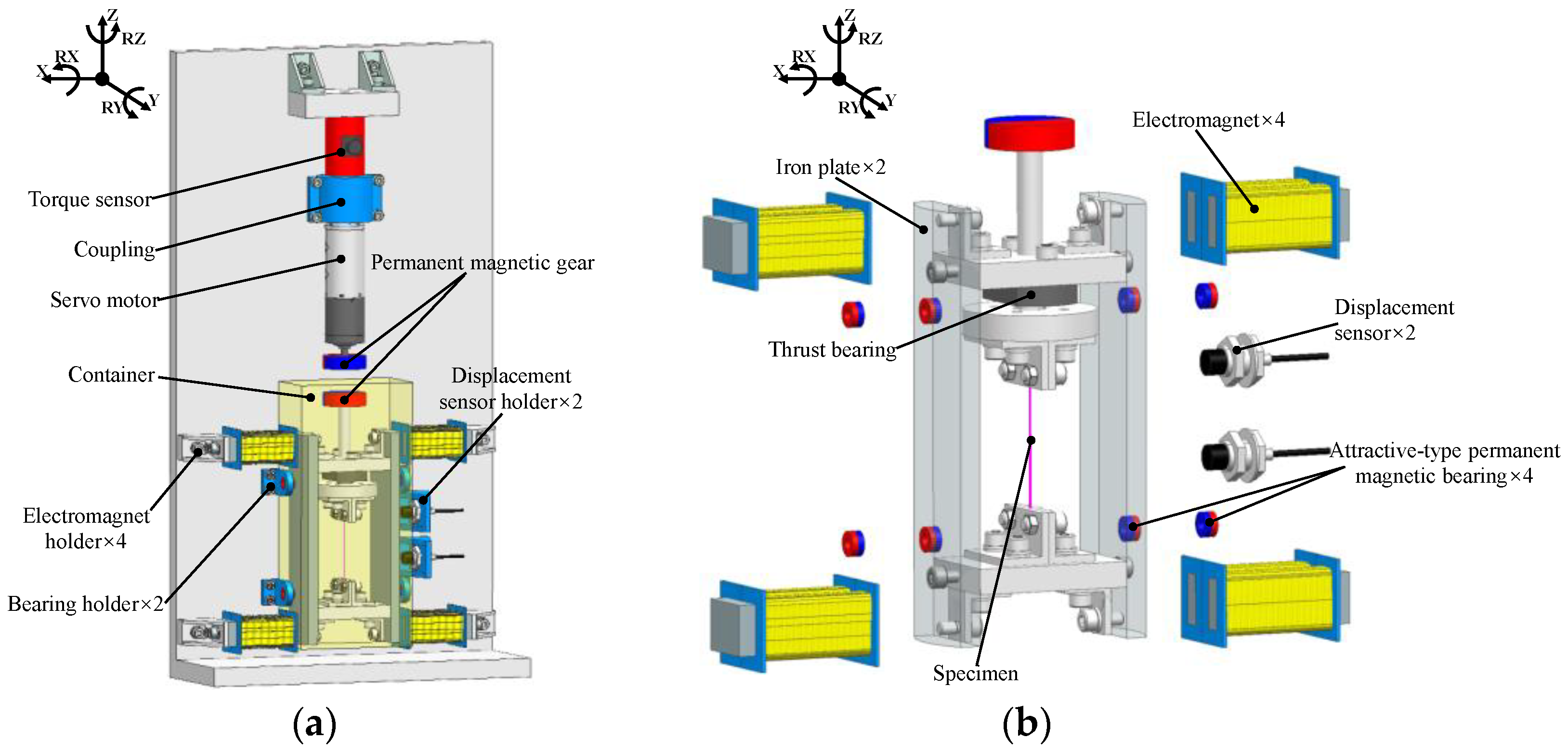
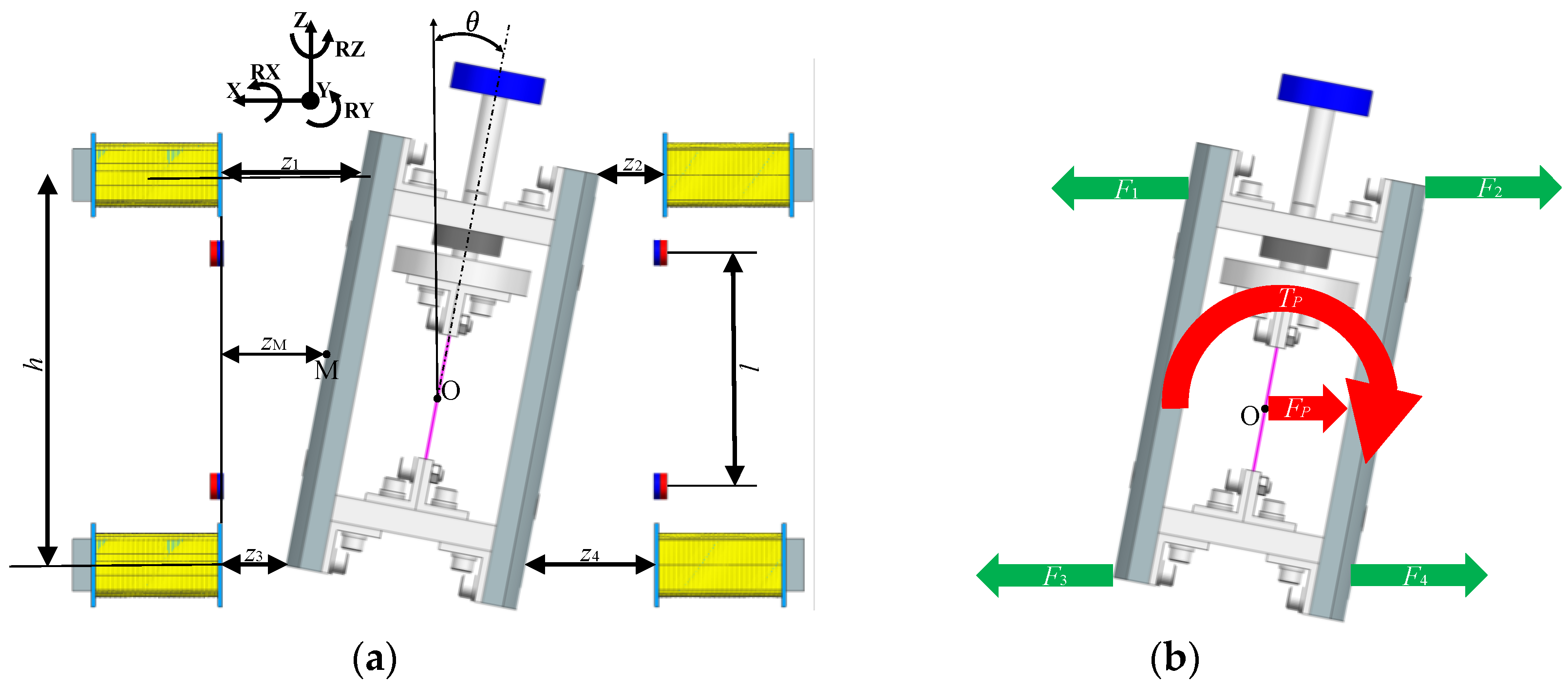
2.1. Structure Overview
2.2. Principle of Levitation
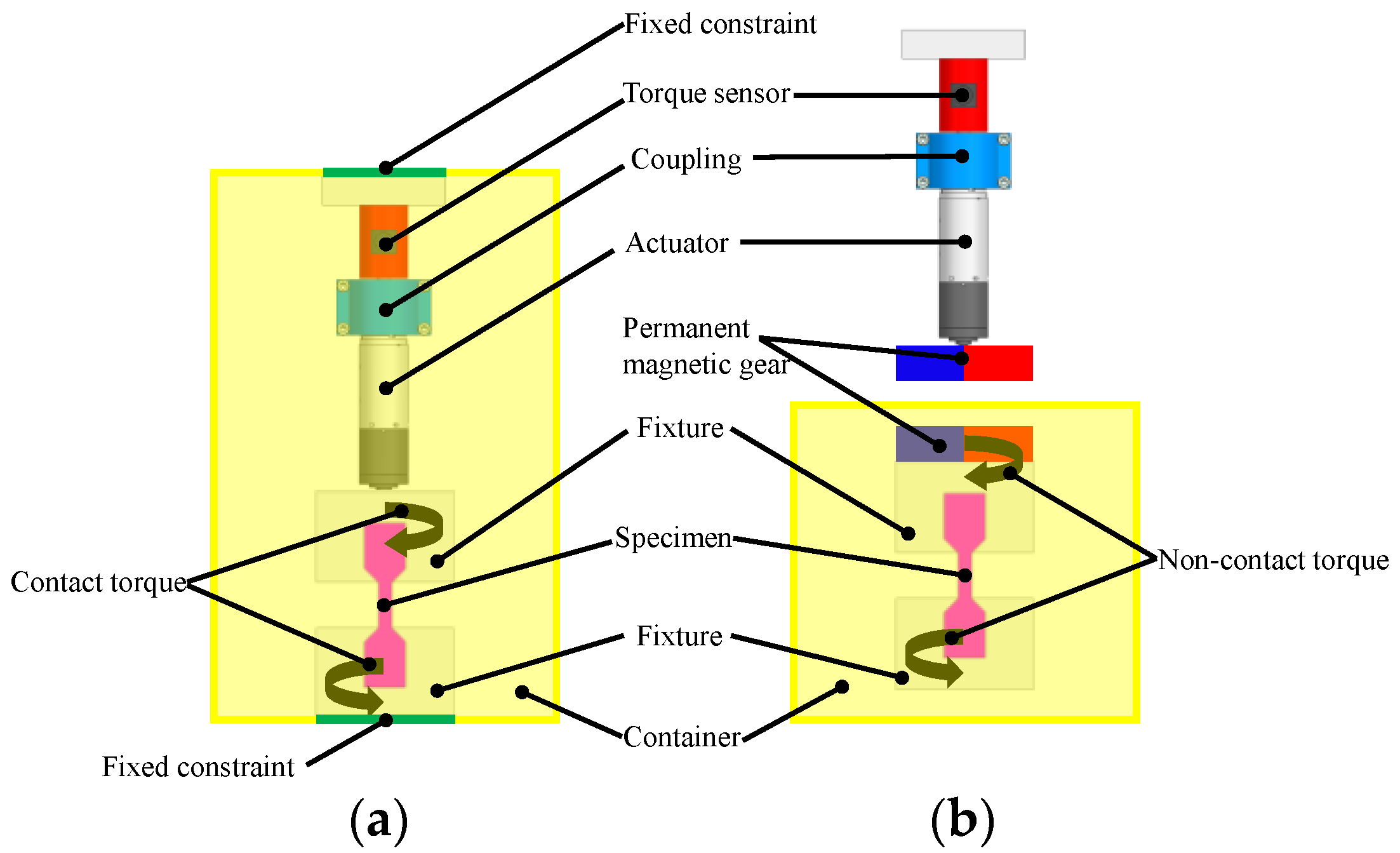
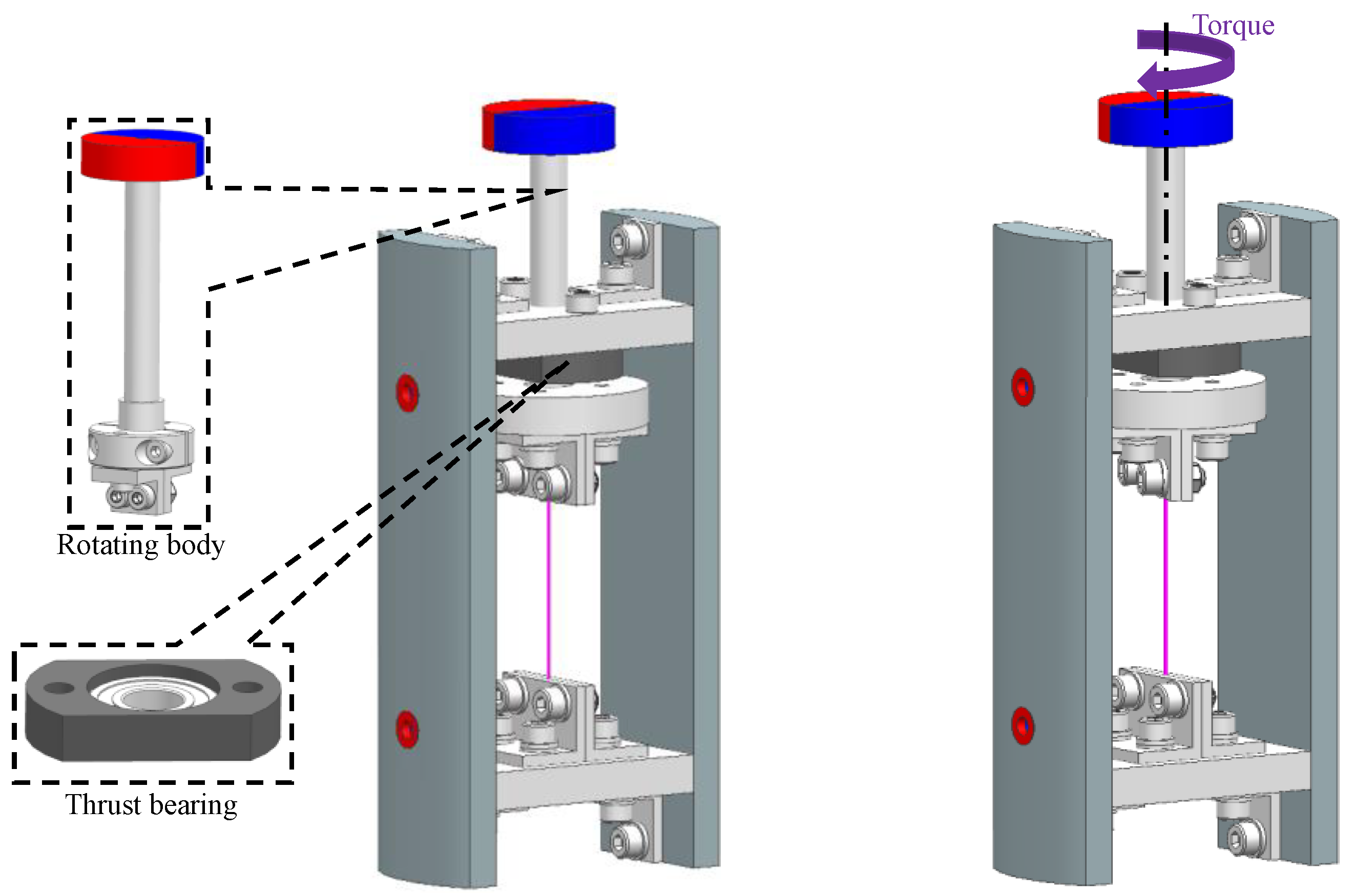
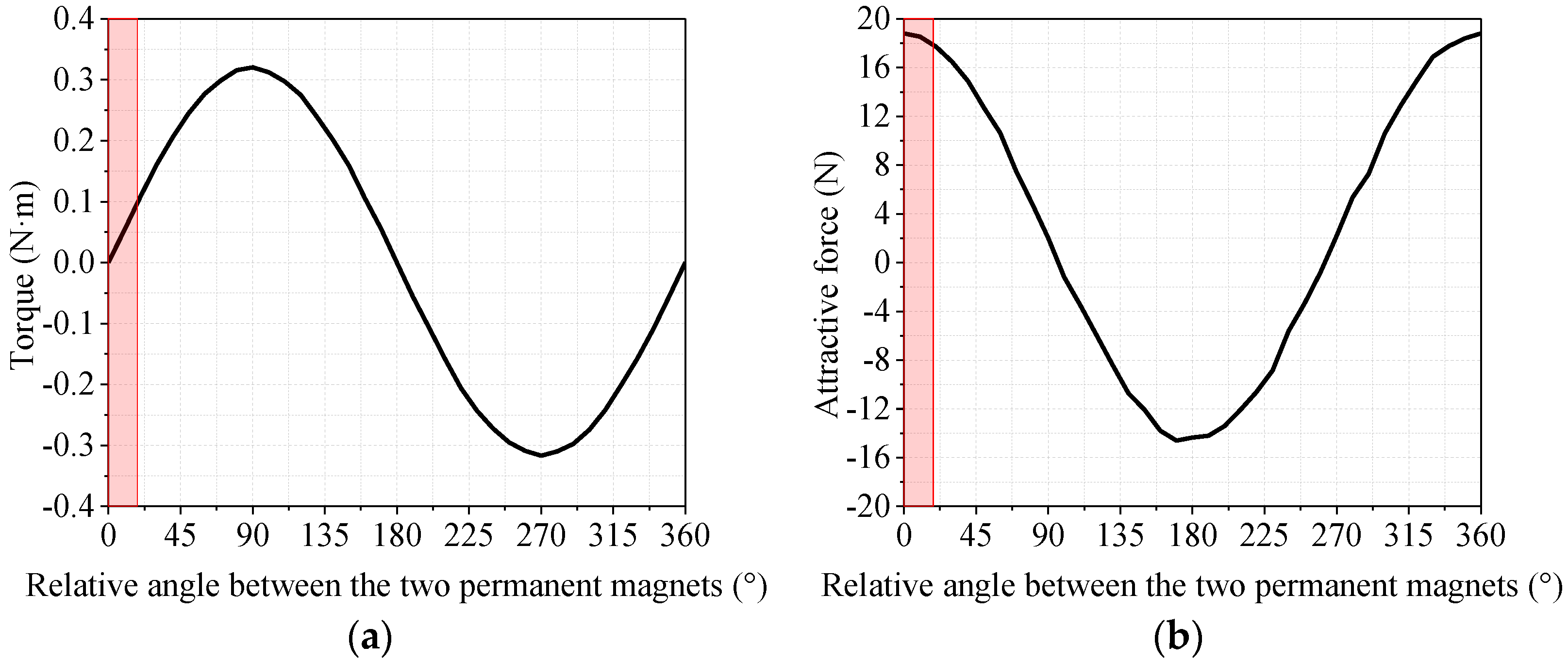
2.3. Principle of Torque Application
3. Control of X and RY
3.1. Plant Model
3.1.1. State Space Model Derivation
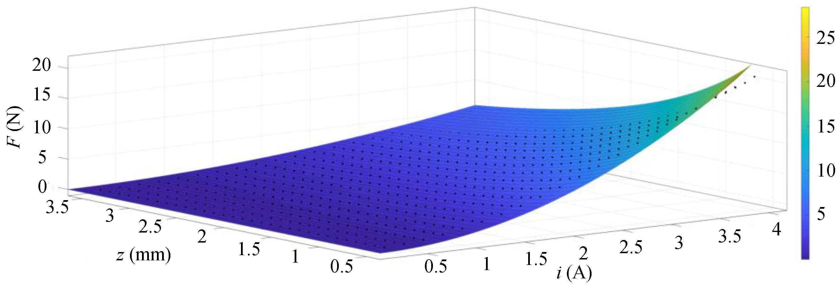
3.1.2. Determination of Plant Model Parameter
3.2. Control Design
3.3. Control Simulation
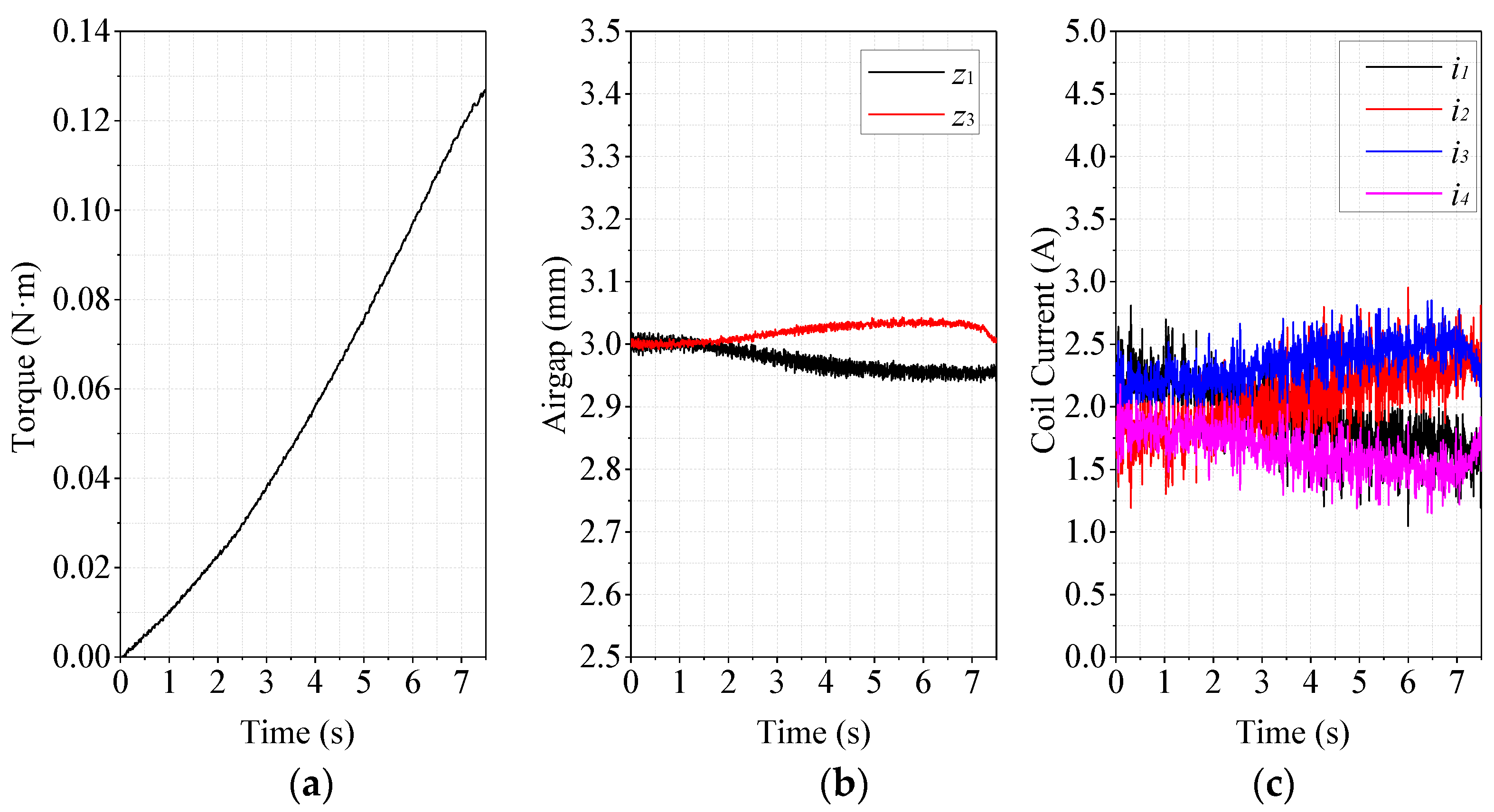
4. Experiment
5. Conclusions
Author Contributions
Funding
Data Availability Statement
Acknowledgments
Conflicts of Interest
Consent for Publication
References
- Yougang, S.; Haiyan, Q.; Junqi, X.; Guobin, L. Internet of Things-based online condition monitor and improved adaptive fuzzy control for a medium-low-speed maglev train system. IEEE Trans. Ind. Inform. 2019, 16, 2629–2639. [Google Scholar]
- Yonezu, T.; Watanabe, K.; Suzuki, E.; Sasakawa, T. Study on Electromagnetic Force Characteristics Acting on Levitation/Guidance Coils of a Superconducting Maglev Vehicle System. IEEE Trans. Magn. 2017, 53, 8300605. [Google Scholar] [CrossRef]
- Tanaka, K. Impacts of the opening of the maglev railway on daily accessibility in Japan: A comparative analysis with that of the Shinkansen. J. Transp. Geogr. 2023, 106, 103512. [Google Scholar] [CrossRef]
- Yuan, Y.; Li, J.; Deng, Z.; Liu, Z.; Wu, D.; Wang, L. Dynamic performance of HTS maglev and comparisons with another two types of high-speed railway vehicles. Cryogenics 2021, 117, 103321. [Google Scholar] [CrossRef]
- Deng, Z.; Wang, L.; Li, H.; Li, J.; Wang, H.; Yu, J. Dynamic studies of the HTS maglev transit system. IEEE Trans. Appl. Supercond. 2021, 31, 3600805. [Google Scholar] [CrossRef]
- Ke, H.; Lin, G.; Liu, Z. Prediction Approach of Negative Rail Potentials and Stray Currents in Medium-Low-Speed Maglev. IEEE Trans. Transp. Electrif. 2022, 8, 3801–3815. [Google Scholar]
- Yamagishi, K. Optimum Design of Integrated Magnetic Bearing Using Multiple HTS Bulk Units. IEEE Trans. Appl. Supercond. 2019, 29, 6801505. [Google Scholar] [CrossRef]
- Sugimoto, H.; Uemura, Y.; Chiba, A.; Rahman, M.A. Design of Homopolar Consequent-Pole Bearingless Motor with Wide Magnetic Gap. IEEE Trans. Magn. 2013, 49, 2315–2318. [Google Scholar] [CrossRef]
- Liu, Z.; Chiba, A.; Irino, Y.; Nakazawa, Y. Optimum pole number combination of a buried permanent magnet bearingless motor and test results at an output of 60 kW with a speed of 37000 r/min. IEEE Open J. Ind. Appl. 2020, 1, 33–41. [Google Scholar] [CrossRef]
- Cavalcante, R.G.; Fujii, Y.; Chiba, A. A bearingless motor with passive electrodynamic suspension in axial direction. IEEE Trans. Ind. Appl. 2021, 57, 6812–6822. [Google Scholar]
- Hemenway, N.R.; Gjemdal, H.; Severson, E.L. New three-pole combined radial–axial magnetic bearing for industrial bearingless motor systems. IEEE Trans. Ind. Appl. 2021, 57, 6754–6764. [Google Scholar] [CrossRef]
- Yunlei, J.; Torres, R.A.; Severson, E.L. Current regulation in parallel combined winding bearingless motors. IEEE Trans. Ind. Appl. 2019, 55, 4800–4810. [Google Scholar]
- Samiappan, C.; Mirnateghi, N.; Paden, B.E.; Antaki, J.F. Maglev Apparatus for Power Minimization and Control of Artificial Hearts. IEEE Trans. Control Syst. Technol. 2008, 16, 13–18. [Google Scholar] [CrossRef]
- Greatrex, N.; Kleinheyer, M.; Nestler, F.; Timms, D. The Maglev Heart. IEEE Spectr. 2019, 56, 22–29. [Google Scholar] [CrossRef]
- Xiao, Q.; Chen, W.; Ma, G.; Cui, F.; Li, S.; Zhang, W. Simulation of levitation control for a micromachined electrostatically levitated gyroscope. In Proceedings of the 4th IEEE International Conference on Nano/Micro Engineered and Molecular Systems, Shenzhen, China, 5 June 2009. [Google Scholar]
- Yang, W.M.; Chao, X.X.; Ma, J.; Li, G.Z. A spacecraft model flying around a levitated globe using YBCO bulk superconductors. J. Supercond. Nov. Magn. 2010, 23, 1391–1394. [Google Scholar] [CrossRef]
- Takeshi, M.; Takasaki, M.; Ishino, Y. Lateral vibration attenuation by the dynamic adjustment of bias currents in magnetic suspension system. J. Phys. Conf. Ser. 2016, 744, 012005. [Google Scholar]
- Sun, F.; Pei, W.; Zhao, C.; Jin, J.; Xu, F.; Zhang, X. Permanent Maglev Platform Using a Variable Flux Path Mechanism: Stable Levitation and Motion Control. IEEE Trans. Magn. 2022, 58, 8300410. [Google Scholar] [CrossRef]
- Zhu, Z.; Ni, Y.; Shao, L.; Jiao, J.; Li, X. Multiobjective optimization design of spherical axial split-phase permanent maglev flywheel machine based on kriging model. IEEE Access 2022, 10, 66943–66951. [Google Scholar] [CrossRef]
- Zhang, Z.; Gao, T.; Qin, Y.; Yang, J.; Zhou, F. Numerical study for zero-power maglev system inspired by undergraduate project kits. IEEE Access 2020, 8, 90316–90323. [Google Scholar] [CrossRef]
- Lei, C.; Guo, J.; Zhu, B.; Zhang, Z. Electronic nonlinearity of full-bridge PWM inverter for zero-power PEMS system. IEEE Access 2022, 10, 37670–37677. [Google Scholar]
- Ren, M.; Oka, K. Design and Analysis of a Non-Contact Tension Testing Device Based on Magnetic Levitation. IEEE Access 2022, 10, 19312–19332. [Google Scholar] [CrossRef]
- Ren, M.; Oka, K. Fixed Stiffness-Damping Control of a Magnetic Levitation Bending Testing Device. In Proceedings of the IEEE/ASME International Conference on Advanced Intelligent Mechatronics, Sapporo, Japan, 25 August 2022. [Google Scholar]
- Wan, H.; Kong, L.; Yang, B.; Xu, B.; Duan, M.; Dai, Y. Zone melting under vacuum purification method for high-purity aluminum. J. Mater. Res. Technol. 2022, 17, 802–808. [Google Scholar] [CrossRef]
- Kumar, C.; Sarangi, S. Dynamic behavior of self-acting gas-lubricated long journal bearing. Mech. Res. Commun. 2022, 124, 103950. [Google Scholar] [CrossRef]
- Jin, M.; Wei, Z.; Meng, Y.; Shu, H.; Tao, Y.; Bai, B.; Wang, X. Silicon-based graphene electro-optical modulators. Photonics 2022, 9, 82. [Google Scholar] [CrossRef]
- Tada, N.; Masago, H. Remotely-controlled tensile test of copper-cored lead-free solder joint in liquid using permanent magnet. In Proceedings of the 8th International Microsystems, Packaging, Assembly and Circuits Technology Conference, Taipei, Taiwan, 22–25 October 2013. [Google Scholar]
- Samuel, E. On the nature of the molecular forces which regulate the constitution of the luminiferous ether. Trans. Camb. Philos. Soc. 1848, 7, 97. [Google Scholar]
- Hui, Q.; Zheng, H.; Qin, W.; Zhang, Z. Lateral vibration control of a shafting-hull coupled system with electromagnetic bearings. J. Low Freq. Noise Vib. Act. Control 2019, 38, 154–167. [Google Scholar]
- Wang, F.; Zhang, L.; Feng, X.; Guo, H. An Adaptive Control Strategy for Virtual Synchronous Generator. IEEE Trans. Ind. Appl. 2018, 54, 5124–5133. [Google Scholar] [CrossRef]


| Name | Material/Model | Number |
|---|---|---|
| Torque sensor | Forsentek FT05 | 1 |
| Servo motor | Maxon A-max 32 | 1 |
| Displacement sensor | Panasonic GP-XC12ML | 2 |
| Permanent magnetic gear | N40 | 1 |
| Attractive-type permanent magnetic bearing | N40 | 4 |
| Degree of Freedom | Control Type | Component That Implements Control |
|---|---|---|
| X | Active | The four electromagnets |
| Y | Passive | The four attractive-type permanent magnetic bearings |
| Z | Passive | The four attractive-type permanent magnetic bearings |
| RX | Passive | The four attractive-type permanent magnetic bearings |
| RY | Active | The four electromagnets |
| RZ | Passive | The four attractive-type permanent magnetic bearings |
| Parameter Name | Parameter Value |
|---|---|
| a (Nm2A−2) | 1.204 × 10⁻⁵ |
| c (mm) | 2.38 |
| i0 (A) | 2 |
| z0 (mm) | 3 |
| ki (N/A) | 1.6639 |
| kz (N/m) | 618.5426 |
| m (kg) | 1.731 |
| J (kg·m2) | 0.0033 |
| h (m) | 0.143 |
| l (m) | 0.0774 |
| Parameter Name | Parameter Value |
|---|---|
| P1 (A/m) | 9886 |
| D1 (A·s/m) | 64 |
| P2 (A/m) | 3166 |
| D2 (A·s/m) | 23 |
| Parameter Name | Parameter Value |
|---|---|
| i0 (A) | 2 |
| z0 (mm) | 3 |
| P1 (A/m) | 10,000 |
| I1 (A/m/s) | 1000 |
| D1 (A·s/m) | 50 |
| P2 (A/m) | 7000 |
| I2 (A/m/s) | 1000 |
| D2 (A·s/m) | 35 |
| Property Name | Property Value |
|---|---|
| Material | Z-ASA PRO |
| Length (mm) | 67 |
| Width (mm) | 6 |
| Thickness (mm) | 1.6 |
Disclaimer/Publisher’s Note: The statements, opinions and data contained in all publications are solely those of the individual author(s) and contributor(s) and not of MDPI and/or the editor(s). MDPI and/or the editor(s) disclaim responsibility for any injury to people or property resulting from any ideas, methods, instructions or products referred to in the content. |
© 2023 by the authors. Licensee MDPI, Basel, Switzerland. This article is an open access article distributed under the terms and conditions of the Creative Commons Attribution (CC BY) license (https://creativecommons.org/licenses/by/4.0/).
Share and Cite
Ren, M.; Oka, K. Design of a Noncontact Torsion Testing Device Using Magnetic Levitation Mechanism. Actuators 2023, 12, 174. https://doi.org/10.3390/act12040174
Ren M, Oka K. Design of a Noncontact Torsion Testing Device Using Magnetic Levitation Mechanism. Actuators. 2023; 12(4):174. https://doi.org/10.3390/act12040174
Chicago/Turabian StyleRen, Mengyi, and Koichi Oka. 2023. "Design of a Noncontact Torsion Testing Device Using Magnetic Levitation Mechanism" Actuators 12, no. 4: 174. https://doi.org/10.3390/act12040174
APA StyleRen, M., & Oka, K. (2023). Design of a Noncontact Torsion Testing Device Using Magnetic Levitation Mechanism. Actuators, 12(4), 174. https://doi.org/10.3390/act12040174