Abstract
In this paper, we propose a novel method for planning grinding trajectories on curved surfaces to improve the grinding efficiency of large aluminum alloy surfaces with welds and defect areas. Our method consists of three parts. Firstly, we introduce a deficiency positioning method based on a two-dimensional image and three-dimensional point cloud, which enables us to accurately and quickly locate the three-dimensional defective areas. Secondly, we propose a 2D weld positioning method based on the defect area and obtain the spatial position of the 3D weld by combining the relationship between 2D and 3D images. Additionally, we propose an orthogonal projection method from the point cloud to the aluminum alloy surface to calculate the weld reinforcement. Thirdly, we present a space spiral grinding trajectory planning method for complex curved surfaces based on the characteristics of the weld reinforcement, spatial position, and spatial position information of the defect area. This method shortens the grinding time of the defect area and improves efficiency. Simulation and experimental results show that our grinding trajectory planning method is more efficient than other grinding methods in removing defects from the surface of aluminum alloys. Moreover, the defect area after grinding is smoother than before.
1. Introduction
In the manufacturing process of aerospace devices, welding technology is often utilized for assembly to create high-strength and stable structures, ensuring the safety of spacecraft in complex environments. The use of lightweight structures produced by aerospace welding reduces the weight of the spacecraft, improving its motion efficiency and increasing its durability to withstand extreme conditions, thus extending its service life.
Aerospace welding is an essential component in aerospace engineering and plays a crucial role in ensuring the safe and efficient operation of spacecraft. However, during the process, welding bumps and other defects may occur due to improper welding parameters, material issues, or environmental factors such as temperature, humidity, and air flow.
To eliminate these welding bumps and defects, grinding is a common and effective method. By doing so, the safety and precision of aerospace devices are improved and the service life of aerospace components is increased, as weld flashes and defects can otherwise reduce their lifespan.
Aluminum alloy is a crucial material used in the manufacturing of aerospace devices. It boasts good strength, hardness, corrosion resistance, and thermal stability, making aerospace aluminum alloy surfaces ideal for creating aerospace device shells and structural components, particularly in high-tech applications that require high strength and thermal stability, such as satellites and rockets. As a result, aluminum alloy surface grinding is of immense value in the aerospace industry.
Traditional manual grinding involves grinding and smoothing aerospace devices by hand, and it typically requires skilled technicians and a lot of time and effort. Furthermore, the accuracy of manual grinding can be influenced by human factors, making it challenging to ensure sufficient precision. With technological advancements, modern aerospace technology has increasingly adopted mechanized and robot-automated grinding technology. Robot-automated grinding is faster, more accurate, and safer than traditional manual grinding, making it an inevitable trend in the use of robots for the automatic grinding of aerospace devices.
Ge et al. [1] developed seam tracking software and applied an online interaction method for grinding system data. They also proposed and constructed an online automatic welding seam grinding system based on laser vision sensors. In their later work, Ge et al. [2] built an efficient automatic welding seam grinding system based on model segmentation and proposed a new simple and efficient welding seam extraction algorithm. They planned the grinding path of the robot, which can extract different seams, achieve a regular weld profile, and increase grinding efficiency by 50%. Zhao [3] proposed a mobile robotic grinding system for large workpieces that can move in large spaces. The system does not require an accurate CAD model of the workpiece and achieves better machining accuracy and automatic grinding work, suitable for different continuous surfaces. Zhang [4] developed a robotic automatic grinding system to achieve high-quality grinding of aerospace blades. They proposed a hybrid force/position anti-disturbance control strategy based on fuzzy PID control for the automatic grinding system. This has great potential in achieving excellent surface quality and high grinding efficiency of aviation blades. Furthermore, the proposed method is general and can be applied to robotic automatic grinding of other types of inserts or workpieces. Yu [5] developed a robotic grinding system with a novel active end effector for grinding complex PMMA parts with high surface integrity. The proposed robotic grinding system can strictly control the normal contact force and ensure the PMMA parts’ high surface integrity. Freeform surfaces have important applications in various industrial fields. However, achieving a high level of surface finish on freeform surfaces using grinding is always a challenging task. Xu [6] proposed a new custom hybrid robot for freeform surface grinding to replace the traditional computer numerical control (CNC) machine. Wang [7] proposed an automatic grinding system with a fast and accurate robot grinding path planning method for automatic removal of free-form surface irregular weldments. Aiming at complex features such as weak contrast, uneven light, and scarcity in industrial environments, Wan [8] proposed a grinding workstation composed of machine vision and industrial manipulators to solve the problems of positioning and automatic grinding of rough metal castings. The system has high accuracy and efficiency and can well overcome the influence of grinding workpiece material, scratches, rust, and other factors. Ding [9] proposed a robotic grinding system for grinding complex concave cavity surfaces to improve the quality of automatic grinding of curved surfaces by industrial robots and ensure constant grinding pressure during the grinding process. The proposed system can achieve stable force control and precise position control and is easy to implement online, ensuring a uniform removal rate of surface material at different normal vectors.
In addition, Zhang [10] proposed a system for robots to automatically grind workpieces conveyed on abrasive belts, enabling robots to grind workpieces without collisions, and Qiu [11] proposed four grinding systems based on robot-based blade surface grinding schemes. Xie [12] proposed an automatic grinding system for metal products, using a force-controlled grinding robot instead of manually grinding metal. Zhou [13] proposed an automatic grinding robot based on an adaptive impedance control strategy system. Liu [14] proposed a robot system for automatic grinding on free-form surfaces, effectively reducing the surface roughness. Tian et al. [15] proposed a curved-surface robot automatic grinding system which mainly grinds free-form surfaces, such as curved steel mold parts and other fields related to mold finishing, effectively reducing surface roughness. Tian et al. [16] also proposed that the platform can be controlled independently, automatically, and in real-time during the grinding process of the automatic grinding system to achieve ultra-precision, high-efficiency, and low-cost surface grinding. Lin et al. [17] designed a robotic grinding system with adaptive force control. The system controller is stable, can quickly eliminate external force disturbance, and can effectively perform precise grinding with adaptive force control. Kharidege et al. [18] proposed an automatic grinding system based on an automatic planning and programming system based on CAD system data for creating robot paths and grinding the use of free-form workpiece surfaces.
Existing robot grinding systems can be broadly classified into two types: automatic grinding systems based on workpiece CAD model data and automatic grinding systems based directly on point cloud data. However, regardless of the type of system used to grind the workpiece, the core function is the automatic generation of robotic machining paths. The most commonly used strategy for robot grinding path planning is based on the CAD model of the workpiece [19,20,21]. However, in many cases, an accurate CAD model cannot be obtained or some deformation of the workpiece during use is quite different from the initial CAD model. Therefore, it is necessary to establish the CAD model of the object using reverse engineering. Morozov et al. [22] used reverse engineering to reconstruct the CAD model of the aircraft wing mask and generated the scanning trajectory of non-destructive testing through software. Ge [1] used a laser scanner sensor to scan the weld with workpiece defects, reconstructed the 3D model of the workpiece, and performed path planning based on it. Wang [7] first obtained the point cloud of the workpiece surface, generated the parent surface, added the weld seam to the surface to generate the CAD model of the workpiece through the superposition method, and imported the obtained CAD model into the offline simulation system to obtain the grinding path of the weld seam. The calculation of the point cloud using the method of reverse engineering is large and time-consuming.
The information contained in point clouds can effectively reflect the surface characteristics of a workpiece to be measured, and as such, many researchers process point cloud data directly to achieve robot trajectory planning. Some studies, such as [23,24,25,26], utilize the obtained workpiece point cloud data for path planning to grind the entire workpiece surface. Yang [27] proposed a three-dimensional weld grinding path planning method based on point clouds, and Geng [28] proposed a point-based, cloud-based automatic welding path planning method for steel mesh.
Most trajectory planning methods based on point clouds use plane and point cloud data to slice and obtain the trajectory of the workpiece surface. For example, Ge et al. [24] generated grinding paths by creating a series of planes that intersect the target surface, computing intersection lines from point cloud data with the planes, and using local plane fitting to estimate normals at contact points. Zhang et al. [26] measured the workpiece surface with a 3D sensor to obtain point cloud data, and obtained the trajectory of the workpiece surface by slicing the preprocessed point cloud data. Yu et al. [29] used a slicing algorithm to process the free-form surface of the painting robot, intercepted the point cloud model with multiple parallel slices to obtain the cross-section contour points, and achieved trajectory planning of the painting robot. D Gleeson et al. [30] also used the trajectory planning method of switching directions in parallel to achieve spraying. Chen et al. [25] obtained section polylines after acquiring slices and processing section data of the workpiece point cloud model, performed average sampling of section polylines, estimated normal vectors of all sampling points, and used an interpolation algorithm to connect the data points to obtain the spatial trajectory of the spraying robot. In the field of trajectory planning for spray painting robots, Trigatti [31] proposed an innovative trajectory planning algorithm with the aim of limiting the velocity and acceleration of the robot. To achieve better performance of hybrid robots affected by nonlinear dynamics and friction, Zhang [32] studied an accurate method for dynamic modeling and control parameter design. However, they did not consider the efficiency of the trajectory itself. Ren et al. [23] used the slicing algorithm to directly generate the grinding path planning of the point cloud data, and streamlined it according to the curvature of the workpiece area, which better preserved the characteristics of the point cloud data and improved the accuracy of path planning. Although the existing methods that use the slicing approach for path planning on the workpiece surface can achieve automatic grinding of flat or simple curved surfaces, they may cause frequent entry and exit of the grinding tool. Similar to robot polishing, the field of trajectory planning for spraying has not considered the requirement of efficient and continuous grinding.
In conclusion, the current point cloud-based methods for trajectory planning of complex surface polishing are inefficient. This paper proposes a novel method for automatic aluminum alloy surface grinding trajectory planning of industrial robot based on weld seam recognition and positioning. The method is divided into three main parts. Firstly, in the defect positioning process, unlike other direct point cloud-based methods, this paper proposes a high-speed and high-precision defect positioning method that combines 2D images with 3D point clouds. Secondly, unlike most methods that use expensive laser measurement instruments to locate defects and measure the height differences on the surface of welds, the proposed method only uses a depth camera for locating the spatial position of welds based on 2D seam recognition and 3D point clouds. Additionally, a method based on orthogonal projection is proposed to extract the weld bead height, providing crucial information for polishing the weld bead until it is level with the surrounding base material. Thirdly, a novel spatial helical grinding trajectory planning method is proposed for defect areas on complex curved surfaces, providing efficient and continuous grinding trajectories for the robot to polish aluminum alloy defect areas.
2. The Overall Flow of the Grinding Trajectory Planning Algorithm
Figure 1 depicts the scene of grinding a large aluminum alloy surface. The aim of this paper is to grind both the weld reinforcement and defect areas. The overall process of the proposed grinding trajectory planning algorithm is illustrated in Figure 2. Firstly, the defect area, identified as part 1, must be located. Next, it needs to be determined whether any weld reinforcement needs to be grinded. If any weld reinforcement is present, the weld position should be located and the information about the weld reinforcement extracted to plan the weld grinding trajectory, which is part 2. Alternatively, if there is no weld reinforcement, the grinding trajectory for the weld defect area should be planned directly, which is part 3.
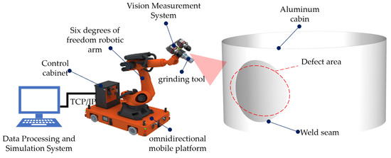
Figure 1.
Schematic diagram of large aluminum alloy cabin grinding.
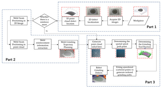
Figure 2.
The overall flow of the grinding trajectory planning algorithm.
3. Defect Area Positioning
In the methods for 3D defect localization, most of them adopt the direct point cloud-based method. However, compared to the method based on the combination of 2D and 3D, the direct point cloud calculation is more complex and time-consuming. To more quickly and accurately locate the defect position, we first precisely locate the defect position in the 2D image using grayscale image processing. The purpose of applying grayscale to images is to smooth rough edges and reduce noise, and one of the fastest methods in image segmentation is image thresholding. The grayscale image is used as the input image, and the threshold is set based on the gray value difference between the defect area and other areas in the grayscale image. A binary image is then generated, and erosion and dilation morphological operators are used to separate the weld boundary and locate the defect area. The process is depicted in Figure 3.
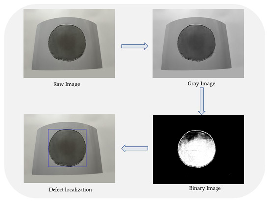
Figure 3.
Flowchart of 2D defect area location.
The selection of the threshold is a decisive factor affecting the binarization results in the binarization process of grayscale images. Currently, there is no generally accepted theoretical parameter selection method, and most of them are based on experience or manual selection of threshold parameters. In this paper, based on the statistical method, we calculate the gray histogram of the gray image, as shown in Figure 4, and select the most concentrated gray range as the binarization threshold parameter according to the normal distribution theory. This allows for automatic selection of experimental theoretical parameters without requiring manual intervention.
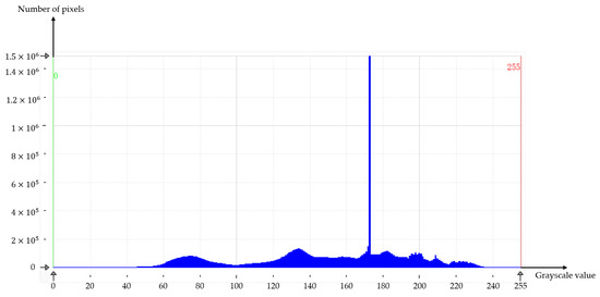
Figure 4.
Gray histogram.
The point cloud is a collection of 3D points that represent the shape and structure of a scene. Each point in the point cloud is represented by its x, y, and z coordinates, which denote its position in 3D space. The conversion of a depth image into a point cloud is achieved by using the depth value of each pixel in the depth image to calculate the 3D coordinates of the corresponding point in the point cloud.
The steps in Figure 1 are used to obtain the defect area in the two-dimensional image. If a point, , in the defect area is assumed, its depth pixel coordinates, , can be determined, where d is the depth distance. The relationship between and its spatial point cloud coordinates, , is shown in Figure 5 and expressed as follows:
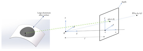
Figure 5.
Correspondence between depth map and point cloud.
Among them, , are the focal length of the camera on the x and y axes, , are the aperture center of the camera, and s is the scaling factor of the depth map. Define the four parameters , , , as matrix C:
The matrix equation of each point Q in the space corresponding to the q coordinate of each pixel in the defect area in the depth map is as follows:
This paper differs from the method of directly locating defect areas based on the point cloud. Instead, it uses the results of two-dimensional defect location to retain the depth pixels within the defect area to generate three-dimensional data, while filtering out depth pixels outside the area, as shown in Figure 6.
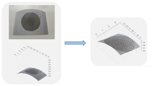
Figure 6.
2D image mapping 3D point cloud.
4. Weld Feature Extraction
In contrast to ordinary complex surfaces, the trajectory planning for welding seams and defect area grinding of large aerospace devices must consider the presence of weld seams. To ensure the accuracy of weld feature extraction, the first step is to obtain its position information. A common method is to extract the edge information of the weld in the point cloud using the curvature of the weld part and sudden changes in surface curvature for segmentation processing, but this method incurs a large error and calculation. The two-dimensional weld location method based on defect areas proposed in this paper quickly obtains the point cloud coordinates of the weld location.
In practice, the presence of weld reinforcement prevents direct grinding of the defect area. To efficiently grind the curved surface’s defect area, it is necessary to grind the weld reinforcement to the same height as the parent surface. Thus, it is necessary to extract weld seam feature information from the complex surface. The welds on many workpieces cannot be completed in a single grinding process and typically require multiple grinding passes. After each pass, the maximum height of the weld reinforcement must be measured, and the grinding feed rate must be corrected mid-way based on the remaining height. As a result, extracting the weld reinforcement features before grinding is an essential step each time.
Edge detection is a technique in computer vision that identifies edges, or changes in color or grayscale, in an image. It can be used for various purposes, including image segmentation, object recognition, and image compression. Common edge detection algorithms include Canny, Sobel, and Laplacian edge detection. Canny edge detection is widely used in defect detection due to its high efficiency, precision, and fault tolerance.
In practice, object boundaries can interfere with the Canny operator when only the edge of the weld is required. This paper proposes a weld spatial location based on the defect area to resolve this issue. By filtering out the non-defect area and retaining only the edge of the defect area, the edge of the weld can be obtained quickly and accurately, as shown in Figure 7. The three-dimensional coordinates of the welding seam can be obtained by solving the Formula (5) and finding the location of the three-dimensional space of the weld in the point cloud.
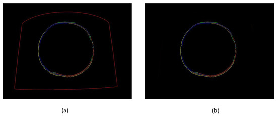
Figure 7.
Comparison of two-dimensional weld positioning effects based on Canny and defect regions. (a) Edge detection results based on Canny operator. (b) Weld extraction result map based on defect area.
For the projection of a point to a two-dimensional curve, as shown in Figure 8, we assume that is a two-dimensional curve in space, and p is a test point. According to the idea of Newton’s iterative method, the geometric iteration of calculating the projection point of p on the curve is as follows: Project p onto the tangent at , and obtain a value that can be represented by and its derivative point :
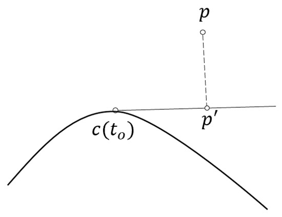
Figure 8.
Schematic diagram of point projection on curve.
The scalar product of x, y vectors we denote as , and the norm of a vector x we denote as , we get the following:
We update by increasing , and repeat the above steps until is less than a given tolerance or the angle is close enough to 90 degrees, so that we can calculate p on the curve projection.
We extend the geometric iteration described above to large aluminum alloy surfaces in 3D space. The partial derivatives with respect to the parameters and are denoted by , etc.
In order to calculate the projection of the weld onto the aluminum alloy surface, we project a point on the weld onto the surface, as shown in Figure 9. Given an initial guess of , we find by projecting p onto the tangent plane at :
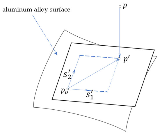
Figure 9.
Schematic diagram of point projection on surface.
By multiplying both sides by , we get the following:
By multiplying both sides by , we get the following:
Therefore, and can be solved as the solution of a system of regular linear equations with a coefficient matrix . We update by adding and and repeating the above steps until the line between the projected point and the point cloud is perpendicular to the aluminum alloy surface and the projection distance between the point and the point cloud is equal to the height of the weld.
5. Grinding Trajectory Planning for Complex Surface Defect Area
For grinding flat workpieces, only two-dimensional movements in the x and y directions within the workpiece plane are necessary, with the bottom of the grinding tool kept perpendicular to the workpiece plane. As a result, only grinding path planning in the x and y directions is required. The main method of road force planning for planar workpiece grinding is parallel grinding, specifically the grinding in one direction in parallel and the grinding in which the direction is switched back and forth. The schematic diagram is shown in Figure 10.
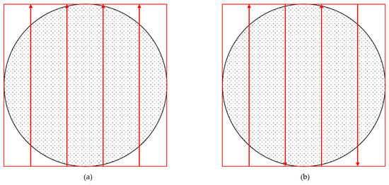
Figure 10.
Parallel grinding method for flat workpieces, (a) is grinding parallel to one direction, (b) is parallel grinding with switched directions.
Most current methods for generating toolpaths on surface point clouds still primarily use slices to create parallel grinding trajectories. The ultimate goal of grinding trajectory planning is to design the most appropriate tool path topology in the shortest processing time to achieve a good surface quality. Ideally, a part should be machined in a continuous fashion, with as few path interruptions or air cuts as possible for maximum cutting efficiency. As a result, smooth toolpaths without rapid retracts and direction changes are preferred, such as helical toolpaths.
The Archimedean spiral is an infinite planar geometric shape that starts from the center and spirals outward continuously, as shown in Figure 11. For flat workpieces, the Archimedean spiral is a good grinding form because it allows for a grinding path with continuous motion, no need for reversing, and smooth changes. The Archimedean spiral is a locus of points corresponding to the position of a point away from a fixed point along a line of constant angular velocity. In polar coordinates , it can be described as:
where a represents the distance from the center of the circle, and b represents the angle, described in the Cartesian coordinate system as:
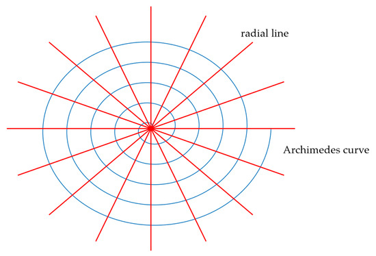
Figure 11.
Plane Archimedes spiral.
The Archimedean spiral lies on a plane and can be parameterized with two parameters r and , as in Formulas (11) and (12). According to Equation (11), given a constant , a set of parametric curves, which are circles, can be obtained. Given a constant , another set of parametric curves, which are radial, can be obtained. For ease of notation, we will refer to these circles as “latitudes” and the radial direction as “longitudes.” The two sets of curves are orthogonal at their point of intersection.
The intersection of a radial line and the Archimedes curve is a plane path point, and the distance between adjacent intersection points of the same radial line and the spiral line is equal. On a plane, as shown in the left figure of Figure 12, n) represents the intersection point between the radial spiral and the Archimedes spiral. After deformation, the distances between and are equal, i.e., or . For large-scale aluminum alloy surfaces, the method of projection and back-projection can be used directly. That is, the Archimedes spiral grinding path is first planned on the plane and then back-projected onto the 3D point cloud to plan the grinding path of the surface. When the surface slope increases, the projection distance between two adjacent channels of the spiral increases, as shown in the right figure of Figure 12. , but on the radial curve in space, especially when the normal of the surface is perpendicular to the projection direction. In this case, the distance between two adjacent channels, namely and , is infinite.
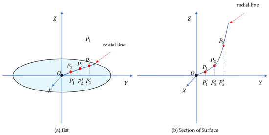
Figure 12.
Schematic diagram of the distance between adjacent points in the radial direction, (a) radial line on plane, (b) radial lines on surface.
Based on the idea of the planar Archimedes spiral, this paper proposes a method for planning the grinding trajectory of helices on complex surfaces. The core idea of the method is to ensure that the arc lengths of adjacent points in the radial direction of the helix on the surface are equal. In the right figure of Figure 12, it is shown that . In order to perform uniform sampling on the spatial radial line, radial curves are first constructed in all directions on the surface point cloud. The spacing between the helices is assumed to be , and each radial curve is uniformly sampled according to its arc length parameter , where is the total arc length of the i-th radial curve. These sampling points are then interpolated with a helical curve to generate the helical toolpath. Currently, some people, such as Xu et al. [33], use the trajectory planning method of spiral grinding. However, the method they use to obtain the spatial spiral trajectory involves projection and back-projection, which makes the process more complex and time-consuming. As a result, it may not be suitable for real-time grinding systems.
It is hard to obtain a parametric analytical expression of the radial arc length on the surface. In this study, the slicing method is used to find the radial curves at the intersection of the point cloud plane and slices in each direction, as illustrated in Figure 13. Numerical integration is then utilized to determine the arc length between the point cloud data, using the distance between adjacent points in the radial point cloud as the arc length between two points. A specified arc length spacing Ns is used, with the center point of the defect area serving as the center of the spiral line. The radial curve in each direction is obtained through the slicing method and a grinding point on the radial line is selected based on the distance from the specified arc length spacing, as shown in Figure 14.
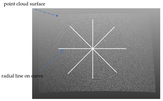
Figure 13.
Radial line graph on the point cloud curve surface.
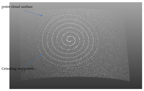
Figure 14.
Grinding trajectory points on the point cloud surface.
6. Simulation Experiment and Result Analysis
A robot grinding platform is established in the RoboDK simulation environment, as shown in Figure 15.
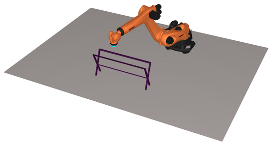
Figure 15.
The grinding platform.
Based on the orthogonal projection method proposed in Section 3, the highest distance of the weld is extracted and the data obtained are shown in Figure 16.
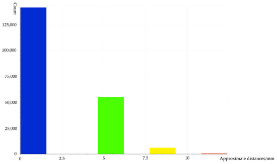
Figure 16.
Statistical diagram of distance from point to surface.
Through the robot automatic grinding aluminum alloy profile trajectory planning algorithm using weld recognition and positioning, the trajectory points of weld residual height grinding and the trajectory points of point cloud surface defect area grinding were obtained. The trajectory points for spiral grinding in the defect area have been obtained through the ICP registration of the point cloud file and the STereoLithography (STL) file of the aluminum alloy surface model, and the grinding trajectory points on the aluminum alloy surface model have been obtained. The three-dimensional coordinates and normal vectors of these points have been imported into RoboDK, where they have been connected to form the grinding trajectory, shown in Figure 17, Figure 18, Figure 19 and Figure 20. Figure 17, Figure 18, Figure 19 and Figure 20 show the grinding track of the weld reinforcement, the grinding process of the weld reinforcement, the spiral grinding trajectory of the defect area, and the grinding process of the defect area, respectively.
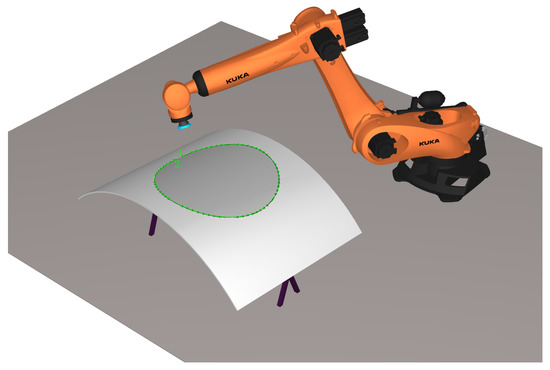
Figure 17.
The grinding track of the weld reinforcement.
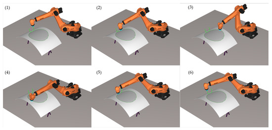
Figure 18.
The grinding process of the weld reinforcement.
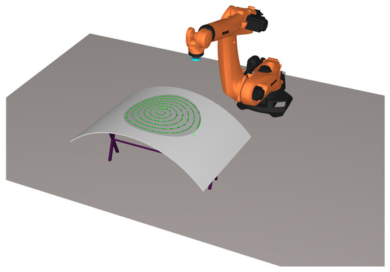
Figure 19.
The spiral grinding trajectory of the defect area.
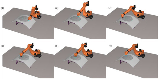
Figure 20.
The grinding process of the defect area.
The x-axis represents the distance from the point to the surface in millimeters and the y-axis shows the number of point clouds. Most of the point clouds are between 0 and 2.5 mm, which correspond to points on the surface, and the maximum weld reinforcement is 15 mm. The number of times the welding seam must be ground is determined based on the highest weld reinforcement until the height of the welding seam is equal to the surrounding height.
The time and efficiency of the parallel sanding trajectory and the sanding trajectory based on the isometric slicing method were compared through numerical experiments. Figure 21a,b show the parallel grinding trajectory in one direction and the grinding trajectory switching back and forth, respectively. It can be observed that the time required for parallel sanding in and out in one direction is much longer than the time required for parallel sanding in and out switching back and forth. The spiral sanding based on the curved surface only requires one tool in and out and continuous sanding without any pause. The sanding speed was set at 50 mm/s, 70 mm/s, 90 mm/s, and 110 mm/s, respectively, and the time taken to sand the entire defect area for each of the three sanding methods is shown in the Table 1. It can be seen that the time required for sanding based on the defective area algorithm is much less than that of the parallel sanding trajectory method and there is no need to enter and exit the tool and switch direction in the middle; thus, the sanding efficiency has been significantly improved.
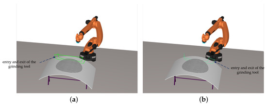
Figure 21.
The parallel grinding trajectory. (a) The parallel grinding trajectory in one direction. (b) The grinding trajectory switching back and forth.

Table 1.
Time Spent by Different Sanding Methods.
In this article, we use the KUKA robot as the simulation platform and the ESTUN robot for actual experimentation. Due to the difficulty in obtaining aerospace grinding workpieces, we only have one workpiece available for grinding, which prevents us from conducting repeated experiments with different grinding methods. Our objective in using the simulation platform is to verify the efficiency of the spiral grinding trajectory compared to other grinding trajectories and then use the spiral grinding method for actual grinding in the experiment. The experiment aims to demonstrate the correctness of the generated grinding trajectory.
Since the trajectory planning algorithm proposed in this paper is not dependent on the type of robot, it is applicable to multiple platforms. Although the simulation robot is different from the actual robot used in the experiment, this does not affect the final result.
Figure 22 illustrates the experimental platform used in this paper.
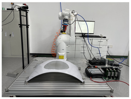
Figure 22.
The experimental platform.
We used the open-source ARIS library [34], developed by our team, as the basis for controlling the robotic arm’s hardware. The ARIS library integrates screw-based robot modeling, robot kinematics, robot dynamics, and robot control systems. ARIS supports real-time systems such as Linux Xenomai, Preempt-RT, etc. It can be used as a real-time controller in combination with Etherlab. To control the end position, we used the constant force grinding algorithm, with the help of a force sensor. For trajectory planning, we first performed hand-eye calibration to obtain the conversion relationship between the grinding end of the manipulator and the camera. After obtaining the planned path points on the point cloud, we transform the path to the robot arm coordinate space based on the hand-eye calibration results. Subsequently, we use the PLAN module of the Aris platform to perform kinematic inverse solution on the input end-effector trajectory points, obtaining the motor positions of the robot arm. The robot arm position is then controlled in real-time at a frequency of 1 kHz. During motion, Aris is capable of performing force control to meet the requirements for grinding. In terms of parameters, we set the corresponding constant force to achieve control of the grinding intensity, with a constant force of 15 N, a terminal running speed of 10 mm/s, and BOSCH Metal P40 sanding paper.
Experimental verification of parallel grinding and spiral grinding has been conducted in the real world, and the processes are illustrated in Figure 23 and Figure 24, respectively. The conclusion drawn from these experiments is consistent with that of the simulation experiments, namely, spiral grinding is more efficient than parallel grinding, resulting in a significant reduction in processing time.
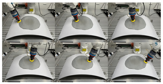
Figure 23.
Parallel grinding process.
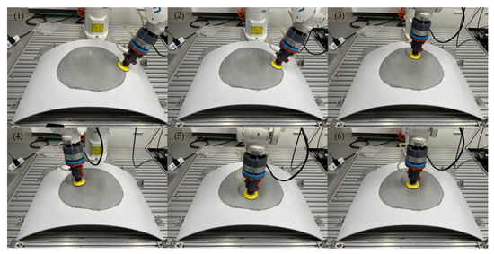
Figure 24.
Spiral grinding process.
Using the spiral grinding method, we ground the aluminum alloy surface and recorded the roughness measurements of the same points before and after grinding. The 16 points are illustrated in Figure 25.
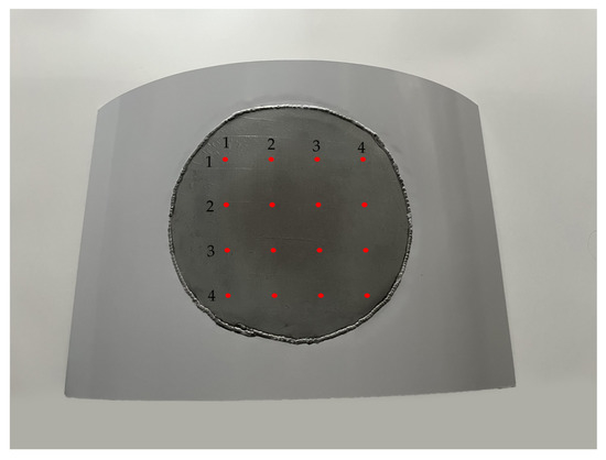
Figure 25.
Points for measuring roughness.
Figure 26 and Figure 27 display the process for measuring the roughness of each point before and after grinding, respectively.
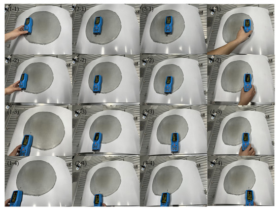
Figure 26.
Roughness measurement before grinding.
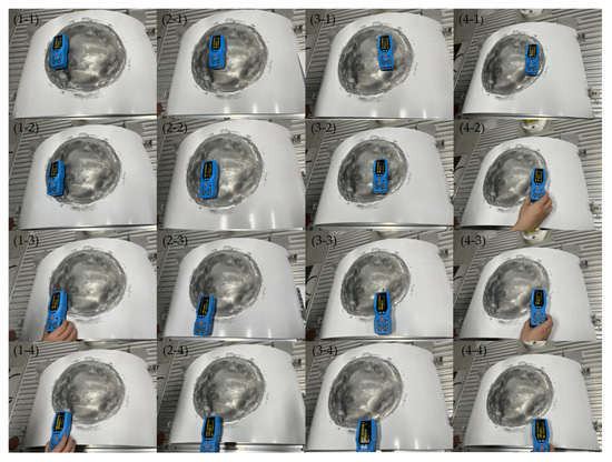
Figure 27.
Roughness measurement after grinding.
The roughness data for each point before and after grinding are shown in Figure 28. We measured 16 groups of roughness data on the surface of the workpiece after grinding, where 15 groups of roughness were below 0.8 microns and one group was 0.87 microns, meeting the requirements of aerospace grinding technology. Prior to grinding, the roughness of each point was larger with a wider range of variation, and the average value was 2.943. After grinding, the roughness of each point was significantly reduced, and the differences between the roughness values for each point were small, with an average value of 0.57. The average roughness value decreased by 80.63%, indicating the effectiveness of the spiral grinding method for grinding large aluminum alloy surfaces.
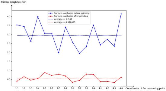
Figure 28.
Roughness comparison of each point before and after grinding.
7. Conclusions
This paper presents a method for automatic grinding of aluminum alloy surfaces based on recognizing and positioning welding seams. The method aims to reduce grinding time and improve grinding efficiency. To meet real-time grinding requirements in industrial environments and locate various defect areas on aluminum alloy surfaces in real-time, a high-speed and high-precision defect location method is proposed based on a combination of 2D images and 3D point clouds, which is a simplified theoretical model innovation. This method avoids the need for extensive calculations in weld seam and defect location, as the current location of the weld is based directly on 3D point cloud processing. Additionally, a weld reinforcement extraction method based on the orthogonal projection method is introduced to obtain characteristic information of weld reinforcement. A two-dimensional welding seam positioning method based on an improved Canny method is also proposed. The spatial position of the 3D weld and weld reinforcement is calculated by combining the relationship between two-dimensional and three-dimensional images and using orthogonal projection from the point to the surface. Most current grinding methods for curved surfaces are based on the parallel grinding trajectory using the slicing method. However, this method requires frequent advance and retreat of the grinding tools, resulting in low grinding efficiency. Therefore, a spatial spiral grinding trajectory planning method for complex surfaces with defects is proposed. Simulation and experimental results indicate that the spatial spiral method has much shorter grinding time and higher grinding efficiency than other methods. Moreover, the surface roughness after grinding is much smaller than before grinding, which proves the correctness and effectiveness of the spiral grinding trajectory planning and grinding method.
The method proposed in this paper is not only an efficient trajectory planning method for welding seams and defect areas, but also an efficient trajectory planning method for robot spraying. Compared with grinding, spraying does not require consideration of contact with the workpiece, and the other processes are similar to grinding, so the method proposed in this paper is also suitable for robot spraying operations. Since the main purpose of this paper is to demonstrate the effectiveness of visual measurement guidance and trajectory generation, this paper does not extensively study the factors that affect the quality of grinding, such as the end effector speed of the robot, the rotational speed of the grinding tool, the grinding force of the robot, and the selection of sandpaper. In the future, we will conduct further research on these aspects, and our team is currently conducting relevant research to determine the optimal parameter combination for grinding aerospace equipment under current grinding conditions.
Author Contributions
Conceptualization, H.Z., K.W. and Y.P.; methodology, H.Z. and K.W.; software, H.Z., T.L. and Y.X.; validation, H.Z., T.L. and Y.X.; formal analysis, H.Z. and K.W.; investigation, H.Z.; resources, K.W. and Y.P.; data curation, H.Z., T.L. and Y.X.; writing—original draft preparation, H.Z.; writing—review and editing, K.W. and Y.P.; visualization, H.Z.; supervision, K.W. and Y.P.; project administration, Y.P. All authors have read and agreed to the published version of the manuscript.
Funding
This research was funded by the Beijing Municipal Natural Science Foundation, grant number 3232018, by the National Natural Science Foundation of China, grant number 62003346, 52075533, and by the National Defense Basic Scientific Research program of China, grant number 2021203B035.
Institutional Review Board Statement
Not applicable.
Data Availability Statement
Data are contained within the article.
Acknowledgments
This work was supported in part by the Science, Technology and Innovation Commission of Shenzhen Municipality under grant no. ZDSYS20200811143601004.
Conflicts of Interest
The authors declare no conflict of interest.
References
- Ge, J.; Deng, Z.; Li, Z.; Li, W.; Lv, L.; Liu, T. Robot welding seam online grinding system based on laser vision guidance. Int. J. Adv. Manuf. Technol. 2021, 116, 1737–1749. [Google Scholar] [CrossRef]
- Ge, J.; Deng, Z.; Li, Z.; Li, W.; Liu, T.; Zhang, H.; Nie, J. An efficient system based on model segmentation for weld seam grinding robot. Int. J. Adv. Manuf. Technol. 2022, 121, 7627–7641. [Google Scholar] [CrossRef]
- Zhao, X.; Lu, H.; Yu, W.; Tao, B.; Ding, H. Vision-based Mobile Robotic Grinding for Large-scale Workpiece and Its Accuracy Analysis. IEEE/ASME Trans. Mechatron. 2022. [Google Scholar] [CrossRef]
- Zhang, H.; Li, L.; Zhao, J.; Zhao, J. The hybrid force/position anti-disturbance control strategy for robot abrasive belt grinding of aviation blade base on fuzzy PID control. Int. J. Adv. Manuf. Technol. 2021, 114, 3645–3656. [Google Scholar] [CrossRef]
- Yang, Y.; Ruoqi, W.; Yingpeng, W.; Yuwen, S. Contact force controlled robotic polishing for complex PMMA parts with an active end-effector. J. Adv. Manuf. Sci. Technol. 2021, 1, 2021012. [Google Scholar]
- Xu, P.; Cheung, C.F.; Wang, C.; Zhao, C. Novel hybrid robot and its processes for precision polishing of freeform surfaces. Precis. Eng. 2020, 64, 53–62. [Google Scholar] [CrossRef]
- Wang, X.; Zhang, X.; Ren, X.; Li, L.; Feng, H.; He, Y.; Chen, H.; Chen, X. Point cloud 3D parent surface reconstruction and weld seam feature extraction for robotic grinding path planning. Int. J. Adv. Manuf. Technol. 2020, 107, 827–841. [Google Scholar] [CrossRef]
- Wan, G.; Wang, G.; Fan, Y. A Robotic grinding station based on an industrial manipulator and vision system. PLoS ONE 2021, 16, e0248993. [Google Scholar] [CrossRef]
- Ding, Y.; Min, X.; Fu, W.; Liang, Z. Research and application on force control of industrial robot polishing concave curved surfaces. Proc. Inst. Mech. Eng. Part J. Eng. Manuf. 2019, 233, 1674–1686. [Google Scholar] [CrossRef]
- Zhang, T.; Su, J. Collision-free planning algorithm of motion path for the robot belt grinding system. Int. J. Adv. Robot. Syst. 2018, 15, 1729881418793778. [Google Scholar] [CrossRef]
- Qiu, L.; Qi, L.; Liu, L.; Zhang, Z.; Xu, J. The blade surface performance and its robotic machining. Int. J. Adv. Robot. Syst. 2020, 17, 1729881420914090. [Google Scholar] [CrossRef]
- Xie, X.; Sun, L. Force control based robotic grinding system and application. In Proceedings of the 2016 12th World Congress on Intelligent Control and Automation (WCICA), Paris, France, 26 July–1 August 2016; pp. 2552–2555. [Google Scholar]
- Zhou, H.; Ma, S.; Wang, G.; Deng, Y.; Liu, Z. A hybrid control strategy for grinding and polishing robot based on adaptive impedance control. Adv. Mech. Eng. 2021, 13, 16878140211004034. [Google Scholar] [CrossRef]
- Liu, H.; Wan, Y.; Zeng, Z.; Xu, L.; Zhao, H.; Fang, K. Freeform surface grinding and polishing by CCOS based on industrial robot. In Proceedings of the 8th International Symposium on Advanced Optical Manufacturing and Testing Technologies, Advanced Optical Manufacturing Technologies, Suzhou, China, 26–29 April 2016; Volume 9683, pp. 587–593. [Google Scholar]
- Tian, F.; Lv, C.; Li, Z.; Liu, G. Modeling and control of robotic automatic polishing for curved surfaces. CIRP J. Manuf. Sci. Technol. 2016, 14, 55–64. [Google Scholar] [CrossRef]
- Tian, F.; Li, Z.; Lv, C.; Liu, G. Polishing pressure investigations of robot automatic polishing on curved surfaces. Int. J. Adv. Manuf. Technol. 2016, 87, 639–646. [Google Scholar] [CrossRef]
- Lin, H.I.; Dubey, V. Design of an adaptive force controlled robotic polishing system using adaptive fuzzy-PID. In Proceedings of the Intelligent Autonomous Systems 15, the 15th International Conference IAS-15, Baden, Germany, 11–15 June 2019; pp. 825–836. [Google Scholar]
- Kharidege, A.; Ting, D.T.; Yajun, Z. A practical approach for automated polishing system of free-form surface path generation based on industrial arm robot. Int. J. Adv. Manuf. Technol. 2017, 93, 3921–3934. [Google Scholar] [CrossRef]
- Mineo, C.; Pierce, S.G.; Nicholson, P.I.; Cooper, I. Robotic path planning for non-destructive testing–A custom MATLAB toolbox approach. Robot. Comput. Integr. Manuf. 2016, 37, 1–12. [Google Scholar] [CrossRef]
- Wei, W.; Chao, Y. A path planning method for robotic belt surface grinding. Chin. J. Aeronaut. 2011, 24, 520–526. [Google Scholar]
- Ma, K.; Han, L.; Sun, X.; Liang, C.; Zhang, S.; Shi, Y.; Wang, X. A path planning method of robotic belt grinding for workpieces with complex surfaces. IEEE/ASME Trans. Mechatron. 2020, 25, 728–738. [Google Scholar] [CrossRef]
- Morozov, M.; Pierce, S.; MacLeod, C.N.; Mineo, C.; Summan, R. Off-line scan path planning for robotic NDT. Measurement 2018, 122, 284–290. [Google Scholar] [CrossRef]
- Ren, X.; Chen, G.; Wang, Z.; Wang, Z.; Sun, L. Polishing path planning based on point cloud. In Proceedings of the 2020 the 4th International Conference on Innovation in Artificial Intelligence, Xiamen, China, 6–9 March 2020; pp. 222–228. [Google Scholar]
- Zhang, G.; Wang, J.; Cao, F.; Li, Y.; Chen, X. 3D curvature grinding path planning based on point cloud data. In Proceedings of the 2016 12th IEEE/ASME International Conference on Mechatronic and Embedded Systems and Applications (MESA), Auckland, New Zealand, 29–31 August 2016; pp. 1–6. [Google Scholar]
- Chen, W.; Li, X.; Ge, H.; Wang, L.; Zhang, Y. Trajectory planning for spray painting robot based on point cloud slicing technique. Electronics 2020, 9, 908. [Google Scholar] [CrossRef]
- Zhang, Z.; Zhang, H.; Yu, X.; Deng, Y.; Chen, Z. Robotic Trajectory Planning for Non-Destructive Testing Based on Surface 3D Point Cloud Data. J. Phys. Conf. Ser. IOP 2021, 1965, 012148. [Google Scholar] [CrossRef]
- Yang, L.; Liu, Y.; Peng, J.; Liang, Z. A novel system for off-line 3D seam extraction and path planning based on point cloud segmentation for arc welding robot. Robot. Comput. Integr. Manuf. 2020, 64, 101929. [Google Scholar] [CrossRef]
- Geng, Y.; Zhang, Y.; Tian, X.; Shi, X.; Wang, X.; Cui, Y. A method of welding path planning of steel mesh based on point cloud for welding robot. Int. J. Adv. Manuf. Technol. 2021, 116, 2943–2957. [Google Scholar] [CrossRef]
- Yu, X.; Cheng, Z.; Zhang, Y.; Ou, L. Point cloud modeling and slicing algorithm for trajectory planning of spray painting robot. Robotica 2021, 39, 2246–2267. [Google Scholar] [CrossRef]
- Gleeson, D.; Jakobsson, S.; Salman, R.; Ekstedt, F.; Sandgren, N.; Edelvik, F.; Carlson, J.S.; Lennartson, B. Generating optimized trajectories for robotic spray painting. IEEE Trans. Autom. Sci. Eng. 2022, 19, 1380–1391. [Google Scholar] [CrossRef]
- Trigatti, G.; Boscariol, P.; Scalera, L.; Pillan, D.; Gasparetto, A. A look-ahead trajectory planning algorithm for spray painting robots with non-spherical wrists. In Proceedings of the 4th IFToMM Symposium on Mechanism Design for Robotics, Udine, Italy, 11–13 September 2019; pp. 235–242. [Google Scholar]
- Zhang, B.; Wu, J.; Wang, L.; Yu, Z. Accurate dynamic modeling and control parameters design of an industrial hybrid spray-painting robot. Robot. Comput. Integr. Manuf. 2020, 63, 101923. [Google Scholar] [CrossRef]
- Xu, J.; Xu, L.; Sun, Y.; Lee, Y.S.; Zhao, J. A method of generating spiral tool path for direct three-axis computer numerical control machining of measured cloud of point. J. Comput. Inf. Sci. Eng. 2019, 19, 041015. [Google Scholar] [CrossRef]
- Pan, Y. ARIS. [EB/OL]. Available online: http://www.github.com/py0330/aris (accessed on 5 January 2023).
Disclaimer/Publisher’s Note: The statements, opinions and data contained in all publications are solely those of the individual author(s) and contributor(s) and not of MDPI and/or the editor(s). MDPI and/or the editor(s) disclaim responsibility for any injury to people or property resulting from any ideas, methods, instructions or products referred to in the content. |
© 2023 by the authors. Licensee MDPI, Basel, Switzerland. This article is an open access article distributed under the terms and conditions of the Creative Commons Attribution (CC BY) license (https://creativecommons.org/licenses/by/4.0/).