Article

On a Vision-Based Manipulator Simulator

School of Engineering and Architecture, University College Cork, College Road, T12K8AF Cork, Ireland
*
Author to whom correspondence should be addressed.
Actuators 2023, 12(2), 78; https://doi.org/10.3390/act12020078
Submission received: 11 January 2023 / Revised: 4 February 2023 / Accepted: 9 February 2023 / Published: 12 February 2023
(This article belongs to the Section Control Systems)

Abstract

:
This paper presents a typical grasp–hold–release micromanipulation simulator based on MATLAB and Simulink. Closed-loop force and position control were implemented only based on a camera. The work was mainly focused on control performance improvements and GUI design. Different types of control strategies were investigated in both the position and force control processes. Finally, incremental PID and positional PID were adopted in the gripper position control and force control processes, respectively. The best performance of the gripper position control was the fast response of 0.3 s without overshoot and steady-state errors in the range of 10–40 Hz. The new camera control algorithm kept a big motion range (4.48 × 4.48 mm) and a high position resolution of 0.56 µm, with a high force resolution of 1.56 µN in the force control stage. The maximum error between the measured force and the real force was maintained below 4 µN. The steady-state error and the setting time were less than 1.2% and less than 1.5 s, respectively. A separate app, the Image Generation Simulator app, was developed to assist users in getting suitable initial coordinates, camera parameters, desired position resolutions, and force resolutions, which are packed as a standalone executable file. The main app can run the simulation model, debug, playback, and report simulation results, and calculate the calibration equation. Different initial coordinates, camera parameters, sample frequencies, controller parameters, and even controller types can be adjusted from this app.

1. Introduction

With the development of computer science, mechanics, electronics, and materials, miniaturized robots have become more of a possibility. In recent decades, micromanipulation has attracted more and more attention due to increasing demand from industrial and scientific research areas such as micro-assembly and biological engineering [1,2]. Micromanipulation technology can be applied to micro-electromechanical systems (MEMSs), atomic force microscopy, scanning probe microscopy, and wafer alignments et al. [3,4,5,6].
Position control and force control are necessary for many of these applications because the manipulated objects, such as living cells and microwires, are often very fragile. Accurate position and force control have to rely on closed-loop feedback control. However, operations on a microscale are not as easy as those on a macroscale. Sensors with high precision and small size are either extremely expensive or do not exist. Biocompatibility may even need to be considered in some environments. Fortunately, the development of computer science and image processing technology has enabled micro-vision to replace traditional position and force sensors. Compared with traditional sensors, micro-vision has the advantages of developability, flexibility, multi-DOF measurement, lower cost, noncontact, and ease of installation [7,8]. Other sensors, such as laser measurement sensors, have very strict installation requirements, and even the mechanism needs to be redesigned. Unlike capacitive sensors or piezoelectric sensors, the micro-vision system can be used for measurements in multi-DOF, even in different parts. The micro-vision system only obtains images either from the camera directly or from the camera mounted on microscopy. The authors of [9] have demonstrated the capability of the micro-vision system in displacement measurements based on a CCD camera and microscopy, which achieved an accuracy of 0.283 µm. Another study [10] presented a 3-DOF micro/nano positioning system, which employs a micro-vision system for real-time position feedback. With the assistance of microscopy, the image resolution can be at 56.4 nm at a 30 Hz sampling frequency.
In addition to position measurement, micro-vision also presents a good ability in force measurement. Different types of vision-based force measurement methods have been proposed, including investigating the relationship between force and displacement, building the analytical mathematic model for force and deformation, and slip margin analysis et al. [11,12,13]. The general idea of retrieving the force is based on the deformation measured from the images. Two common methods for deformation measurement are template matching and edge detection. The authors of [14] used two CCD cameras to accomplish accurate position feedback and simple force feedback in a microgripper system. An external camera was used to perform a course positioning. Combined with microscopy, the other camera worked to obtain precise position measurements. Template matching was used for a simple force estimation [15] and to propose a vision-based force measurement, which switched the measurement of force distribution to a linearly elastic object’s contour deformation. The deformable template matching method was used to retrieve the force, and a +/−3 mN microgripper force resolution was achieved. Another study [2] utilized finite-element analysis to determine the relationship between microgripper deformation and force. As a result, the displacement and force were subjected to a linear relationship, which reduced the problem of displacement measurement. The authors of [13] demonstrated a microgripper consisting of a force-sensing arm designed by a compliant right R joint. The moment and deformation angle were fitted as a first-degree equation. The deformation of the microgripper was obtained by Sobel edge detection. In [16], a 3D finite-element model was used to obtain the relationship between the force and deformation of the microgripper. A nonlinear relation was fitted as a second-order degree equation. Pattern identification was performed to obtain the relative displacement of the microgripper. The authors of [17] proposed a vision-based force measurement method based on an artificial neural network. The biological cells’ geometric features from images and measured force were used to train the model. Based on zebrafish embryos, a cellular force analysis model was created in [18]. The injection force was obtained according to the measured cell post-deformation. With the assistance of a microscope and camera, the vision-based force-sensing system achieved a 3.7 µN N resolution at 30 Hz.
Force and position control are other vital problems in the micromanipulation process. Different types of control strategies and methods have been exhibited to meet the challenge of the smooth transition between position and force control. A position and force switching control was adopted in [19]. An incremental PID and a discrete sliding mode control (SMC) were utilized in the position and force control stages, respectively. An indicator of position and force control was the contact between the microgripper and the object; meanwhile, the sensed force exceeded a certain threshold. Similarly, an incremental-based force and position control strategy was proposed in [20]. An incremental PID and an incremental discrete sliding mode control were used in the position and force control process, and the state observer is no longer necessary. Rather than using two types of controllers, the authors of [21] adopted a single control to accomplish position and force control based on the impedance control, which enabled it to work in high-order and high-speed systems. Some advanced control strategies, such as fuzzy control, hybrid control, and neural network control [22,23,24,25], have also been presented, although some of them are either difficult to implement or computationally expensive.
Although many hardware systems have been presented, few simulation systems exist. Rather than working on a hardware setup, this system was implemented with software simulation. Compared with hardware systems, software simulation has some advantages; for example, it is easier to obtain the control performance in each process, it is more convenient to investigate the effect of different parameters on the performance, and it is easier to test different control strategies and vision-based force measurement methods. Compared with real experiments, simulations can perform experiments with different structural grippers and objects at a lower time and money cost. A successful simulation can provide a valuable reference for the real experiment design. This simulation system is a continuation of the first generation based on MATLAB and Simulink. This generation mainly focused on improvements in control performance and GUI design. The closed-loop position and force control are implemented based on a virtual camera. Different types of control strategies are investigated in each stage. The GUI was designed using MATLAB App Designer.
In this paper, Section 2 presents the components of the mechanical system. Section 3 is the key part, which demonstrates the design of the control system and the vision-based force measurement and control. Section 4 is the GUI design. Section 5 discusses some assumptions. Finally, Section 6 gives the conclusion and future work.

2. Mechanical System

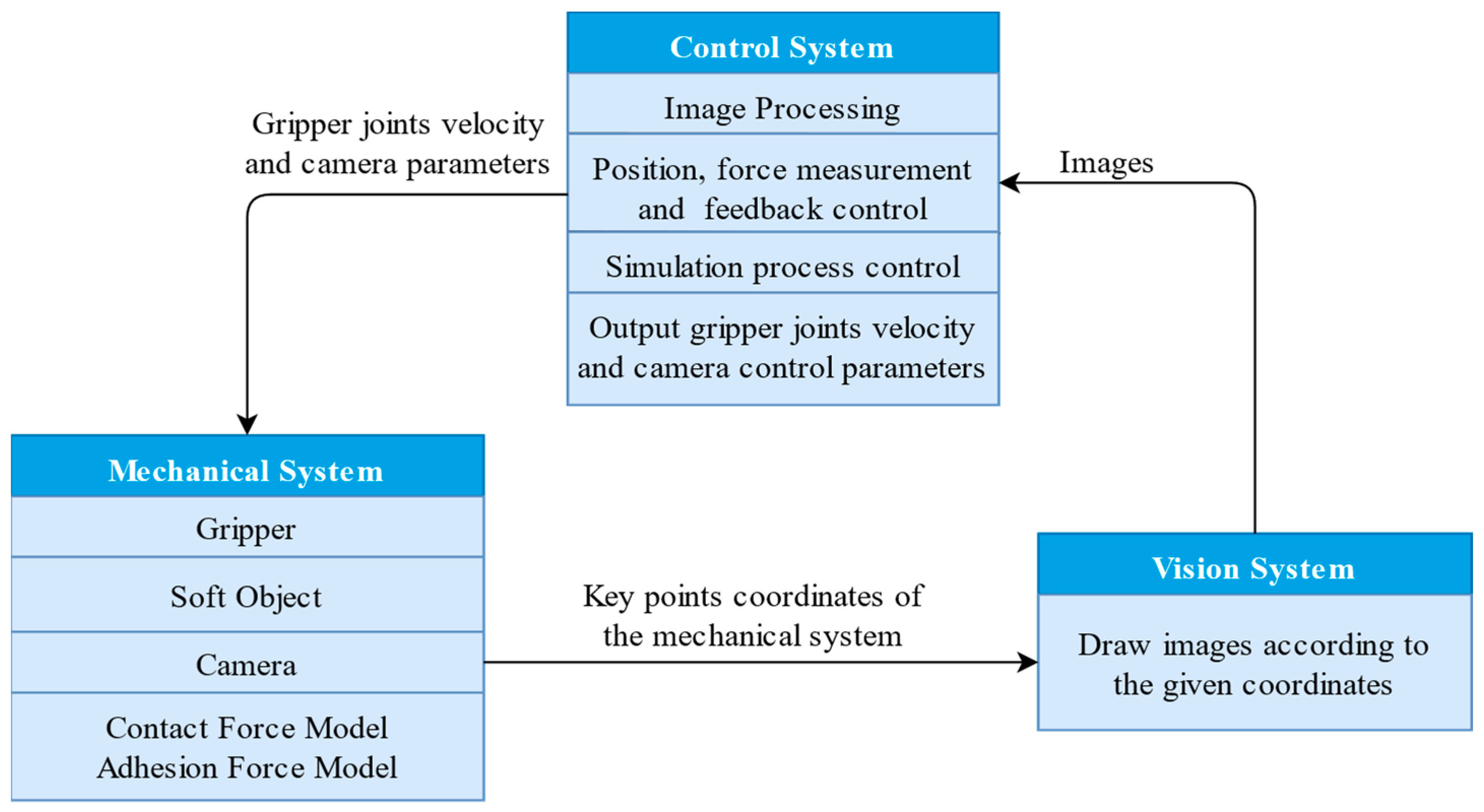
The simulation system can be divided into three parts: the mechanical system, the vision system, and the control system. The relationship between these three parts can be seen in Figure 1. The mechanical system is the 3D gripper model created by the Simulink Simcape Library. The vision system generates images according to the coordinates of the key points from the mechanical system during the simulation process, which provides a feedback role. The control system outputs the gripper joints’ velocity after an analysis of images from the vision system.
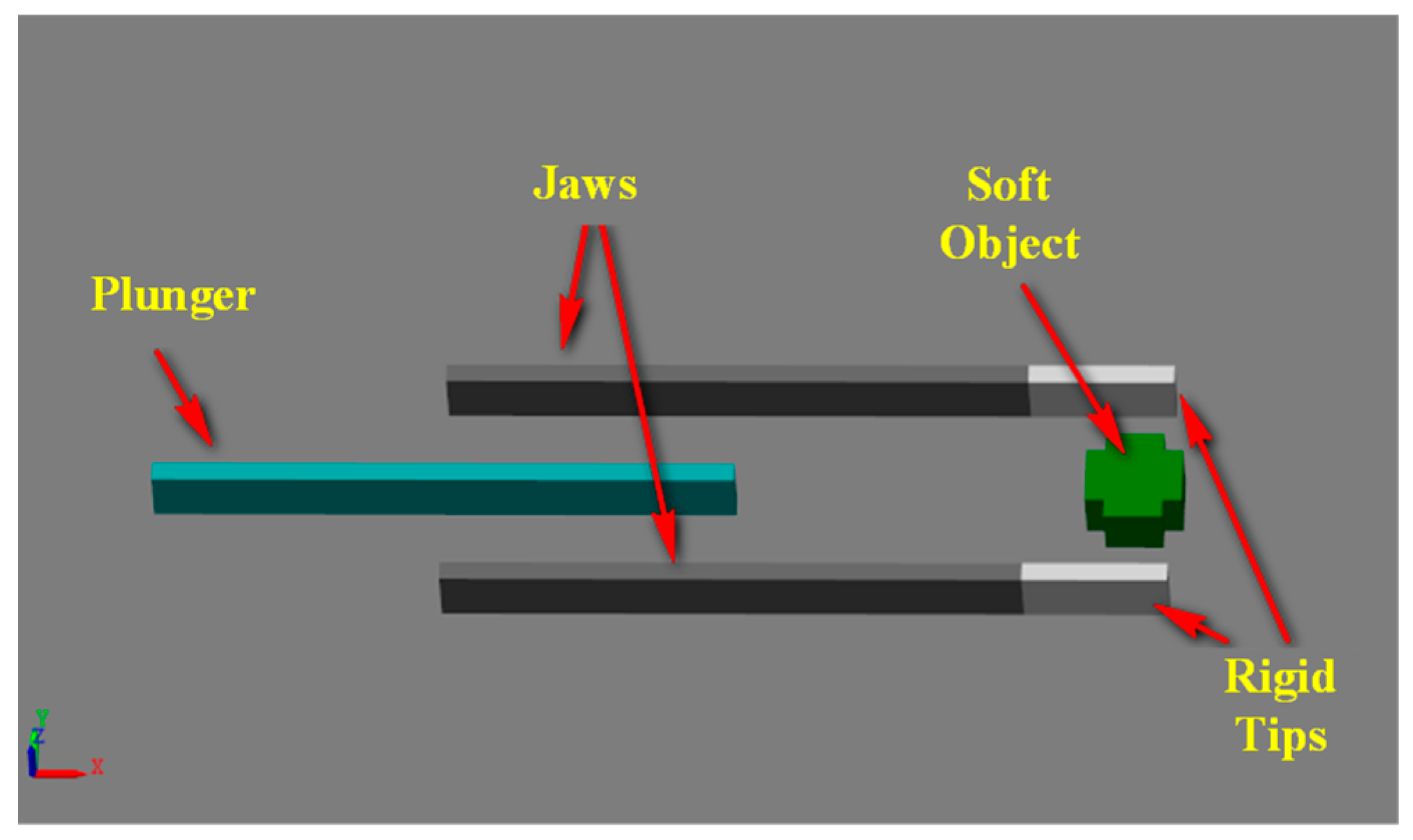
The mechanical system includes the gripper, soft object, camera model, and force model. Figure 2 shows the 3D gripper model, which is comprised of two jaws, two rigid tips, and a plunger. Both jaws can be opened or closed in parallel. The plunger is used to remove the soft object from the tip because the soft object would be stuck on the tip due to the adhesion force on the microscale. The gripper has three translational degrees of freedom (DOFs) in this 3D space and a rotational DOF in the horizontal plane.
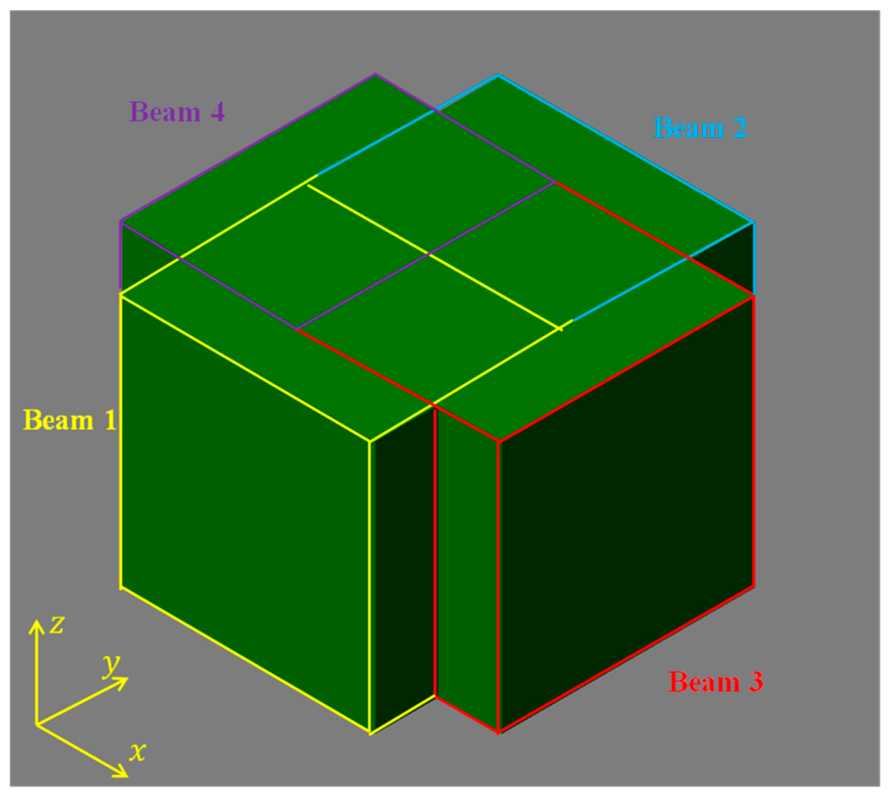
Because of the limitations of Simulink, a completely flexible ball cannot be modeled. A soft object model was employed as an alternative. The size of the soft object was about 500 μm. Figure 3 illustrates the soft object model, which is composed of four flexible beam elements with some overlap in the center area. Each beam element includes two rigid bodies connected by a prismatic joint. The soft object can be squeezed in the x- or y-direction, which is used to simulate the deformation of a ball in the diameter direction. The soft object model took the idea of the lumped-parameter method and the finite-element method [26].
To simulate a collision effect between the gripper and the soft object, the contact force model was employed from the Simscape Multibody Contact Force Library. In the microscale, the adhesion force is not negligible. In contrast, the dominative forces in the macroscale, such as gravity, are not that important. A simplified Van der Waals force model was created to simulate the adhesion phenomenon between the gripper and the soft object [27].
The camera is located at the right top of the plane, which has three translational degrees of freedom. The virtual camera is a center camera from Peter Corke’s Machine Vision Toolbox, which generates images with the central project method [28]. The coordinates transformation from camera frame to image frame can be seen in Equation (1):
u = f p z X Z + u 0 v = f p z Y Z + v 0
where u , v are the target point coordinates with regard to the image frame; u 0 , v 0 are the principal point coordinates in the image view; X , Y , Z are the target point coordinates with regard to the camera frame; f and p z are the focal length and pixel size of the virtual camera.

3. Control System

3.1. Overview

The control system, as one of the most important parts, takes charge of the whole process of regulation, image processing, and control strategies implementation. A new control system was developed, and the structure can be seen in Figure 4. The whole process can be divided into six steps: gripper position control, camera control, jaw position control, force control, hold and release.
The simulation process in image view can be seen in Figure 5. The gripper position control aims to align the gripper tips’ center and the object center and prepare for the grasping process. The camera control regulates the image view and zooms in on an interesting area so that a higher position and force resolution can be acquired. This is followed by jaw position control, which closes both jaws to make contact. After contact, the position control switches to the force control. When the measured force arrives at the reference force, the force control ends. In the holding stage, the gripper does nothing but wait for several seconds. Finally, both jaws open and move the plunger to remove the object.

3.2. Gripper Position Control

Before the grasping process, the gripper tips should surround the object, and no collision happens in this process. A closed-loop position control was implemented based on the virtual camera. The control structure can be seen in Figure 6. Images from the camera are filtered and enhanced, and then the coordinates of the object center and gripper tips’ center are extracted to feed the controller. Finally, the gripper velocities in the x- and y-directions are output to update the status of the mechanical model.
Different types of controllers were tested in this process: P, positional PID, improved positional PID, and incremental PID. Finally, the incremental PID was adopted because of its better performance. The position control in the x- and y-directions are noncoupled; thus, coordination in both directions has to be considered to avoid a collision during this process. Figure 7 shows the control performance of gripper position control with incremental PID at 30 Hz.
Table 1 demonstrates the performance of gripper position control with different sample frequencies as well as a comparison with that of the original generation. It can be seen that the adjustment time has been significantly reduced, and the steady-state error has been eliminated at the range of 10–40 Hz.

3.3. Camera Control

The camera control aims to regulate the field of image view and improve the position resolution and force resolution in the force control stage. In the gripper position control stage, a bigger field of image view enables the gripper to move in a wider range. However, the bigger the field of the image view, the lower the position resolution will be. After the gripper position control, the focal length and the camera’s z position control make the image view focus on an interesting area, which maintains a bigger motion range in the gripper position control stage as well as higher position resolution and force resolution in the force control stage.
According to the coordinate transformation from camera frame to image frame, Equation (1) can be rewritten as:
P = f p z L Z c + p p   ( 0 P R )
where L is the x or y coordinates of a target point with regard to the camera frame (unit: m); P is the x or y coordinates ( u or v ) of a target point about the image frame (unit: pixel), which should be in the range of the image resolution (R); p p is the principal point coordinates ( u 0 or v 0 ); Z c is the z coordinate of a target point with regard to the camera frame (unit: m).
From Equation (2), the position resolution can be represented as:
d L d P = p z f Z c = Z c G x
G x = f p z
From Equation (3), the f should be as big as possible and the p z and Z c should be as small as possible in order to improve the position resolution. Therefore, the camera’s z position and focal length were adjusted in the camera control process. Table 2 shows the camera’s intrinsic parameter changes before and after the camera control.
From Table 2, the gripper motion range in the gripper position control stage was 4.48 × 4.48 mm. In the original generation, the gripper motion range was only 1.8 × 1.8 mm. The theoretical position resolution has also been improved to 1.12 µm.

3.4. Jaw Position Control

In this stage, both jaws close to make contact between the tips and the soft object. A new P controller is employed. The feedback variable is the gap between the jaws and the object, which has been transferred into the real distance with units of meters to avoid the effect of different camera parameters in the last stage. Figure 8 and Equation (5) illustrate the calculation of the gap between the jaws and the object.
G 1 = G 2 L o 2
where G 1 is the gap between the jaw and the object; G 2 is the gap between both jaws; L o is the object length.
It can be seen that the object length has to be known in advance; thus, the object length measurement is executed with a new image processing algorithm. The new image processing includes image cropping, filtering, binarization, and feature extraction, which solves the problem in the original generation where the measured results did not always have the same value, even within the same scene. Figure 9 shows the 40-times continuous measurement results before and after the image processing in the same scene; we can see that the new measurement algorithm has presented a more stable performance.
A comparison of jaw position control between the original generation and the new generation can be seen in Table 3. It can be seen that the adjustment time has been overwhelmingly reduced from 1.7 to 0.4 s, which is attributed to the fewer control states and shorter measurement time. In the jaw position control process of the original generation, two control states were included, fast close and slow close, whereas only one state with a new P controller completed this process in the new generation. With the new image processing algorithm, the times of object length measurement were reduced from 20 to 1, but with more accurate results. Compared with the 26 µN max contact force in the original generation, the contact force has been decreased to 0 due to a new end condition and contact detection algorithm.

3.5. Force Control

After both jaws close, the force control is executed. The contact status is used as an indicator that the position control has been transferred to the force control. At the end of the position control, the velocities of both jaws decrease to 0. In the force control stage, the jaw’s velocity would increase from 0, which ensures a smooth transition between position and force control.
Vision-based force measurement is based on the linear relationship between force and displacement. Therefore, two important things to retrieve force are the calibration equation and soft object deformation. The calibration equation can be obtained by squeezing the soft object and fitting the force and soft object displacement data. The data from Simscape is considered as the true value. Experiments have been designed to investigate whether the jaws’ velocity and camera parameters affect the calibration equation. It has been confirmed that they almost do not affect it. Figure 10 shows the calibration result; we can see that the relationship between contact force and object length has been perfectly fitted as a first-degree equation.
According to the calibration results, the relationship between contact force and soft object displacement is:
F   =   2.7778 L   +   0.0013889
Combined with Equation (3), the force resolution can be represented as:
d F d P = d F d L d L d P = p Z c G x
k = d F d L = 2.7778
After contact, the edges of the soft object cannot be identified. The gap between both jaws is used to represent the soft object length. Two main methods were tested for the soft object length measurement: the find peaks method and the center point method. The find peak method locates the edges’ coordinates of the jaws and the object by the “findpeak” function to obtain the gap between both jaws. The principle of the center point method can be seen in Figure 11.
After image cropping, filtering, and enhancement, the center coordinates of both jaws are extracted, and the length of the jaw tips is measured before the force control. The gap between both jaws can be acquired by the coordinate of the tips’ edges. Compared with the find peak method, the position resolution and the force resolution have doubled in the center points method.
The closed-loop force control structure can be seen in Figure 12. The vision-based force measurement (VBFM) provides the measured force. The controller outputs the jaw’s velocity to update the gripper status.
Different types of controllers were discussed in the processes of P, PI, position PID, and incremental PID. Finally, the positional PID control was adopted because of its better performance. Figure 13 shows the force control performance with positional PID at 30 Hz.
A performance comparison between the original generation and the new generation can be seen in Table 4. Sample frequency in the 10–40 Hz range was tested in this process. The position resolution and the force resolution improved by 75.33% and 45.07%, respectively. The maximum measured force error decreased from 15 to less than 4 μN. The setting time and percent of the steady-state error were also significantly reduced.

4. GUI Design

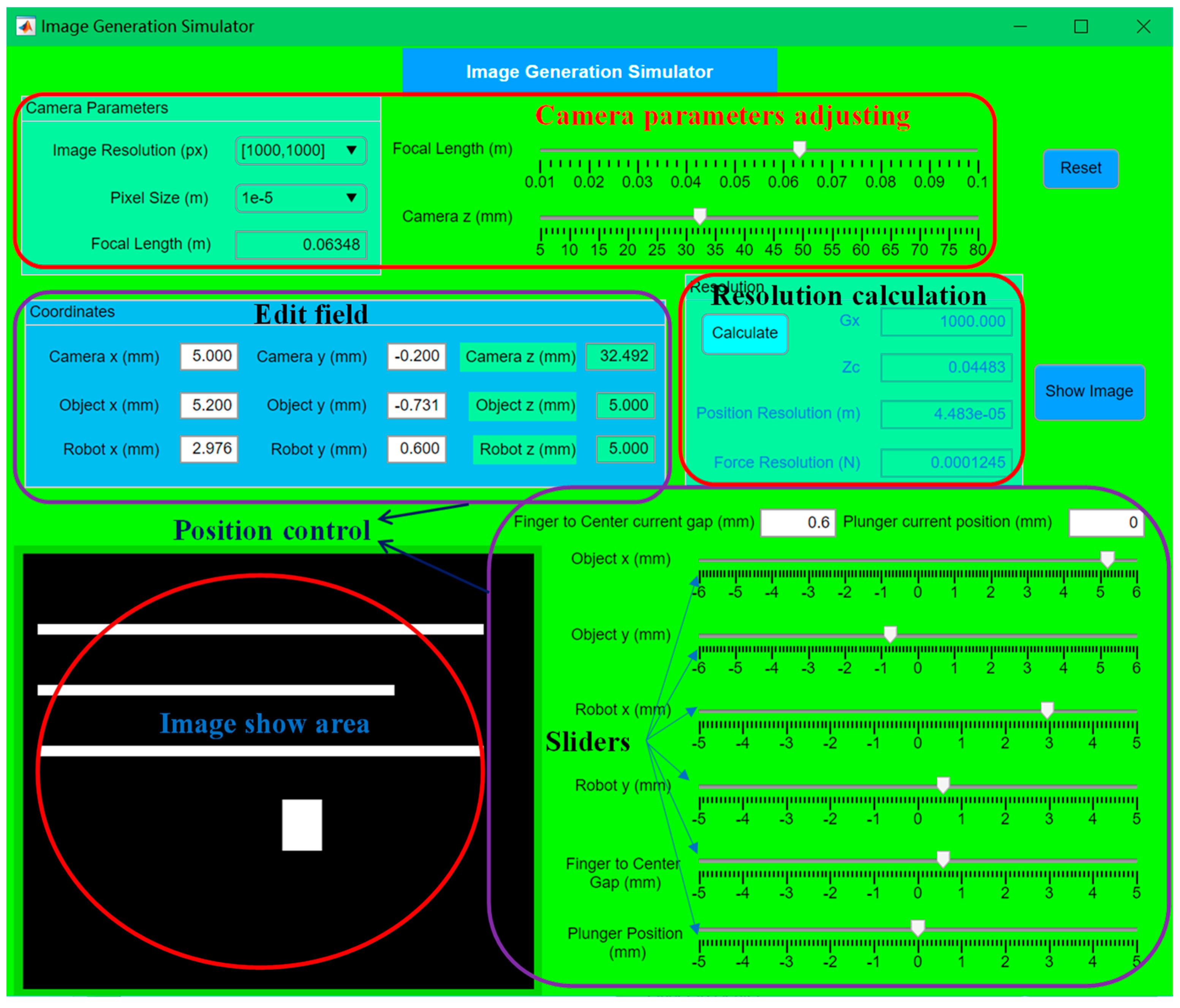
The GUI aims to help users run this system without changing the complicated code. This GUI was designed by MATLAB App Designer; it includes two parts: an image generation simulator and the main app. The Image Generation Simulator app assists users in getting suitable initial coordinates, camera parameters, as well as desired position resolutions and force resolutions. The main app is used to control the whole simulation process, including parameter settings, debugging, playback, calibration, and results reports.
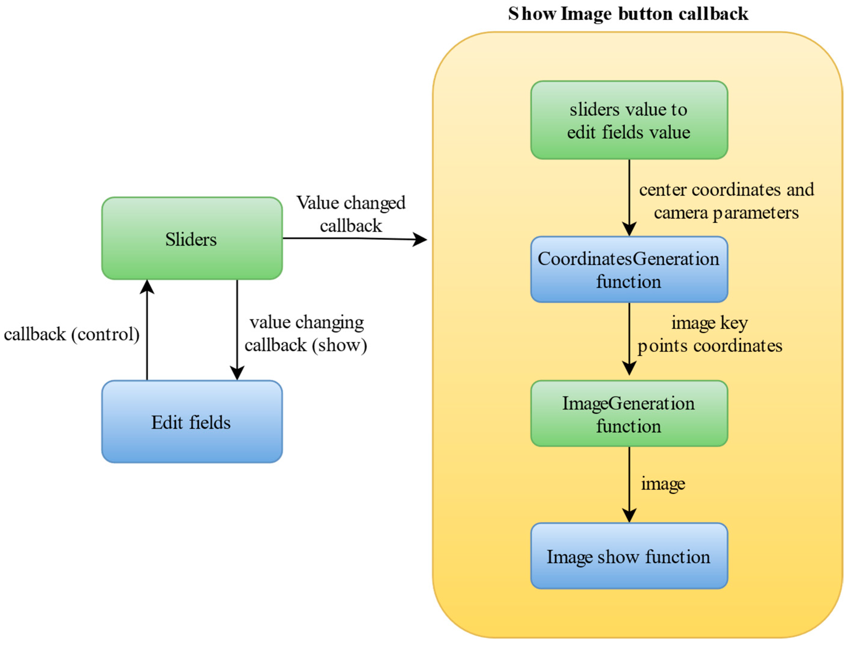
Figure 14 shows the interface of the Image Generation Simulator app, which includes two functions: image showing and resolution calculation. Position resolution and force resolution are calculated automatically if the camera parameters are changed. The image show area updates when the coordinates or camera parameters are changed. The programming structure can be seen in Figure 15; rather than each edit field and slider being attached to the same image show program, a show image button callback function is called by all the sliders and edit fields, which saves loads of coding.
From Figure 15, it can be seen that a complete image generation system is planted into this app, including the coordinates generation function and the image generation function. This image generation system is the same as that in the simulation process. The camera parameters and gripper coordinates affect the generated images. This app has been packed as a standalone executable, which can be run on a computer even if it does not have MATLAB. A presentation video can be found in Appendix A.
Figure 16 presents the steps of the main app. According to the function, it can be divided into three parts: software introduction, parameters setting, and model running. The first two steps are the software introduction. Steps 3, 4, and 5 are used to adjust the simulation parameters. The last four function tabs are model running, debugging, calibration, and playback.
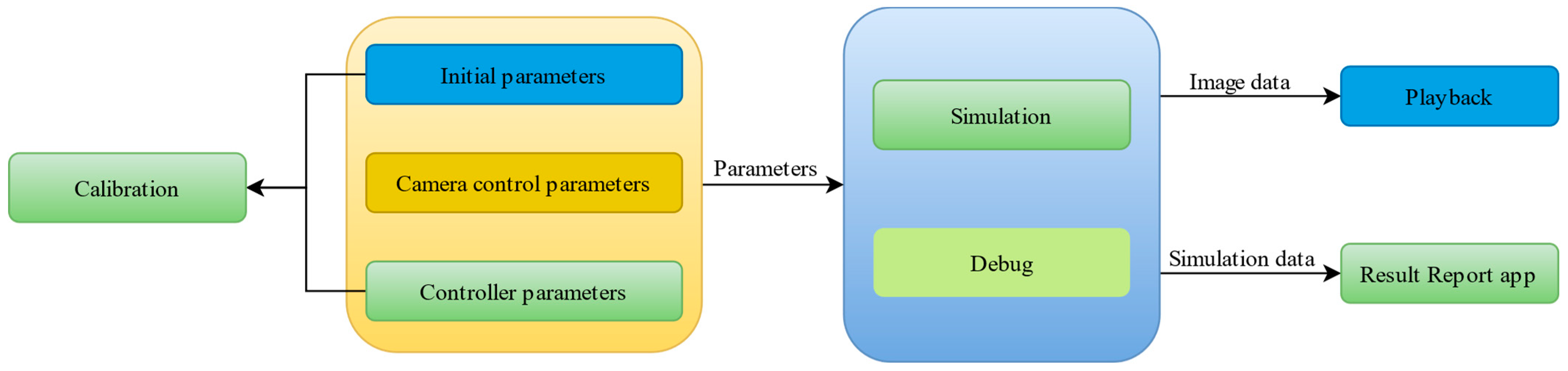
Figure 17 shows the relationship between each tab page. The initial parameters, camera control parameters, and controller parameters are set from the MATLAB App Designer workspace, passed to the base workspace, and, finally, received by the Simulink model.
The simulation and debug function sends a command to the Simulink model to start the model running. After the simulation, the image data and simulation results are saved for the playback and results report. Part of the initial parameters and controller parameters, such as initial coordinates, initial camera parameters, and gripper position control parameters, are also used for the calibration process.
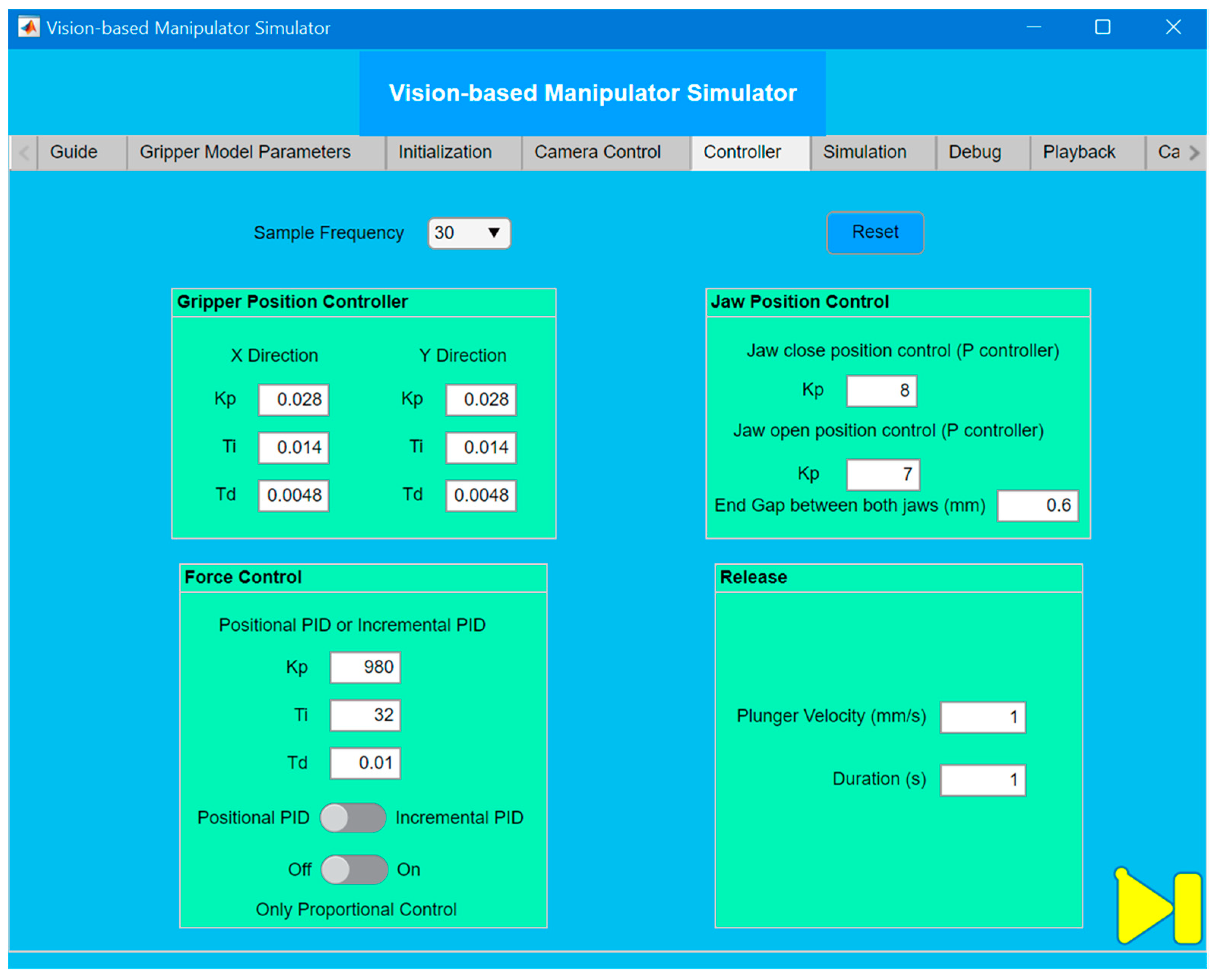
Figure 18 shows the interface of the controller tab page. The controller parameters and even the controller types can be changed for each control stage. Different sample frequencies can be chosen from the 10–40 Hz range. Groups of controller parameters with specific sample frequencies have been saved, which can be updated automatically when different sample frequencies are chosen. Any other controller parameters can also be set by users for the debugging stage.
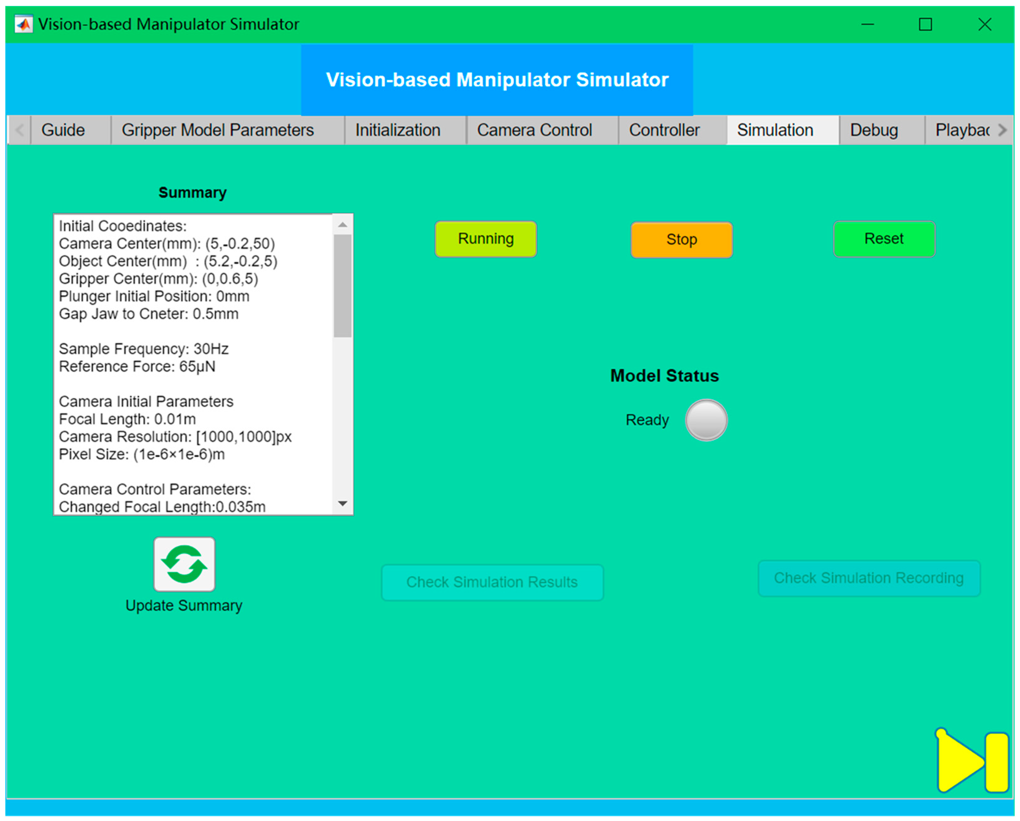
The simulation page can be seen in Figure 19. After all the initial parameters are set, the summary area will show the setting parameters. Clicking the run button, all the parameters are passed to the base workspace, and the Simulink model is called. The model status lamp and text area will show the current state of the Simulink model. Until the end of the model running, the Check Simulation Results and Check Simulation Recording buttons are available. These two buttons call back the results report app and playback tab page, respectively. A video of the simulation process can be seen in Appendix A.
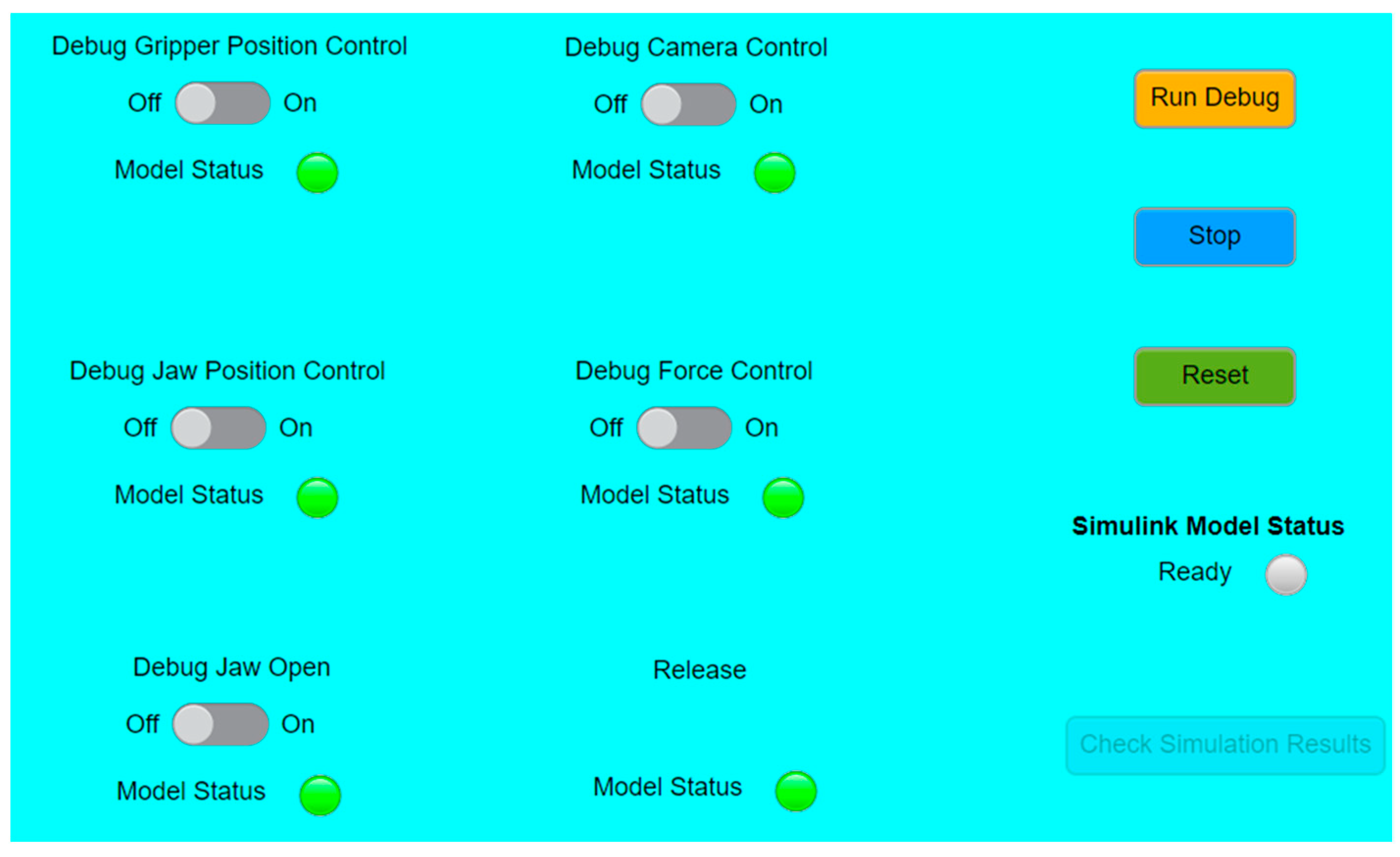
The interface of the debug panel can be seen in Figure 20. Each simulation stage has a switch and a lamp. If the switch is turned on, the process before this stage will run and the lamps will be on, while the process after this stage will not be run and the corresponding lamps will be off. Clicking the run debug button, the Simulink model will be run.
After either the simulation or debugging, the Check Simulation Results button will lead users to the result report app. The interface of the results report app can be seen in Figure 21. This app includes three-tab pages: the Gripper Position Control, Jaw Position Control, and Force Control pages. Each page can be used to present the control performance of the corresponding stage and the recording of relative variables. For each figure area, many available figures can be shown, which is very convenient for the debugging process. The pages of jaw position control and force control have a similar layout and function.
The playback function can be used to check the previous simulation recording after loading the generated image file. It included two functions: continuous play and single frame check. In the continuous play mode, the play speed can be adjusted. These two functions can not be run at the same time. The other function would be enabled until one of them comes to an end. In the single image frame check mode, just input the frame number and click the show button, and the specific image frame will be shown in the image area. The calibration function can also be executed on the last page. This process consists of two stages: gripper position control and jaws closing. After setting the jaws’ velocity and turning on the calibration switch, the Simulink model will be run. At the end of the simulation, the calibration results are shown in the figure area. A video of the debugging, playback and calibration processes can also be seen in Appendix A.

5. Discussion

In this paper, we have made some assumptions to simplify the experiments, which also prepares us for work on the next generation. Firstly, the soft object was assumed to be static and not move. In some environments, the target objects can not only randomly rotate and oscillate but also flow at speed, such as cells in blood vessels. Dynamic grasping would be more interesting and meaningful. To realize the same position/force control performance, the camera motion control and autofocus might be applied. Secondly, in different tasks, such as cell grasping, wafer aligning, and micro-assembling, the shape and material of the targets might be very different. A rotational degree of freedom for the gripper has been designed for an attitude adjustment in the future. In different environments, the force models might be adjusted differently. Lastly, in the holding phase, the object was just held for several seconds to replace a following complex operation, and the adhesion between the object and plunger was assumed to be zero. The releasing process needs to be carefully considered due to the dominative adhesion force on a microscale. Different releasing methods have been discussed in the previous paper to detach the objects from both jaws, such as electric fields, vacuum-based tools, plungers, and mechanical vibration. Compared with the adhesion force between the jaws and the soft object, the adhesion force between the plunger and the object is not significant due to the smaller contact area. The object can be easily removed by a simple vibration or retracing the plunger at high acceleration. However, in some tasks, target objects are required to be released at an accurate position and attitude. Additionally, fragile objects cannot be damaged. In the next generation, release technology will be explored in specific environments.

6. Conclusions and Future Work

This paper presents a work of vision-based micromanipulation simulation. Compared with the original generation, this new work has mainly focused on improvements in the control performance and GUI design. The new control system is faster, simpler, and more accurate. Different types of control strategies were implemented in each stage. In gripper position control, the incremental PID control was adopted, and different sample frequencies were tested. The shortest adjustment time was only 0.3 s, with an improvement of over 50%. The new camera control algorithm maintained a bigger gripper motion range and higher position resolution and force resolution at the same time. The gripper motion range was enlarged from 1.8 × 1.8 mm to 4.48 × 4.48 mm. The jaw position control was accomplished faster and with more stability without contact force happening. In the force control stage, the sampling frequency was enlarged from 10 to 10–40 Hz. The position resolution and force resolution were improved from 2.27 to 0.56 µm and 2.86 to 1.56 µN, respectively. The maximum measured force error was significantly reduced from 15 to less than 4 µN. The steady-state error and setting time have also been greatly decreased.
The GUI helps users to run this complex system. The separate Image Generation Simulator app assists users in obtaining suitable initial coordinates and camera parameters and the desired position resolutions and force resolutions. This app has been packed as a standalone executable file. The main app includes the functions of simulation running, debugging, playback, results report, and calibration. Different sampling frequencies, control parameters, and even control strategies can be simply changed in this app, which makes this simulation more adaptable to a real system.
Although some control performance improvements have been realized, there are still some issues that can be investigated in the next generation. New improvements can focus on the adaptability of this simulation platform so that it can simulate different environments and specific tasks, such as wafer alignments and cell grasping. For a certain task, the material, structure, and size of the microgripper and the objects should be adjustable. Different kinds of vision-based force measurement methods can be integrated into this system. The camera’s movement control and autofocus can be explored to assist in the grasping of moving targets. Some real and simple experiments can be performed to verify this simulation in the future; for example, a simple soft object on a microscale can be grasped with an accurate position and force control and then released to another position. More complex operations can also be considered, such as grasping in a liquid environment. The finite-element analysis method can be used to determine the relationship between the contact force and soft object deformation as the force estimation model. Some image processing methods, such as edge detection and the center points method, can be utilized to measure the deformation of the soft object.

Author Contributions

S.Y.: methodology, software, validation, investigation, data curation, writing—original draft preparation, writing—review and editing, visualization. G.H.: conceptualization, methodology, validation, formal analysis, resources, writing—review and editing, supervision, project administration. All authors have read and agreed to the published version of the manuscript.

Funding

This research received no external funding.

Data Availability Statement

Code is available if requested.

Conflicts of Interest

The authors declare that they have no known competing financial interests or personal relationships that could have appeared to influence the work reported in this paper.

Appendix A

A video of the Image Generation Simulator app can be seen here https://www.youtube.com/watch?v=9WMgG6i9QYk. Accessed on 10 February 2023.
A video of this simulation process can be seen here: https://www.youtube.com/watch?v=kNisPigLe-E. Accessed on 10 February 2023.
A video of debugging and playback functions can be seen here: https://www.youtube.com/watch?v=gKNEc_kzRac. Accessed on 10 February 2023.
A video of the calibration process can be seen here: https://www.youtube.com/watch?v=caYp0LDmAsU. Accessed on 10 February 2023.

References

  1. Nah, S.; Zhong, Z. A microgripper using piezoelectric actuation for micro-object manipulation. Sens. Actuators A Phys. 2007, 133, 218–224. [Google Scholar] [CrossRef]
  2. Anis, Y.H.; Mills, J.K.; Cleghorn, W.L. Vision-based measurement of microassembly forces. J. Micromechanics Microengineering 2006, 16, 1639–1652. [Google Scholar] [CrossRef]
  3. Wang, F.; Liang, C.; Tian, Y.; Zhao, X.; Zhang, D. Design of a Piezoelectric-Actuated Microgripper With a Three-Stage Flexure-Based Amplification. IEEE/ASME Trans. Mechatron. 2015, 20, 2205–2213. [Google Scholar] [CrossRef]
  4. Zubir, M.N.M.; Shirinzadeh, B. Development of a high precision flexure-based microgripper. Precis. Eng. 2009, 33, 362–370. [Google Scholar] [CrossRef]
  5. Llewellyn-Evans, H.; Griffiths, C.A.; Fahmy, A. Microgripper design and evaluation for automated µ-wire assembly: A survey. Microsyst. Technol. 2020, 26, 1745–1768. [Google Scholar] [CrossRef]
  6. Bordatchev, E.; Nikumb, S. Microgripper: Design, finite element analysis and laser microfabrication. In Proceedings of the International Conference on MEMS, NANO and Smart Systems, Banff, AB, Canada, 20–23 July 2003; IEEE: Piscataway, NJ, USA, 2003; pp. 308–313. [Google Scholar]
  7. Yao, S.; Li, H.; Pang, S.; Zhu, B.; Zhang, X.; Fatikow, S. A Review of Computer Microvision-Based Precision Motion Measurement: Principles, Characteristics, and Applications. IEEE Trans. Instrum. Meas. 2021, 70, 1–28. [Google Scholar] [CrossRef]
  8. Li, H.; Zhu, B.; Chen, Z.; Zhang, X. Realtime in-plane displacements tracking of the precision positioning stage based on computer micro-vision. Mech. Syst. Signal Process. 2019, 124, 111–123. [Google Scholar] [CrossRef]
  9. Wu, H.; Zhang, X.; Gan, J.; Li, H.; Ge, P. Displacement measurement system for inverters using computer micro-vision. Opt. Lasers Eng. 2016, 81, 113–118. [Google Scholar] [CrossRef]
  10. Gan, J.; Zhang, X.; Li, H.; Wu, H. Full closed-loop controls of micro/nano positioning system with nonlinear hysteresis using micro-vision system. Sens. Actuators A Phys. 2017, 257, 125–133. [Google Scholar] [CrossRef]
  11. Liu, X.; Kim, K.; Zhang, Y.; Sun, Y. Nanonewton Force Sensing and Control in Microrobotic Cell Manipulation. Int. J. Robot. Res. 2009, 28, 1065–1076. [Google Scholar] [CrossRef]
  12. Ikeda, A.; Kurita, Y.; Ueda, J.; Matsumoto, Y.; Ogasawara, T. Grip force control for an elastic finger using vision-based incipient slip feedback. In Proceedings of the 2004 IEEE/RSJ International Conference on Intelligent Robots and Systems (IROS) (IEEE Cat. No.04CH37566), Sendai, Japan, 28 September–2 October 2004. [Google Scholar]
  13. Chang, R.-J.; Cheng, C.-Y. Vision-based compliant-joint polymer force sensor integrated with microgripper for measuring gripping force. In Proceedings of the 2009 IEEE/ASME International Conference on Advanced Intelligent Mechatronics, Singapore, 14–17 July 2009; IEEE: Piscataway, NJ, USA, 2009; pp. 18–23. [Google Scholar]
  14. Giouroudi, I.; Hotzendorfer, H.; Andrijasevic, D.; Ferros, M.; Brenner, W. Design of a microgripping system with visual and force feedback for MEMS applications. In Proceedings of the IET Seminar on MEMS Sensors and Actuators, London, UK, 27–28 April 2006. [Google Scholar]
  15. Greminger, M.; Nelson, B. Vision-based force measurement. IEEE Trans. Pattern Anal. Mach. Intell. 2004, 26, 290–298. [Google Scholar] [CrossRef] [PubMed]
  16. Anis, Y.H.; Mills, J.K.; Cleghorn, W.L. Visual measurement of MEMS microassembly forces using template matching. In Proceedings of the 2006 IEEE International Conference on Robotics and Automation, Orlando, FL, USA, 15–19 May 2006; IEEE: Piscataway, NJ, USA, 2006; pp. 275–280. [Google Scholar]
  17. Karimirad, F.; Chauhan, S.; Shirinzadeh, B. Vision-based force measurement using neural networks for biological cell microinjection. J. Biomech. 2014, 47, 1157–1163. [Google Scholar] [CrossRef] [PubMed]
  18. Liu, X.; Sun, Y.; Wang, W.; Lansdorp, B.M. Vision-based cellular force measurement using an elastic microfabricated device. J. Micromechanics Microengineering 2007, 17, 1281–1288. [Google Scholar] [CrossRef]
  19. Wang, F.; Liang, C.; Tian, Y.; Zhao, X.; Zhang, D. Design and Control of a Compliant Microgripper With a Large Amplification Ratio for High-Speed Micro Manipulation. IEEE/ASME Trans. Mechatron. 2016, 21, 1262–1271. [Google Scholar] [CrossRef]
  20. Xu, Q. Design and Smooth Position/Force Switching Control of a Miniature Gripper for Automated Microhandling. IEEE Trans. Ind. Inform. 2014, 10, 1023–1032. [Google Scholar] [CrossRef]
  21. Xu, Q. Robust Impedance Control of a Compliant Microgripper for High-Speed Position/Force Regulation. IEEE Trans. Ind. Electron. 2015, 62, 1201–1209. [Google Scholar] [CrossRef]
  22. Xu, Q.; Li, Y. Radial basis function neural network control of an XY micropositioning stage without exact dynamic model. In Proceedings of the 2009 IEEE/ASME International Conference on Advanced Intelligent Mechatronics, Singapore, 14–17 July 2009; IEEE: Piscataway, NJ, USA, 2009; pp. 498–503. [Google Scholar]
  23. Sakaino, S.; Sato, T.; Ohnishi, K. Precise Position/Force Hybrid Control With Modal Mass Decoupling and Bilateral Communication Between Different Structures. IEEE Trans. Ind. Inform. 2011, 7, 266–276. [Google Scholar] [CrossRef]
  24. Gao, B.W.; Shao, J.P.; Han, G.H.; Sun, G.T.; Yang, X.D.; Wu, D. Using Fuzzy Switching to Achieve the Smooth Switching of Force and Position. Appl. Mech. Mater. 2013, 274, 638–641. [Google Scholar] [CrossRef]
  25. Capisani, L.M.; Ferrara, A. Trajectory Planning and Second-Order Sliding Mode Motion/Interaction Control for Robot Manipulators in Unknown Environments. IEEE Trans. Ind. Electron. 2012, 59, 3189–3198. [Google Scholar] [CrossRef]
  26. Miller, S.; Soares, T.; Weddingen, Y.; Wendlandt, J. Modeling flexible bodies with simscape multibody software. In An Overview of Two Methods for Capturing the Effects of Small Elastic Deformations; Technical Paper; MathWorks: Natick, MA, USA, 2017. [Google Scholar]
  27. Riegel, L.; Hao, G.; Renaud, P. Vision-based micro-manipulations in simulation. Microsyst. Technol. 2020, 27, 3183–3191. [Google Scholar] [CrossRef]
  28. Corke, P. Robotics, Vision and Control: Fundamental Algorithms in MATLAB®, 2nd ed.; Springer: Cham, Switzerland, 2017. [Google Scholar]
Figure 1. The overall structure of the mechanical system.
Actuators 12 00078 g001
Figure 2. Simplified 3D gripper model.
Actuators 12 00078 g002
Figure 3. 3D soft object model.
Actuators 12 00078 g003
Figure 4. Overview of the simulation process.
Actuators 12 00078 g004
Figure 5. Simulation process of the image view.
Actuators 12 00078 g005
Figure 6. The closed-loop control structure of gripper position control.
Actuators 12 00078 g006
Figure 7. Performance of gripper position control (sampling frequency 30 Hz).
Actuators 12 00078 g007
Figure 8. Calculation of the gap between jaw and object.
Actuators 12 00078 g008
Figure 9. Times continuous measurement results before and after image processing.
Actuators 12 00078 g009
Figure 10. Calibration equation between contact force and the object length.
Actuators 12 00078 g010
Figure 11. Principle of the center point method.
Actuators 12 00078 g011
Figure 12. Closed-loop force control structure.
Actuators 12 00078 g012
Figure 13. Force control performance with positional PID (sample frequency = 30 Hz).
Actuators 12 00078 g013
Figure 14. The interface of the Image Generation Simulator app.
Actuators 12 00078 g014
Figure 15. Programming structure of the Image Generation Simulator.
Actuators 12 00078 g015
Figure 16. Software guide of the main app.
Actuators 12 00078 g016
Figure 17. Relationship between each tab page.
Actuators 12 00078 g017
Figure 18. Interface of the controller tab page.
Actuators 12 00078 g018
Figure 19. Interface of the simulation tab page.
Actuators 12 00078 g019
Figure 20. Interface of the debug panel.
Actuators 12 00078 g020
Figure 21. Gripper position control page of the results report app.
Actuators 12 00078 g021
Table 1. Gripper position control performance in different sample frequencies.
Sample Frequency (Hz)Controller TypeAdjustment Time (X, Y)Steady-State Error (X, Y)Overshoot (X, Y)
Gripper Position Control of the Original Generation
10P1.1 s, 0.9 s1 px, 0 px0, 0
Gripper position control of the new generation
10Incremental PID0.5 s, 0.4 s0 px, 0 px0, 0
20Incremental PID0.4 s 0.3 s0 px, 0 px0, 0
30Incremental PID0.43 s, 0.4 s0 px, 0 px0, 0
40Incremental PID0.45 s, 0.4 s0 px, 0 px0, 0
Table 2. Camera intrinsic parameters before and after camera control.
Initial Camera ParametersCamera Control Parameters
Focal length (f)0.01 m0.035 m
Image resolution (R)1000 × 1000 px1000 × 1000 px
Pixel size (pz)(1 × 10⁻⁶ m, 1 × 10⁻⁶ m)(1 × 10⁻⁶ m, 1 × 10⁻⁶ m)
Zc0.04483 m0.03923 m
Theoretical Position resolution (dL/dP)4.48 µm1.12 µm
Table 3. Comparison of jaw position control between the original generation and the new generation.
Controller TypeAdjustment TimeMax Contact ForceControl StatesObject Length MeasurementEnd Condition
Original generation [27]P1.7 s26 μN2 (fast close, slow close)20 timesG1 < Lo
New generationP0.4 s0 μN1 (jaw position control)onceContact happens
Table 4. Force control performance comparison between the original generation and the new generation.
Sample FrequencyPosition ResolutionForce ResolutionMax Measured Force ErrorSetting TimePercent of Steady-State Error
Original generation10 Hz2.27 µm2.84 µN15 µN2.7 s5.588%
New generation10-40 Hz0.56 µm1.56 µN<4 µN<1.5 s<1.2%
Disclaimer/Publisher’s Note: The statements, opinions and data contained in all publications are solely those of the individual author(s) and contributor(s) and not of MDPI and/or the editor(s). MDPI and/or the editor(s) disclaim responsibility for any injury to people or property resulting from any ideas, methods, instructions or products referred to in the content.

