
Enhancing Vibration Control in Cable–Tip–Mass Systems Using Asymmetric Peak Detector Boundary Control


Abstract
:1. Introduction
- Introduction of a boundary strategy centered on detecting peak vibration values and subsequent proof of its bounded-input bounded-output (BIBO) stability.
- Proposal of two design parameters aimed at enhancing the flexibility of peak detection. Their values can be determined using specific performance indices.
- Conducting simulations that compare the performance of this approach with a classic boundary controller, demonstrating its efficacy.
2. Materials and Methods
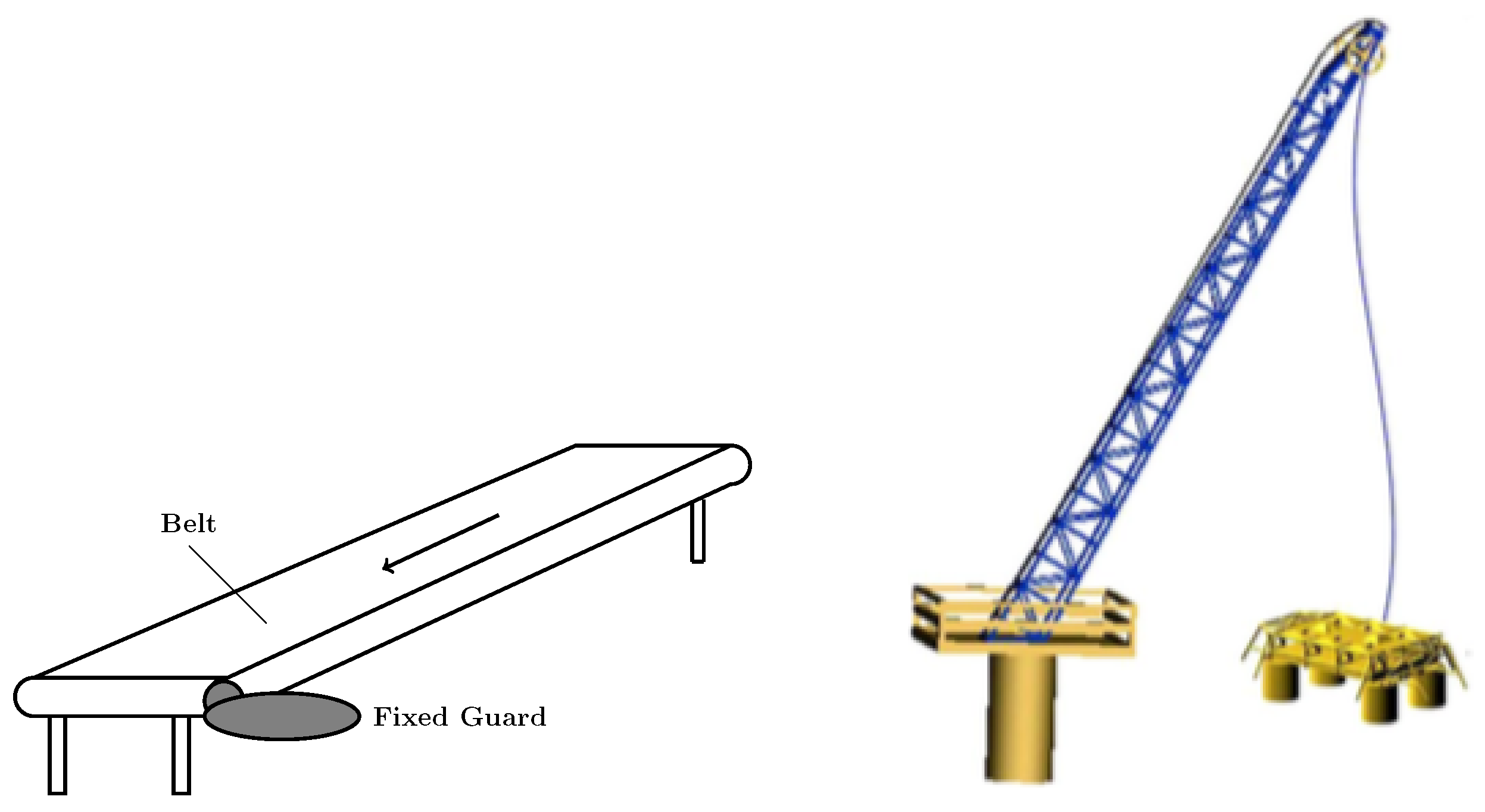
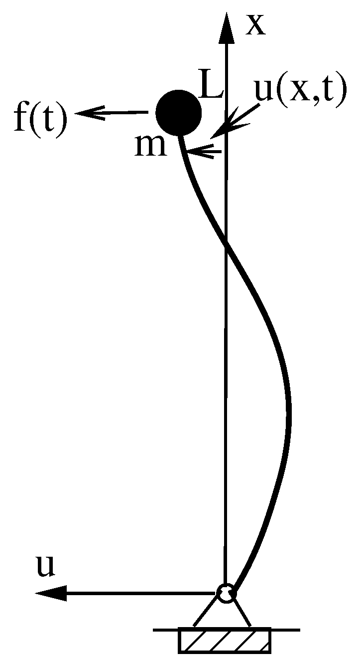
2.1. Cable–Tip–Mass System
- (i)
- The amplitude of is very small.
- (ii)
- is constant all along the cable.
2.2. Asymmetric Peak Detector Model
2.2.1. Definition and Characterization
2.2.2. Bounded-Input Bounded-Output Analysis
- If , then . In fact, we can obtain:
- If , then , for with .
2.3. Asymmetric Peak Detector Boundary Controller
- (a)
- If , then .
- (b)
- If , then . Moreover, from (7) we induce that . So, .
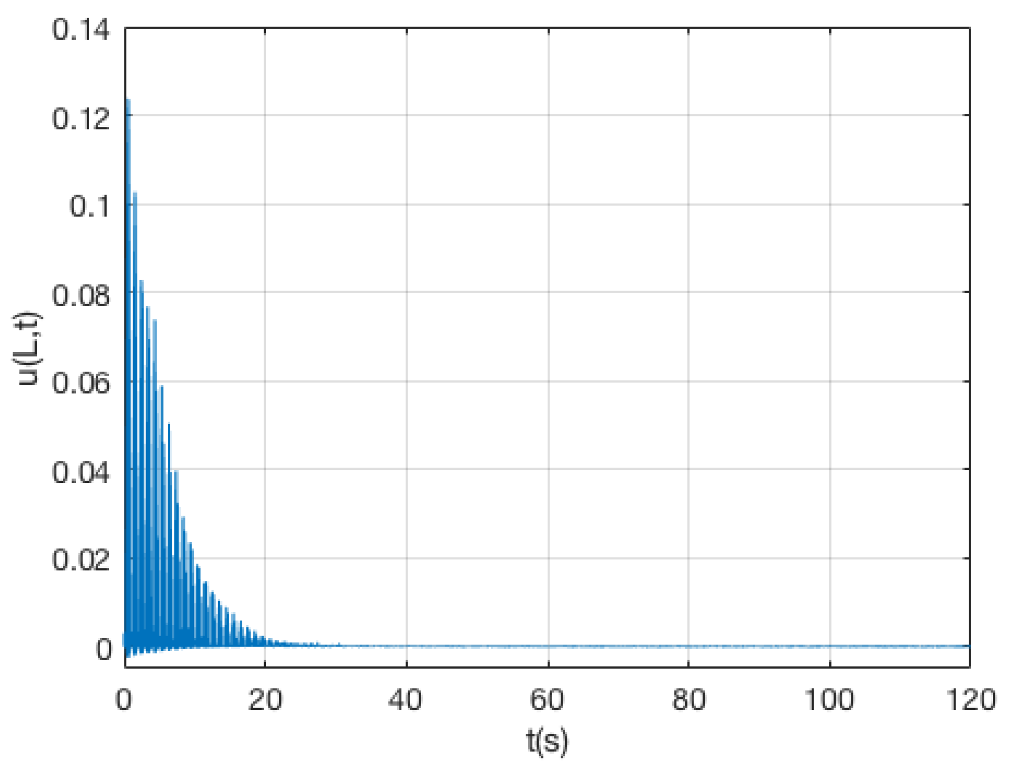
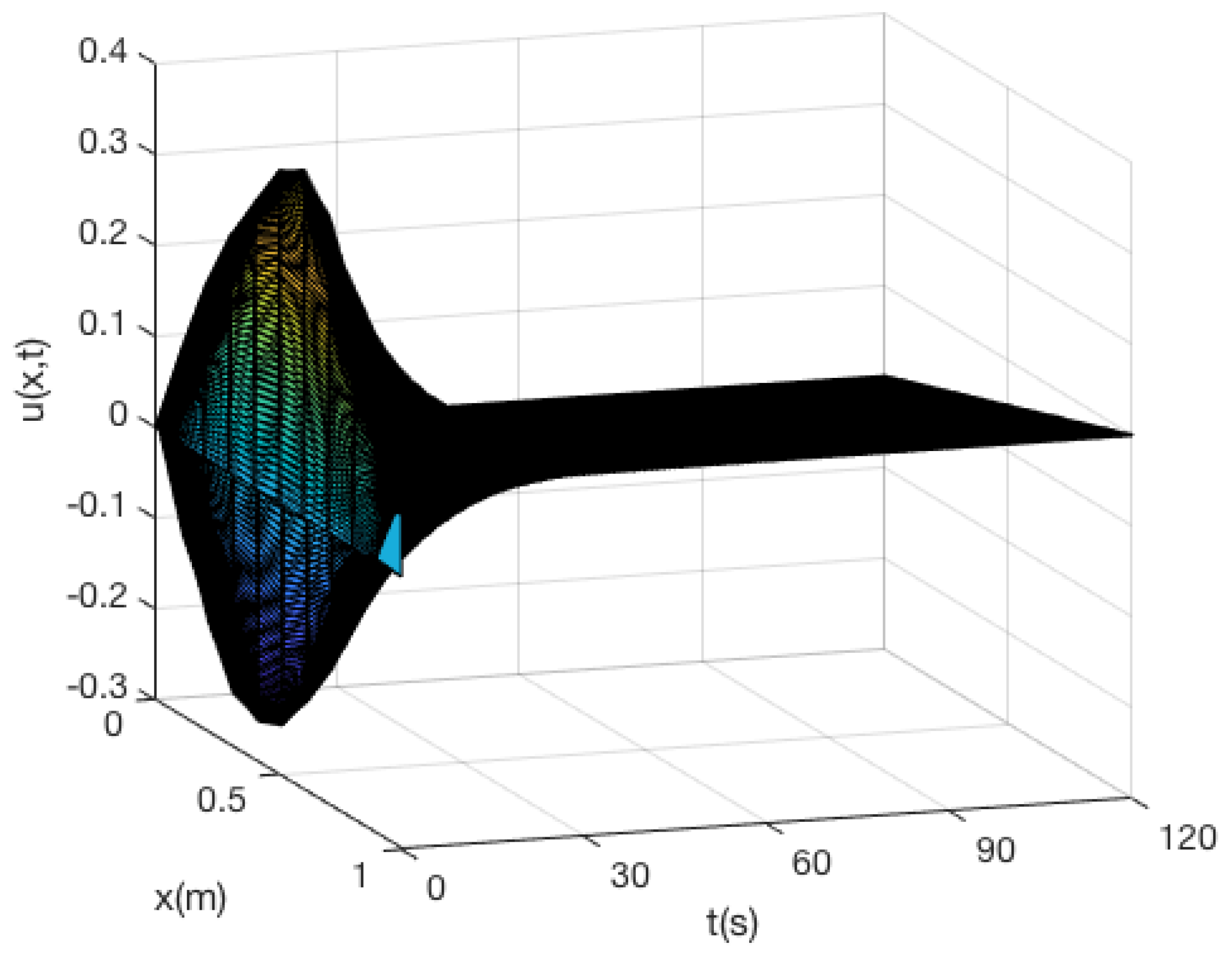
3. Results
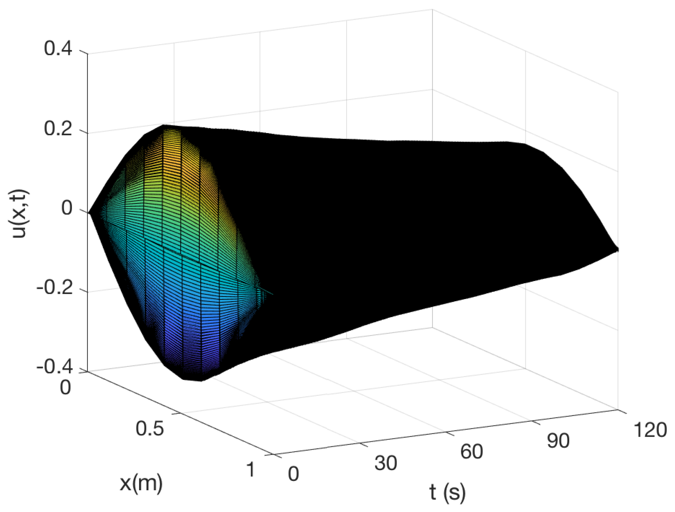
3.1. Unperturbed Case Experiments
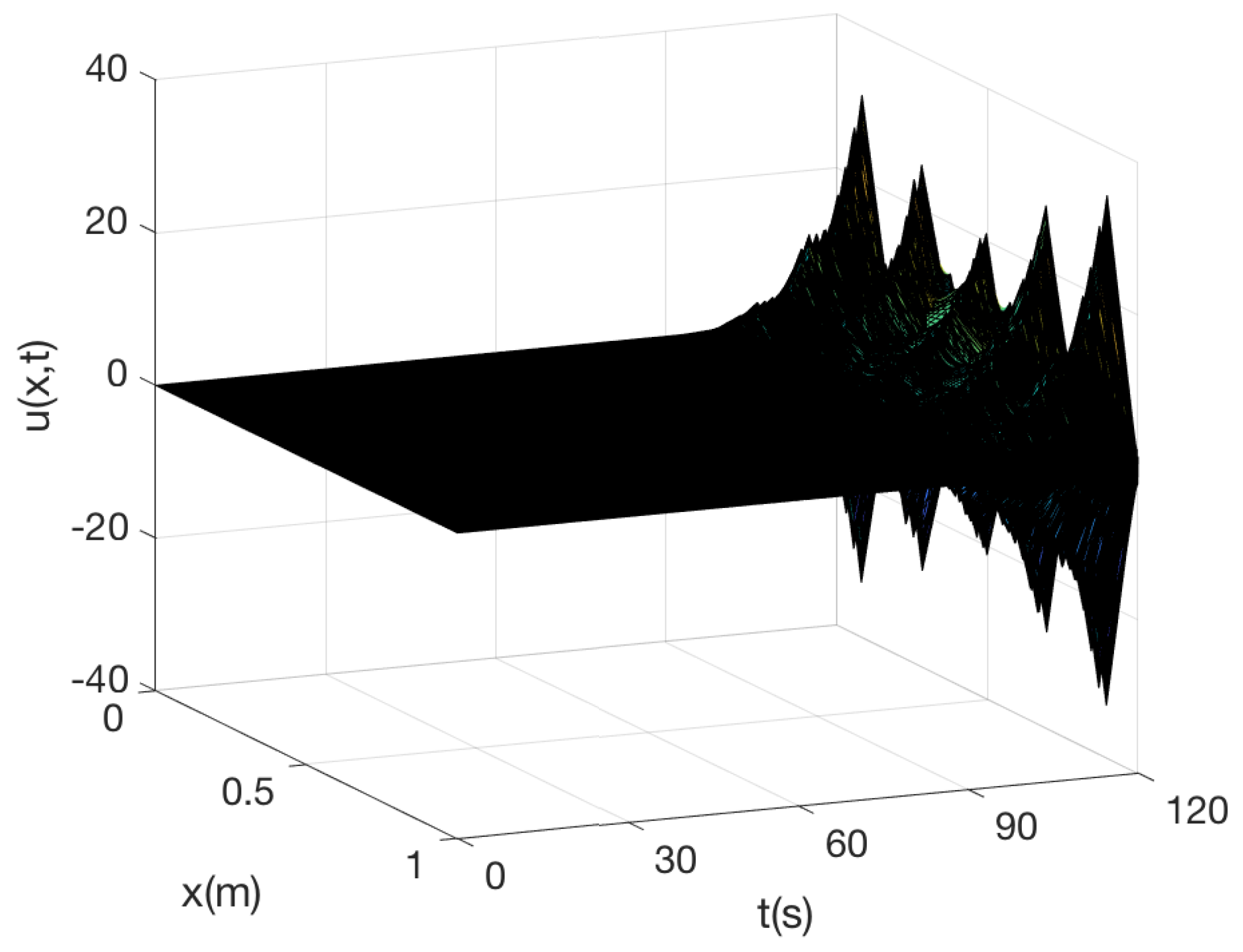
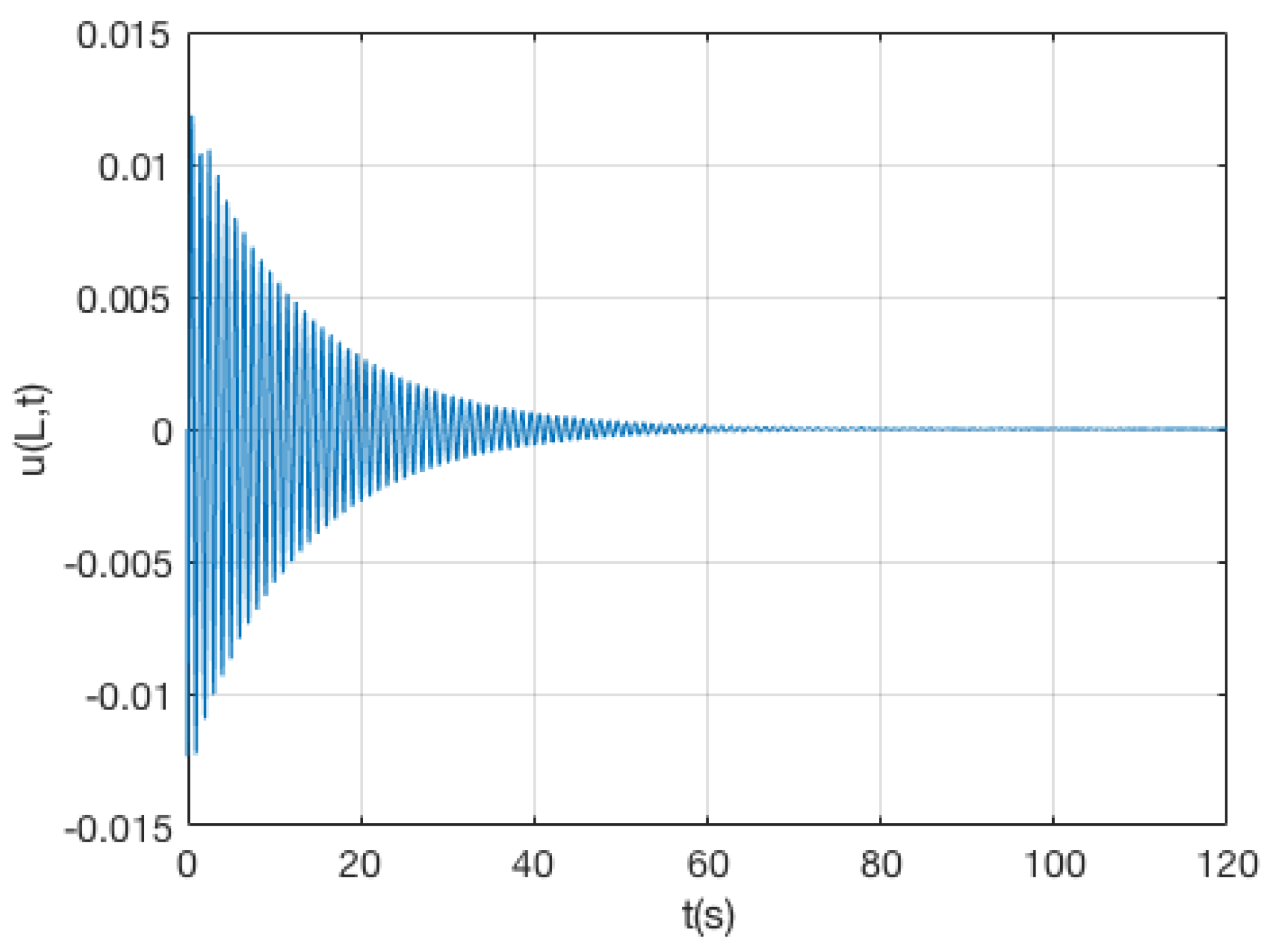
3.2. External Disturbance Case Experiments
4. Discussion
5. Conclusions
Author Contributions
Funding
Informed Consent Statement
Data Availability Statement
Conflicts of Interest
Abbreviations
| PDE | Partial Differenial Equation |
| BIBO | Bounded-Input Bounded-Output |
| D | Diode |
| C | Capacitor |
| R | Resistor |
References
- Morris, K. Control of Systems Governed by Partial Differential Equations; The IEEE Control Theory Handbook; CRC Press: Boca Raton, FL, USA, 2010. [Google Scholar]
- Lasieka, I.; Triggiani, R. Control Theory for Partial Differential Equations: Continuous and Approximation Theories; Cambridge University Press: Cambridge, UK, 2000. [Google Scholar]
- Lagnese, J. Boundary Stabilization of Thin Plates; SIAM: Philadelphia, PA, USA, 1989. [Google Scholar]
- Bensoussan, A.; Prato, G.D.; Delfour, M.; Mitter, S. Representation and Control of Infinite-Dimensional Systems; Birkhauser: Basel, Switzerland, 2006. [Google Scholar]
- Acho, L.; Pujol-Vazquez, G. A boundary control technique to the string-tip-mass system based on a non-symmetric peak-detector model. In Proceedings of the International Conference on System Theory, Control and Computing, Sinaia, Romania, 19–21 October 2017; pp. 759–762. [Google Scholar]
- Krstic, M.; Smyslyaev, A. Boundary Control of PDEs: A Course on Backstepping Desings; SIAM: Philadelphia, PA, USA, 2008. [Google Scholar]
- Luo, N.; Vidal, Y.; Acho, L. Wind Turbine Control and Monitoring; Springer: Berlin/Heidelberg, Germany, 2014. [Google Scholar]
- Dibaj, A.; Gao, Z.; Nejad, A.R. Fault detection of offshore wind turbine drivetrains in different environmental conditions through optimal selection of vibration measurements. Renew. Energy 2023, 203, 161–176. [Google Scholar] [CrossRef]
- d’Andréa Novel, B.; Coron, J.M. Exponential stabilization of an overhead crane with flexible cable via a back-stepping approach. Automatica 2000, 36, 587–593. [Google Scholar] [CrossRef]
- Ballaben, J.S.; Sampaio, R.; Rosales, M.B. Stochastic dynamics of a non-linear cable-beam system. J. Braz. Soc. Mech. Sci. Eng. 2016, 38, 307–316. [Google Scholar] [CrossRef]
- Caverly, R.J.; Forbes, J.R.; Mohammadshahi, D. Dynamic modeling and passivity-based control of a single degree of freedom cable-actuated system. IEEE Trans. Control. Syst. Technol. 2015, 23, 898–909. [Google Scholar] [CrossRef]
- Qu, Z. An iterative learning algorithm for boundary control of a stretched string on a moving transporter. In Proceedings of the 3rd Asian Control Conference, Shanghai, China, 4–7 July 2000. [Google Scholar]
- Bekiaris-Liberis, N.; Krstic, M. Compensation of wave actuator dynamics for nonlinear systems. IEEE Trans. Autom. Control 2014, 59, 1555–1570. [Google Scholar] [CrossRef]
- Morgul, O.; Rao, B.P.; Conrad, F. On the stabilization of a cable with a tip mass. IEEE Trans. Autom. Control 1994, 39, 2140–2145. [Google Scholar] [CrossRef]
- Guo, B.Z. Riesz basis approach to the stabilization of a flexible beam with a tip mass. SIAM J. Control Optim. 2001, 39, 1736–1747. [Google Scholar] [CrossRef]
- Baicu, C.; Rahn, C.; Nibali, B. Active boundary control of elastic cables: Theory and experiment. J. Sound Vib. 1996, 198, 17–26. [Google Scholar] [CrossRef]
- Zhang, F.; Dawson, D.; Nagarkatti, S.; Rahn, C. Boundary control for a general class of non-linear string–actuator systems. J. Sound Vib. 2000, 229, 113–132. [Google Scholar] [CrossRef]
- He, W.; Zhang, S.; Ge, S.S. Adaptive control of a flexible crane system with the boundary output constraint. IEEE Trans. Ind. Electron. 2014, 61, 4126–4133. [Google Scholar] [CrossRef]
- Li, Y.; Aron, D.; Rahn, C.D. Adaptive vibration isolation for axially moving strings: Theory and experiment. Automatica 2002, 38, 379–390. [Google Scholar] [CrossRef]
- Shahruz, S. Boundary control of a nonlinear axially moving string. Int. J. Robust Nonlinear Control 2000, 10, 17–25. [Google Scholar] [CrossRef]
- Zhao, Z.; Liu, Y.; Luo, F. Boundary Control for a Vibrating String System with Bounded Input. Asian J. Control 2018, 20, 323–331. [Google Scholar] [CrossRef]
- Neusser, Z.; Martin, N.; Pelikán, J.; Pawlik, V.; Beneš, P.; Jan, Z.; Volech, J.; Halamka, V.; Machálka, M.; Valasek, M.; et al. Active vibration damping for manufacturing machines using additional cable mechanisms: Conceptual design. Int. J. Adv. Manuf. Technol. 2022, 122, 3769–3787. [Google Scholar] [CrossRef]
- De Queiroz, M.S.; Dawson, D.M.; Nagarkatti, S.P.; Zhang, F. Lyapunov-Based Control of Mechanical Systems; Springer Science & Business Media: Berlin/Heidelberg, Germany, 2012. [Google Scholar]
- Do, K. Stochastic boundary control design for extensible marine risers in three dimentional space. Automatica 2017, 77, 184–197. [Google Scholar] [CrossRef]
- He, W.; He, X.; Zou, M.; Li, H. PDE Model-based boundary control design for a flexible robotic manipulator with input backlash. IEEE Trans. Control Syst. Technol. 2018, 27, 790–797. [Google Scholar] [CrossRef]
- Krstic, M.; Guo, B.Z.; Balogh, A.; Smyshlyaev, A. Control of a tip-force destabilized shear beam by observer-based boundary feedback. J. Control Optim. 2008, 47, 553–574. [Google Scholar] [CrossRef]
- Zhang, S.; He, W.; Li, G. Boundary Control Design for a Flexible System with Input Backlash. In Proceedings of the American Control Conference, Boston, MA, USA, 6–8 July 2016; pp. 6698–6702. [Google Scholar]
- Zhang, H.W.; Wang, J.M. Boundary stabilization of an unstable parabolic PDE with a time-varying domain and the external disturbance. Int. J. Control 2023, 1. [Google Scholar] [CrossRef]
- Kelleche, A.; Saedpanah, F.; Abdallaoui, A. On stabilization of an axially moving string with a tip mass subject to an unbounded disturbance. Math. Methods Appl. Sci. 2023, 46, 15564–15580. [Google Scholar] [CrossRef]
- Homayounzade, M. Adaptive robust output-feedback boundary control of an unstable parabolic PDE subjected to unknown input disturbance. Int. J. Syst. Sci. 2021, 52, 2324–2337. [Google Scholar] [CrossRef]
- Pujol-Vázquez, G.; Acho, L. Semi-active control of flexible structures using acceleration information via peak-detector systems. In Proceedings of the 6th World Conference on Structural Control and Monitoring: 6WCSCM. Centre Internacional de Mètodes Numèrics en Enginyeria (CIMNE), Barcelona, Spain, 15–17 July 2014; pp. 1893–1901. [Google Scholar]
- Floyd, T. Electronic Devices; Prentice-Hall Electronics: Hoboken, NJ, USA, 2005. [Google Scholar]
- Cheng, M.B.; Su, W.C. Boundary stabilization and matched disturbance rejection of hyperbolic PDE systems: A sliding-mode approach. In Proceedings of the American Control Conference (ACC), Montreal, QC, Canada, 27–29 June 2012; IEEE: Piscataway, NJ, USA, 2012; pp. 5360–5365. [Google Scholar]
- Chen, G. Energy decay estimates and exact boundary-value controllability for the wave-equation in a bounded domain. J. Mathématiques Pures Appliquées 1979, 58, 249–273. [Google Scholar]
- Neusser, Z.; Necas, M.; Pelikán, J.; Karlícek, J.; Pawlik, V.; Benes, P.; Machálka, M.; Sika, Z.; Valásek, M. Mechatronic stiffness of cable?driven mechanisms: A study on production machine model. Int. J. Adv. Manuf. Technol. 2022, 123, 431–446. [Google Scholar] [CrossRef]
- Ozbay, H. Introduction to Feedback Control Theory-Chapter 4; CRC Press: Boca Raton, FL, USA, 2000. [Google Scholar]


Disclaimer/Publisher’s Note: The statements, opinions and data contained in all publications are solely those of the individual author(s) and contributor(s) and not of MDPI and/or the editor(s). MDPI and/or the editor(s) disclaim responsibility for any injury to people or property resulting from any ideas, methods, instructions or products referred to in the content. |
© 2023 by the authors. Licensee MDPI, Basel, Switzerland. This article is an open access article distributed under the terms and conditions of the Creative Commons Attribution (CC BY) license (https://creativecommons.org/licenses/by/4.0/).
Share and Cite
Acho, L.; Pujol-Vázquez, G. Enhancing Vibration Control in Cable–Tip–Mass Systems Using Asymmetric Peak Detector Boundary Control. Actuators 2023, 12, 463. https://doi.org/10.3390/act12120463
Acho L, Pujol-Vázquez G. Enhancing Vibration Control in Cable–Tip–Mass Systems Using Asymmetric Peak Detector Boundary Control. Actuators. 2023; 12(12):463. https://doi.org/10.3390/act12120463
Chicago/Turabian StyleAcho, Leonardo, and Gisela Pujol-Vázquez. 2023. "Enhancing Vibration Control in Cable–Tip–Mass Systems Using Asymmetric Peak Detector Boundary Control" Actuators 12, no. 12: 463. https://doi.org/10.3390/act12120463
APA StyleAcho, L., & Pujol-Vázquez, G. (2023). Enhancing Vibration Control in Cable–Tip–Mass Systems Using Asymmetric Peak Detector Boundary Control. Actuators, 12(12), 463. https://doi.org/10.3390/act12120463