1. Introduction
Linear motors are used in rail transport and in many other industrial applications. Compared to other types, the single-sided linear induction motor (LIM) may be used because of its simplicity and low construction cost; its use is widespread and meets the industry’s requirements. It is, therefore, not at all surprising that single-sided LIMs are still the subject of much research aiming to improve their modeling and optimize their design. Despite their simplicity of manufacture and implementation, the modeling and calculation of different quantities of the LIM are not easy tasks. This is mainly due to the magnetic field, which contains a continuous spectrum of space harmonics (SH) [
1], and the nonlinear character of its materials. The requirement of precision within the design process requires the use of accurate numerical methods [
2,
3,
4].
In the design of a three-phase LIM, we are generally confronted with the issue of choosing the physical and geometrical parameters [
5]. It is, therefore, essential to apply electromagnetic modeling, using field theory to develop equations that govern the LIM [
6,
7].
In recent research, a significant number of works on LIMs have been studied [
8,
9]. These studies utilize the finite element method (FEM) to evaluate the thrust and efficiency of LIMs. In other works [
10,
11,
12], researchers have explored innovative secondary designs and calculated typical characteristics, such as the electromagnetic field, using numerical models coupled with analytical ones. Furthermore, one study [
13] presents the influence of different supply modes (both voltage and current) on the characteristic performance of LIMs, considering the end effect inducing the asymmetry of the phase currents. However, it is noteworthy that they did not take into account SH. In a classical rotating induction motor, we try to produce a magnetic field with only one space harmonic. In contrast to this, the condition cannot be obtained in a LIM, which presents a continuous spectrum of SH [
1,
14]. SH generally have a negative effect on the machine, reducing speed, efficiency, and power factor and increasing losses and machine heating. Research works on this question often evoke the SH problem without studying the problem itself [
5,
6]. Few works deal with this problem, though rare references have tried to treat and reduce the effects of SH by designing specific windings or modifying the geometry of the machine [
15,
16], the position of the slots, or the frequency and complex phasors of the currents [
14]. On the other hand, this issue has been well-studied in the case of rotating machines [
17,
18,
19].
A numerical program using FEM can be used to model the electromagnetic behavior of the machine [
20]. Assumptions can be made to consider a “perfect” sinusoidal travelling wave in the air gap, for example, by introducing a slip on the conductivity of the secondary, which is made up of a conductive plate in a rotating induction machine. This is a so-called single space harmonic model. However, due to the non-periodic geometry of the stator armature, the air gap flux density is not periodic. Considering the exact formulation of eddy currents in the secondary by introducing the convective term
allows for the full consideration of the non-periodic behavior of the device and leads to more accurate results. The free finite element software platform Gmsh-GetDP [
21] is used to perform electromagnetic simulation. Connection to an equivalent electrical circuit allows us to deal with the operation at an imposed voltage supply that gives classical performances according to the speed of the secondary [
22].
In addition to specific aspects related to the modeling and characterization of linear induction motors, we focused on the effect of the space harmonics on the machine characteristics and performance. To illustrate this, a comparative analysis of SH presence using two numerical models (single and multiharmonics) was first carried out. The thrust according to the speed generated by the LIM in a real case, taking into account the term representative of SH presence, was compared to the ideal case. This was followed by an assessment of the effect of two machine parameters (pair pole number and conductivity ) on SH presence and the impact of the latter on machine characteristics, including thrust, efficiency, and power factor. The latter depends strongly on physical parameters such as the geometric properties, the pole pair number, permeability, conductivity, etc. In order to enhance the operation and maximize the performance of such machines for a given set of specifications, a suitable choice of optimization parameters should be made. The designer can easily choose some parameters because of their linear dependence on the performance or their invariance. However, some other parameters such as the shape and the number of slots, the pole pair number, the conductivity, etc., cannot be chosen directly due to their nonlinearity. The designer should use an optimization process with a good choice of parameters to select the values of the latter in order to enhance the machine performance.
2. Linear Induction Motor Modeling
A schematic representation (
Figure 1) illustrates a LIM with
primary slots wound to obtain
pole pairs. The secondary is often composed of aluminum and back iron plates, which take the place of the rotor in rotating induction machines.
A kind of characteristic speed
is defined as follows:
where
is the characteristic length attached to the LIM, which represents the total armature length, and
is the supply frequency.
The primary moves at a speed v and a relative speed () are introduced. The product represents, in a way, the synchronous speed of a periodic motor with period . The quantities and the results below were studied and are given according to the relative speed .
In the two-dimensional hypothesis considering an infinite length along the z-axis and neglecting the effect at the ends of the coils, the magnetic potential vector has only one component oriented along the transverse axis . This is due to the source current density imposed along the axis. If we disregard the impact of currents flowing along which encircle the active part of the armature, the influence of the front section of the primary winding, and the impact of the finite axial length of a linear induction motor, are negligible; we can state and .
The simplified model considers a single space harmonic of the magnetic vector potential assumed sinusoidal. The slip is introduced as for rotating induction machines. A two-dimensional time harmonic formulation using magnetic vector potential is adopted for field calculation.
- a.
Model 1: Single harmonic
This model considers that the air gap flux density is periodic and owns one space harmonic, neglecting the effect of all SH. Equation (2) is to be solved using FEM, where the conductivity of the secondary is multiplied by the slip
as for rotating induction machines:
- b.
Model 2: Multiharmonic
In this model, air gap flux density harmonics are considered as they are created by the stator winding. A Lagrangian formulation allows us to express field equations in a frame of reference linked to the stator armature. Due to the smooth geometry of the secondary, no diffraction occurs and, therefore, all the physical quantities have the same time frequency [
23,
24]. The eddy currents in the secondary (conductive plate) are due to movement (
and transformation
terms. The 2D time harmonic formulation yields:
where
is the current density in the slots due to the stator currents.
3. 2D Finite Element Modeling
Two-dimensional finite element modeling, which governs the electromagnetic phenomenon given by magnetic vector potential , is used to solve the two formulations Models 1 and 2. Free software Gmsh-GetDP is chosen to implement the two formulations issued from Model 1 and Model 2. The interesting idea is that the two models can be written in the same formulation in Equation (3) by setting the parameters as follows:
Model 1: and ;
Model 2: and .
This is highlighted in the following screenshot (
Figure 2) of the formulation part of the code.
In Model 1, the field equation is a quite standard Poisson’s equation usually solved in electrical machines. The stiffness matrix is symmetrical, definite, and positive. The storage of the matrix needs the upper non-zero terms and the diagonal. The resolution of the final system is easy and fast. Many resolution methods can be used. The case of Model 2 is quite different. Due to the convective term , the stiffness matrix generated with the formulation is not symmetrical. The storage of the whole matrix is needed. Therefore, the resolution time (CPU) is much longer than for Model 1. This is especially the case for high values that lead to high values of magnetic Reynolds number which leads to numerical perturbations if the characteristic length is too long. The mesh size must be adapted and refined so that these numerical perturbations vanish.
The triangular elements fit to any two-dimensional geometric configuration, which allows a simple discretization of the device. The mesh generated with the finite element program in the Gmsh software is a triangular linear element mesh that is refined in the regions that need accuracy and wide in the other regions, as shown in
Figure 3.
The problem is solved by using GetDP software to perform the implementation of the models.
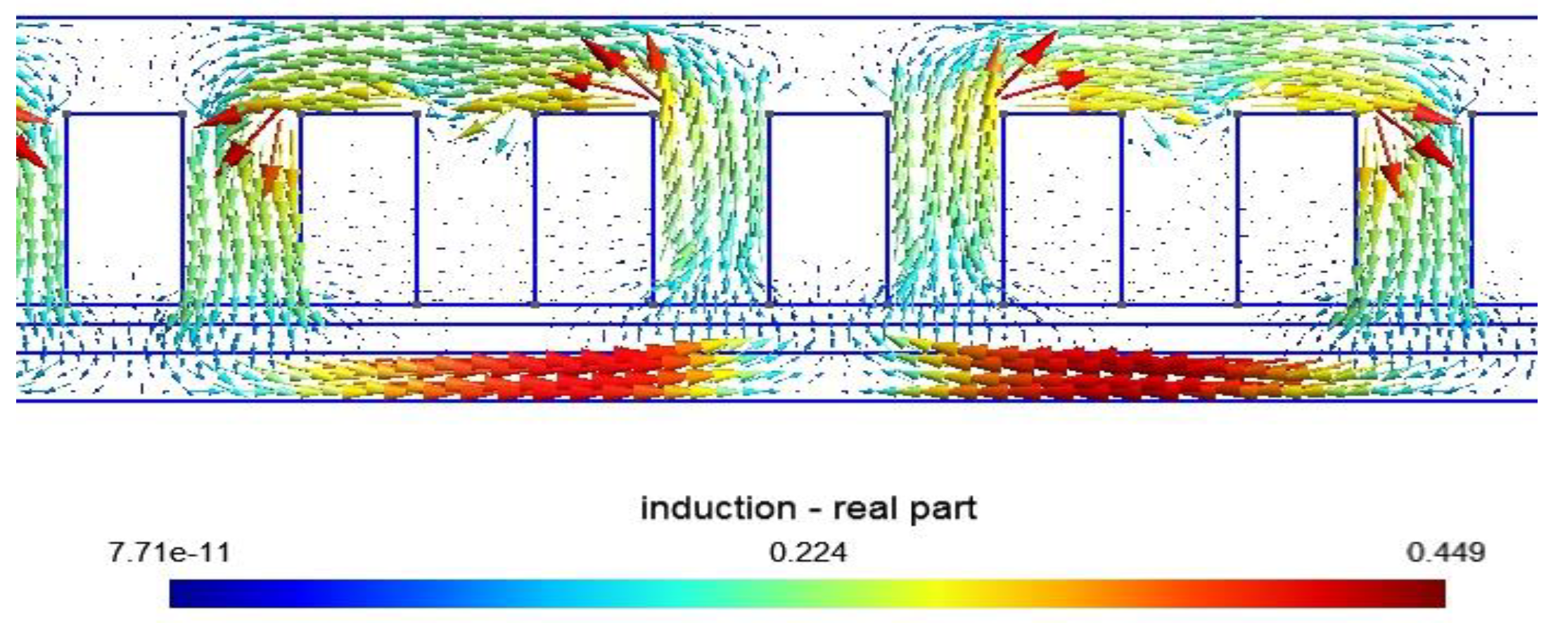
Figure 4 shows the representation of the magnetic flux density vector
derived from the calculated magnetic potential vector
(Equation (8)) in a part of the motor in each node of the mesh. It can be seen that the magnetic circuit channels the flux lines.
The data (
Table 1) of each region for geometrical (dimensions) and physical (permeability
and conductivity
) properties of the studied device are introduced.
Source Current Density Calculation
To calculate the magnetic field and eddy current distribution in each region, the primary current density in the slots of a two-pole single-layer three-phase winding is defined using a connection matrix
that links the phase currents and the stator slots. The expression given below is related to one pole pair and can be duplicated
times for a winding of
pole pairs to obtain the whole connection matrix
.
When the single-layer winding machine is supplied by sinusoidal three-phase currents, the ampere-turns
in the slots can be calculated using
where
is the number of turns per slot and
denotes the phase currents.
The stator current density in the slots, used in Equations (2) and (3), is defined as the sum of slot current densities due to the ampere turns in the slots.
4. Connection with Equivalent Electric Circuit
In this paper, a simplified equivalent electric circuit (EEC) is considered to evaluate the performance of the machines under a voltage supply [
25,
26]. Neglecting the iron losses and assuming the first harmonic hypothesis, the EEC used is shown in
Figure 5.
- -
is the stator resistance, which can be determined using the classical analytical formula;
- -
is the primary inductance (i.e., the magnetizing inductance);
- -
is the leakage inductance expressed in the secondary frame, which depends on the slip;
- -
is the equivalent resistance expressed in the secondary frame, which depends on the slip.
Finally, is the equivalent operational impedance of the machine in the hypothesis of a monoharmonic model. Such a model can be used in connection with the single harmonic model (Model 1). In the case of Model 2, there is no need to go into detail for . The most important thing is to determine the operational impedance and evaluate the stator current with the circuit model equivalent to voltage supply.
4.1. Voltage Supply and Electric Parameters’ Identification
The approach adopted for the calculation of the EEC parameters uses both FEM and the analytical method presented in this paper [
27]. When the machine is supplied with a three-phase voltage,
given by:
where
is the amplitude of the three-phase voltage.
The calculation of the operational impedance is performed as follows:
- -
Calculate the phases fluxes by using magnetic vector potential in the slots and winding matrix.
- -
Calculate the emfs: .
- -
Calculate the impedances with .
This method has been widely used for the modeling of rotating induction machines even for the single harmonic model or multiharmonic model [
28]. The operational impedances for the three phases are equal due to the balance of the phases in conventional induction machines. The calculation can be performed in one of the stator phases. However, in the case of LIM, the imbalance of the phases requires performing the calculations on the three phases. Indeed, the phases are not balanced, and nor are the impedances and the stator currents that are shown below [
29].
4.2. The Phase Currents
The stator phase currents
for each value of the speed
v can then be determined as follows:
The calculation of the stator currents with (7) allows us to perform the field calculation given by Equations (2) and (3) for Model 1 and Model 2, respectively. This is the final right computation of field distribution in the machine for the considered speed at fixed voltage [
6].
In this step, the performance of the machine can be calculated either using the field equation (force) or input power (input voltage and currents).
4.3. Force Calculation
In the two-dimensional hypothesis, the magnetic potential vector
has a single component
oriented along the transverse axis
, and its value depends only on the
and
coordinates. The magnetic flux density is given by the gradient of
as follows:
where
and
denote the unit vector in the cartesian references.
The tangential component
of magnetic flux density creates normal forces in the linear induction motor, whereas the normal component
generates the motor thrust. In a 2D approximation, the global Lorenz force
is written as follows:
where
is the length of the machine in
-direction. In the case of a time harmonic formulation, the complex representation of electromagnetic quantities is used. The average values of tangential and normal components of the force (
and
) are given by the following Formula (10a,b):
denotes the “real part of”.
4.4. Power Factor and Efficiency
The knowledge of the input power from the circuit equation and the calculation of the losses in the stator
winding and secondary
makes it possible to evaluate the efficiency
and the power factor
by using
denotes “transposed part of”, and denotes: “conjugate part of”.
5. Results and Discussion
The LIM, with the characteristics given in
Table 1, is modeled using FEM. First, the force–speed characteristics calculated with the two models are presented, compared, and discussed. In a second step, a parametric study is performed to highlight the SH effect of some parameters on output performance.
5.1. Illustration of Space Harmonics Effect
Figure 6 illustrates the difference between force–speed curves obtained by, respectively, the single-harmonic and multiharmonic models in case of a 12-pole winding (
. The force, in the case of Model 1, decreases with the relative speed
and drops to zero at synchronous speed (
. In the case of Model 2, the force is lower than in the first model case; this is due to the SH presence effect, and the force vanishes to zero at a speed below synchronous speed
. This behavior is coherent since Model 1 considers one harmonic and uses the slip parameter, whereas the multiharmonic model accounts for the presence of all SH. Some of them create a negative force so that the total force is zero below synchronous speed. For this model, we talk about synchronous speed of the fundamental wave, but in practice, there are an infinity of waves travelling at different speeds in the two directions.
5.2. Impact of Pole Number
In the following, all the results are presented according to the relative speed , which means that for different pole numbers, the synchronous speed changes with the inverse of pole number.
The case presented in
Figure 6 is optimistic because it considers six pole pairs. The end effects are supposed to be low or negligible. If the number of poles decreases, the end effect increases and the distortion of the air gap flux density is important.
Figure 7 presents the force–speed characteristics for the same machine with different pole numbers, as obtained with the two models. The geometry of the stator is conserved. The winding changes, and the number of slots per pole and per phase changes from
for
(corresponding to a two-pole winding) to
for
.
The force curves shown in
Figure 7 decrease with the velocity from maximal force at standstill and vanish to zero close to synchronous speed. The force obtained by Model 1 (solid lines) is always higher than that obtained by Model 2 (dashed lines) because Model 1 is optimistic and does not consider harmonics. In addition, we can see that for
the force speed characteristic has a very disturbed shape and low values compared to the provisions of Model 1.
The consequence of the assumptions made by Model 1 is that the performance is better in terms of force and also in terms of efficiency and power factor (
Figure 8 and
Figure 9). We can see that the shape of these curves is similar to those of the induction machine and the behavior is correct. The power factor is low for high pole numbers as well as efficiency. Such results are to be taken with much caution because of the strong assumptions. A full model that considers SH is required.
However, it can be seen that for high pole numbers (), the results given by Model 2 are close to those of Model 1. This means that if the pole number is too high, the end effects become reduced and air gap flux density presents a pseudo-sinusoidal shape. In this case, a single harmonic model could be sufficient to evaluate the machine performance.
Without SH presence (Model 1), the efficiency decreases with the number of pole pairs (
Figure 8), whereas with SH presence (Model 2), the efficiency has a maximum value for
and the lowest one for
and
(
Figure 8).
Except for
, where it decreases continuously, the power factor (
Figure 9) increases with relative speed
, reaching a maximum and dropping at synchronous speed to 0.04 in the case without SH presence and to around 0.1 in the case with SH presence. In Model 1, the power factor has the maximum for
and decreases according to the pole pair number p, whereas in Model 2, as for the efficiency, the maximum is obtained for
working velocity near the synchronous speed.
5.3. Effect of Electrical Conductivity
The electrical conductivity is also a property that affects the features of the LIM, as shown in
Figure 10,
Figure 11 and
Figure 12. The obtained curves have classical shapes with a maximal value that depends on the relative speed. The thrust (
Figure 10) increases with the conductivity (iron, steel, aluminum, and copper) and presents an optimal value for rotating induction machines. It is clear that increasing the conductivity often increases the eddy currents in the secondary; this leads to the increase in the thrust calculated using the Lorenz formula (
) due to dependency on the current density. It can be expected that for lower conductivities, the maximum values are reached for negative speeds that are not represented in these figures.
It can also be seen that in Model 2, as in Model 1, the thrust increases with the conductivity. At start-up (for lower speed values), the efficiency and the power factor (
Figure 11 and
Figure 12) often decrease with the electrical conductivity. Meanwhile, the power factor varies in a nonlinear manner, increasing first from the lowest to the maximum efficiency for, respectively, the conductivities 2 to 10 MS/m, and decreases before the values. The space harmonics’ presence has practically no effect in this part.
At working velocity ), according to the conductivity, the efficiency increases in Model 1 and the power factor increases in Models 1 and 2 with a good value for copper. Meanwhile, the efficiency in Model 2 presents good values for steel and aluminum and decreases for copper and iron.
6. Conclusions
Linear induction machines are increasingly used in all fields: in production units (horizontal and vertical carts), in transport (magnetic levitation trains), and in other sectors such as non-destructive testing (NDT) equipment used to assess the state of health of pipelines, and so on. Minimizing energy consumption, reducing energy losses, and minimizing design and production costs are requirements that must be taken into account when designing these machines. The designer is faced with the problem of choosing the optimum geometric and physical parameters to satisfy these requirements. Given the nonlinearity of the dependence of some of these parameters on the desired characteristics, an analysis using FEM-type direct calculation models is necessary. The FEM model under Gmsh-GetDP is implemented and used to determine this dependency. The dependency analysis enables the designer to make the right choice of parameters, so they can incorporate them into an optimization process to meet the above requirements.
This work was focused on the study of the SH impact of the different machine parameters on the LIM characteristics. Single-harmonic and multiharmonic models were developed in MATLAB and the Gmsh-GetDP environment, which enabled a study of SH effects of a three-phase single-sided LIM. The electromagnetic thrust was calculated using FEM (Models 1 and 2). The parameters’ effects on the different characteristics of the machine were analyzed and discussed.
The multiharmonic model showed that the SH are not taken into account in the single-harmonic sinusoidal model, leading to significant errors.
The thrust increases with the pole pair number in line with the conductivity.
The SH presence effect is related to the displacement speed ; it is absent or very weak at low speeds and significant near the synchronizing speed, thus cancelling the thrust before the synchronous speed and increasing machine slip (s).
SH reduces the power factor and the efficiency, which have a complex nonlinear correlation with the pole pair number, and they increase with the electrical conductivity.
Increasing the pole pair number increases the operation velocity up to the synchronization speed, reduces the harmonics’ presence, and makes the LIM behave as an induction machine.
At working velocity ), the machine presents a good power factor for aluminum and copper materials and a good efficiency for aluminum materials.
The machine parameters such as secondary conductivity and number of pole pairs play an important role in the performance of linear induction machines. Because of the complex nonlinear correlation between the machine parameters and the machine performance, like speed, power factor and efficiency, it is difficult to directly choose the optimal parameters. Thus, to enhance the machine performance and thereby achieve the optimal operation of such a machine for a given specification, it is necessary to use optimization techniques.


