Article

Characterization of a 3D Printed Endovascular Magnetic Catheter

by
Mohammad Hasan Dad Ansari
1,2,3,*,†,
Xuan Thao Ha
1,2,3,
Mouloud Ourak
3,
Gianni Borghesan
3,4,
Veronica Iacovacci
1,2,
Emmanuel Vander Poorten
3 and
Arianna Menciassi
1,2
1
The BioRobotics Institute, Scuola Superiore Sant’Anna, 56025 Pontedera, Italy
2
Department of Excellence in Robotics & AI, Scuola Superiore Sant’Anna, 56025 Pontedera, Italy
3
Department of Mechanical Engineering, KU Leuven, 3000 Leuven, Belgium
4
Flanders Make @ KU Leuven, 3000 Leuven, Belgium
*
Author to whom correspondence should be addressed.
Current address: Istituto Italiano di Tecnologia, Viale Rinaldo Piaggio 34, 56025 Pontedera, Italy.
Actuators 2023, 12(11), 409; https://doi.org/10.3390/act12110409
Submission received: 3 October 2023 / Revised: 29 October 2023 / Accepted: 30 October 2023 / Published: 1 November 2023
(This article belongs to the Special Issue Soft Actuators for Medical Robotics)

Abstract

:
Minimally invasive endovascular procedures rely heavily on catheter devices. However, traditional catheters lack active steering requiring considerable skill on the surgeon’s part to accurately position the tip. While catheter tips could be made steerable using tendon-driven and Pneumatic Artificial Muscle (PAM) approaches, remote magnetic actuation is uniquely suited for this task due to its safety, controllability, and intrinsic miniaturization capabilities. Soft composite magnetic materials feature embedding distributed magnetic microparticles compared with attaching discrete permanent magnets proving beneficial in steerability and control. This work demonstrates the fabrication of a soft hollow magnetic tip that can be attached to a catheter to make the assembly steerable. The catheter tip is extensively characterized in terms of bending hysteresis, bending force, and dynamic response. The catheter showed average hysteresis between 5% and 10% and bending forces up to 0.8 N. It also showed a good dynamic response by changing its bending angle in <200 ms under a step response.

1. Introduction

Minimally invasive procedures through endovascular interventions carried out using catheters have been reported to confer lower morbidity than open surgical techniques while preserving the efficiency [1]. The use of catheters is becoming increasingly common to access deep and remote anatomic regions through the body lumina for clinical procedures [2] like stent placement [3], laser ablation [4], and imaging [5] among others. However, such catheters remain difficult to use in tortuous paths due to limited tip control. When the operator rotates a 150 cm long traditional catheter, the distal tip should also rotate accordingly despite being looped around the body [6]. However, the distal tip may not always respond as expected which may possibly lead to inaccurate positioning of the catheter tip. This hurdle can be overcome by having catheters with steerable tips usually by using technologies like cable or tendon driven steering [7,8,9], shape memory effect [10], Pneumatic Artificial Muscles (PAMs) [11], hydraulic [12], and pre-curved concentric tubes [13]. Cable or tendon driven steering remains the most widely used catheter actuation technology because of the simplicity it offers in design and fabrication. However, such catheters tend to be stiff due to the need for a backbone to prevent buckling and due to the presence of tensioned cables, and are difficult to miniaturize and control precisely [14].
An alternative way of actuating the catheter tip is by using magnetic fields which could help in performing complex coordinated motion in Three Dimensional (3D) space in a safe, highly controllable, and remote fashion [15,16,17,18]. Magnetically actuated catheters have been reported in the literature as far back as 1951 using custom electromagnetic navigation systems [19]. In 2002, researchers attached a single permanent magnet to the tip of a 7 French (F) ablation catheter that was used to perform navigation and ablation in dogs and pigs. A commercial magnetic navigation system (Telstar; Stereotaxis, Inc., St. Louis, MI US) consisting of an array of superconducting electromagnets surrounding the torso of the animal was used to generate magnetic fields that try to align the catheter parallel with it [20]. However, there were some misalignments and navigation to a particular target required multiple adjustments of the magnetic field. Nonetheless, the positional accuracy was reported to be <1 mm and the feasibility of using magnetic fields as a means of remote actuation of a catheter was established [20]. However, using bulky magnetic navigation systems significantly affects quick access of the patient to the surgeon in case of an unforeseen emergency. Further, bulky magnetic navigation systems, like MRI machines, would require specialized surgical rooms to avoid any unwanted interactions with other metallic tools typically used in the surgical room and would increase equipment capital and infrastructure costs.
Taking the idea forward, multiple-point magnetic actuation over the length of the catheter was reported [21]. Multiple permanent magnets embedded along the length of the catheter give the option of distributed control. By controlling how each of the magnet interacts with the external magnetic field, patient-specific magnetic catheters could be designed. While using distributed magnets along the length has its advantages, it is also limited in terms of miniaturization due to the finite size of the embedded magnets required to deflect the catheter under applied magnetic fields. There are also concerns that the embedded rigid magnets at the tip of catheters and guidewires could break off leading to undesired clinical problems like blockage of arteries [22].
To overcome these limitations, magnetically actuated soft catheters have been proposed by Kim et al. [23], among others. Instead of using discrete magnets, magnetic microparticles were uniformly dispersed throughout their soft polymeric body. The use of magnetic microparticles as distributed actuation sources enables the miniaturization of magnetic catheters and guidewires to sub-millimeter scale. While soft bodied catheters could provide less traumatic navigation, even at acute angles, and could reduce injury related complications due to their inherent compliance [24], so far only magnetic guidewires for cerebrovascular applications have been shown [23]. In contrast, a hollow catheter gives the ability to introduce other functionalities such as drug delivery, Intravascular Ultrasound (IVUS), stents or coils which may be needed to perform specific tasks during the surgery. The hollow lumen can also help in introducing localization and shape sensors like Fiber Bragg Grating (FBG) and Electro-Magnetic (EM), which can accurately determine the pose of the catheter tip and therefore may be needed for accurate positioning and for providing feedback for better control. The characterization in this paper could be helpful for developing magnetic catheters for other endovascular applications as well.
The main contributions of this paper are:
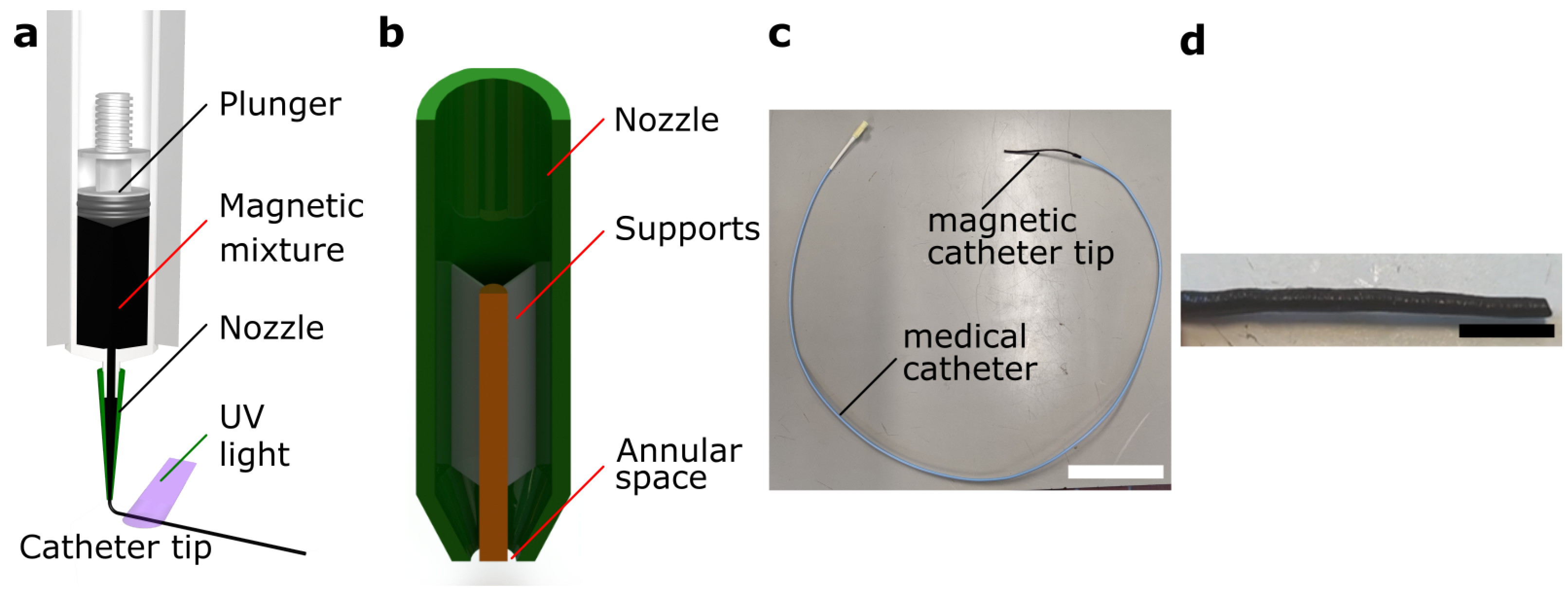
  • Custom fabrication of a soft hollow magnetic catheter tip using mold-free extrusion.
  • Numerical modeling of the steerable tip bending and its verification, required for the prediction of its bending.
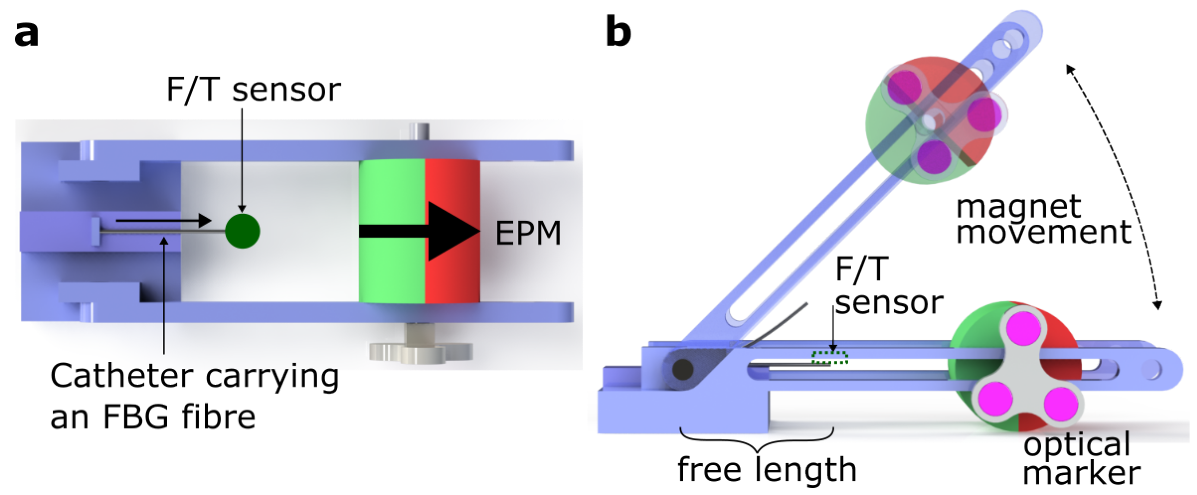
  • Characterization of bending hysteresis and bending forces. Through such characterizations, a control strategy can be developed.
This paper is organized as follows: Section 2 explains the design and fabrication of the custom magnetic catheter tip and its design. Section 3 details the magnetic actuation theory and the numerical modeling of the catheter bending. Section 4 describes the bending characterization of the magnetic catheter tip with respect to its hysteresis, bending forces it can apply, and its dynamic response. Section 5 concludes the paper summarizing the main results and possible future directions.

2. Fabrication of the Magnetic Catheter

A custom made magnetic catheter (MC) was developed combining a catheter body with a hollow magnetic tip which is composed of a soft polymer (UV electro 225-1, Momentive, Cologne, Germany) embedded with Neodymium Iron Boron (NdFeB) magnetic particles (MQP-15-7-20065, Magnequench GmbH, Tüubingen, Germany). It was prepared by extruding a mixture of the polymer and magnetic particles through a custom nozzle and curing it using high intensity Ultra-violet (UV) light (Figure 1). The preparation of the magnetic mixture is described in detail in [25]. The extruded structure was then magnetized along the axial direction using an Impulse Magnetizer (T-Series, MAGNET-PHYSIK, Cologne, Germany). A UV-curable polymer is used because it gives the option for fast curing which is necessary to extrude hollow structures without the extruded material collapsing on itself. NdFeB is selected as the material for providing magnetic capabilities because it is hard magnetic, and has the highest remanent magnetization, and as such provides the strongest magnetic actuation.
The resulting bendable catheter tip is a hollow cylinder of 7 mm length, 2.3 mm (6.9 Fr) outer diameter and 0.9 mm (2.7 Fr) inner diameter lumen. An internal lumen of ≈1 mm is important to allow the introduction of other functionalities like guidewires, IVUS, or targeted medicines through it. Because of the extremely high viscosity of the magnetic mixture, it becomes difficult to extrude it through orifices of less than 500 μ m. Therefore, the overall diameter of the magnetic catheter turns out to be 2.3 mm. The fabricated catheter tip is glued to the distal end of a 4 Fr (1.4 mm) medical catheter. The magnetic particles give the catheter tip a distributed axial magnetization which enables remote magnetic actuation.

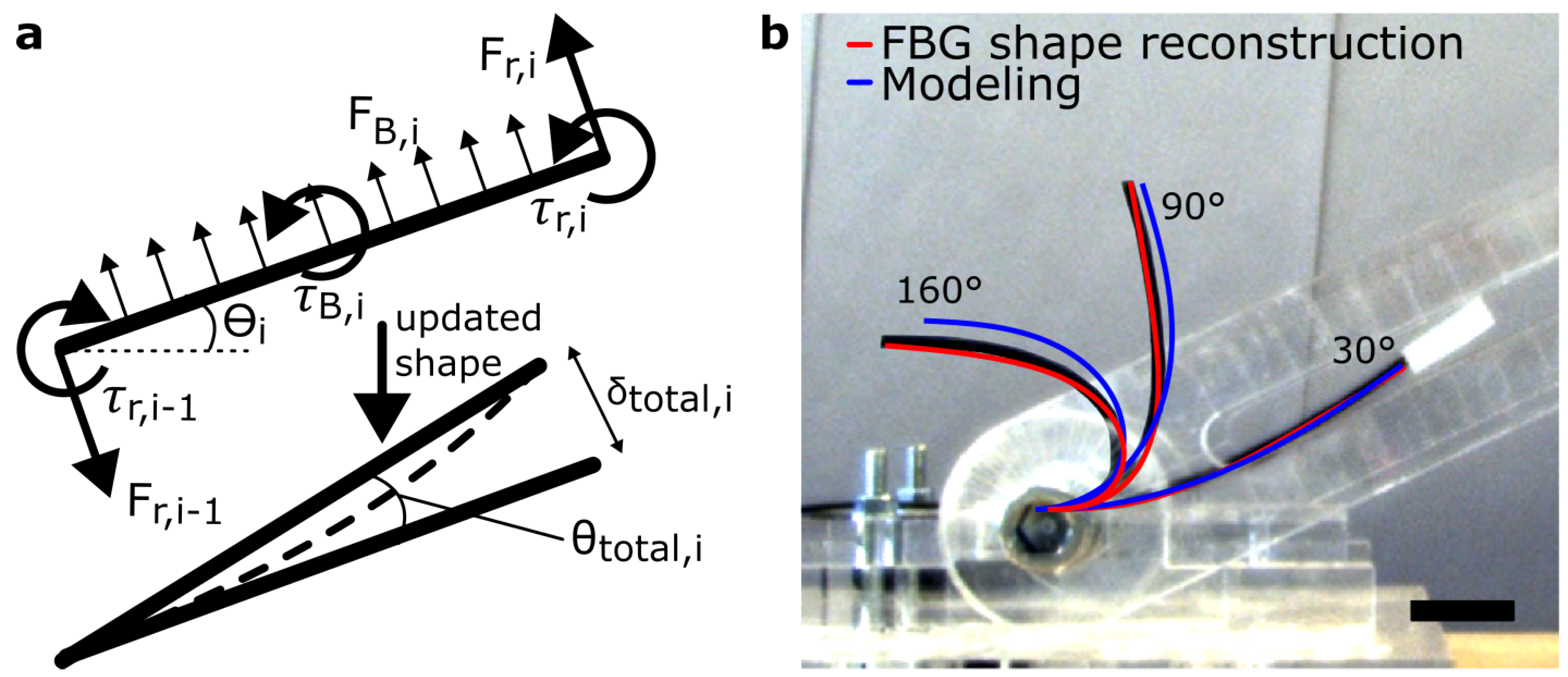
3. Mathematical Modeling of Catheter Bending

As the position of the External Permanent Magnet (EPM) changes with respect to the magnetic catheter, the magnetic fields experienced by it also vary both in direction and intensity. Therefore, the magnetic fields were numerically modeled to predict their intensity and direction in space around the EPM. This information was used to predict the bending behavior of the magnetic catheter through numerical modeling when the EPM is moved along an arc around it.

3.1. Fields around an External Permanent Magnet

The EPM is cylindrical in shape (7 cm length and 6 cm diameter), diametrically magnetized with a 1 cm through hole along its axis which is used for mounting it on supporting structures. As reported in the literature [26], a permanent magnet can be approximated as a magnetic point dipole when the working distance is beyond the radius of its minimum bounding sphere. In this case, the radius of the minimum bounding sphere is 4.6 cm. For endovascular applications the working distance should be more than ≈15 cm to take into account the chest anatomy of the patients. Hence, we have chosen 15 cm as our working distance which is bigger than the radius of the minimum bounding sphere and therefore, the EPM can be assumed to be a point dipole for the purpose of calculating the fields at a point in space given by:
B ( r ) = μ 0 4 π 3 r ( m 1 · r ) | r | 5 m 1 | r | 3
where μ 0 is the vacuum permeability constant, B is the magnetic flux density, r is the position vector of the point in space from the EPM, m 1 is the magnetic moment of the point dipole, and · represents the dot product of two vectors. This equation gives us the magnitude and the direction of the magnetic field around the EPM.
The magnitude of the magnetic field drops considerably with distance from the EPM. Not only the field magnitude itself but also the field gradient magnitude increases considerably when getting closer to the EPM. When the catheter is placed close to the EPM, the magnetic field applies a torque on the catheter tip to align it with itself, and the magnetic field gradient pulls the catheter tip towards the EPM. A dipole with moment m 2 at a position vector r where the magnetic field is B will experience a force given by (2) and a torque given by (3).
F = ( m 2 · B )
τ = m 2 × B

3.2. Modeling the Soft Magnetic Catheter

The magnetic steerable tip was divided into 1mm segments length-wise which were modeled as in-extensible cantilever beams on which the magnetic field applies a force and a torque as formulated in (2) and (3). Only a planar model was considered as the deflections of the magnetic catheter lie in the X-Y plane and the EPM could also be modeled as a point dipole in this plane. There are a few assumptions in the developed model. The magnetic catheter is assumed to have a uniform cross-section. It is assumed that each segment is slender and its deflection minuscule. Each segment is also modeled as a straight line. The Free-Body Diagram of each segment is shown in Figure 2a with the cantilever being anchored at the proximal end. The magnetic force was modeled as a distributed load along the length of the segment. Torque was modeled to be acting at the middle of the segment. Further, each segment i exerts a reaction torque τ r and force F r on the segment i 1 immediately preceding it. For each force F and torque τ acting on the segment of length L at a point at a distance a from the anchored end, the deflection δ at the free end is calculated using (4), or (5). For each distributed force w, the deflection at the free end is calculated using (6).
δ F = F a 2 6 E I ( 3 L a )
δ τ = τ a 2 2 E I
δ w = w L 2 8 E I
argmin I = i = 1 16 n = 1 N ( Θ n , 10 i Θ f b g , n , 10 i ) 2 N / 16
Θ f b g are the angles derived from the reconstructed shape of the catheter using an FBG fibre (Section 4.1) and are taken as the ground truth. Initially, the catheter was assumed to be straight horizontally and aligned with the axis of the EPM (rest state). The global reference frame is defined such that the X-axis is along the catheter at rest state. All the deflections occur in the X-Y plane with the Z-axis out of the plane. The global angle Θ i for each segment is tracked from the X-axis of the global coordinate frame. Since all the segments are aligned horizontally initially, Θ i for i = 1 : N is 0 . The deflections from each force/torque component are summed to obtain δ t o t a l , i , which was then used to calculate the angle of deflection θ t o t a l , i . The Young’s modulus E of the magnetic catheter was experimentally measured [25]. Assuming the segment length remains constant, the segment shape was then updated to be a straight line deflected by θ t o t a l , i from the previous shape. EPM angles ( α ) starting from 0 and in steps of 10 were considered. For each α , the modeling starts with the most distal segment, i.e., i = N for which τ r , N and F r , N are 0, as there is no segment beyond it to exert any reaction torques and forces. θ t o t a l , N was calculated and added to Θ N . Similarly, θ t o t a l , i was calculated for each subsequent segment moving inwards from the most distal segment. Before moving to ( i 1 ) th segment, θ t o t a l , i was added to Θ j for j = i to N. Continuing until i = 1 , the first iteration was completed and the shape of the magnetic catheter updated. Since the magnetic field produced by the EPM is non-uniform, the forces and torques acting on the magnetic catheter will now be different in the new configuration and hence an iterative computation is needed until the system converges below a certain threshold. In this work, iterations were repeated until the greatest change across all Θ i for i = 1 to N between iterations was < 0 . 1 . Since during fabrication, the magnetic catheter tip becomes deformed from a round shape to a slightly flattened shape more resembling an ellipse due to gravity, the cross-section of the hollow space and the magnetic catheter was assumed to be ellipse and area moment of inertia I was calculated as I c = 2.3 × 10 12 . Since this is just an approximation, a more fitting value was calculated by optimizing I around I c . The RMSE of Θ with respect to Θ f b g for each α was calculated and its mean was taken as the minimization cost function (7). While the resulting mean RMSE with I c was 18.2 , it was reduced to 5 . 0 with the optimized I o = 3.4 × 10 10 and the results of this parameter optimization are shown in Figure 2b for three different α 30 , 90 , and 160 .
The magnetic catheter is assumed to have a uniform cross-section in this model, which may not be true. Further, the assumptions of the cantilever beam theory that the beam has to be slender and the deflections minuscule may not necessarily be true for each segment. The representation of each segment as a straight line is also not true whenever there is any bending involved. Despite these assumptions, the proposed model works well for predicting the shape of the magnetic catheter for each EPM angle.

4. Bending Characterization of the Magnetic Catheter

The magnetic catheter was characterized for its bending response when the EPM was moved along a circular arc of fixed radius around and in the vertical plane containing the catheter. The characterization test system is shown in Figure 3. The EPM was attached to a hinge using an arm on each side such that it could move in an arc around that hinge. The magnetic catheter was clamped at the hinge such that a section of it (free length) towards the EPM becomes actuated by it. The EPM was manually moved along the arc which resulted in bending of the magnetic catheter. The angular position of the EPM and the response of the magnetic catheter were recorded and analyzed to derive its bending characteristics. To characterize the bending force of the magnetic catheter, its tip was restrained by a Force/Torque (F/T) sensor from bending while the EPM was moved along an arc and the forces applied by the magnetic catheter were recorded.

4.1. Sensors

The angle of the EPM was recorded using a six-Degrees of Freedom (DOF) real-time optical tracking system (fusionTrack TM 500, Atracsys®, Puidoux, Switzerland). An optical marker (Figure 3a) was fixed to the EPM so that the angle of the EPM could be measured as the difference in roll angle with respect to the starting pose. The bending response of the magnetic catheter was recorded using a multi-core FBG fiber (FBGS®, Geel, Belgium) placed inside the lumen of the magnetic catheter and attached to it at the distal end so as to prevent it from sliding within the magnetic catheter. The shape of the magnetic catheter was reconstructed using the FBG fiber [27] and the tip angle was calculated from it, as can be seen in Figure 2. When recording bending forces, a six-Degrees of Freedom (DoFs) force sensor (Nano17, ATI®, Apex, CA, USA) was used. Data from all sensors were synchronized and captured at 30 Hz using Robotic Operative System (ROS) [28]. Where required, distance between the magnetic catheter and the EPM were also measured using the same optical tracking system.

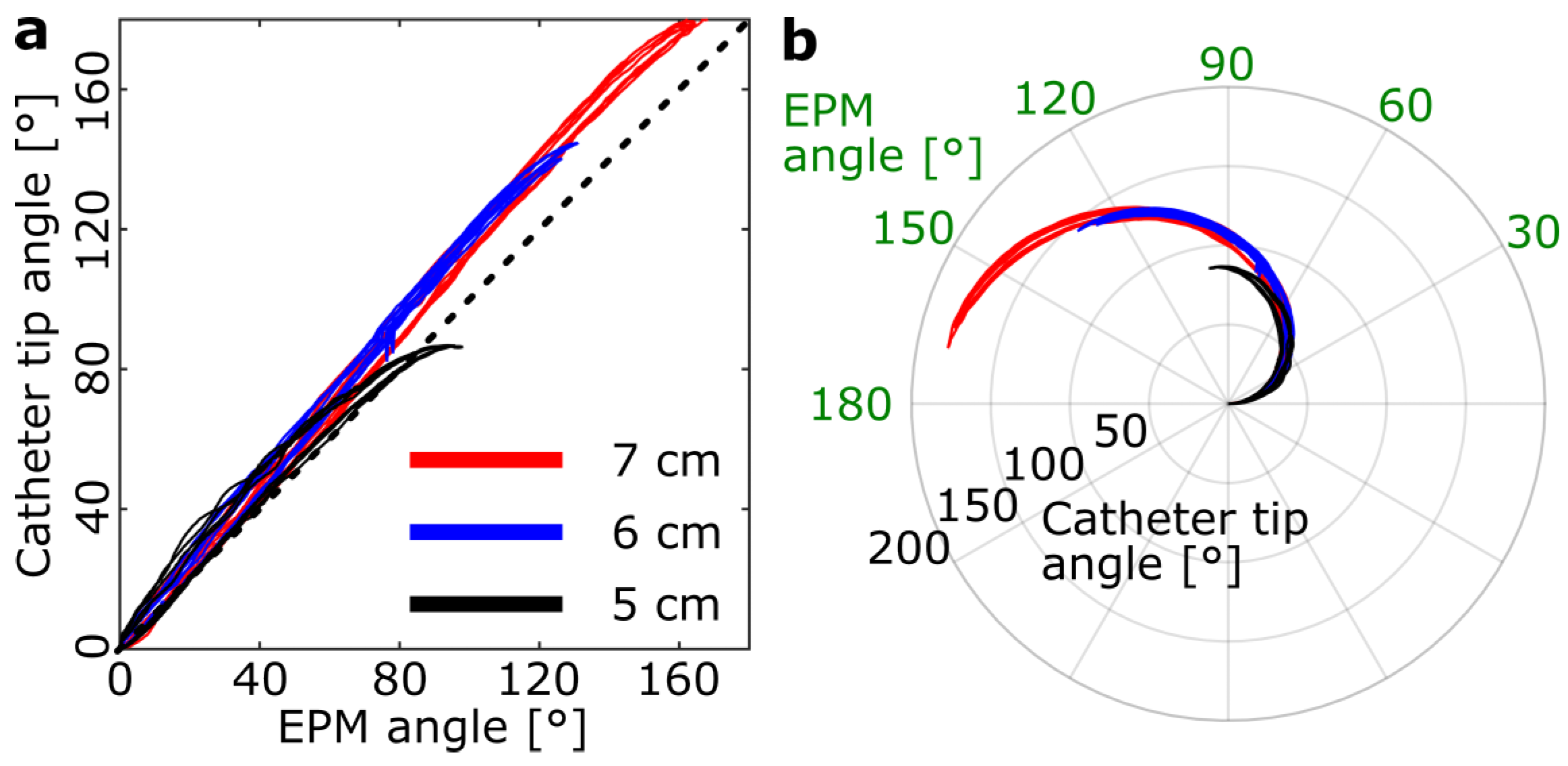
4.2. Bending Hysteresis
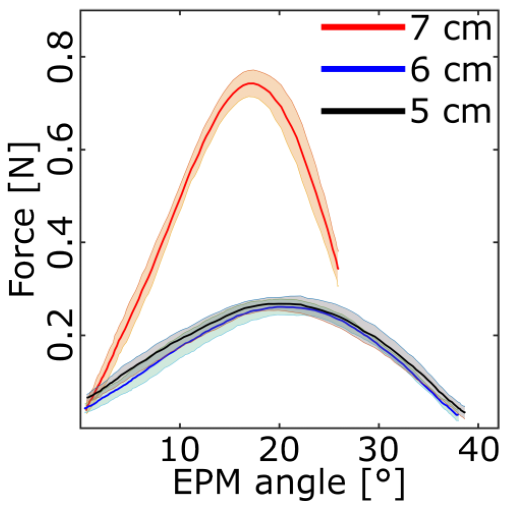
The bending response, i.e., the tip angle of the magnetic catheter vs. the EPM angle was recorded for different free lengths of the magnetic catheter (7 cm, 6 cm, and 5 cm) while maintaining a 15 cm distance of the clamped part of the magnetic catheter from the magnet. Depending on the target anatomy, the magnetic catheter may be restrained in bending only a section of it. Therefore, recording the bending response for different free lengths is necessary. The EPM was manually moved in an arc until the magnetic catheter reached a maximum bending angle, at which point the EPM was brought back to the initial state with the magnetic catheter following it. The resulting response is shown in Figure 4. With decreasing free length of the magnetic catheter, not only does the magnetic catheter tip become further from the EPM, but the magnetic volume available to be actuated also becomes reduced as only a portion of the 7 cm magnetic catheter is not constrained and is allowed to bend under the EPM field. As a result, as the free length of the magnetic catheter decreases, so does the maximum bending angle that the magnetic catheter can reach as observed from the bending response. The magnetic catheter is able to reach a bending angle of 180 with a free length of 7 cm, 140 with a free length of 6 cm, and 90 with a free length of 5 cm. The five repetitions for each free length almost overlap with each other which shows the good repeatability of the bending response of the magnetic catheter. For each loop, hysteresis was calculated as the percentage ratio of the area between the forward curve and the backward curve with respect to the area under the forward curve. The mean hysteresis was calculated by taking a mean of the hysteresis observed for five repetitions and was found to be 5.74%, 5.37%, and 9.87% for 7 cm, 6 cm and 5 cm free lengths, respectively. One factor contributing to the hysteresis could be the movement of the FBG fiber inside the lumen. While the FBG fiber was attached to the distal end of the magnetic catheter, it could still change position and slide from side-to-side within the lumen. While this could affect the bending angle as measured by the fiber, the mean hysteresis observed is low and therefore this curve could still be used for planning controlled actuation of the magnetic catheter without the need for any hysteresis compensation.

4.3. Bending Forces

To measure the bending forces of the magnetic catheter, the F/T sensor was fixed just above the tip of the magnetic catheter such that it constraints movement and the magnetic catheter will apply a force on it while trying to follow the EPM. The EPM angle was increased until a continuous decrease in maximum bending force was observed and then the angle was brought back to zero. This process was repeated 5 times for each magnetic catheter free length. A moving average low pass filter (n = 10) was applied to the resulting data to filter out the noise, and plotted in Figure 5. While the maximum bending force is the highest for the magnetic catheter free length of 7 cm ( 0.78 ± 0.02 N, forward loop), the values for the free lengths of 6 cm ( 0.27 ± 0.01 N, forward loop) and 5 cm ( 0.29 ± 0.02 N, forward loop) are similar. The EPM angle at which the maximum bending force is exhibited by the magnetic catheter is the lowest for the free length of 7 cm ( 17.42 ± 0 . 55 , forward loop), while the values for the free lengths of 6 cm ( 20.84 ± 3 . 10 , forward loop) and 5 cm ( 21.11 ± 2 . 37 , forward loop) are similar. The maximum bending force applied by the catheter arose for the 7 cm free length case. The strength of the magnetic interactions also depends on the volume of the magnetic material available, and, out of the three free lengths, it is the highest for 7 cm free length case. A longer length also brings the distal tip of the magnetic catheter closer to the EPM where the magnetic fields and gradients are stronger. The similarity observed between the 5 cm and 6 cm free length cases could be due to the non-uniformity of the magnetic catheter tip along its length resulting from manufacturing defects.

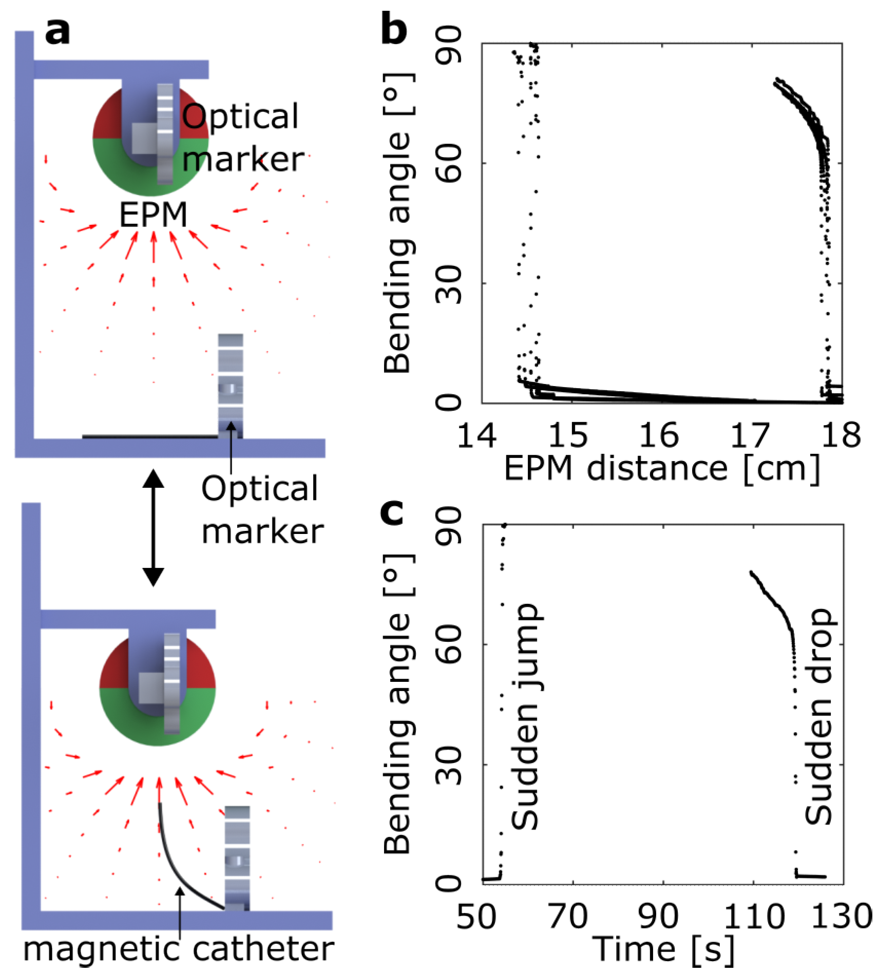
4.4. Dynamic Response

A magnetic catheter with a slow response time would induce a latency between the control signal given to it and the bending induced in it. The experimental setup to study the dynamic response of the magnetic catheter tip is shown in Figure 6a. The magnetic catheter was clamped on a horizontal surface such that the entire magnetic tip was free to move and an EPM was mounted above it on a vertical rail so that it could be moved up and down (in a manual fashion). The reconstructed shape of the magnetic catheter was overlayed on images captured using an optical camera (Prosilica®). The EPM was brought closer to the magnetic catheter as slow as manually possible (approximately 3 cm/min) and the bending angle as observed from FBG was plotted against the EPM distance as observed from the optical markers to generate a hysteresis curve, an example of which is shown in Figure 6b. As the EPM is brought closer to the magnetic catheter, it is found that the bending angle does not increase considerably until it reaches a point where the jump is sudden from near 0 to near 90 . This jump occurs when the distance between the EPM and the magnetic catheter is approximately 15 cm in this setting.
This behavior can be understood when considering the distribution of magnetic fields and gradients around the EPM. As explained in Section 3.1, the magnetic field applies a torque on the magnetic catheter to align it with itself, and the magnetic field gradient pulls it towards the EPM. When the magnetic catheter is lying flat on a surface below the EPM, the fields are not strong enough to bend it. Once the EPM is brought closer, the catheter starts bending towards the EPM and starts getting into the region of higher fields and higher gradients. Both of these further help the catheter to bend more which takes it to the region of even higher fields and gradients. Therefore, this acts like a multiplier effect and the process stops when the catheter has reached its maximum bending angle which is 90 for this setup. Since the magnetic catheter gathers some momentum due to the sudden jump and has limited damping, it fluctuates before settling at its final bending angle.
After reaching the maximum bending angle of the magnetic catheter, when the EPM is moved away, the reduction in bending angle is less sudden. That is because the magnetic catheter now is much closer to the EPM. Even as the EPM is moved away, the magnetic catheter still is relatively close to it resulting in a gradual decrease in the bending angle. When the fields and gradients are not strong enough, the magnetic catheter starts falling down. As this happens, the magnetic catheter reaches regions with lower and lower fields and gradients, until they are not strong enough to overcome gravity and therefore the magnetic catheter drops to 0 . During these movements, it is possible that the FBG fiber in the magnetic catheter changes its relative position which could result in it sensing a non-zero bending angle even when the magnetic catheter has dropped onto a flat surface. Nonetheless, the camera confirms that the magnetic catheter has gone back to a 0 bending angle. Data points when the magnetic catheter is bent by 90 are missing as at this state the bending is almost exclusively at the anchor point of the catheter. The single FBG grating at that position is not designed to handle such a large bending and therefore gives an error message and that data point is skipped. Nonetheless, the bent state of the magnetic catheter can be confirmed from the camera images. The sampling frequency of the experiments was 30 Hz, which was the maximum we could have because of hardware constraints. Having a higher sampling frequency could help us in having more data points during the sudden jump and drop and, therefore, better resolve them. The magnetic catheter jumps from near 0 to near 90 in <200 ms which confirms a good dynamic response of the developed magnetic catheter.

5. Conclusions

The fabrication of a custom soft hollow catheter tip based on extrusion is demonstrated. The procedure reported is beneficial as it does not require the use of any mold during the fabrication thereby simplifying the process. By choosing an appropriate nozzle through which extrusion takes place, different sizes of the magnetic catheter can be produced. The fabricated magnetic catheter can be attached to catheters to impart steering capabilities to them using remote magnetic fields. Here, we demonstrated the steering of the magnetic catheter using an EPM that is strong enough to manipulate the magnetic catheter but lightweight enough to be robot-mounted. Having a small EPM like the one reported here can be advantageous as having bigger magnets may require the future surgical rooms to be well isolated like Magnetic Resonance Imaging (MRI) rooms. Unlike this, robot-mounted magnets can be integrated into the current surgical rooms by redesigning the tools to be non-magnetic. The magnetic field around the EPM was modeled along with the bending of the magnetic catheter in it when the EPM is moved along an arc around the catheter. Despite the assumptions made in the modeling of the magnetic catheter bending, good predictions of the bending angles (root mean square error (RMSE) = 5 . 0 ) could be made. The distance of the EPM was kept constant at 15 cm from the catheter as it is an anatomically relevant distance when targeting endovascular applications. The bending of the magnetic catheter was also extensively characterized experimentally in terms of its hysteresis, bending force, and dynamic response. It was found that the magnetic catheter tip angle vs. EPM angle curve is repeatable with minimal hysteresis. Based on the mm-scale required accuracy for target applications, like stent graft placement [29], hysteresis compensation is not needed for the bending angle curve because of the low hysteresis. For further accuracy, localization sensors like FBG and EM may be used for closed-loop control.
Further, the maximum tip angle achieved was 180 in case of 7 cm free length and it reduced as the free length decreased. Depending on spatial constraints of the target anatomy, a corresponding free length of the magnetic catheter can be selected to predict its bending response. The maximum bending force of 0.8 N applied by the catheter was with 7 cm free length and it decreased with decreasing free lengths. The sudden jump observed in the bending angle of the magnetic catheter when the EPM was brought closer to it indicate a good dynamic response which is crucial for its safe and controlled steering. However, it also shows that a linear motion of the EPM is not ideal for control of the magnetic catheter and therefore an arc motion is needed. Based on these characterizations, a control strategy for the catheterization of coronary arteries could be developed in the future. A robotic arm mounted EPM could be used to guide and orient the magnetic tip while the magnetic catheter is being driven by a catheter driver. Shape reconstruction and localization techniques using FBG and EM sensors could help in the closed-loop control.

Author Contributions

Conceptualization, M.H.D.A., X.T.H., M.O., G.B., V.I., E.V.P. and A.M.; methodology, M.H.D.A., X.T.H., M.O., G.B., V.I., E.V.P. and A.M.; software, M.H.D.A. and X.T.H.; validation, M.H.D.A., X.T.H. and M.O.; formal analysis, M.H.D.A. and X.T.H.; investigation, M.H.D.A.; resources, M.O., G.B., V.I., E.V.P. and A.M.; data curation, M.H.D.A. and X.T.H.; writing—original draft preparation, M.H.D.A.; writing—review and editing, M.H.D.A., X.T.H., M.O., G.B., V.I., E.V.P. and A.M.; visualization, M.H.D.A.; supervision, M.O., G.B., V.I., E.V.P. and A.M.; project administration, E.V.P. and A.M.; funding acquisition, E.V.P. and A.M. All authors have read and agreed to the published version of the manuscript.

Funding

This work was supported by the ATLAS project. This project has received funding from the European Union’s Horizon 2020 research and innovation programme under the Marie Skłodowska-Curie grant agreement No 813782.

Data Availability Statement

The data that support the findings of this study are available from the corresponding author upon reasonable request.

Acknowledgments

The authors would like to thank Ayoob Davoodi, Ruixuan Li, and Omar Al-Ahmad for their help with the EPM manipulation, the optical tracking system, and the FBG sensor, respectively.

Conflicts of Interest

The authors declare no conflict of interest. The funders had no role in the design of the study; in the collection, analyses, or interpretation of data; in the writing of the manuscript; or in the decision to publish the results.

Abbreviations

The following abbreviations are used in this manuscript:
3DThree Dimensional
DoFsDegrees of Freedom
EMElectro-Magnetic
EPMExternal Permanent Magnet
FBGFiber Bragg Grating
F/TForce/Torque
IVUSIntravascular Ultrasound
MCmagnetic catheter
MRIMagnetic Resonance Imaging
NdFeBNeodymium Iron Boron
PAMPneumatic Artificial Muscle
RMSEroot mean square error
ROSRobotic Operative System
UVUltra-violet

References

  1. Hoffman, S.N.; TenBrook, J.A.; Wolf, M.P.; Wong, J.B.; Pauker, S.G.; Salem, D.N. A meta-analysis of randomized controlled trials comparing coronary artery bypass graft with percutaneous transluminal coronary angioplasty: One- to eight-year outcomes. J. Am. Coll. Cardiol. 2003, 41, 1293–1304. [Google Scholar] [CrossRef] [PubMed]
  2. Guez, D.; Hansberry, D.R.; Gonsalves, C.F.; Eschelman, D.J.; Parker, L.; Rao, V.M.; Levin, D.C. Recent Trends in Endovascular and Surgical Treatment of Peripheral Arterial Disease in the Medicare Population. Am. J. Roentgenol. 2020, 214, 962–966. [Google Scholar] [CrossRef] [PubMed]
  3. O’Laughlin, M.P.; Perry, S.B.; Lock, J.E.; Mullins, C.E. Use of endovascular stents in congenital heart disease. Circulation 1991, 83, 1923–1939. [Google Scholar] [CrossRef] [PubMed]
  4. Liu, P.; Ren, S.; Yang, Y.; Liu, J.; Ye, Z.; Lin, F. Intravenous Catheter-Guided Laser Ablation: A Novel Alternative for Branch Varicose Veins. Int. Surg. 2011, 96, 331–336. [Google Scholar] [CrossRef] [PubMed]
  5. Farola Barata, B.; Tran, P.T.; Borghesan, G.; McCutcheon, K.; Dall’Alba, D.; Fiorini, P.; Vander Sloten, J.; Poorten, E.V. IVUS-Based Local Vessel Estimation for Robotic Intravascular Navigation. IEEE Robot. Autom. Lett. 2021, 6, 8102–8109. [Google Scholar] [CrossRef]
  6. Gunduz, S.; Albadawi, H.; Oklu, R. Robotic Devices for Minimally Invasive Endovascular Interventions: A New Dawn for Interventional Radiology. Adv. Intell. Syst. 2021, 3, 2000181. [Google Scholar] [CrossRef]
  7. Ali, A.; Plettenburg, D.H.; Breedveld, P. Steerable Catheters in Cardiology: Classifying Steerability and Assessing Future Challenges. IEEE Trans. Biomed. Eng. 2016, 63, 679–693. [Google Scholar] [CrossRef]
  8. Agilis Nxt Steerable Introducer. Available online: https://www.cardiovascular.abbott/us/en/hcp/products/electrophysiology/access-introducers/agilis-nxt/about.html (accessed on 15 October 2022).
  9. Uncovering Treatment Pathways with Robotic Assisted Procedures. Available online: https://www.jnjmedtech.com/en-US/product-family/monarch (accessed on 15 October 2022).
  10. Dario, P.; Valleggi, R.; Pardini, M.; Sabatini, A. A miniature device for medical intracavitary intervention. In Proceedings of the [1991] Proceedings, IEEE Micro Electro Mechanical Systems, Nara, Japan, 30 January–2 February 1991; pp. 171–175. [Google Scholar]
  11. Kalita, B.; Leonessa, A.; Dwivedy, S.K. A Review on the Development of Pneumatic Artificial Muscle Actuators: Force Model and Application. Actuators 2022, 11, 288. [Google Scholar] [CrossRef]
  12. Gopesh, T.; Wen, J.H.; Santiago-Dieppa, D.; Yan, B.; Pannell, J.S.; Khalessi, A.; Norbash, A.; Friend, J. Soft robotic steerable microcatheter for the endovascular treatment of cerebral disorders. Sci. Robot. 2021, 6, eabf0601. [Google Scholar] [CrossRef]
  13. Webster, R.J.; Romano, J.M.; Cowan, N.J. Mechanics of Precurved-Tube Continuum Robots. IEEE Trans. Robot. 2009, 25, 67–78. [Google Scholar] [CrossRef]
  14. Hu, X.; Chen, A.; Luo, Y.; Zhang, C.; Zhang, E. Steerable catheters for minimally invasive surgery: A review and future directions. Comput. Assist. Surg. 2018, 23, 21–41. [Google Scholar] [CrossRef] [PubMed]
  15. Xu, T.; Yu, J.; Yan, X.; Choi, H.; Zhang, L. Magnetic Actuation Based Motion Control for Microrobots: An Overview. Micromachines 2015, 6, 1346–1364. [Google Scholar] [CrossRef]
  16. El-Atab, N.; Mishra, R.B.; Al-Modaf, F.; Joharji, L.; Alsharif, A.A.; Alamoudi, H.; Diaz, M.; Qaiser, N.; Hussain, M.M. Soft Actuators for Soft Robotic Applications: A Review. Adv. Intell. Syst. 2020, 2, 2000128. [Google Scholar] [CrossRef]
  17. Choi, M.S.; Oh, Y.S.; Jang, S.W.; Kim, J.H.; Shin, W.S.; Youn, H.J.; Jung, W.S.; Lee, M.Y.; Seong, K.B. Comparison of Magnetic Navigation System and Conventional Method in Catheter Ablation of Atrial Fibrillation: Is Magnetic Navigation System Is More Effective and Safer Than Conventional Method? Korean Circ. J. 2011, 41, 248–252. [Google Scholar] [CrossRef] [PubMed]
  18. Schenck, J.F. Safety of Strong, Static Magnetic Fields. J. Magn. Reson. Imaging 2000, 12, 2–19. [Google Scholar] [CrossRef] [PubMed]
  19. Tillander, H. Magnetic Guidance of a Catheter with Articulated Steel Tip. Acta Radiol. 1951, 35, 62–64. [Google Scholar] [CrossRef] [PubMed]
  20. Faddis, M.N.; Blume, W.; Finney, J.; Hall, A.; Rauch, J.; Sell, J.; Bae, K.T.; Talcott, M.; Lindsay, B. Novel, Magnetically Guided Catheter for Endocardial Mapping and Radiofrequency Catheter Ablation. Circulation 2002, 106, 2980–2985. [Google Scholar] [CrossRef]
  21. Pittiglio, G.; Lloyd, P.; da Veiga, T.; Onaizah, O.; Pompili, C.; Chandler, J.H.; Valdastri, P. Patient-Specific Magnetic Catheters for Atraumatic Autonomous Endoscopy. Soft Robot. 2022, 9, 1120–1133. [Google Scholar] [CrossRef]
  22. U.S. Food and Drug Administration (FDA). Class 2 Medical Device Recalls: Cronus Endovascular Guidewires (510(K) Number: K021363, FDA, 2004). Available online: https://www.accessdata.fda.gov/scripts/cdrh/cfdocs/cfRES/res.cfm?start_search=1&knumber=K021363 (accessed on 16 October 2022).
  23. Kim, Y.; Parada, G.A.; Liu, S.; Zhao, X. Ferromagnetic soft continuum robots. Sci. Robot. 2019, 4, eaax7329. [Google Scholar] [CrossRef]
  24. Cianchetti, M.; Laschi, C.; Menciassi, A.; Dario, P. Biomedical applications of soft robotics. Nat. Rev. Mater. 2018, 3, 143–153. [Google Scholar] [CrossRef]
  25. Ansari, M.H.D.; Iacovacci, V.; Pane, S.; Ourak, M.; Borghesan, G.; Tamadon, I.; Vander Poorten, E.; Menciassi, A. 3D Printing of Small-Scale Soft Robots with Programmable Magnetization. Adv. Funct. Mater. 2023, 33, 2211918. [Google Scholar] [CrossRef]
  26. Petruska, A.J.; Abbott, J.J. Optimal Permanent-Magnet Geometries for Dipole Field Approximation. IEEE Trans. Magn. 2013, 49, 811–819. [Google Scholar] [CrossRef]
  27. Ha, X.T.; Ourak, M.; Al-Ahmad, O.; Wu, D.; Borghesan, G.; Menciassi, A.; Vander Poorten, E. Robust Catheter Tracking by Fusing Electromagnetic Tracking, Fiber Bragg Grating and Sparse Fluoroscopic Images. IEEE Sens. J. 2021, 21, 23422–23434. [Google Scholar] [CrossRef]
  28. Quigley, M.; Conley, K.; Gerkey, B.; Faust, J.; Foote, T.; Leibs, J.; Wheeler, R.; Ng, A.Y. ROS: An open-source Robot Operating System. In Proceedings of the ICRA Workshop on Open Source Software, Kobe, Japan, 12–17 May 2009; Volume 3, p. 5. [Google Scholar]
  29. Kaladji, A.; Dumenil, A.; Mahé, G.; Castro, M.; Cardon, A.; Lucas, A.; Haigron, P. Safety and Accuracy of Endovascular Aneurysm Repair Without Pre-operative and Intra-operative Contrast Agent. Eur. J. Vasc. Endovasc. Surg. 2015, 49, 255–261. [Google Scholar] [CrossRef]
Figure 1. (a) Schematicof the extrusion based fabrication method used and (b) a section view of the nozzle used for extrusion showing the annular space through which the material is extruded. (c) Fabricated magnetic catheter tip attached to a medical catheter (Scale bar: 10 cm). The attachment point between the magnetic catheter tip and the medical catheter is raised from the surface below which makes the magnetic catheter tip cast a shadow on the surface. (d) A closeup of a part of the fabricated magnetic catheter tip (Scale bar: 2 cm).
Actuators 12 00409 g001
Figure 2. (a) The forces and torque acting on each segment of the modeled magnetic catheter. The deflection due to each of the components is calculated and added to give δ t o t a l , i . Assuming the segment length remains the same, the angle of deflection θ t o t a l , i is then calculated after which the updated shape of the segment is approximated as a straight line with the updated angle. (b) The magnetic catheter at three different angles of the EPM. Reconstructed shape from the FBG fiber described in Section 4.1 is superimposed in red and the corresponding modeling result is drawn in blue (Scale bar: 1 cm).
Actuators 12 00409 g002
Figure 3. (a) The top view of the characterization test system where the EPM and magnetic catheter which carries within its lumen a FBG fiber can be seen. When measuring the bending forces, the F/T sensor was placed as shown. The black arrows at the EPM and at the magnetic catheter represent their magnetization directions. (b) From the side view the motion of the EPM in an arc can be seen which also bends the catheter along with it. A representative image of a bent catheter when the EPM is moved in an arc is also shown. When the F/T sensor is placed, it constraints the movement of the magnetic catheter which will apply a force on it when trying to follow the EPM. The free length of the magnetic catheter which could be varied can also be seen.
Actuators 12 00409 g003
Figure 4. (a) Cartesian plot and (b) polar plot of magnetic catheter tip bending angle measured by FBG in response to varying EPM angle measured by optical tracking system for different catheter free lengths (7 cm, 6 cm, and 5 cm). The dotted line in (a) represents the 45 line y = x . For each free length, 5 repetitions are plotted. The 5 lines generally overlap showing good repeatability. For a view on the actual shapes of the magnetic catheter tip, please refer to Figure 2.
Actuators 12 00409 g004
Figure 5. Bending force measurement of the magnetic catheter. The bending force vs. EPM angle for the different free lengths of the magnetic catheter is plotted. The line plot represents the mean bending force, and the shaded regions represent their respective standard deviations (Sample size: 10). The catheter is constrained to move using a F/T sensor throughout these measurements.
Actuators 12 00409 g005
Figure 6. Investigation of the dynamic behavior of the magnetic catheter. (a) The placement and movement of the EPM with respect to magnetic catheter. The strength of the magnetic field is qualitatively shown by red arrows. (b) The resulting bending angle of the magnetic catheter vs. the distance of EPM from the magnetic catheter for 7 cm free length (Sample size: 5). (c) A sample plot showing the bending angle against time showing the sudden jump and the sudden drop of the magnetic catheter.
Actuators 12 00409 g006
Disclaimer/Publisher’s Note: The statements, opinions and data contained in all publications are solely those of the individual author(s) and contributor(s) and not of MDPI and/or the editor(s). MDPI and/or the editor(s) disclaim responsibility for any injury to people or property resulting from any ideas, methods, instructions or products referred to in the content.

