Article

Microforce Sensing and Flexible Assembly Method for Key Parts of ICF Microtargets

Research Institute of Advanced Manufacturing Technology, Soochow University, Suzhou 215000, China
*
Author to whom correspondence should be addressed.
Actuators 2023, 12(1), 1; https://doi.org/10.3390/act12010001
Submission received: 13 November 2022 / Revised: 14 December 2022 / Accepted: 15 December 2022 / Published: 20 December 2022

Abstract

:
Microassembly is one of the key techniques in various advanced industrial applications. Meanwhile, high success rates for axial hole assembly of thin-walled deep-cavity-type items remain a challenging issue. Hence, the flexible assembly approach of thin-walled deep-cavity parts is investigated in this study using the assembly of the key components, the microtarget component TMP (thermomechanical package) and the hohlraum in ICF (inertial confinement fusion) research, as examples. A clamping force-assembly force mapping model based on multisource microforce sensors was developed to overcome the incapacity of microscopic vision to properly identify the condition of components after contact. The ICF microtarget flexible assembly system, which integrates multisource microforce sensing and a six degrees of freedom micromotion sliding table, is presented to address the constraint that the standard microassembly approach is difficult to operate once the parts contact. This method can detect contact force down to the mN level, modify deviation of the component posture efficiently, and achieve nondestructive ICF microtarget assembly at the end.

1. Introduction

Microtarget parts, which are crucial for laser inertial confinement fusion, are often made up of several cross-scale, uneven, and deformation-prone small pieces. Traditional macroscopic assembly methods and control strategies are no longer appropriate because of the scale effect, surface effect, and tunneling effect demonstrated by microdevices during assembly [1]. As a result, a customized microassembly procedure for microtarget parts becomes an effective way to assure a high success rate for nuclear fusion ignition.
Precision assembly techniques for ICF microtargets have been developed rapidly over the decades [2,3,4]. For example, a final assembly machine (FAM) was designed and fabricated at Lawrence Livermore National Laboratory, USA. This device combines microforce sensing and optically assisted measurement systems [5] to operate millimeter-scale target components with submicron precision. General Atomics Technologies has developed a semiautomatic assembly system to assemble high-volume microtargets for laser inertial confinement fusion [6]. In China, the Laser Fusion Research Center of the Chinese Academy of Engineering Physics has developed an automatic assembly experimental system for microtarget assembly using microscopic image detection [7]. It can be used for verifying the assembly tests of various ICF microtarget parts. Traditional microtarget assembly research, on the other hand, has focused on semiautomatic assembly. With the advancement of controlled fusion technology, fulfilling high-precision assembly requirements for diversified microtarget devices is becoming increasingly difficult. Because the microtarget assembly system is usually a rigid assembly system when building a part’s axial hole, microscopic vision is frequently utilized for rough positioning of the part posture first while ignoring the part’s control after contact. At this moment, a minor misalignment of the part might cause assembly failure and even harm the part [8].
As a critical component of controlled fusion ignition, microtarget assembly is separated into two parts: axial hole assembly and spherical film assembly. The parts in axial hole assembly are primarily thin-walled deep-cylinder parts (such as aluminum sleeves, hohlraums, etc.) that may deform easily due to coaxiality inaccuracy in the contact condition. Researchers have combined precision motion controllers and microforce sensors to solve this challenge [9,10]. Their assembly inspection, on the other hand, focuses on alignment issues that arise during the part’s precontact time, with little attention paid to the postcontact condition. Park et al. designed a new RCC device based on the telecenter flexible wrist (remote center compliance, RCC) [11] presented by MIT. The device has a deformation measurement system that can effectively improve shaft-hole assembly efficiency with a robot assembly strategy [12], but its working mechanism is complex. Jakovljevic et al. [13] proposed a fuzzy inference mechanism to identify the contact state of the shaft-hole, which can predict the contact state of the shaft-hole and successfully avoid the problem of assembly shaft-hole jamming with a robust assembly environment adaptability. On the other hand, its control algorithm is complicated, and the coupling problem of force and position control cannot be handled fundamentally. Aiming at the problem that it is difficult to control thin-walled deep-cavity-type parts in the link after contact during shaft-hole assembly, this paper takes the assembly of TMP-hohlraum components in ICF microtargets as the research object and establishes a mechanical model for the relationship between gripper clamping force and part assembly force. In this paper, a flexible assembly platform with a combination of master and slave is designed, research on the control method of overfill assembly based on microforce sensing and flexible control is carried out, and the nondestructive assembly of a TMP-hohlraum component is completed.

2. Structure of Half-Hohlraum Component

Half-hohlraum assembly is conducted by a TMP component and hohlraum transition, as shown in Figure 1. In the assembly, the sleeve is fixed on the silicon arm through interference fitting and assembly is finished with the hohlraum. The sleeve is a thin-walled cylinder-like structure made of aluminum; the wall thickness is 0.2 mm, and the diameter is 5 mm. The hohlraum is a thin-walled deep-cylinder-like structure made of gold; the wall thickness is about 0.1 mm, and the diameter is about 2.5~3 mm, which makes the wall vulnerable to deformation. At present, the assembly of TMP components and hohlraums is mainly done by microscopic vision after the alignment of the position is set. However, the accuracy of visual inspection is restricted. Inaccuracy is likely to cause cavity posture deviation after contact with the sleeve, and a larger assembly force may even cause the cavity to create uneven deformation, resulting in part damage. A flexible assembly platform was developed to tackle this challenge. The relative posture of the pieces is changed using kinematic analysis of the micromotion platform and mechanical modeling of the end gripper to achieve nondestructive assembly of the TMP components and hohlraums.

3. Design and Analysis of the Supply Assembly System

3.1. Design of the Part Gripper

3.1.1. Silion Arm Adsorber

The assembly of the sleeve to the hohlraum usually follows the assembly of the TMP component. During the assembly process, the sleeve is fastened to one side of the silicon arm and gripped by a silicon arm adsorber. A silicon arm adsorber is constructed, as illustrated in the bottom left of Figure 2, for the adsorption and fixing of the TMP component’s thin and light silicon arm, which is difficult to retain. The silicon arm is positioned using the positioning pin. The adsorption slot is utilized to create adsorption force in order to secure the TMP component to the silicon arm adsorber’s lower surface. The sensor used in the silicon arm adsorber is the Nano17 6D (six-dimensional) force/moment sensor, which measures the 3D (three-dimensional) spatial force and 3D spatial moment at the end position of the adsorber. The lower end of the silicon arm adsorber is used to adsorb and hold the TMP component. Its upper end is connected to the Nano17 6D force/moment sensor.
The Nano17 microrange 6D force sensor is used in the 6D force/moment sensor. The sensor has an mN force detection accuracy, a 3 mN force resolution, and can withstand a ±12 N force in the x- and y-axis directions as well as a ±17 N force in the z-axis. The technical specifications of the 6D force/torque sensor are listed in Table 1.

3.1.2. Flexible Support Platform

The flexible support stage, as shown on the right side of Figure 2, is designed to ensure the deflection accuracy required in the components’ assembly process. The flexible support platform is designed around the universal joint principle and consists primarily of an upper connecting block, cross shaft, lower connecting block, force sensor, and sensitive beam. Both force sensors A and B are connected to the cross shaft, and sensitive beams A and B are connected to force sensor A and force sensor B, respectively. Table 2 shows the technical details of the cantilever beam force sensor used for the flexible support platform.

3.1.3. Design of Six DoF MicroMotion Platform

A six DoF (six degrees of freedom) micromotion stage is intended to suit the needs of the positioning adjustment of the TMP components during assembly, as shown on the left side of Figure 2. The major parameters of the six DoF micromotion stage are listed in Table 3.

3.2. Mechanical Modeling Analysis

In the fundamental analysis, in order to simplify the problem, the following assumptions are made:
  • Assume that the assembly object is a rigid body (ignoring deformation).
  • Assume that the assembly process is a quasistatic equilibrium process, ignoring the effect of inertial forces generated by the acceleration of the assembly object.
  • Assume that the dynamic and static friction coefficients during the assembly process are equal.

3.2.1. Mechanical Modeling Analysis of the Adsorber

The force perception is expressed as bore contact when the silicon arm adsorber is adsorbing the TMP component for assembly operations. When the radial force is applied, the inner wall of the sleeve makes direct contact with the hohlraum, pointing along the axis to the outer circle.
A 3D model section view of the TMP component adsorbed by the silicon arm adsorber is shown in Figure 3. The sensor coordinate system of the Nano17 6D force sensor is established as the right-angle coordinate system O0-x0y0z0 with the origin O0 being the center of Nano17. To build the part coordinate system O1-x1y1z1, the origin O1 is the center of the upper surface of the sleeve, and the z1 axis is the center axis of the sleeve. The sensor coordinate system’s O0-x0z0 plane is coplanar with the part coordinate system’s O1-x1z1 plane due to the part’s symmetry. Let the deviation of axis z0 from axis z1 in the positive direction along axis x0 be lx, the deviation of axis x0 from axis x1 in the positive direction along axis z0 be lz, and the inner diameter of the sleeve be r. When the TMP component is in force contact with the assembly object, let the forces and moments measured by the 6D force sensor be Fx, Fy, Fz, Mx, My, Mz, the coordinate values of the contact point of the TMP component in the O0-x0y0z0 coordinate system be (x, y, z), the axial force generated at the contact point be Fa1, and the radial force generated at the contact point be Fr1. The O1-x1 axis angle is θ, and the distance from the contact point to the O1-x1y1 plane is h.
The coordinates (x, y, z) of the geometrically related contact points satisfy
{ x = l x + r cos θ y = r sin θ z = l z + h
From the principles of mechanics, it is clear that the force, moment, and coordinate values of the contact point generated by the 6D force sensor satisfy the following relationship
{ F x = F r 1 cos θ F y = F r 1 sin θ F z = F a 1 M x = F a 1 y F r 1 sin θ z M y = F a 1 x + F r 1 cos θ z M z = F r 1 sin θ x F r 1 cos θ y
After calculation, it is obtained that θ satisfies
θ = { π 2 F x = 0 , F y > 0 3 π 2 F x = 0 , F y < 0 a c c tan F y F x F x > 0 π + arctan F y F x F x < 0
Organizing Equation (2) yields
{ M x = F z y F y z M y = F z x + F x z M z = F y x F x y
The joint Formulas (1), (3) and (4) can be obtained
h = { M y F z l x F z r cos θ F x l z F x 0 M x F z r sin θ F y l F x = 0

3.2.2. Mechanical Modeling Analysis of the Platform

As in Figure 4, the right-angle coordinate system O0x0y0z0 is established with the cross-axis center as the origin O0, respectively, over the two axes of the cross-axis. The upper connecting block is deflected around axis y concerning the cross-axis, and the lower connecting block is deflected around axis x0 concerning the cross-axis. In the figure, point P is the vertex carrying the part to be assembled, point A is the contact point between force sensor A and the upper connecting block, point B is the contact point between force sensor B and the lower connecting block, the distance between point P and the origin O0 is L, the distance between point A and the origin O0 is lA, and the distance between point B and the origin O0 is lB.
Force F can be divided into force Fx and force Fy along the x0 and y0 axes in the O0x0y0 plane when point P is subjected to force F in the O0x0y0 plane. The force Fy is applied to the upper connecting block, which is gently deflected around the x0 axis in the direction of force Fy before being forced to compress the pressure sensor B. At this time, force sensor B generates the interaction force FSy on the upper connecting block.
Defining the slight deflection along the direction of the partial force Fx when the point P is acted upon by the force F as ∆xA and the slight deflection along the direction of the partial force Fy when the point P is acted upon by the force F as ∆xB, the overall deflection ∆x produced by the point P is
Δ x = Δ x A 2 + Δ x B 2
At this point, the resulting angular deflection α is
α = arctan Δ x L = arctan Δ x A 2 + Δ x B 2 L
The forces and displacements at the gripper’s end are estimated using the top plane of the flexible support platform’s calibration data. Figure 5 depicts the force and displacement analysis for the flexible support platform’s deflection around the y-axis.
As in Figure 5a, according to the geometric principle, there is
M E l E = M P l p
Therefore, the displacement relationship between the clamping end and the calibration plane satisfies
M E = M P × l E l P
As in Figure 5b,c, according to the mechanics, there are
{ F S × l S = F P × l P F S × l s = F E × l E
Therefore, the force relationship between the clamping end and the calibration plane satisfies
F E = F P × l P l E
Similarly, the deflection of the flexible support platform around the direction of the x-axis also satisfies the state analysis of force and displacement as above.

3.2.3. Kinematic Analysis of Micromotion Platforms

Control techniques are investigated in assembly tasks based on the state of the part at the gripper’s end. To determine the relative location of the parts at the gripper’s end, a kinematic analysis of the six DoF micromotion stage and the gripper module is required.
The six DoF micromotion stage is a robotic arm made up of a succession of links and joints that are arranged in a specified order. The z-axis of each coordinate system corresponds to the direction of each joint degree of freedom, as shown in Figure 6. Each reference coordinate system also has a transformation matrix that allows them to be translated into one another.
The transformation matrix of the reference coordinate system between adjacent joints can be written as ii−1T = Ai according to the Denavit-Hartenberg (D-H) [14] approach to robot kinematic modeling, i.e.,
T i i 1 = [ c θ i s θ i 0 a i 1 s θ i c α i 1 c θ i c α i 1 s α i 1 s α i 1 d i s θ i s α i 1 c θ i c α i 1 c α i 1 c α i 1 d i 0 0 0 1 ]
where sin and cos are simplified to s and c, respectively, i is the serial number of the joint, αi is the rotation angle between two adjacent joints along the z-axis, θ is the rotation angle between joints along the z-axis, ai is the length of the link between two joints, and di is the distance between the z-axis perpendiculars between joints. Table 4 lists the corresponding parameters between the joints in the 6 DoF micromotion stage. d1, d2, and d3 are the sliding transformations of the corresponding joints.
By multiplying the obtained transformation matrix, the transformation matrix between the end of the six DoF microstage gripper and the base is obtained, which is the total transformation matrix
T 6 0 = T 1 0 T 2 1 T 3 2 T 4 3 T 5 4 T 6 5 = [ n x o x a x p x n y o y a y p y n z o z a z p z 0 0 0 1 ]
[nx ny nz]T, [ox oy oz]T, [ax ay az]T are the attitude coordinates of the gripper end; [px py pz]T is the position coordinate of the gripper end, respectively.
The positioning matrix at the end of the gripper was acquired using Matlab for matrix multiplication calculations, as given in Equation (13), and the specific values are derived as follows.
p x = a 1 + d 3 d 6 sin θ 4 sin θ 5 p y = d 2 d 6 cos θ 4 sin θ 5 p z = d 1 a 2 d 6 cos θ 5
The displacement matrix can be determined from the actual dimensions of the gripper after the six DoF micromotion stage is installed with the gripper
A H = [ 1 0 0 h 1 0 1 0 h 2 0 0 1 h 3 0 0 0 1 ]
Multiplying with the transformation matrix of the six DoF micromotion stage yields
T H 0 = A 1 A 2 A 3 A 4 A 5 A 6 A H
For the case of vertical assembly, in the initial state, θ4 = −90°, θ5 = −90°, θ6 = −90°, and when substituted into Equation (15), yields
{ p x 1 = a 1 + d 3 d 6 h 3 p y 1 = d 2 + h 1 p z 1 = d 1 a 2 d 4 h 2
The overall performance of the positional adjustment in the part assembly is that the posture adjustment is the first followed by the positional adjustment. In the part coordinate system OxHyHzH, the angular deviations β1 and β2 of the part along the xH and yH directions are obtained first. Then, the positional deviations e1, e2, and e3 along the xH, yH, and zH directions are obtained.
According to the posture transformation relationship, θ4 = −90° + β2, θ5 = −90° − β1, θ6 = −90°, which can be obtained by substituting into Equation (15).
{ p x 2 = a 1 + d 3 + h 1 sin β 2 ( d 6 + h 3 ) cos β 1 cos β 2 h 2 cos β 2 sin β 1 p y 2 = d 2 + h 1 cos β 2 + ( d 6 + h 3 ) cos β 1 sin β 2 + h 2 sin β 1 sin β 2 p z 2 = d 1 a 2 d 4 h 2 cos β 1 + ( d 6 + h 3 ) sin β 1
The joint Equations (16) and (17) can be obtained after the attitude adjustment, the position deviation in the Ox0y0z0 coordinate system satisfies
{ Δ x = h 1 sin β 2 + ( d 6 + h 3 ) cos β 1 cos β 2 + h 2 cos β 2 sin β 1 d 6 h 3 e 3 Δ y = h 1 cos β 2 ( d 6 + h 3 ) cos β 1 sin β 2 h 2 sin β 1 sin β 2 + h 1 + e 1 Δ z = h 2 cos β 1 ( d 6 + h 3 ) sin β 1 + h 2 e 2

4. Assembly Strategy for TMP-Hohlraum Component

For the assembly of ICF parts, the general assembly strategy is “visual guidance + force control”. Visual guidance” is used in the noncontact phase of the part, and “force control” is used in the contact phase of the part.

4.1. Visual Guidance in Assembly

As shown in the top right corner of Figure 2, the assembly of the TMP component and hohlraum is a typical axial hole assembly. When assembling, two horizontal CCD cameras are set in the horizontal direction to observe the position of the parts.
The silicon arm adsorber is fixed to the end of the six DoF stage during assembly. The TMP component can be adjusted by controlling the six DoF stage. The assembly of the TMP component and the hohlraum can be divided into two cases according to the contact status of the parts: the noncontact phase and the contact phase.
Visual guiding is utilized to alter the posture of the part during the noncontact phase. The TMP component-hohlraum posture adjustment condition is depicted schematically in Figure 7. First, as illustrated in Figure 7a, the TMP component and hohlraum are manually positioned to the observing field of view of two horizontal CCD cameras. The host computer’s posture measuring unit is then used to determine the TMP component and cavity’s posture status. Furthermore, the posture of the TMP component is initially modified based on the acquired posture information, and then the posture of the TMP component is altered. The TMP component’s position adjustment is coarse, as seen in Figure 7b. It is required to reserve the safety distance to avoid collision damage to the part caused by the attitude adjustment. The TMP component is then carefully adjusted until the part establishes force contact, as shown in Figure 7c, at which point visual guidance is complete. The flow chart for the TMP component-hohlraum position adjustment is shown in Figure 8.

4.2. Force Guidance in Assembly

During the contact phase of the part, force-aware control is used to complete the assembly. Figure 9 depicts a schematic diagram of the TMP component-hohlraum’s force-aware adjustment trajectory. The TMP component travels downward in the vertical direction when no forceful contact is detected in the horizontal direction or when the contact force is less than the safety threshold, and the contact force in the vertical direction is less than the safety threshold, as shown in Figure 9a. The downward motion of the TMP component along the vertical direction is stopped when the contact force is detected in the horizontal direction that is greater than the safety threshold. Furthermore, as illustrated in Figure 9b, the horizontal state’s position is altered based on force contact information until the force contact detected in the horizontal direction is less than the safety threshold. When force contact in the horizontal direction is less than the safety threshold and force contact in the vertical direction is more than the safety threshold, the assembly is complete. The flow chart of the TMP component-hohlraum force sense adjustment is shown in Figure 10.

5. Assembly Experiment

5.1. Performance Testing of Flexibly Support Platform

A rigid assembly platform was developed to assess the effect of the flexible support platform, as shown in Figure 11. All of the assembly settings were kept the same in the comparison experiment with the exception of the support platform, which was replaced with a rigid support platform. The radial contact force feedback threshold was set to 0.03 N, and the feed rate was set to 60 μm/s.
Figure 12 depicts the assembly’s force state when using a flexible and rigid support platform, respectively. When a rigid support platform was used for assembly versus a flexible support platform, the assembly force in the radial direction had several abrupt changes, as shown in Figure 12a,b. When using the flexible support platform, however, the radial assembly force curve was quite flat. When assembling using a rigid support platform against a flexible support platform, the change of force in the axial direction was lower, as shown in Figure 12c.
Based on the findings, it can be concluded that, when compared to rigid support stages, the use of flexible support stages for assembly can give a degree of suppleness in the components’ radial contact direction. This improves the smoothness of the assembly process by smoothing the radial contact during assembly.
In the assembly process, the distance between the rotating pivot point of the flexible support platform and the hohlraum parts was about 200 mm. When the deflection threshold of the parts held at the end of the flexible support platform was set at 100 μm, the following can be obtained by substituting into Equation (7):
α = arctan Δ x L = arctan 100 μ m 200 m m = 0.02864 °
Figure 13 is the calculation of the hohlraum deflection chart drawn according to the flexible platform fitting curve and the actual size of the gripper. According to the data in the chart, it can be judged that when the assembly depth was 1400 μm, the x-directional deflection produced by the end part of the flexible support platform was about 20 μm, and the y-directional deflection produced was about 60 μm. It can be calculated that the integrated radial deflection at this time was less than 100 μm, i.e., the gold cavity around the deflection produced by the flexible platform rotating pivot point was less than 0.03°. By calculating the deflection of the hohlraum, it was beneficial to control the force during the assembly process and optimize the control of the assembly process.

5.2. Assembly Experiment

The TMP component and the hohlraum were assembled using the same method as the vertical axis hole. During the assembling process, a force contact between the inner wall of the sleeve and the outer wall of the gold chamber was created. The succeeding experiments were built around the assembling of the TMP component and the hohlraum. Furthermore, because the hohlraum is a thin and delicate element, excessive force contact or an irrational method can easily lead to assembly failure. As a result, the TMP component and the hohlraum assembly must be tested.
Figure 14 shows the built TMP component and hohlraum assembly platform, including one six DoF micromotion stage, one flexible support stage, one silicon arm adsorber, one hohlraum gripper, and two CCD cameras. The Oxyz coordinate system is the coordinate system of the assembly system.

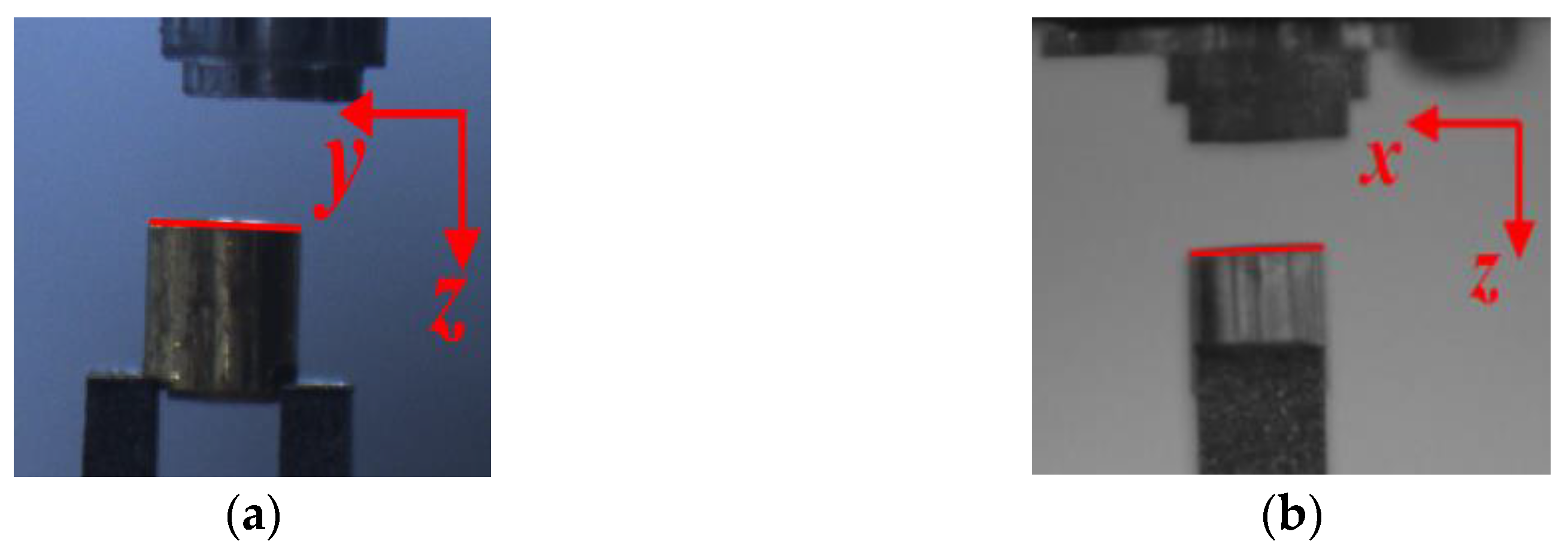
5.2.1. Posture Adjustment Based on Visual Guidance

The visual guidance process was divided into three main segments. The photos of the parts to be assembled were acquired in the first session. CCD camera 1 and CCD camera 2 were switched on first. To gather picture information of the left side and the front side of the hohlraum, the parameters of CCD cameras 1 and 2 were changed. The pictures captured by CCD camera 1 and CCD camera 2 are shown in Figure 15a,b, respectively. The TMP component was then progressively moved into the present camera field of view by modifying the six DoF micromotion stage.
Image calibration was done in the second session. The reference object was chosen first in the calibration process. The hohlraum in the CCD camera 1 picture and the hohlraum in the CCD camera 2 images were then calibrated by drawing lines to ascertain the correspondence between the images and the real component size, respectively. The diameter of the outer ring of the hohlraum was utilized as the reference size in this experiment, and the diameter of the outer ring of the hohlraum employed was 2700 μm. The size calibration for the CCD camera 1 picture and the CCD camera 2 images is shown in Figure 16a,b, respectively.
The positional adjustment of the two components was done in the third session. The current TMP component posture was first identified in the posture adjustment process by drawing lines for the TMP component in the CCD camera 1 and CCD camera 2 pictures, respectively. The part posture calibration for the CCD camera 1 picture and CCD camera 2 images is shown in Figure 17a,b. The posture deviations in the assembly system’s coordinate system are θx and θy, and the position deviations are ex, ey, and ez, respectively, based on the picture calibration results. According to the kinematic analysis of the six DoF micromotion stage, it is known that after the posture adjustment, the kinematic model position deviation fulfills
{ Δ x = h 1 sin θ x + ( d 6 + h 3 ) cos θ y cos θ x h 2 cos θ x sin θ y d 6 h 3 + e z Δ y = h 1 cos θ x ( d 6 + h 3 ) cos θ y sin θ x + h 2 sin θ y sin θ x + h 1 e y Δ z = h 2 cos θ y + ( d 6 + h 3 ) sin θ y + h 2 e x
The final adjustments to attitude and position were made. The finished final TMP component posture adjustment is shown in Figure 18a,b. The finished assembly of the component shaft hole is shown in Figure 19a,b.

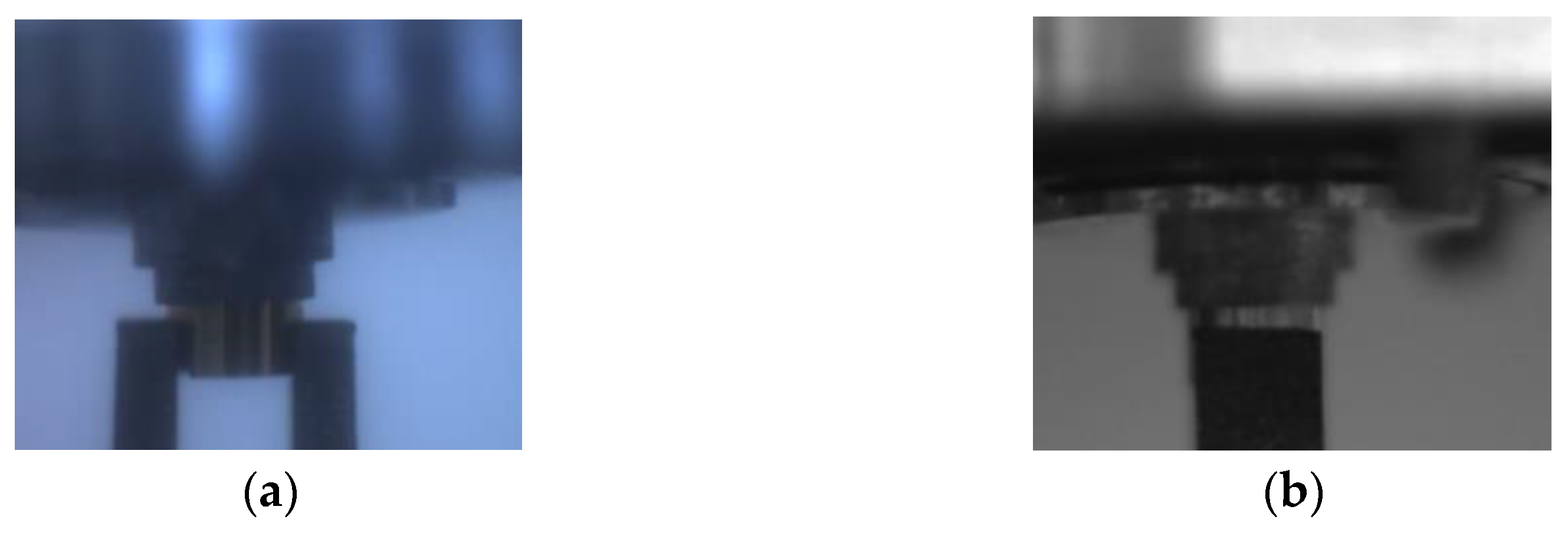
5.2.2. Force Guidance in TMP-Hohlraum Component

Following the completion of the visual guiding, the final shaft-hole contact assembly was finished using microforce control. The deflection of the radial direction of the part was regulated in the force control link by selecting the radial contact force threshold value. Figure 20a–c depicts the comparison of force states when different force feedback levels were established, respectively. Combining the radial force variations in Figure 20a,b, it can be seen that the overall change in radial force is relatively small and did not change too abruptly when a smaller force feedback threshold was set compared to a larger one. According to Figure 20c, the threshold value of radial contact force has a more negligible effect on the axial assembly force of the part.
The experiments show that the flexible control system combining microscopic visual inspection, multisource microforce sensing, and autonomous part position correction is superior for fragile parts such as hohlraums compared to single visual inspection and guided micropart assembly control. However, due to the rarity and fragility of the hohlraum, we were unable to conduct a large number of repeatable experiments to increase the credibility of our conclusions.

6. Conclusions

Based on the analysis of the adsorption force of the silicon arm adsorber, the six DoF pose calculation between the hohlraum and the TMP component was completed in this article. At the same time, we propose a flexible assembly control structure combining multisource microforce sensing and a six DoF attitude adjustment. On the basis of a flexible assembly control structure, a flexible assembly approach combining master and slave was presented, which can realize flexible control of the assembly force. Following the experimental demonstration, the approach can effectively adjust part posture based on posture deviation results and assembly force detection, allowing for the nondestructive assembly of TMP components and hohlraum. Moreover, the modified method applies to microdevice interference shaft hole assembly. It can effectively improve the success rate of thin-walled deep-cavity assembly relative to the microscopic visual alignment method. Compared to rigid assembly methods, our method significantly reduces sudden fluctuations in contact force during assembly to allow for a smoother transition of assembly force when parts come into contact. Relative to the active/passive supple control strategy, it can simplify the complexity of the system structure and positional decoupling and enhance the visibility of the operation.
The solution suggested in this research solves the problem of thin-walled deep-cavity class parts being vulnerable during interference bore assembly. The procedure, on the other hand, has only been tested in small quantities under limited experimental conditions, and the method’s success rate has not been determined through a significant number of assembly trials. The next step will be to conduct an experimental analysis to determine the method’s dependability and to optimize the control algorithm.

Author Contributions

Conceptualization, T.C., K.N., M.Z.; methodology, T.C., K.N.; software, K.N.; validation, K.N.; formal analysis, T.C., K.N.; investigation, T.C., M.Z.; resources, T.C.; data curation, K.N.; writing—original draft preparation, K.N.; writing—review and editing, K.N., M.Z.; visualization, K.N.; supervision, T.C., M.Z.; funding acquisition, T.C., L.S. All authors have read and agreed to the published version of the manuscript.

Funding

This work was supported by the National Key Research and Development Program of China (Grant numbers 2019YFB1310900).

Institutional Review Board Statement

Not applicable.

Informed Consent Statement

Not applicable.

Data Availability Statement

The data presented in this study are available on request from the corresponding author.

Conflicts of Interest

The authors declare no conflict of interest.

References

  1. Huang, X.H. Microassembly robot: Key technology, development, and applications. CAAI Trans. Intell. Syst. 2020, 15, 413–424. [Google Scholar]
  2. Yang, G.; Gaines, J.A.; Nelson, B.J. A Supervisory Wafer-Level 3D Microassembly System for Hybrid MEMS Fabrication. J. Intell. Robot. Syst. 2003, 37, 43–68. [Google Scholar] [CrossRef]
  3. Qiu, Z.; Wang, T.; Wang, J.; Li, X.; Zhong, Y. Online detection system of microtarget assembly. J. Vac. Sci. Technol. B Microelectron. Nanometer Struct. 2009, 27, 1890. [Google Scholar] [CrossRef]
  4. Yang, G.; Gaines, J.; Nelson, B. Optomechatronic Design of Microassembly Systems for Manufacturing Hybrid Microsystems. IEEE Trans. Ind. Electron. 2005, 52, 1013–1023. [Google Scholar] [CrossRef]
  5. Castro, C.; Montesanti, R.C.; Taylor, J.S.; Hamza, A.V.; Dzenitis, E.G. Reconfigurable Assembly Station for Precision Manufacture of Nuclear Fusion Ignition Targets. In Proceedings of the ASPE 24th Annual Meeting, Monterey, CA, USA, 4–9 October 2009. [Google Scholar]
  6. Carlson, L.C.; Huang, H.; Alexander, N.; Bousquet, J.; Farrell, M.; Nikroo, A. Automation of NIF Target Fabrication. Fusion Sci. Technol. 2016, 70, 274–287. [Google Scholar] [CrossRef]
  7. Wu, W.R.; Huang, L.Z.; Luo, M.; Yang, S.J.; Wang, H.L. Research on Semi-automatic Assembly Technology of Micro-target. In Proceedings of the 10th China Nuclear Target Technology Academic Exchange deep Conference, Lanzhou, China, 17 November 2009. [Google Scholar]
  8. Wang, S.; Chen, G.; Xu, H.; Wang, Z. A Robotic Peg-in-Hole Assembly Strategy Based on Variable Compliance Center. IEEE Access 2019, 7, 167534–167546. [Google Scholar] [CrossRef]
  9. Montesanti, R.C.; Alger, E.T.; Atherton, L.J.; Bhandarkar, S.; Castro, C.; Dzenitis, E.G.; Edwards, G.J.; Hamza, A.V.; Klingmann, J.L.; Lord, D.M.; et al. Lessons from Building Laser-Driven Fusion Ignition Targets with the Precision Robotic Assembly Machine. Fusion Sci. Technol. 2011, 59, 70–77. [Google Scholar] [CrossRef]
  10. Yu, D.H.; Wu, W.R.; Shen, F.; Liu, G.D.; Liu, B.G.; Chen, F.D.; Wan, F. Precision robotic system designed for hohlraum assembly. Laser Part. Beams 2014, 26, 164–169. [Google Scholar]
  11. Whitney, D.E. Historical-perspective and state-of-the-art in robot force control. Int. J. Robot Res. 1987, 6, 3–14. [Google Scholar] [CrossRef]
  12. Park, D.I.; Kim, H.; Park, C.; Choi, T.; Do, H.; Kim, B.; Park, J. Automatic assembly method with the passive compliant device. In Proceedings of the 11th Asian Control Conference (ASCC), Gold Coast, QLD, Australia, 17–20 December 2017; pp. 347–348. [Google Scholar] [CrossRef]
  13. Jakovljevic, Z.; Petrovic, P.B.; Mikovic, V.D.; Pajic, M. Fuzzy inference mechanism for recognition of contact states in intelligent robotic assembly. J. Intell. Manuf. 2012, 25, 571–587. [Google Scholar] [CrossRef]
  14. Wang, Y.Q.; Wu, M.Y.; Yang, Z.; Sun, L.N. Study of Cooperative system of Mico-nano-operated Robot based on SEM. In Proceedings of the 36th China Control Conference (CCC2017), Dalian, China, 26–28 July 2017; pp. 1541–1544. [Google Scholar]
Figure 1. (a) Three-dimensional structure diagram of sleeve, (b) 3D structure diagram of hohlraum, (c) 3D structure diagram of half-hohlraum component.
Actuators 12 00001 g001
Figure 2. Structure of the flexible assembly system.
Actuators 12 00001 g002
Figure 3. Sectional view of TMP component and hohlraum.
Actuators 12 00001 g003
Figure 4. Mechanical analysis diagram of flexible support platform.
Actuators 12 00001 g004
Figure 5. Diagrams of analysis of clamping forces and displacements. (a) Integral moment analysis; (b) Force analysis of the platform; (c) Force analysis of Gripper’s end.
Actuators 12 00001 g005
Figure 6. Kinematic parameters and coordinate settings of a six DoF micromotion stage.
Actuators 12 00001 g006
Figure 7. Posture adjustment status of TMP component and hohlraum. (a) Parts without attitude adjustment; (b) Parts with attitude adjustment; (c) Parts after contact.
Actuators 12 00001 g007
Figure 8. Flowchart of posture adjustment based on visual guidance.
Actuators 12 00001 g008
Figure 9. Schematic of the force adjustment trajectory of TMP component and hohlraum. (a) Force of contact in horizontal and vertical directions are lower than the safe threshold; (b) Contact force in horizontal direction is higher than safety threshold; (c) Contact force in vertical direction is lower than safe threshold.
Actuators 12 00001 g009
Figure 10. Flowchart of adjustment based on assembly force.
Actuators 12 00001 g010
Figure 11. Rigid assembly platform of TMP component and hohlraum.
Actuators 12 00001 g011
Figure 12. Force state diagram of flexible support platform and rigid support platform in assembly. (a) Comparison of radial force of flexible support platform and rigid platform for the first assembly experiment; (b) Comparison of radial force of flexible support platform and rigid platform for the second assembly experiment; (c) Comparison of axial force of flexible support platform and rigid platform in assembly experiment.
Actuators 12 00001 g012
Figure 13. Diagram of hohlraum’s offset.
Actuators 12 00001 g013
Figure 14. Flexible assembly platform of TMP component and hohlraum.
Actuators 12 00001 g014
Figure 15. Images of TMP component and hohlraum acquired through the CCD. (a) Front view of the hohlraum when unassembled; (b) Image of the left side of the hohlraum when unassembled; (c) Front view of the sleeve after it enters the assembly area; (d) Image of the left side of the sleeve after it enters the assembly area.
Actuators 12 00001 g015
Figure 16. Size calibration of CCD. (a) Draw lines on the hohlraum to mark its front size; (b) Draw a line on the hohlraum to mark its left side size.
Actuators 12 00001 g016
Figure 17. Size calibration of CCD. (a) Draw lines on the sleeve to mark its frontal posture; (b) Draw lines to sleeve to mark its left posture.
Actuators 12 00001 g017
Figure 18. Parts pose calibration of CCD. (a) Front view of sleeve after posture adjustment; (b) Left side view of sleeve after posture adjustment.
Actuators 12 00001 g018
Figure 19. Parts pose calibration of CCD 2. (a) Front view of the TMP—Component after assembly; (b) Left view of the TMP-Component after assembly.
Actuators 12 00001 g019
Figure 20. Comparison chart of the forced states with different force feedback thresholds. (a) Comparison of radial forces at different force feedback thresholds in the first assembly experiment; (b) Comparison of radial forces at different force feedback thresholds in the second assembly experiment; (c) Comparison of axial force at different force feedback thresholds.
Actuators 12 00001 g020
Table 1. Parameters of Nano17.
ParametersIndex
RangeFx, Fy: ±12 N; Fz: ±17 N; Tx, Ty, Tz: ±120 N·mm
Overload protection3.1 to 13.8 times F.S.
Unidirectional linearity<0.05%F.S.
Coupling error<0.5%F.S.
Response frequency7200 Hz
Table 2. Parameters of cantilever beam sensor.
ParametersIndex
Sensitivity2.0 ± 0.05 mV
Overload protection≤150%F.S.
Nonlinear≤±0.03%F.S.
Operating temperature−20~80 °C
Excitation voltage10–15 V
Table 3. Main parameters of the 6 DoF micromotion platform.
ModelItineraryOne—Way Positioning PrecisionRepeatability Accuracy
KXL0605050 mm5 μm±0.3 μm
KXL0607575 mm5 μm±0.3 μm
KRW04360360°0.05°±0.01°
KRW06360360°0.05°±0.01°
KGW04040±8°±0.005°
Table 4. Parameters related to each joint of the six DoF micromotion stage.
iαi−1ai−1diθi
100d1 (0–70 mm)0
2−90°a1 (42 mm)d2 (0–50 mm)90°
390°a2 (46 mm)d3 (0–70 mm)−90°
4−90°0d4θ4 (−90° ± 180°)
5−90°00θ5 (−90° ± 120°)
690°0d6θ6 (−90° ± 180°)
Disclaimer/Publisher’s Note: The statements, opinions and data contained in all publications are solely those of the individual author(s) and contributor(s) and not of MDPI and/or the editor(s). MDPI and/or the editor(s) disclaim responsibility for any injury to people or property resulting from any ideas, methods, instructions or products referred to in the content.

